

Page 1
English
YHT-394 Home Theater Package
Connection Guide
G
Printed in China WV59530
© 2010 Yamaha Corporation
The Yamaha YHT-394 Home Theater Package includes everything you need to add great sound
Part A: Speakers and Antennas
1
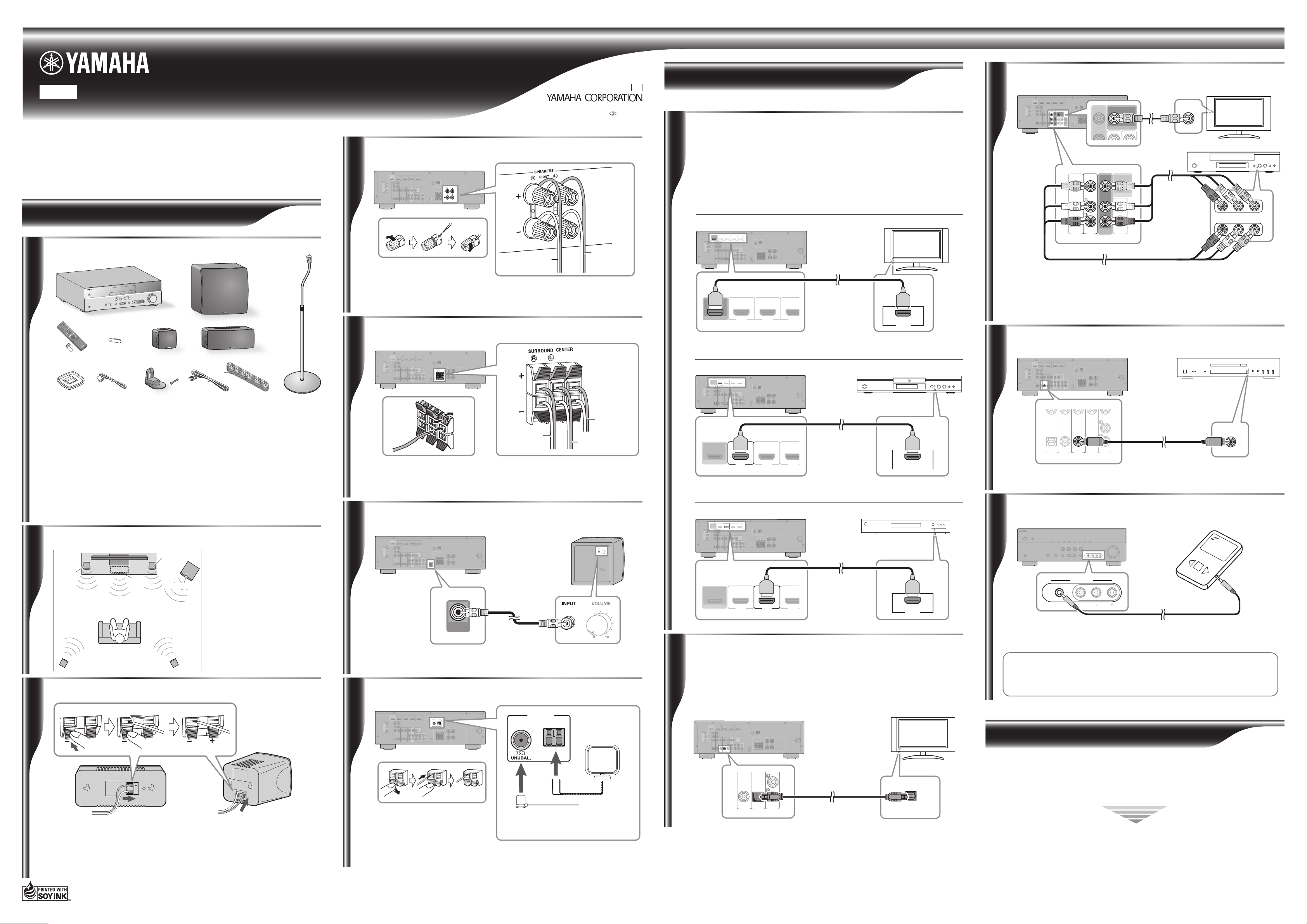
Unpack and check the package contents. The following items are necessary to complete this
Connection Guide.
A AV Receiver (HTR-3063)
B Remote control and two batteries
(AAA, R03, UM-4)
C Front input jacks cover
D AM antenna
E FM antenna
F Subwoofer (NS-SW280)
G Front/surround speaker (NS-B285)
H Center speaker (NS-C385)
I Speaker stand and screw for NS-B285
J Subwoofer cable
K Speaker cable
L Speaker stand (SPS-90)
(Assembled stand shown)
In the NS-P285 (Speaker Package) Owner’s Manual included with the YHT-394, it states
that four mini speaker stands are included. However, two of these have been replaced with
SPS-90 speaker stands. Refer to the relevant owner’s manuals for the correct product
operating instructions.
Checking the package contents
x 2
x 4
x 2
2
The four front and surround
speakers are identical, so it
doesn’t matter which one you use
in each position.
Position the speakers as shown.
See the owner’s manuals for more
information on installing the
speakers.
Positioning the speakers
Front
left
Front
right
Subwoofer
Surround
left
Surround
right
Center
3
• Cut the included speaker cable to suitable lengths for the front, center, and surround
speakers. You need to make five cables altogether. Remove about 10 mm (3/8 in.) of
insulation from the end of each cable, and then twist the bare strands tightly.
• Connect the speaker cables to the front speakers (G), surround speakers (G), and center
speaker (H). Make sure you connect the speakers with the correct polarity—positive (+)
terminals to positive (+) terminals, and negative (–) terminals to negative (–) terminals.
Front, Surround
speakers
Preparing the cables and speakers
Center speaker
4
AV Receiver
Connect the front speaker (G) cables to the AV Receiver. Make sure you connect the
speakers with the correct polarity—positive (+) terminals to positive (+) terminals, and
negative (–) terminals to negative (–) terminals.
To front left
speaker
To front right
speaker
Connecting the front speakers
Connecting the center and surround speakers
5
AV Receiver
Connect the center speaker (H) and surround speaker (G) cables to the AV Receiver.
Make sure you connect the speakers with the correct polarity—positive (+) terminals
to positive (+) terminals, and negative (–) terminals to negative (–) terminals.
To surround
right speaker
To center
speaker
To surround
left speaker
AV Receiver
6
Subwoofer
Use the included subwoofer cable (J) to connect the Subwoofer’s INPUT jack to the
AV Receiver’s SUBWOOFER jack.
Connecting the subwoofer
Subwoofer
cable
Connecting the antennas
ANTENNA
FM
GND
AM
COMPONENT
VIDEO
P
R
P
B
Y
OPTICAL
(
TV
)
AV 1
AV 2
AV 3
AV 4
AV 5
AUDIO 1
AUDIO 2
COAXIAL
(CD)
COAXIAL
OPTICAL
VIDEO
CENTER
SURROUND
HDMI 1
(
BD/DVD
)
HDMI 2 HDMI 3
HDMI 4
FRONT
COMPONENT
VIDEO
MONITOR OUT
P
R
P
B
Y
HDMI
OUT
MONITOR OUT
AV
OUT
SUBWOOFER
AUDIO
OUT
SPEAKERS
ANTENNA
FM
GND
AM
7
AV Receiver
Connect the AM loop antenna (D) and indoor FM antenna (E) to the AV Receiver,
as shown. See the owner’s manuals for more information about connecting antennas.
AM antenna
FM antenna
(FM antenna type depends
on destination country.)
Part B: AV Components
Connecting HDMI-capable components
ANTENNA
FM
GND
AM
COMPONENT
VIDEO
P
R
P
B
Y
OPTICAL
(
TV
)
AV 1
AV 2
AV 3
AV 4
AV 5
AUDIO 1
AUDIO 2
COAXIAL
(CD)
COAXIAL
OPTICAL
VIDEO
CENTER
SURROUND
HDMI 1
(
BD/DVD
)
HDMI 2 HDMI 3
HDMI 4
FRONT
COMPONENT
VIDEO
MONITOR OUT
P
R
P
B
Y
HDMI
OUT
MONITOR OUT
AV
OUT
SUBWOOFER
AUDIO
OUT
SPEAKERS
HDMI
IN
1
AV Receiver TV
If your TV and DVD player or satellite/cable set-top box have HDMI jacks, you can
connect them via the AV Receiver. Using HDMI cables (not included), connect the AV
Receiver’s HDMI OUT jack to an HDMI input on your TV, and connect your DVD
player and satellite/cable set-top box to the AV Receiver’s HDMI 1(BD/DVD) and
HDMI 2 jacks, respectively, as shown.
See the owner’s manuals for more information about HDMI.
● Connecting your TV
● Connecting your DVD player
AV Receiver DVD player
● Connecting your satellite/cable set-top box
ANTENNA
FM
GND
AM
COMPONENT
VIDEO
P
R
P
B
Y
OPTICAL
(
TV
)
AV 1
AV 2
AV 3
AV 4
AV 5
AUDIO 1
AUDIO 2
COAXIAL
(CD)
COAXIAL
OPTICAL
VIDEO
CENTER
SURROUND
FRONT
COMPONENT
VIDEO
MONITOR OUT
P
R
P
B
Y
MONITOR OUT
AV
OUT
SUBWOOFER
AUDIO
OUT
SPEAKERS
HDMI
OUT
HDMI 1
(
BD/DVD
)
HDMI 3
HDMI 4
HDMI 2
HDMI
OUT
AV Receiver Satellite/cable set-top box
2
AV Receiver
TV
You can listen to TV audio through the AV Receiver and speakers by connecting an
audio output on your TV to an audio input on the AV Receiver with, for example, an
optical digital audio cable (not included), as shown.
To listen to TV audio, select the appropriate input source on the AV Receiver.
Connecting your TV for audio output
Connecting your DVR/VCR
R
L
(
TV
)
AV 4
AV 5
AUDIO 1
OPTICAL
MONITOR O
AV
OUT
3
AV Receiver
TV
Use a video pin cable (not included) to connect the AV Receiver’s MONITOR OUT
jack to a composite video input on your TV, as shown.
DVR/VCR
Use AV pin cables (not included) to connect your DVR (digital video recorder) or
VCR to the AV Receiver’s AV 5 and AV OUT jacks, as shown.
Connecting your DVR/VCR
Connecting your CD player
(
TV
)
AV 4
OPTICAL
COMPONENT
VIDEO
Y
OPTICAL
AV 1
AV 2
AV 3
AV 5
COAXIAL
(CD)
COAXIAL
VIDEO
4
AV Receiver CD player
Use an audio pin cable (not included) to connect your CD player to the AV Receiver’s
AV 3 COAXIAL(CD) jacks, as shown.
Connecting your portable music player
5
AV Receiver Portable music player
Use a 3.5 mm stereo mini plug cable (not included) to connect your portable music player
to the AV Receiver’s PORTABLE jack (on the front panel), as shown.
If your AV Receiver has a DOCK jack (U.S.A. and Canada models), you can
connect a Yamaha Universal Dock for iPod, such as the YDS-12, or a Yamaha
Bluetooth Wireless Audio Receiver, such as the YBA-10 (both sold separately).
See the AV Receiver’s Owner’s Manual for more information.
Almost Finished
to your home theater. By following the steps in this Connection Guide, you’ll have your home
theater set up in no time and be enjoying music and movies like never before. Part A explains how
to connect the speakers and antennas. Part B explains how to connect various AV components.
See the relevant owner’s manuals for full instructions and precautions.
Caution: Disconnect all components from AC outlets before proceeding.
Caution: Disconnect all components from AC outlets before proceeding.
(
)
BD/DVD
OUT
HDMI
HDMI 2 HDMI 3
HDMI 1
COMPONENT
VIDEO
P
R
P
R
P
B
P
B
Y
Y
MONITOR OUT
COMPONENT
VIDEO
VIDEO
COAXIAL
COAXIAL
OPTICAL
OPTICAL
(CD)
(
)
TV
AV 3
AV 4
AV 5
AV 2
AV 1
ANTENNA
HDMI 4
FM
GND
AM
SPEAKERS
FRONT
CENTER
SURROUND
MONITOR OUT
AV
AUDIO
SUBWOOFER
OUT
OUT
AUDIO 1
AUDIO 2
(
)
BD/DVD
OUT
HDMI
HDMI 2 HDMI 3
HDMI 1
COMPONENT
VIDEO
P
R
P
R
P
B
P
B
Y
Y
MONITOR OUT
COMPONENT
VIDEO
VIDEO
COAXIAL
COAXIAL
OPTICAL
OPTICAL
(CD)
(
)
TV
AV 3
AV 4
AV 5
AV 2
AV 1
ANTENNA
HDMI 4
FM
GND
AM
SPEAKERS
FRONT
CENTER
SURROUND
MONITOR OUT
AV
AUDIO
SUBWOOFER
OUT
OUT
AUDIO 1
AUDIO 2
MONITOR OUT
VIDEO
IN
R
L
AUDIO
VIDEO
OUT
A
MEMORY
INFO
INPUT
PHONES
CINEMA
SILENT
AMP
TRANSMIT
SLEEP
HDMI
AV
AUDIO
1 25
1234
123 4
TUNING
V-AUX
PRESET
SUR.DECODE
AM
TUNER
BC
ENHANCER
FM
MEMORY
STEREO
STRAIGHT
INFO
RADIO
MUSIC
CD
SCENE
MOVIE
OPTION
TV
VOLUME
BD
DVD
SETUP
MUTE
ENTER
RETURN
DE
TUNING
FMAM
PRESET
SCENE
CD
TV
BD
DVD
PROGRAM
CONTROL
TONE
VOLUME
RADIO
AUX
VIDEO
STRAIGHT
AUDIO
L R
VIDEO
PORTABLE
GH
IJ K
F
L
HDMI
(
)
BD/DVD
OUT
HDMI
HDMI 2 HDMI 3
HDMI 1
COMPONENT
VIDEO
P
R
P
R
P
B
P
B
Y
Y
MONITOR OUT
COMPONENT
VIDEO
VIDEO
COAXIAL
COAXIAL
OPTICAL
OPTICAL
AV
(CD)
(
)
TV
OUT
AV 3
AV 4
AV 5
AV 2
AV 1
ANTENNA
HDMI 4
FM
GND
AM
SPEAKERS
FRONT
CENTER
SURROUND
MONITOR OUT
AUDIO
SUBWOOFER
OUT
AUDIO 1
AUDIO 2
OUT
HDMI
COMPONENT
VIDEO
P
R
P
R
P
B
P
B
Y
Y
MONITOR OUT
COMPONENT
HDMI 1
(
)
BD/DVD
HDMI 4
HDMI 2 HDMI 3
HDMI 1
MONITOR OUT
VIDEO
VIDEO
COAXIAL
COAXIAL
OPTICAL
OPTICAL
AV
(CD)
(
)
TV
OUT
AV 3
AUDIO 1
AV 4
AV 5
AV 2
AV 1
AUDIO 2
AUDIO
SUBWOOFER
OUT
HDMI 2 HDMI 3
ANTENNA
FM
GND
AM
SPEAKERS
FRONT
CENTER
SURROUND
SURROUND
(
)
BD/DVD
OUT
HDMI
HDMI 2 HDMI 3
HDMI 1
COMPONENT
VIDEO
P
R
P
R
P
B
P
B
Y
Y
MONITOR OUT
COMPONENT
VIDEO
VIDEO
COAXIAL
COAXIAL
OPTICAL
OPTICAL
(CD)
(
)
TV
AV 3
AV 4
AV 5
AV 2
AV 1
ANTENNA
HDMI 4
FM
GND
AM
SPEAKERS
FRONT
CENTER
SURROUND
MONITOR OUT
AV
AUDIO
SUBWOOFER
OUT
OUT
AUDIO 1
AUDIO 2
(
)
BD/DVD
OUT
1
3
2
(
)
BD/DVD
OUT
HDMI
HDMI 1
HDMI 2 HDMI 3
OUT
HDMI
COAXIAL
(
)
BD/DVD
OUT
HDMI
HDMI 2 HDMI 3
HDMI 1
COMPONENT
VIDEO
P
R
P
R
P
B
P
B
Y
Y
MONITOR OUT
COMPONENT
VIDEO
VIDEO
COAXIAL
COAXIAL
OPTICAL
OPTICAL
AV
(CD)
(
)
TV
OUT
AV 3
AV 4
AV 5
AV 2
AV 1
ANTENNA
HDMI 4
FM
GND
AM
SPEAKERS
FRONT
CENTER
SURROUND
MONITOR OUT
AUDIO
SUBWOOFER
OUT
AUDIO 1
AUDIO 2
(
)
BD/DVD
OUT
HDMI
HDMI 1
HDMI 2
HDMI 3
INPUT
PORTABLE
SCENE
CONTROL
PROGRAM
STRAIGHT
PORTABLE
AUX
VIDEO
VIDEO
VOLUME
AUX
VIDEO
VIDEO
AUDIO
AUDIO
SUBWOOFER
(
)
BD/DVD
OUT
HDMI
HDMI 2 HDMI 3
HDMI 1
COMPONENT
VIDEO
P
R
P
R
P
B
P
B
Y
Y
MONITOR OUT
COMPONENT
VIDEO
VIDEO
COAXIAL
COAXIAL
OPTICAL
OPTICAL
(CD)
(
)
TV
AV 3
AV 4
AV 5
AV 2
AV 1
ANTENNA
HDMI 4
FM
GND
AM
SPEAKERS
FRONT
CENTER
SURROUND
MONITOR OUT
AV
AUDIO
SUBWOOFER
OUT
OUT
AUDIO 1
AUDIO 2
• Connect the AV Receiver, Subwoofer, and your other AV components to suitable AC outlets.
• Turn on the AV Receiver first, then the Subwoofer and your other AV components.
• Install the batteries in the AV Receiver’s remote control.
OPTICAL
• The optimum crossover frequency setting on the AV receiver is 150–160 Hz.
• See the relevant owner’s manuals for full operating instructions.
COAXIAL
OPTICAL
(CD)
(
)
TV
AV 4AV 3 AV 5
AUDIO OUTPUT
Time to enjoy your Yamaha Home Theater Package!
Now, relax and enjoy the great sound of your Yamaha Home Theater Package.
 Loading...