

Page 1

AV Receiver
Owner’s Manual
English
Read the supplied booklet “Safety Brochure” before using the unit.
Page 2

CONTENTS
Accessories . . . . . . . . . . . . . . . . . . . . . . . . . . . . . . . . . . . . . . . . . . . . . . . . . . . . . . 4
FEATURES 5
What you can do with the unit . . . . . . . . . . . . . . . . . . . . . . . . . . . . . . . . . . . . 5
Part names and functions . . . . . . . . . . . . . . . . . . . . . . . . . . . . . . . . . . . . . . . . 7
Front panel . . . . . . . . . . . . . . . . . . . . . . . . . . . . . . . . . . . . . . . . . . . . . . . . . . . . . . . . . . . . . . . . . . . . . . . . . . . . . . . . . . . . . . . . 7
Front display (indicators) . . . . . . . . . . . . . . . . . . . . . . . . . . . . . . . . . . . . . . . . . . . . . . . . . . . . . . . . . . . . . . . . . . . . . . . . . . . 8
Rear panel . . . . . . . . . . . . . . . . . . . . . . . . . . . . . . . . . . . . . . . . . . . . . . . . . . . . . . . . . . . . . . . . . . . . . . . . . . . . . . . . . . . . . . . . . 9
Remote control . . . . . . . . . . . . . . . . . . . . . . . . . . . . . . . . . . . . . . . . . . . . . . . . . . . . . . . . . . . . . . . . . . . . . . . . . . . . . . . . . . . 10
PREPARATIONS 11
General setup procedure . . . . . . . . . . . . . . . . . . . . . . . . . . . . . . . . . . . . . . . . 11
1 Placing speakers . . . . . . . . . . . . . . . . . . . . . . . . . . . . . . . . . . . . . . . . . . . . . . 12
2 Connecting speakers . . . . . . . . . . . . . . . . . . . . . . . . . . . . . . . . . . . . . . . . . . 15
Input/output jacks and cables . . . . . . . . . . . . . . . . . . . . . . . . . . . . . . . . . . . 17
3 Connecting a TV . . . . . . . . . . . . . . . . . . . . . . . . . . . . . . . . . . . . . . . . . . . . . . . 18
4 Connecting playback devices . . . . . . . . . . . . . . . . . . . . . . . . . . . . . . . . . . 20
Connecting video devices (such as BD/DVD players) . . . . . . . . . . . . . . . . . . . . . . . . . . . . . . . . . . . . . . . . . . . . . . . 20
Connecting audio devices (such as CD players) . . . . . . . . . . . . . . . . . . . . . . . . . . . . . . . . . . . . . . . . . . . . . . . . . . . . . 22
Connecting to the jack on the front panel . . . . . . . . . . . . . . . . . . . . . . . . . . . . . . . . . . . . . . . . . . . . . . . . . . . . . . . . . . 23
5 Connecting the FM/AM antennas . . . . . . . . . . . . . . . . . . . . . . . . . . . . . . . 23
6 Connecting recording devices . . . . . . . . . . . . . . . . . . . . . . . . . . . . . . . . . . 24
7 Connecting the power cable . . . . . . . . . . . . . . . . . . . . . . . . . . . . . . . . . . . 24
8 Selecting an on-screen menu language . . . . . . . . . . . . . . . . . . . . . . . . . 25
9 Optimizing the speaker settings automatically (YPAO) . . . . . . . . . . 26
Error messages . . . . . . . . . . . . . . . . . . . . . . . . . . . . . . . . . . . . . . . . . . . . . . . . . . . . . . . . . . . . . . . . . . . . . . . . . . . . . . . . . . . . 28
Warning messages . . . . . . . . . . . . . . . . . . . . . . . . . . . . . . . . . . . . . . . . . . . . . . . . . . . . . . . . . . . . . . . . . . . . . . . . . . . . . . . .29
PLAYBACK 30
Basic playback procedure . . . . . . . . . . . . . . . . . . . . . . . . . . . . . . . . . . . . . . . 30
Switching information on the front display . . . . . . . . . . . . . . . . . . . . . . . . . . . . . . . . . . . . . . . . . . . . . . . . . . . . . . . . .30
Selecting the input source and favorite settings with one touch
(SCENE) . . . . . . . . . . . . . . . . . . . . . . . . . . . . . . . . . . . . . . . . . . . . . . . . . . . . . . . . 31
Configuring scene assignments . . . . . . . . . . . . . . . . . . . . . . . . . . . . . . . . . . . . . . . . . . . . . . . . . . . . . . . . . . . . . . . . . . . .31
Selecting the sound mode . . . . . . . . . . . . . . . . . . . . . . . . . . . . . . . . . . . . . . . 32
Enjoying sound field effects (CINEMA DSP) . . . . . . . . . . . . . . . . . . . . . . . . . . . . . . . . . . . . . . . . . . . . . . . . . . . . . . . . .33
Enjoying unprocessed playback . . . . . . . . . . . . . . . . . . . . . . . . . . . . . . . . . . . . . . . . . . . . . . . . . . . . . . . . . . . . . . . . . . . 35
Enhancing the bass (Extra Bass) . . . . . . . . . . . . . . . . . . . . . . . . . . . . . . . . . . . . . . . . . . . . . . . . . . . . . . . . . . . . . . . . . . . .36
Enjoying compressed music with enhanced sound (Compressed Music Enhancer) . . . . . . . . . . . . . . . . . . .36
Listening to FM/AM radio . . . . . . . . . . . . . . . . . . . . . . . . . . . . . . . . . . . . . . . 37
Setting the frequency steps . . . . . . . . . . . . . . . . . . . . . . . . . . . . . . . . . . . . . . . . . . . . . . . . . . . . . . . . . . . . . . . . . . . . . . . .37
Selecting a frequency for reception . . . . . . . . . . . . . . . . . . . . . . . . . . . . . . . . . . . . . . . . . . . . . . . . . . . . . . . . . . . . . . . .37
Registering favorite radio stations (presets) . . . . . . . . . . . . . . . . . . . . . . . . . . . . . . . . . . . . . . . . . . . . . . . . . . . . . . . . 38
Radio Data System tuning . . . . . . . . . . . . . . . . . . . . . . . . . . . . . . . . . . . . . . . . . . . . . . . . . . . . . . . . . . . . . . . . . . . . . . . . .40
Playing back iPod music . . . . . . . . . . . . . . . . . . . . . . . . . . . . . . . . . . . . . . . . . 41
Connecting an iPod . . . . . . . . . . . . . . . . . . . . . . . . . . . . . . . . . . . . . . . . . . . . . . . . . . . . . . . . . . . . . . . . . . . . . . . . . . . . . . .41
Playback of iPod content . . . . . . . . . . . . . . . . . . . . . . . . . . . . . . . . . . . . . . . . . . . . . . . . . . . . . . . . . . . . . . . . . . . . . . . . . . 41
Playing back music stored on a USB storage device . . . . . . . . . . . . . . . 45
Connecting a USB storage device . . . . . . . . . . . . . . . . . . . . . . . . . . . . . . . . . . . . . . . . . . . . . . . . . . . . . . . . . . . . . . . . . .45
Playback of USB storage device contents . . . . . . . . . . . . . . . . . . . . . . . . . . . . . . . . . . . . . . . . . . . . . . . . . . . . . . . . . . .45
Configuring playback settings for different playback sources
(Option menu) . . . . . . . . . . . . . . . . . . . . . . . . . . . . . . . . . . . . . . . . . . . . . . . . . . 48
Option menu items . . . . . . . . . . . . . . . . . . . . . . . . . . . . . . . . . . . . . . . . . . . . . . . . . . . . . . . . . . . . . . . . . . . . . . . . . . . . . . . .48
En 2
Page 3

CONFIGURATIONS 51
Yamaha technologies . . . . . . . . . . . . . . . . . . . . . . . . . . . . . . . . . . . . . . . . . . . . . . . . . . . . . . . . . . . . . . . . . . . . . . . . . . . . .74
Supported devices and file formats . . . . . . . . . . . . . . . . . . . . . . . . . . . . . . 75
Configuring various functions (Setup menu) . . . . . . . . . . . . . . . . . . . . . . 51
Setup menu items . . . . . . . . . . . . . . . . . . . . . . . . . . . . . . . . . . . . . . . . . . . . . . . . . . . . . . . . . . . . . . . . . . . . . . . . . . . . . . . . 52
Speaker . . . . . . . . . . . . . . . . . . . . . . . . . . . . . . . . . . . . . . . . . . . . . . . . . . . . . . . . . . . . . . . . . . . . . . . . . . . . . . . . . . . . . . . . . . . 54
HDMI . . . . . . . . . . . . . . . . . . . . . . . . . . . . . . . . . . . . . . . . . . . . . . . . . . . . . . . . . . . . . . . . . . . . . . . . . . . . . . . . . . . . . . . . . . . . . 57
Sound . . . . . . . . . . . . . . . . . . . . . . . . . . . . . . . . . . . . . . . . . . . . . . . . . . . . . . . . . . . . . . . . . . . . . . . . . . . . . . . . . . . . . . . . . . . . 59
ECO . . . . . . . . . . . . . . . . . . . . . . . . . . . . . . . . . . . . . . . . . . . . . . . . . . . . . . . . . . . . . . . . . . . . . . . . . . . . . . . . . . . . . . . . . . . . . . 61
Function . . . . . . . . . . . . . . . . . . . . . . . . . . . . . . . . . . . . . . . . . . . . . . . . . . . . . . . . . . . . . . . . . . . . . . . . . . . . . . . . . . . . . . . . . . 62
Language . . . . . . . . . . . . . . . . . . . . . . . . . . . . . . . . . . . . . . . . . . . . . . . . . . . . . . . . . . . . . . . . . . . . . . . . . . . . . . . . . . . . . . . . . 63
Configuring the system settings (ADVANCED SETUP menu) . . . . . . . . 64
ADVANCED SETUP menu items . . . . . . . . . . . . . . . . . . . . . . . . . . . . . . . . . . . . . . . . . . . . . . . . . . . . . . . . . . . . . . . . . . . . 64
Changing the speaker impedance setting (SP IMP.) . . . . . . . . . . . . . . . . . . . . . . . . . . . . . . . . . . . . . . . . . . . . . . . . . 64
Selecting the remote control ID (REMOTE ID) . . . . . . . . . . . . . . . . . . . . . . . . . . . . . . . . . . . . . . . . . . . . . . . . . . . . . . . 65
Changing the FM/AM tuning frequency setting (TU) . . . . . . . . . . . . . . . . . . . . . . . . . . . . . . . . . . . . . . . . . . . . . . . . 65
Switching the video signal type (TV FORMAT) . . . . . . . . . . . . . . . . . . . . . . . . . . . . . . . . . . . . . . . . . . . . . . . . . . . . . . 65
Restoring the default settings (INIT) . . . . . . . . . . . . . . . . . . . . . . . . . . . . . . . . . . . . . . . . . . . . . . . . . . . . . . . . . . . . . . . . 65
Updating the firmware (UPDATE) . . . . . . . . . . . . . . . . . . . . . . . . . . . . . . . . . . . . . . . . . . . . . . . . . . . . . . . . . . . . . . . . . . 66
Checking the firmware version (VERSION) . . . . . . . . . . . . . . . . . . . . . . . . . . . . . . . . . . . . . . . . . . . . . . . . . . . . . . . . . . 66
APPENDIX 67
Frequently asked questions . . . . . . . . . . . . . . . . . . . . . . . . . . . . . . . . . . . . . 67
Troubleshooting . . . . . . . . . . . . . . . . . . . . . . . . . . . . . . . . . . . . . . . . . . . . . . . . 68
Power, system and remote control . . . . . . . . . . . . . . . . . . . . . . . . . . . . . . . . . . . . . . . . . . . . . . . . . . . . . . . . . . . . . . . . . 68
Audio . . . . . . . . . . . . . . . . . . . . . . . . . . . . . . . . . . . . . . . . . . . . . . . . . . . . . . . . . . . . . . . . . . . . . . . . . . . . . . . . . . . . . . . . . . . . . 69
Video . . . . . . . . . . . . . . . . . . . . . . . . . . . . . . . . . . . . . . . . . . . . . . . . . . . . . . . . . . . . . . . . . . . . . . . . . . . . . . . . . . . . . . . . . . . . . 70
FM/AM radio . . . . . . . . . . . . . . . . . . . . . . . . . . . . . . . . . . . . . . . . . . . . . . . . . . . . . . . . . . . . . . . . . . . . . . . . . . . . . . . . . . . . . . 71
USB . . . . . . . . . . . . . . . . . . . . . . . . . . . . . . . . . . . . . . . . . . . . . . . . . . . . . . . . . . . . . . . . . . . . . . . . . . . . . . . . . . . . . . . . . . . . . . . 71
Error indications on the front display . . . . . . . . . . . . . . . . . . . . . . . . . . . . . 72
Video signal flow . . . . . . . . . . . . . . . . . . . . . . . . . . . . . . . . . . . . . . . . . . . . . . . 75
Information on HDMI . . . . . . . . . . . . . . . . . . . . . . . . . . . . . . . . . . . . . . . . . . . 76
HDMI Control . . . . . . . . . . . . . . . . . . . . . . . . . . . . . . . . . . . . . . . . . . . . . . . . . . . . . . . . . . . . . . . . . . . . . . . . . . . . . . . . . . . . .76
Audio Return Channel (ARC) . . . . . . . . . . . . . . . . . . . . . . . . . . . . . . . . . . . . . . . . . . . . . . . . . . . . . . . . . . . . . . . . . . . . . . .77
HDMI signal compatibility . . . . . . . . . . . . . . . . . . . . . . . . . . . . . . . . . . . . . . . . . . . . . . . . . . . . . . . . . . . . . . . . . . . . . . . . .78
Reference diagram (rear panel) . . . . . . . . . . . . . . . . . . . . . . . . . . . . . . . . . . 79
Trademarks . . . . . . . . . . . . . . . . . . . . . . . . . . . . . . . . . . . . . . . . . . . . . . . . . . . . 80
Specifications . . . . . . . . . . . . . . . . . . . . . . . . . . . . . . . . . . . . . . . . . . . . . . . . . . 81
Index . . . . . . . . . . . . . . . . . . . . . . . . . . . . . . . . . . . . . . . . . . . . . . . . . . . . . . . . . . 83
Glossary . . . . . . . . . . . . . . . . . . . . . . . . . . . . . . . . . . . . . . . . . . . . . . . . . . . . . . . . 73
Audio information . . . . . . . . . . . . . . . . . . . . . . . . . . . . . . . . . . . . . . . . . . . . . . . . . . . . . . . . . . . . . . . . . . . . . . . . . . . . . . . . 73
HDMI and video information . . . . . . . . . . . . . . . . . . . . . . . . . . . . . . . . . . . . . . . . . . . . . . . . . . . . . . . . . . . . . . . . . . . . . . 74
En 3
Page 4

Accessories
30° 30°
Within 6 m (20 ft)
Check that the following accessories are supplied with the product.
Remote control Batteries (AAA, R03, UM-4) (x2)
Insert the batteries the right
way round.
AM antenna FM antenna
*One of the above is supplied depending on the region of
purchase.
Operating range of the remote control
• Point the remote control at the remote control sensor on the unit and remain within the operating range
shown below.
YPAO microphone CD-ROM (Owner’s Manual)
Easy Setup Guide
Safety Brochure
• Some features are not available in certain regions.
• Due to product improvements, specifications and appearance are subject to change without notice.
• This manual explains operations using the supplied remote control.
• This manual describes both the “iPod” and “iPhone” as the “iPod”. “iPod” refers to both “iPod” and
“iPhone”, unless otherwise specified.
• indicates precautions for use of the unit and its feature limitations.
• indicates supplementary explanations for better use.
Accessories En 4
Page 5
FEATURES
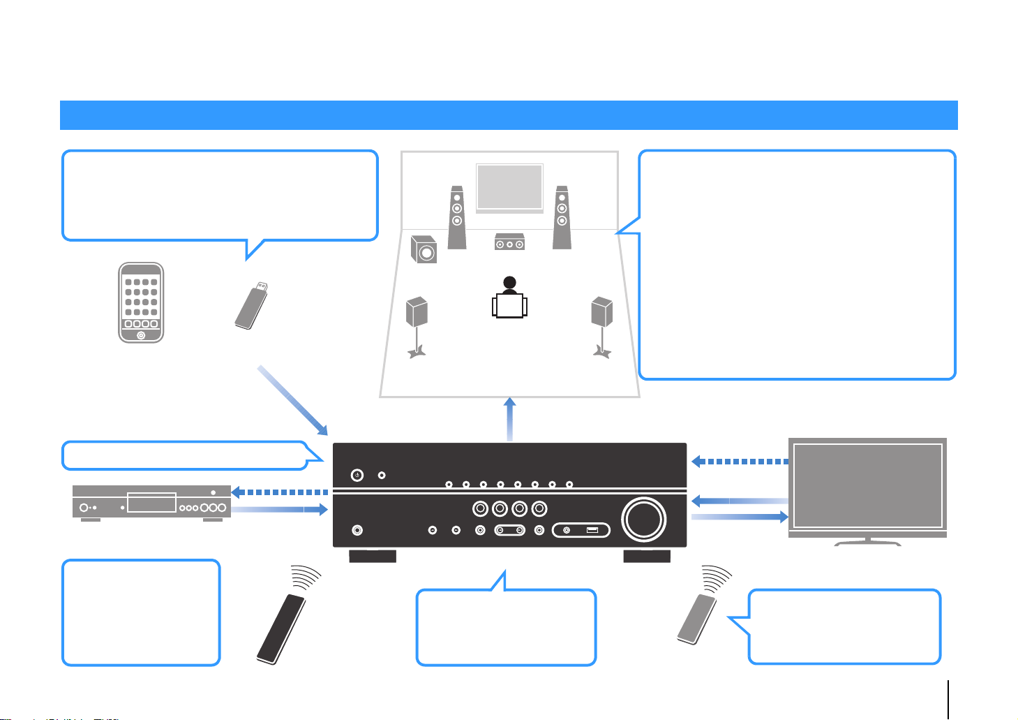
• High-quality sound from iPod via
digital connection
. p.41
• Playback of music stored on USB
storage devices
. p.45
AV receiver (the unit)
Speakers
USB storage deviceiPod
BD/DVD player
HDMI Control
Audio/Video
The unit’s
remote control
TV remote control
Audio
Audio
HDMI Control
Audio
Audio/Video
TV
Sequential operation of a TV,
AV receiver, and BD/DVD
player (HDMI Control)
. p.76
Supports 2- to 5.1-channel speaker system.
Allows you to enjoy your favorite acoustic
spaces in various styles.
• Automatically optimizing the
speaker settings to suit your room
(YPAO)
. p.26
• Reproducing stereo or multichannel
sounds with the sound fields like
actual movie theaters and concert
halls (CINEMA DSP)
. p.33
• Enjoying compressed music with
enhanced sound (Compressed
Music Enhancer)
. p.36
Change the input source
and favorite settings with
one touch (SCENE)
. p.31
The ECO mode
(power saving function)
allows you to create an
eco-friendly home
theater system
. p.61
3D and 4K Ultra HD signals supported
What you can do with the unit
FEATURES ➤ What you can do with the unit En 5
Page 6
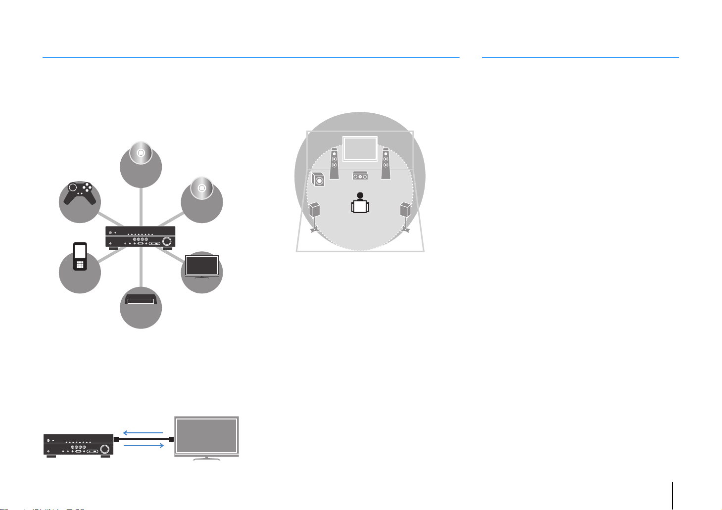
Full of useful functions!
BD/DVD
player
Game
console
Portable
audio
player
Set-top box
TV
CD player
HDMI Control
TV audio
Video from
external device
Useful tips
❑ Connecting various devices (p.20)
A number of HDMI jacks and various input/output jacks
on the unit allow you to connect video devices (such as
BD/DVD players), audio devices (such as CD players),
game consoles, portable audio player, and other
devices.
❑ Playing back TV audio in surround sound
with a single HDMI cable connection
(Audio Return Channel: ARC) (p.18)
When using an ARC-compatible TV, you only need one
HDMI cable to enable video output to the TV, audio input
from the TV, and the transmission of HDMI Control signals.
❑ Creating high-realistic sound fields (p.33)
CINEMA DSP allows you to create a natural and realistic
sound field in your own room.
❑ Surround playback with 5 speakers placed
in front (p.34)
You can enjoy the surround sound even when the
surround speakers are placed in front.
❑ Enhanced bass reproduction (p.36)
Extra Bass allows you to enjoy enhanced bass
reproduction that does not depend on the speakers
used.
❑ Listening to FM/AM radio (p.37)
The unit is equipped with a built-in FM/AM tuner. You
can register up to 40 favorite radio stations as presets.
The combination of video/audio input jacks does not
match an external device...
Use “Audio In” in the “Option” menu to change the
combination of video/audio input jacks so that it matches
the output jack(s) of your external device (p.21).
Video and audio are not synchronized...
Use “Lipsync” in the “Setup” menu to adjust the delay
between video and audio output (p.59).
I want to hear audio from the TV speakers...
Use “Audio Output” in the “Setup” menu to select the
output destination of signals input into the unit (p.57).
Your TV speakers may be selected as an output
destination.
I want to change the on-screen menu language...
Use “Language” in the “Setup” menu to select a
language from English, Japanese, French, German,
Spanish, Russian, Italian and Chinese (p.25).
I want to update the firmware...
Use “UPDATE” in the “ADVANCED SETUP” menu to
update the unit’s firmware (p.66).
Many other settings are available that let you to
customize the unit. For details, see the following pages.
• SCENE settings (p.31)
• Sound/video settings and signal information for each
source (p.48)
• Various function settings (p.52)
• System settings (p.64)
❑ Easy operation with a TV screen
You can operate the iPod or USB storage device, view
information, or easily configure the settings using the
on-screen menu.
FEATURES ➤ What you can do with the unit En 6
Page 7
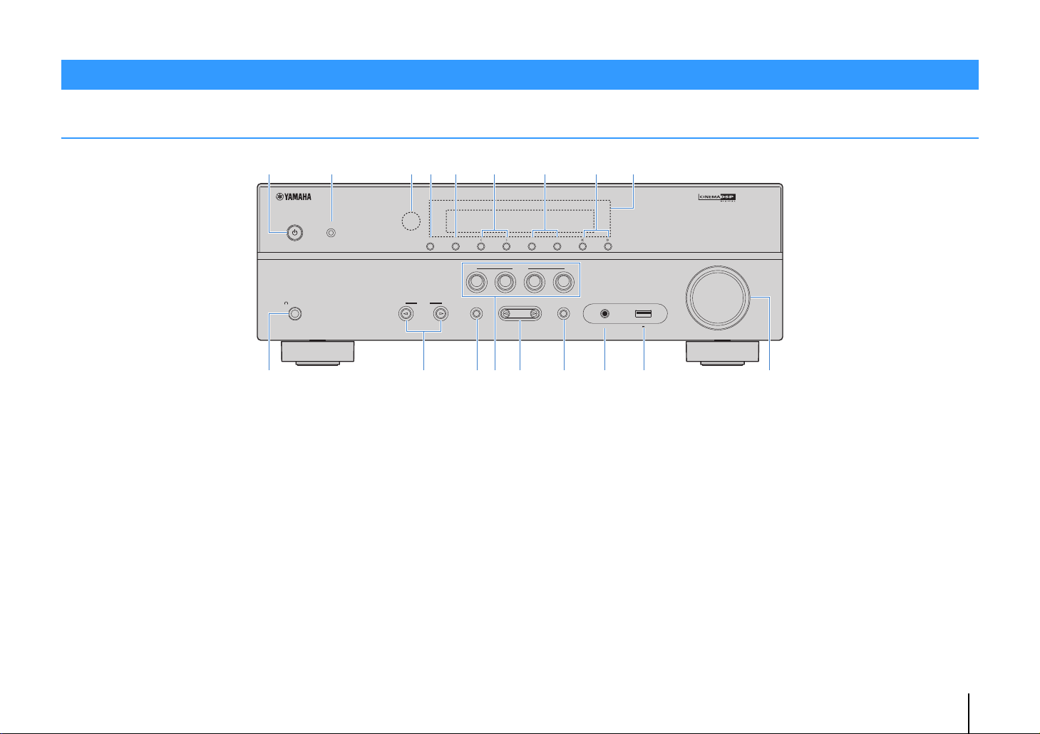
Part names and functions
YPAO MIC
INFO
MEMORY
PRESET
FM AM
TUNING
PHONES
SILENT
CINEMA
VOLUME
AUX
TONE
CONTROL
STRAIGHT
TV
BD
DVD
CD
RADIO
INPUT
PROGRAM
SCENE
AUDIO
5V 1A
394521 678
:
HBDE
GFAC
Front panel
1 z (power) key
Turns on/off (standby) the unit.
2 YPAO MIC jack
For connecting the supplied YPAO microphone (p.26).
3 Remote control sensor
Receives remote control signals (p.4).
4 INFO key
Selects the information displayed on the front display (p.30).
5 MEMORY key
Registers FM/AM radio stations as preset stations (p.38).
6 PRESET keys
Select a preset FM/AM radio station (p.39).
7 FM and AM keys
Switch between FM and AM (p.37).
8 TUNING keys
Select the radio frequency (p.37).
9 Front display
Displays information (p.8).
0 PHONES jack
For connecting headphones.
A INPUT keys
Select an input source.
B TONE CONTROL key
Adjusts the high-frequency range and low-frequency range
of output sounds (p.49).
C SCENE keys
Select the registered input source and sound program with
one touch. Also, turns on the unit when it is in standby mode
(p.31).
D PROGRAM keys
Select a sound program or a surround decoder (p.32).
E STRAIGHT key
Enables/disables the straight decode mode (p.35).
F AUX j ack
For connecting devices, such as portable audio players
(p.23).
G USB jack
For connecting a USB storage device (p.45) or an iPod
(p.41).
H VOLUME knob
Adjusts the volume.
FEATURES ➤ Part names and functions En 7
Page 8
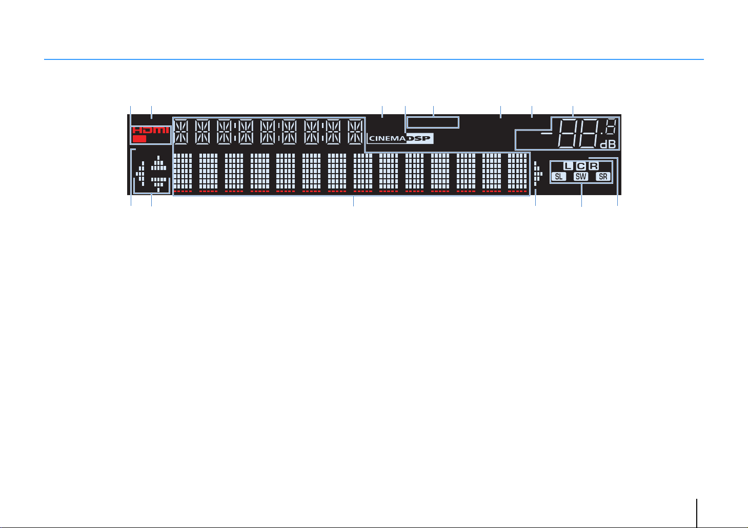
Front display (indicators)
1 2 34 6 7 8
CHARGE
OUT
ECO
SP IMP.••8 MIN
:9
1 HDMI
Lights up when HDMI signals are being input or output.
OUT
Lights up when HDMI signals are being output.
2 CHARGE
Lights up when the iPod is being charged while the unit is in
standby mode (p.41).
3 ENHANCER
Lights up when Compressed Music Enhancer (p.36) is
working.
4 CINEMA DSP
Lights up when CINEMA DSP (p.33) is working.
5 STEREO
Lights up when the unit is receiving a stereo FM radio signal.
TUNED
Lights up when the unit is receiving an FM/AM radio station
signal.
5
ENHANCER
6 SLEEP
Lights up when the sleep timer is on.
7 MUTE
Blinks when audio is muted.
8 Volume indicator
Indicates the current volume.
9 ECO
Lights up when the eco mode (p.61) is enabled.
0 Cursor indicators
Indicate the remote control cursor keys currently operational.
A Information display
Displays the current status (such as input name and sound
mode name). You can switch the information by pressing
INFO (p.30).
STEREO
TUNED
SLEEP
MUTE
VOL.
ADAPTIVE DRC
B>A
B Speaker indicators
Indicate speaker terminals from which signals are output.
A Front speaker (L)
S Front speaker (R)
D Center speaker
F Surround speaker (L)
G Surround speaker (R)
L Subwoofer
C ADAPTIVE DRC
Lights up when Adaptive DRC (p.49) is working.
C
FEATURES ➤ Part names and functions En 8
Page 9
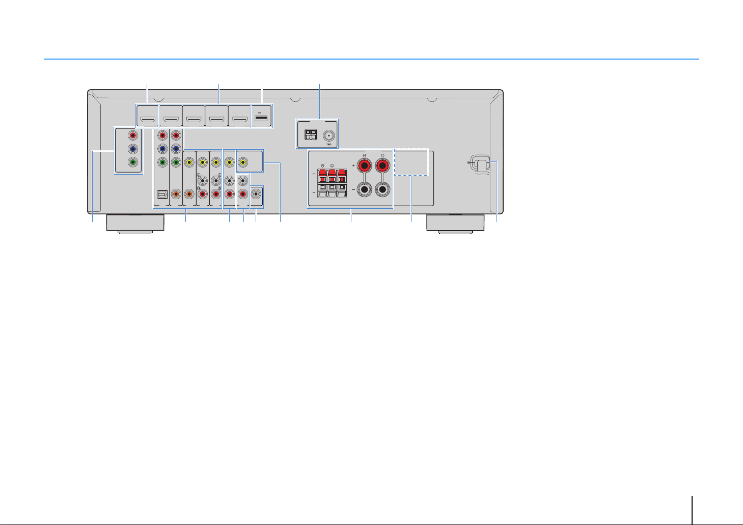
Rear panel
FRONT
AV 1
AV 2
AV 3
AV 5
OPTICAL COAXIAL COAXIAL
(
TV
)
(CD)
COMPONENT
VIDEO
P
B
Y
VIDEO
AUDIO
AV
MONITOR OUT
OUT
PRE OUT
SUBWOOFER
AV 4
COMPONENT
VIDEO
MONITOR OUT
P
R
P
B
Y
P
R
HDMI 1
(
BD/DVD
)
HDMI 2 HDMI 3
HDMI 4 DC OUT
HDMI
OUT
ARC
FM
ANTENNA
AM
SURROUND CENTER
SPEAKERS
5V 0.5A
89 A B50 C7
21
34
6
* The area around the video/audio output jacks
is marked in white on the actual product to
prevent improper connections.
1 HDMI OUT jack
For connecting to an HDMI-compatible TV and outputting
video/audio signals (p.18). When using ARC, TV audio signal
can also be input through the HDMI OUT jack.
2 HDMI 1–4 jacks
For connecting to HDMI-compatible playback devices and
inputting video/audio signals (p.20).
3 DC OUT jack
For supplying power to a Yamaha AV accessory. For details
on connections, refer to the instruction manual of the AV
accessory.
4 ANTENNA jacks
For connecting to FM and AM antennas (p.23).
5 MONITOR OUT (component video) jacks
For connecting to a TV that supports component video and
outputting video signals (p.18).
6 AV 1–5 jacks
For connecting to video/audio playback devices and
inputting video/audio signals (p.20).
7 AV OUT jacks
For outputting video/audio to a recording device (such as a
VCR) (p.24).
8 AU DIO ja cks
For connecting to audio playback devices and inputting
audio signals (p.22).
9 SUBWOOFER PRE OUT jack
For connecting to a subwoofer (with built-in amplifier) (p.15).
0 MONITOR OUT (composite video) jack
For connecting to a TV that supports composite video and
outputting video signals (p.18).
A SPEAKERS terminals
For connecting to speakers (p.15).
B VOLTAGE SELECTOR
(Taiwan and General models only)
Selects the switch position according to your local voltage
(p.24).
C Power cabl e
For connecting to an AC wall outlet (p.24).
FEATURES ➤ Part names and functions En 9
Page 10
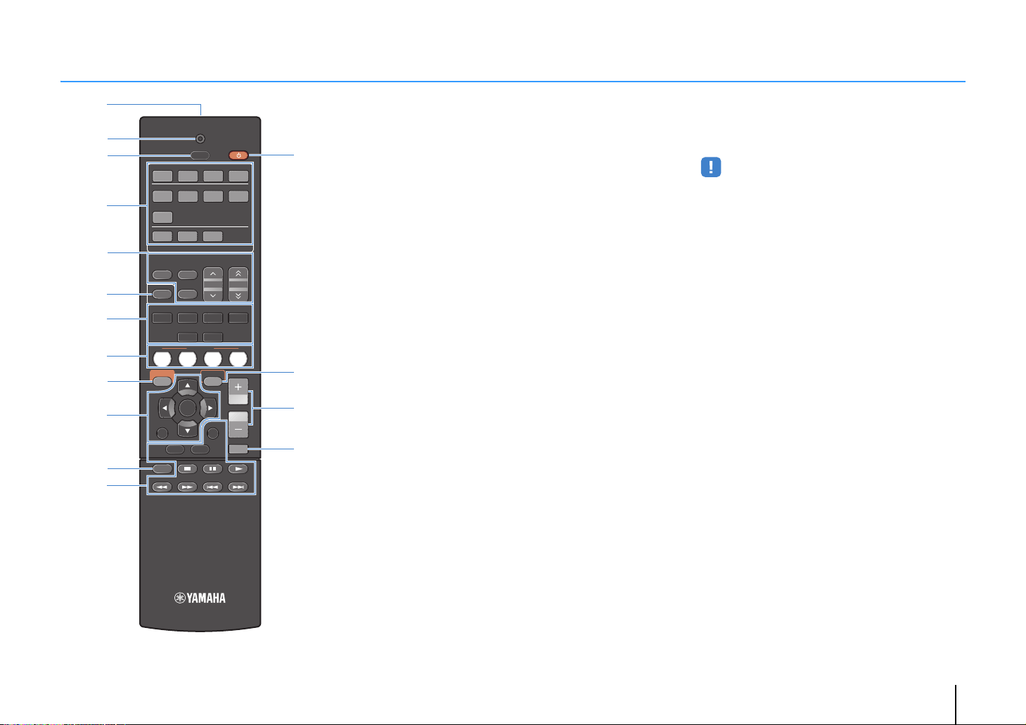
Remote control
123 4
123 4
5
FM
INFO
MEMORY
AM
PRESET
TUNING
SCENE
RETURN
TOP
MENU
POP-UP
MENU
VOLUME
BD
DVD
TV
CD
RADIO
MUTE
DISPLAY
ENTER
TRANSMIT
RECEIVER
HDMI
AV
TUNER
SLEEP
AUDIO
AUX USB
MOVIE MUSIC
SUR. DECODE STRAIGHT
ENHANCER
BASS
MODE
SETUP
OPTION
C
D
E
F
1
2
3
5
4
6
7
8
9
A
0
B
1 Remote control signal transmitter
Transmits infrared signals.
2 TRANSMIT indicator
Lights up when remote control signals are transmitted.
3 SLEEP key
Switches the unit to standby mode automatically after a
specified period of time has elapsed (sleep timer). Press
repeatedly to set the time (120 min, 90 min, 60 min, 30 min,
off).
4 Input selection keys
Select an input source for playback.
HDMI 1–4 HDMI 1–4 jacks
AV 1 – 5 AV 1–5 jacks
AUDIO AUDIO jacks
AUX AUX jack (on the front panel)
USB USB jack (on the front panel)
5 Radio keys
Operate the FM/AM radio (p.37).
FM Switches to FM radio.
AM Switches to AM radio.
MEMORY Registers FM/AM radio stations as presets.
PRESET Select a preset station.
TUNING Select the radio frequency.
6 INFO key
Selects the information displayed on the front display (p.30).
7 Sound mode keys
Select a sound mode (p.32).
8 SCENE keys
Select the registered input source and sound program with
one touch. Also, turns on the unit when it is in standby mode
(p.31).
9 SETUP key
Displays the setup menu (p.51).
0 Menu operation keys
Cursor keys Select a menu or a parameter.
ENTER Confirms a selected item.
RETURN Returns to the previous screen.
A MODE key
Switches between “Stereo” and “Mono” for FM radio
reception (p.37).
Switches the iPod operation modes (p.43).
B External device operation keys
Control playback of the iPod (p.41) or USB storage device
(p.45).
Also control playback or operate menus of the playback
devices connected to the unit with an HDMI cable.
• The playback devices must support HDMI Control. However,
Yamaha does not assure the operation of all HDMI Controlcompatible devices.
C RECEIVER z key
Turns on/off (standby) the unit.
D OPTION key
Displays the option menu (p.48).
E VOLUME keys
Adjust the volume.
F MUTE key
Mutes the audio output.
FEATURES ➤ Part names and functions En 10
Page 11

PREPARATIONS
General setup procedure
1 Placing speakers (p.12)
2 Connecting speakers (p.15)
3 Connecting a TV (p.18)
4 Connecting playback devices (p.20)
5 Connecting the FM/AM antennas (p.23)
6 Connecting recording devices (p.24)
7 Connecting the power cable (p.24)
Selecting an on-screen menu language
8
(p.25)
Optimizing the speaker settings
9
automatically (YPAO) (p.26)
This completes all the preparations. Enjoy playing movies, music, radio and other content with the unit!
Select the speaker layout for the number of speakers that you are using and place them in your room.
Connect the speakers to the unit.
Connect a TV to the unit.
Connect video devices (such as BD/DVD players) and audio devices (such as CD players) to the unit.
Connect the supplied FM/AM antennas to the unit.
Connect recording devices to the unit.
After all the connections are complete, plug in the power cable.
Select the desired on-screen menu language.
Optimize the speaker settings, such as volume balance and acoustic parameters, to suit your room
(YPAO).
PREPARATIONS ➤ General setup procedure En 11
Page 12
1 2 3 4 5 6 7 8 9
1 Placing speakers
Select the speaker layout for the number of speakers that you are using and place the speakers and subwoofer in your room. This section describes the representative speaker layout
examples.
Caution
• (U.S.A. and Canada models only)
Under its default settings, the unit is configured for 8-ohm speakers. When connecting 6-ohm speakers, set the unit’s speaker impedance to “6 Ω MIN”. For details, see “Setting the speaker impedance” (p.14).
• (Except for U.S.A. and Canada models)
Use speakers with an impedance of at least 6 Ω.
Speaker system (the number of channels)
Speaker type Abbr. Function
Front (L) 1
Front (R) 2 ●●●●●
Center 3 Produces center channel sounds (such as movie dialogue and vocals). ●● ●
Surround (L) 4
Surround (R) 5 ●●* ●
Subwoofer 9
Produce front right/left channel sounds (stereo sounds).
Produce surround right/left channel sounds.
Produces LFE (low-frequency effect) channel sounds and reinforces the bass parts of other channels.
This channel is counted as “0.1”.
5.1
●●●●●
●●* ●
●●●●●
5.1
(Virtual
CINEMA
FRONT)
4.1 3.1 2.1
* Place the surround speakers in front and set "Virtual CINEMA FRONT" (p.55) in the "Setup" menu to "On".
PREPARATIONS ➤ Placing speakers En 12
Page 13
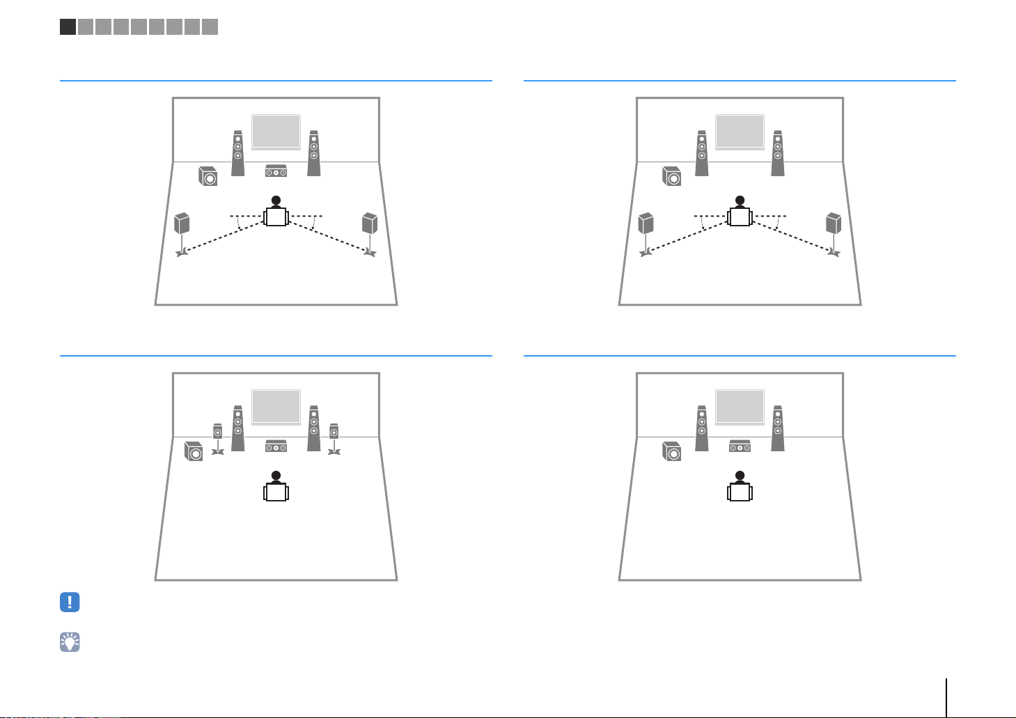
1 2 3 4 5 6 7 8 9
45
12
39
10° to 30°10° to 30°
45
12
39
45
12
9
10° to 30°10° to 30°
12
39
5.1-channel system
5.1-channel system (Virtual CINEMA FRONT)
4.1-channel system
3.1-channel system
• To utilize this configuration, set "Virtual CINEMA FRONT" (p.55) in the "Setup" menu to "On".
• You can enjoy surround sound even without the center speaker (front 4.1-channel system).
PREPARATIONS ➤ Placing speakers En 13
Page 14
12
9
z (power)
STRAIGHT
VOL.
MUTE
ENHANCER
STEREO
TUNED
SLEEP
OUT
ECO
CHARGE
ADAPTIVE DRC
VIRTUAL
SP IMP.••8¬MIN
1 2 3 4 5 6 7 8 9
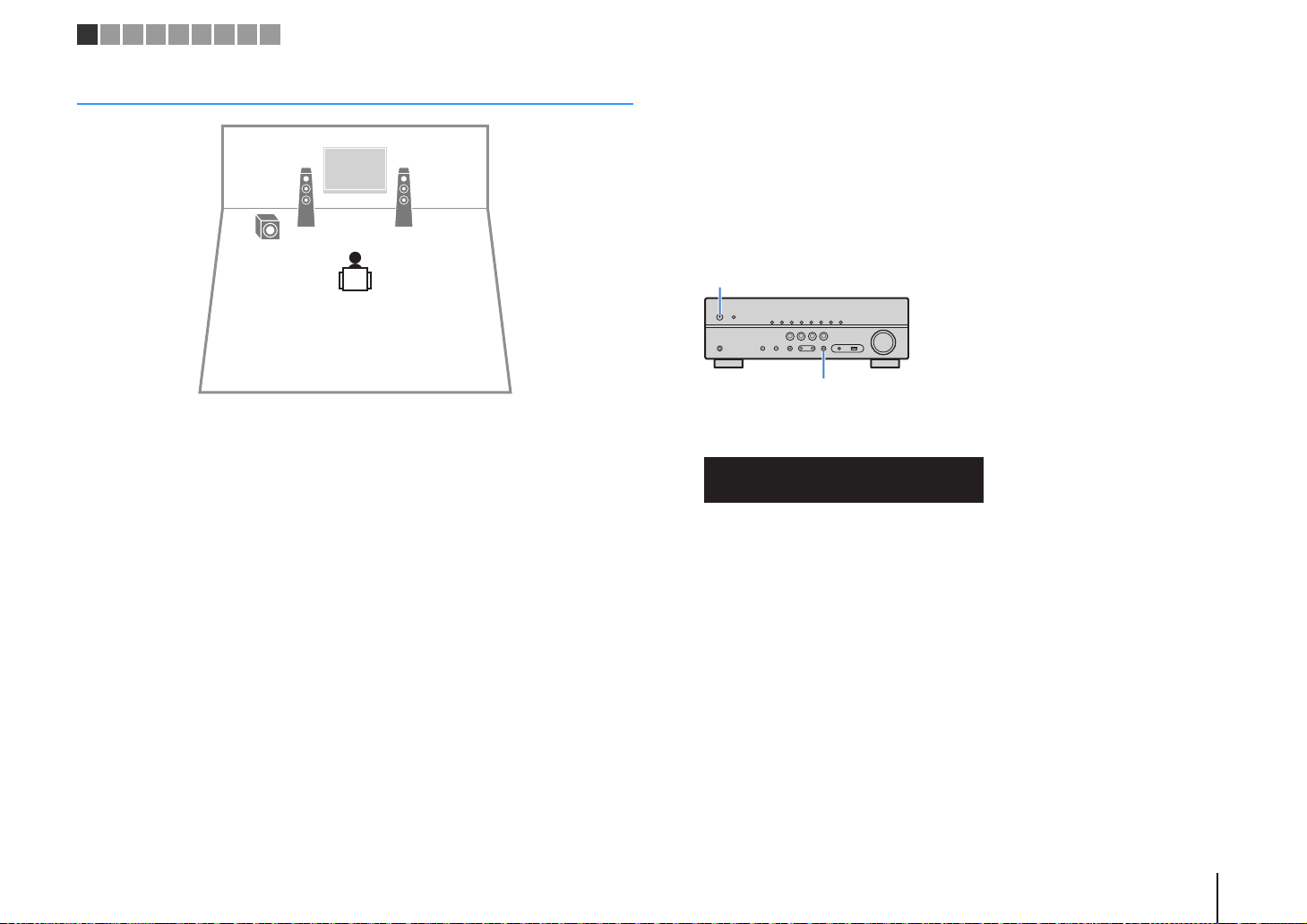
2.1-channel system
■ Setting the speaker impedance
(U.S.A. and Canada models only)
Under its default settings, the unit is configured for 8-ohm speakers. When connecting
6-ohm speakers, set the speaker impedance to “6 Ω MIN”.
Before connecting speakers, connect the power cable to an AC wall
1
outlet.
While holding down STRAIGHT on the front panel, press z (power).
2
Check that “SP IMP.” is displayed on the front display.
3
Press STRAIGHT to select “6 Ω MIN”.
4
Press z (power) to set the unit to standby mode and remove the
5
power cable from the AC wall outlet.
You are now ready to connect the speakers.
PREPARATIONS ➤ Placing speakers En 14
Page 15
–
+
–
+
FRONT
PRE OUT
SUBWOOFER
SURROUND CENTER
SPEAKERS
12
3
45
9
The unit (rear)
FRONT
aa
b
d
c
+ (red)
- (black)
FRONT
a
b
Banana plug
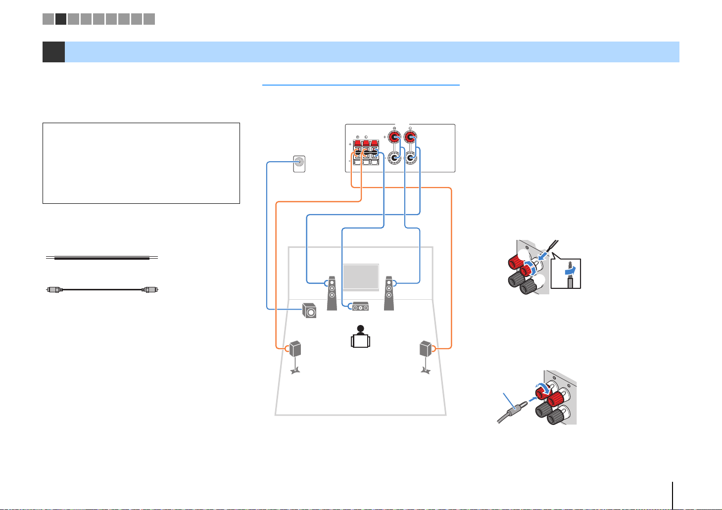
1 2 3 4 5 6 7 8 9
2 Connecting speakers
Connect the speakers placed in your room to the unit.
The following diagrams provide connections for a
5.1-channel system as an example. For other systems,
connect speakers while referring to the connection
diagram for the 5.1-channel system.
Caution
• Remove the unit’s power cable from an AC wall outlet and turn
off the subwoofer before connecting the speakers.
• Ensure that the core wires of the speaker cable do not touch
one another or come into contact with the unit’s metal parts.
Doing so may damage the unit or the speakers. If the speaker
cables short circuit, “Check SP Wires” will appear on the front
display when the unit is turned on.
Cables required for connection
(commercially available)
Speaker cables (x the number of speakers)
Audio pin cable (x1: for connecting a subwoofer)
5.1-channel system
■ Connecting speaker cables
Speaker cables have two wires. One is for connecting
the negative (-) terminal of the unit and the speaker, and
the other is for the positive (+) terminal. If the wires are
colored to prevent confusion, connect the black wire to
the negative and the other wire to the positive terminal.
(Connecting front speakers)
a Remove approximately 10 mm (3/8”) of insulation from
the ends of the speaker cable and twist the bare wires of
the cable firmly together.
b Loosen the speaker terminal.
c Insert the bare wires of the cable into the gap on the side
(upper right or bottom left) of the terminal.
d Tighten the terminal.
Using a banana plug
(U.S.A., Canada, Australia, Taiwan and General models
only)
a Tighten the speaker terminal.
b Insert a banana plug into the end of the terminal.
PREPARATIONS ➤ Connecting speakers En 15
Page 16

ROU
aa
b
c
d
+ (red)
- (black)
AV
OUT
AUDIO
Audio pin cable
1 2 3 4 5 6 7 8 9
(Connecting center/surround speakers)
a Remove approximately 10 mm (3/8”) of insulation from
the ends of the speaker cable, and twist the bare wires of
the cable firmly together.
b Press down the tab.
c Insert the bare wires of the cable into the hole in the
terminal.
d Release the tab.
ND
CENTER
■ Connecting the subwoofer
(with built-in amplifier)
Use an audio pin cable to connect the subwoofer.
PREPARATIONS ➤ Connecting speakers En 16
Page 17

Input/output jacks and cables
HDMI cable
Component video cable
Video pin cable
OPTICAL
Digital optical cable
Digital coaxial cable
Stereo pin cable
Stereo mini-plug cable
■ Video/audio jacks
❑ HDMI jacks
Transmit digital video and digital sound through a single
jack. Use an HDMI cable.
• Use a 19-pin HDMI cable with the HDMI logo. We recommend using
a cable less than 5.0 m (16.4 ft) long to prevent signal quality
degradation.
• The unit’s HDMI jacks support the HDMI Control, Audio Return
Channel (ARC), and 3D and 4K Ultra HD video transmission
(through output) features.
• Use high speed HDMI cables to enjoy 3D or 4K Ultra HD videos.
■ Video jacks
❑ COMPONENT VIDEO jacks
Transmit video signals separated into three
components: luminance (Y), chrominance blue (P
and chrominance red (P
cable with three plugs.
R). Use a component video
B),
❑ VIDEO jacks
Transmit analog video signals. Use a video pin cable.
■ Audio jacks
❑ OPTICAL jacks
Transmit digital audio signals. Use a digital optical
cable. Remove the tip protector (if available) before
using the cable.
❑ COAXIAL jacks
Transmit digital audio signals. Use a digital coaxial
cable.
❑ AUDIO jacks
(Stereo L/R jacks)
Transmit analog stereo audio signals. Use a stereo pin
cable (RCA cable).
(Stereo mini jack)
Transmits analog stereo audio signals. Use a stereo
mini-plug cable.
PREPARATIONS ➤ Input/output jacks and cables En 17
Page 18
HDMI
OUT
ARC
HDMI
HDMI
HDMI
AV 1
(TV)
OPTICAL
OPTICAL
OO
HDMI OUT jack
HDMI input
The unit (rear)
TV
AV 1 (OPTICAL) jack
Audio output
(digital optical)
M
AV 1
(TV)
OPTICAL
OPTICAL
PR
PB
Y
COMPONENT
VIDEO
OO
COMPONENT
VIDEO
MONITOR OUT
PR
PB
Y
P
R
P
B
Y
P
R
P
B
Y
The unit (rear)
Video input
(component video)
Audio output
(digital optical)
AV 1 (OPTICAL) jack
TV
MONITOR OUT
(COMPONENT VIDEO)
jacks
1 2 3 4 5 6 7 8 9
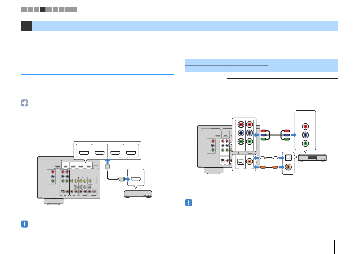
3 Connecting a TV
Connect a TV to the unit so that video input to the unit can be output to the TV. You can
also enjoy playback of TV audio on the unit.
To maximize the performance of the unit, we recommend connecting a TV with an HDMI
cable.
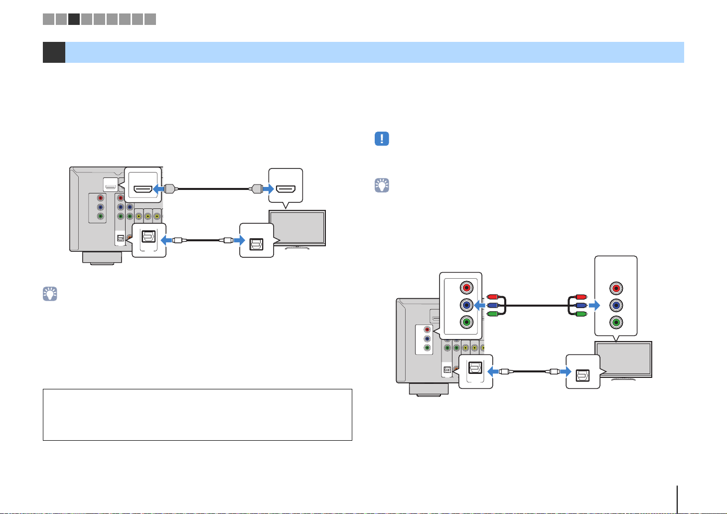
■ HDMI connection
Connect the TV to the unit with an HDMI cable and a digital optical cable.
ARC
(
)
BD/DVD
OUT
HDMI
COMPONENT
VIDEO
P
R
P
B
Y
MONITOR OUT
• You do not make a digital optical cable connection between the TV and the unit in the following cases:
– If your TV supports Audio Return Channel (ARC)
– If you will receive TV broadcasts only from the set-top box
• If you connect a TV that supports HDMI Control to the unit with an HDMI cable, you can control the unit’s
power and volume with the TV’s remote control.
To use HDMI Control and ARC, you need to configure the HDMI settings on the unit. For
details on the settings, see “Information on HDMI” (p.76).
About Audio Return Channel (ARC)
• ARC allows audio signals to travel both ways. If you connect a TV that supports ARC to the unit with a
• When using ARC, connect a TV with an HDMI cable that supports ARC.
single HDMI cable, you can output video/audio to the TV or input TV audio to the unit.
HDMI 1
P
R
P
B
Y
COMPONENT
VIDEO
OPTICAL COAXIAL COAXIAL
(
)
TV
AV 2
AV 1
HDMI 2 HDMI 3
VIDEO
(CD)
AV 4
AV 3
AV 5
■ Component / composite video connection
When connecting any video device with a component video cable, connect the TV to
the MONITOR OUT (COMPONENT VIDEO) jacks.
When connecting any video device with a video pin cable, connect the TV to the
MONITOR OUT (VIDEO) jack.
• If you connect your TV to the unit with a cable other than HDMI, video input to the unit via HDMI cannot be
output to the TV.
• Operations with TV screen are available only when your TV is connected to the unit via HDMI.
• If you will receive TV broadcasts only from the set-top box, you do not need to make an audio cable
connection between the TV and the unit.
❑ COMPONENT VIDEO connection (with a component video cable)
ARC
(
)
BD/DVD
OUT
COMPONENT
VIDEO
MONITOR OUT
HDMI
P
R
P
B
Y
HDMI 1
P
R
P
B
Y
COMPONENT
VIDEO
OPTICAL COAXIAL COAXIAL
(
)
TV
AV 2
AV 1
HDMI 2 HD
VIDEO
(CD)
AV 3
AV
AV 4
PREPARATIONS ➤ Connecting a TV En 18
Page 19
VIDEO
AV 1
(TV)
OPTICAL
OPTICAL
OO
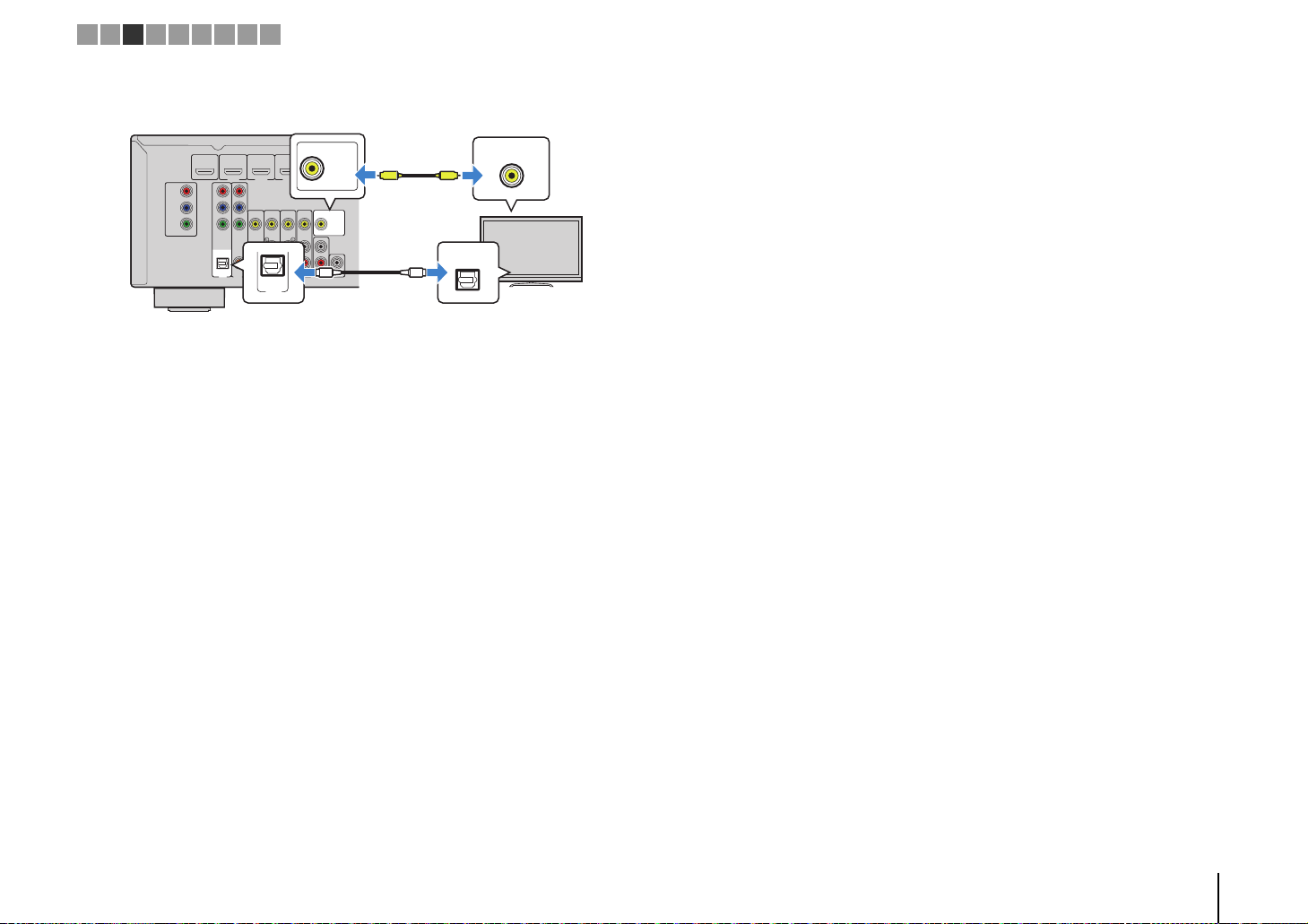
MONITOR OUT
V
V
Video input
(composite video)
The unit (rear)
TV
MONITOR OUT (VIDEO) jack
Audio output
(digital optical)
AV 1 (OPTICAL) jack
1 2 3 4 5 6 7 8 9
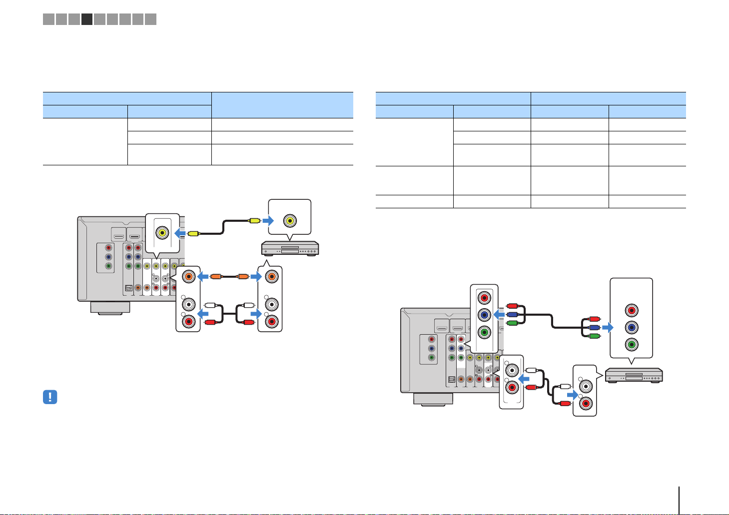
❑ VIDEO (composite video) connection (with a video pin cable)
ARC
(
)
BD/DVD
OUT
COMPONENT
VIDEO
MONITOR OUT
HDMI
P
R
P
B
Y
R
P
P
B
Y
COMPONENT
VIDEO
HDMI 2 HDMI 3
HDMI 1
VIDEO
HDMI 4 DC OUT
MONITOR OUT
OPTICAL COAXIAL COAXIAL
(
)
TV
AV 2
AV 1
AV
(CD)
OUT
AV 4
AV 5
AV 3
SUBWOOFER
PRE OUT
AUDIO
PREPARATIONS ➤ Connecting a TV En 19
Page 20
HDMI
HDMI
HDMI
HDMI 1
(
BD/DVD
)
HDMI 2 HDMI 3
HDMI 4
The unit (rear)
HDMI output
Video device
HDMI 1–4 jacks
COAXIAL
OPTICAL
P
R
P
B
Y
COMPONENT
VIDEO
OPTICAL
( TV )
COAXIAL
COMPONENT
VIDEO
P
R
P
B
Y
AV 1
AV 2
O
O
C
C
P
R
P
B
Y
P
R
P
B
Y
The unit (rear)
AV 1–2
(COMPONENT VIDEO)
jacks
Video output
(component video)
Video device
Audio output
(digital optical or digital coaxial)
AV 1 (OPTICAL) jack or
AV 2 (COAXIAL) jack
1 2 3 4 5 6 7 8 9
4 Connecting playback devices
The unit is equipped with a variety of input jacks including HDMI input jacks to allow
you to connect different types of playback devices. For information on how to connect
an iPod or a USB storage device, see the following pages.
• Connecting an iPod (p.41)
• Connecting a USB storage device (p.45)
Connecting video devices (such as BD/DVD players)
Connect video devices such as BD/DVD players, set-top boxes (STBs) and game
consoles to the unit. Depending on the video/audio output jacks available on your video
device, choose one of the following connections. We recommend using an HDMI
connection if the video device has an HDMI output jack.
• If the combination of video/audio input jacks available on the unit does not match your video device, change
its combination according to the output jacks of your device (p.21).
■ HDMI connection
Connect a video device to the unit with an HDMI cable.
ARC
(
)
BD/DVD
OUT
HDMI
COMPONENT
VIDEO
P
R
P
B
Y
MONITOR OUT
If you select the input source by pressing HDMI 1–4, the video/audio played back on
the video device will be output from the unit.
• To watch videos input to the HDMI 1–4 jacks, you need to connect your TV to the HDMI OUT jack of the
unit (p.18 to 20).
HDMI 1
P
R
P
B
Y
COMPONENT
VIDEO
OPTICAL COAXIAL COAXIAL
(
)
TV
AV 1
AV 2
HDMI 2 HDMI 3
VIDEO
(CD)
AV 3
HDMI 4 DC OUT
MONITOR OUT
SUBWOOFER
AV
PRE OUT
OUT
AUDIO
AV 5
AV 4
■ Component video connection
Connect a video device to the unit with a component video cable and an audio cable
(digital optical or digital coaxial). Choose a set of input jacks (on the unit) depending on
the audio output jacks available on your video device.
Output jacks on video device
Video Audio
Digital optical AV 1 (COMPONENT VIDEO + OPTICAL)
Component video
Digital coaxial AV 2 (COMPONENT VIDEO + COAXIAL)
Analog Stereo
ARC
(
)
BD/DVD
OUT
COMPONENT
VIDEO
MONITOR OUT
HDMI
P
R
P
B
Y
HDMI 1
P
R
P
B
Y
COMPONENT
VIDEO
OPTICAL COAXIAL COAXIAL
(
)
TV
AV 2
AV 1
HDMI 2 HDMI 3
VIDEO
(CD)
AV 3
HDMI 4 DC OUT
MONITOR OUT
SUBWOOFER
AV
PRE OUT
OUT
AUDIO
AV 5
AV 4
If you select the input source by pressing AV 1–2, the video/audio played back on the
video device will be output from the unit.
• To watch videos input to the AV 1–2 (COMPONENT VIDEO) jacks, you need to connect your TV to the
MONITOR OUT (COMPONENT VIDEO) jacks of the unit (p.18).
PREPARATIONS ➤ Connecting playback devices En 20
Input jacks on the unit
You need to change the combination of
video/audio input jacks (p.21).
Page 21
O
4
R
L
COAXIAL
R
L
COAXIAL
VIDEO
VIDEO
CC
L
R
L
R
V
V
The unit (rear)
AV 3–5 (VIDEO) jacks
Video output
(composite video)
Video device
Audio output
(digital coaxial or
analog stereo)
AV 3 (COAXIAL) jack or
AV 4–5 (AUDIO) jacks
AV 5
R
L
R
L
AUDIO
L
R
L
R
P
R
P
B
Y
COMPONENT
VIDEO
P
R
P
B
Y
P
R
P
B
Y
AV 2 (COMPONENT VIDEO) jacks
Video output
(component video)
AV 5 (AUDIO) jacks
Video device
Audio output
(analog stereo)
The unit (rear)
1 2 3 4 5 6 7 8 9
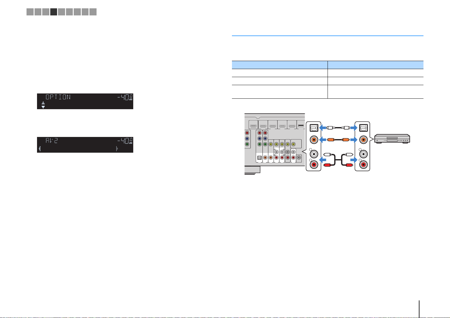
■ Composite video connection
Connect a video device to the unit with a video pin cable and an audio cable (digital
coaxial or stereo pin cable). Choose a set of input jacks (on the unit) depending on the
audio output jacks available on your video device.
Output jacks on video device
Video Audio
Digital coaxial AV 3 (VIDEO + COAXIAL)
Composite video
Analog stereo AV 4–5 (VIDEO + AUDIO)
Digital optical
ARC
(
)
BD/DVD
OUT
HDMI
COMPONENT
VIDEO
P
R
P
B
Y
MONITOR OUT
If you select the input source by pressing AV 3–5, the video/audio played back on the
video device will be output from the unit.
• To watch videos input to the AV 3–5 (VIDEO) jacks, you need to connect your TV to the MONITOR OUT
(VIDEO) jack of the unit (p.18).
HDMI 1
P
R
P
B
Y
COMPONENT
VIDEO
OPTICAL COAXIAL COAXIAL
(
)
TV
AV 2
AV 1
HDMI 2 HDMI 3
VIDEO
(CD)
AV 3
AV 4
AV 5
HDMI
M
AV
OUT
AUD
Input jacks on the unit
You need to change the combination of
video/audio input jacks (p.21).
■ Changing the combination of video/audio input jacks
If the combination of video/audio input jacks available on the unit does not match your
video device, change its combination according to the output jacks of your device. You
can connect a video device that has the following video/audio output jacks.
Output jacks on video device Input jacks on the unit
Video Audio Video Audio
Digital optical HDMI 1–4 AV 1 (OPTICAL)
HDMI
Component video Analog stereo
Composite video Digital optical AV 3–5 (VIDEO) AV 1 (OPTICAL)
❑ Necessary setting
For example, if you have connected a video device to AV 2 (COMPONENT VIDEO) and
AV 5 (AUDIO) jacks of the unit, change the combination setting as follows.
HDMI
COMPONENT
VIDEO
P
R
P
B
Y
MONITOR OUT
Digital coaxial HDMI 1–4 AV 2–3 (COAXIAL)
Analog stereo HDMI 1–4
AV 1–2
(COMPONENT
VIDEO)
ARC
(
)
BD/DVD
OUT
HDMI 1
P
R
P
B
Y
COMPONENT
VIDEO
OPTICAL COAXIAL COAXIAL
(
)
TV
AV 1
AV 2
HDMI 2 HDMI 3
VIDEO
(CD)
AV 3
HD
AV
OUT
AV 4
AV 5
PREPARATIONS ➤ Connecting playback devices En 21
AV 4–5 (AUDIO)
AUDIO
AV 4–5 (AUDIO)
AUDIO
Page 22
MUTE
ENHANCER
STEREO
TUNED
SLEEP
OUT
ECO
CHARGE
ADAPTIVE DRC
VIRTUAL
Audio In
VOL.
MUTE
ENHANCER
STEREO
TUNED
SLEEP
OUT
ECO
CHARGE
ADAPTIVE DRC
VIRTUAL
Audio••••••AV5
VOL.
N
T
R
L
COAXIAL
OPTICAL
R
L
COAXIAL
OPTICAL
CC
L
R
L
R
OO
Audio output
(either digital optical,
digital coaxial, or analog stereo)
AV 1–5 jacks
AUDIO jacks
The unit (rear)
Audio device
1 2 3 4 5 6 7 8 9
After connecting external devices (such as a TV and playback
1
devices) and power cable of the unit, turn on the unit.
Press AV 2 to select “AV 2” (video input jack to be used) as the input
2
source.
Press OPTION.
3
Use the cursor keys (q/w) to select “Audio In” and press ENTER.
4
Use the cursor keys (e/r) to select “AV 5” (audio input jack to be
5
used).
Press OPTION.
6
This completes the necessary settings.
If you select “AV 2” as the input source by pressing AV 2, the video/audio played back
on the video device will be output from the unit.
Connecting audio devices (such as CD players)
Connect audio devices such as CD players and MD players to the unit. Depending on
the audio output jacks available on your audio device, choose one of the following
connections.
Audio output jacks on audio device Audio input jacks on the unit
Digital optical AV 1 (OPTICAL)
Digital coaxial AV 2–3 (COAXIAL)
Analog stereo
ARC
(
)
BD/DVD
OUT
HDMI
T
R
B
OR OUT
HDMI 1
P
R
P
B
Y
COMPONENT
VIDEO
OPTICAL COAXIAL COAXIAL
(
)
TV
AV 2
AV 1
HDMI 2 HDMI 3
VIDEO
(CD)
AV 3
HDMI 4 DC OUT
MONITOR OUT
SUBWOOFER
AV
PRE OUT
OUT
AUDIO
AV 4
AV 5
If you select the input source by pressing AV 1–5 or AUDIO, the audio played back on
the audio device will be output from the unit.
AV 4–5 (AUDIO)
AUDIO
PREPARATIONS ➤ Connecting playback devices En 22
Page 23
Portable audio player
The unit (front)
FM antenna
AM antenna
The unit (rear)
Hold down Insert Release
1 2 3 4 5 6 7 8 9
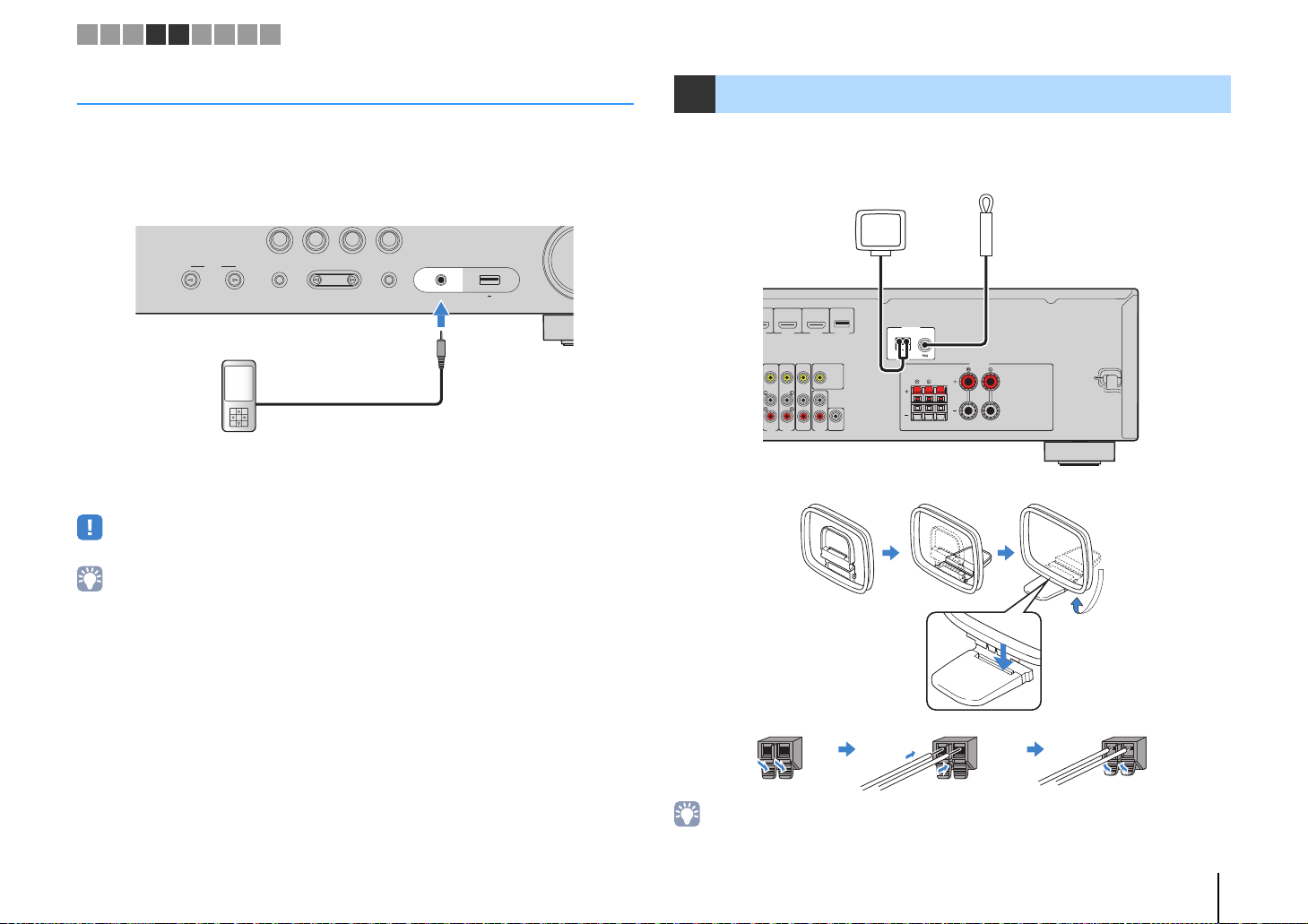
Connecting to the jack on the front panel
Use the AUX jack on the front panel to temporarily connect devices such as portable
audio players to the unit.
Before making a connection, stop playback on the device and turn down the volume on
the unit.
BD
DVD
TONE
INPUT
CONTROL
If you select “AUX” as the input source by pressing AUX, the audio played back on the
device will be output from the unit.
• You need to prepare the audio cable that matches the output jacks on your device.
• For details on how to connect an iPod or a USB storage device, see “Connecting an iPod” (p.41) or
“Connecting a USB storage device” (p.45).
CD
TV
PROGRAM
RADIO
STRAIGHT
AUX
5V 1A
AUDIO
5 Connecting the FM/AM antennas
Connect the supplied FM/AM antennas to the unit.
Fix the end of the FM antenna to a wall, and place the AM antenna on a flat surface.
HDMI 4 DC OUT
2 HDMI 3
MONITOR OUT
SUBWOOFER
AV
PRE OUT
OUT
AUDIO
AV 4
AV 5
Assembling and connecting the AM antenna
AM
ANTENNA
FM
SURROUND CENTER
SPEAKERS
FRONT
• Unwind only the length of cable needed from the AM antenna unit.
• The wires of the AM antenna have no polarity.
PREPARATIONS ➤ Connecting the FM/AM antennas En 23
Page 24

R
L
AUDIO
AV
OUT
VIDEO
V
V
L
R
L
R
The unit (rear)
AV OUT jacks
Video/audio input
Video recording
device
VOLTAGE
SELECTOR
110V
–
120V
220V
–
240V
The unit (rear)
VOLTAGE SELECTOR
To an AC wall outlet
The unit (rear)
1 2 3 4 5 6 7 8 9
6 Connecting recording devices
You can connect video/audio recording devices to the AV OUT jacks. The jacks output
analog video/audio signals selected as the input.
• To copy video/audio from a video device, connect the video device to the AV 4–5 jacks of the unit.
• To copy audio from an audio device, connect the audio device to the AV 4–5 jacks, AUDIO jacks, or AUX
jack of the unit.
• Be sure to use the AV OUT jacks only for connecting recording devices.
ARC
(
)
BD/DVD
OUT
MI
HDMI 1
P
R
P
B
Y
COMPONENT
VIDEO
VIDEO
OPTICAL COAXIAL COAXIAL
(CD)
(
)
TV
AV 2
AV 1
AV 3
HDMI 2 HDMI 3
HDMI 4 DC OUT
MONITOR OUT
SUBWOOFER
AV
PRE OUT
OUT
AUDIO
AV 4
AV 5
7 Connecting the power cable
Before connecting the power cable (Taiwan and General models only)
Set the switch position of VOLTAGE SELECTOR according to your local voltage.
Voltages are AC 110–120/220–240 V, 50/60 Hz.
• Make sure you set VOLTAGE SELECTOR of the unit BEFORE plugging the power cable into an AC
wall outlet. Improper setting of VOLTAGE SELECTOR may cause damage to the unit and create a
potential fire hazard.
ANTENNA
FM
AM
SPEAKERS
FM
SURROUND CENTER
FRONT
SPEAKERS
FRONT
SURROUND CENTER
After all the connections are complete, plug in the power cable.
ANTENNA
AM
PREPARATIONS ➤ Connecting recording devices En 24
Page 25
123 4
123 4
5
FM
INFO
MEMORY
AM
PRESET
TUNING
SCENE
RETURN
TOP
MENU
POP-UP
MENU
VOLUME
BD
DVD
TV
CD
RADIO
MUTE
DISPLAY
ENTER
TRANSMIT
RECEIVER
HDMI
AV
TUNER
SLEEP
AUDIO
AUX USB
MOVIE MUSIC
SUR. DECODE STRAIGHT
ENHANCER
BASS
MODE
SETUP
OPTION
SC
RETURN
U
UP
U
VO
T
O
MUTE
DISPLAY
A
G
INFO
3
234
5
T
T
R
S
P
O
AUX
US
C
S
S
E
Cursor keys
ENTER
RECEIVER z RECEIVER z
SETUP
Setup
Speaker
HDMI
Sound
ECO
Function
Language
English
日本語
Français
Deutsch
Español
Русский
Italiano
中文
Setup
Speaker
HDMI
Sound
ECO
Function
Language
English
日本語
Français
Deutsch
Español
Русский
Italiano
中文
1 2 3 4 5 6 7 8 9
1
AUDI
M
MOVIEMUSI
VD
TOP
MEN
MOD
TRANSMI
LEE
AV
B
UNE
M
PRESETTUNIN
MEMORY
UR. DECODESTRAIGHT
ENHANCERBAS
ENE
VCDRADI
OPTION
POP-
MEN
LUME
Cursor keys
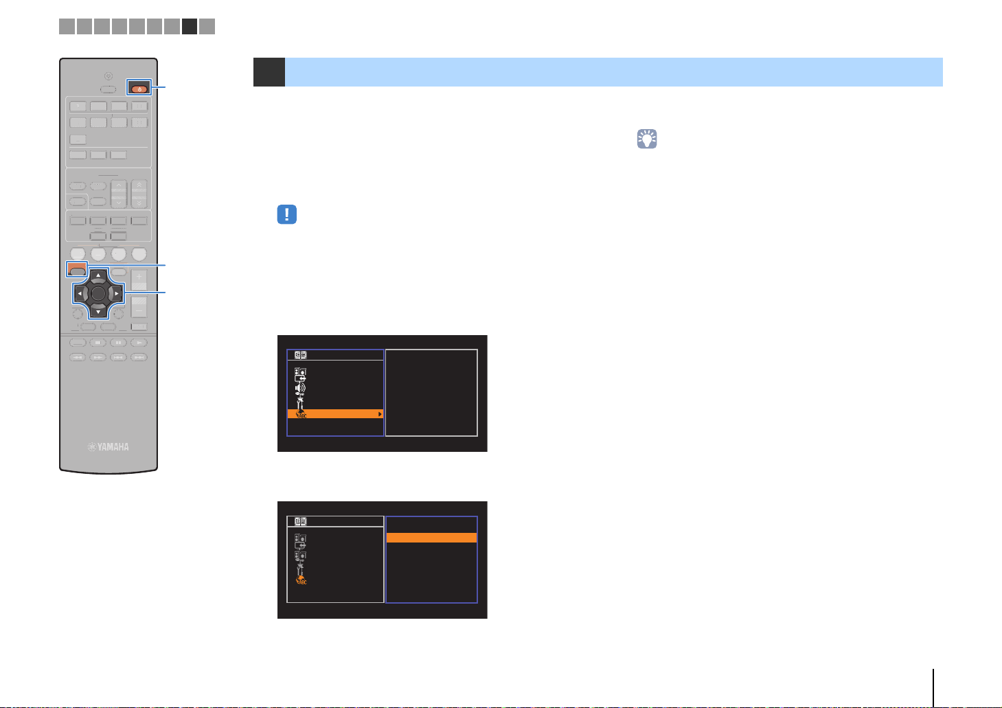
8 Selecting an on-screen menu language
Select the desired on-screen menu language from English,
Japanese, French, German, Spanish, Russian, Italian and Chinese.
Press RECEIVER z to turn on the unit.
1
Turn on the TV and switch the TV input to display
2
video from the unit (HDMI OUT jack).
• Operations with TV screen are available only when your TV is connected to
the unit via HDMI. If not, carry out operations while viewing the front display.
Press SETUP.
3
Use the cursor keys to select “Language” and press
4
ENTER.
Use the cursor keys to select the desired language.
5
To exit from the menu, press SETUP.
6
• The information on the front display is provided in English only.
PREPARATIONS ➤ Selecting an on-screen menu language En 25
Page 26
2
3
3
5
INFO
Y
P
T
T
RETU
OP
U
UP
UVOLU
BD
CDR
O
MU
Y
T
T
AV
R
S
AUDIO
AUX
USB
M
T
E
BASS
E
SETU
O
ON
VOLUME HIGH CUT
CROSSOVER/
MIN MAXMIN MAX
9
12
3
9
45
The unit (front)
Ear height
Auto Setup
Start
Exit
Press SETUP key
to Start
1 2 3 4 5 6 7 8 9
TRANSMIT
RANSMI
RECEIVER
TUNING
UNING
RADIO
ADI
VOLUME
MUTE
RECEIVER z RECEIVER z
4
ME
TE
SLEEP
LEEP
HDMI
123 4
1
AV
123 4
5
AUDIO
AUX USB
TUNE
TUNER
FM
AM
PRESET
RESE
MEMORY
MEMOR
INFO
MOVIE MUSIC
SUR. DECODE STRAIGHT
OVIE MUSIC
SUR. DECODESTRAIGH
BASS
NHANCER
ENHANCER
SCENE
SCENE
BD
TV
DVD
SETUP
RETURN
TOP
T
MENU
MEN
MODE
MOD
CD
P
PTI
OPTION
ENTER
DISPLAY
RN
DISPLA
POP-UP
POP-
MENU
MEN
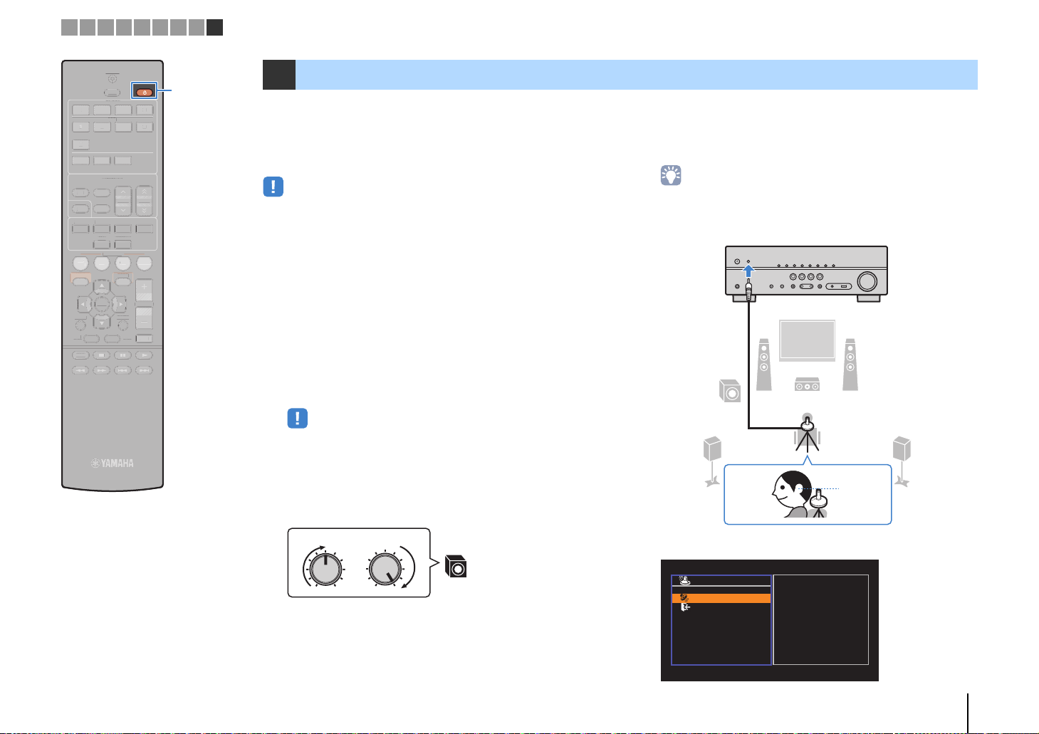
9 Optimizing the speaker settings automatically (YPAO)
The Yamaha Parametric room Acoustic Optimizer (YPAO) function
detects speaker connections, measures the distances from them to
your listening position(s), and then automatically optimizes the
speaker settings, such as volume balance and acoustic
parameters, to suit your room.
• Please note the following when using YPAO.
– Use YPAO after connecting a TV and speakers to the unit.
– During the measuring process, test tones are output at high volume. Ensure that
the test tones do not frighten small children.
– During the measuring process, you cannot adjust the volume.
– During the measuring process, keep the room as quiet as possible.
– Do not connect headphones.
– Do not stand between the speakers and the YPAO microphone during the
measurement process (about 3 minutes).
Press RECEIVER z to turn on the unit.
1
Turn on the TV and switch the TV input to display
2
video from the unit (HDMI OUT jack).
Place the YPAO microphone at your listening
4
position and connect it to the YPAO MIC jack on the
front panel.
• Place the YPAO microphone at your listening position (same height as your
ears). We recommend the use of a tripod as a microphone stand. You can
use the tripod screws to stabilize the microphone.
• Operations with TV screen are available only when your TV is connected to
the unit via HDMI. If not, carry out operations while viewing the front display.
Turn on the subwoofer and set the volume to half. If
3
the crossover frequency is adjustable, set it to
maximum.
The following screen appears on the TV.
PREPARATIONS ➤ Optimizing the speaker settings automatically (YPAO) En 26
Page 27

OP
U
UP
UVOLU
BD
CDR
O
MU
DISPLAY
Y
P
T
T
G
INFO
2
3
3
5
T
T
AV
R
S
AUDIO
AUX
USB
M
T
E
BASS
E
O
ON
1
2
3
4
Auto Setup
Start
Exit
Measurement
Finished
Result
3 / 2 / 0.1 ch
3.0 / 10.5 m
-3.0 / +10.0 dB
OK:ENTER
Auto Setup
Start
Exit
Measurement
Finished
Result
3 / 2 / 0.1 ch
3.0 / 10.5 m
-3.0 / +10.0 dB
SAVE
1 2 3 4 5 6 7 8 9
TRANSMIT
RANSMI
RECEIVER
RECEIVER
SLEEP
LEEP
HDMI
123 4
1
123 4
5
AUDIO
AUX USB
FM
AM
MEMORY
MEMOR
INFO
MOVIE MUSIC
OVIE MUSIC
BASS
BD
TV
DVD
SETUP
ENTER
RETURN
TOP
T
MENU
MEN
MODE
MOD
AV
TUNE
TUNER
PRESET
RESE
SUR. DECODE STRAIGHT
SUR. DECODESTRAIGH
NHANCER
ENHANCER
SCENE
SCENE
CD
PTI
OPTION
DISPLAY
POP-UP
POP-
MENU
MEN
TUNING
UNIN
RADIO
ADI
VOLUME
MUTE
4
TE
ME
SETUP
Cursor keys
Cursor keys
ENTER
RETURN
To start the measurement, use the cursor keys to
5
select “Start” and press SETUP.
The measurement will start in 10 seconds. Press ENTER to
start the measurement immediately.
• To stop the measurement temporarily, press RETURN and follow the
procedure in “Error messages” (p.28).
The following screen appears on the TV when the
measurement finishes.
1 The number of speakers (front side/rear side/
subwoofer)
2 Speaker distance (nearest/farthest)
3 Adjustment range of speaker output level
4 Warning message (if available)
To save the measurement results, use the cursor
6
keys (e/r) to select “SAVE” and press ENTER.
The adjusted speaker settings are applied.
• To finish the measurement without saving the result, select “CANCEL”.
Disconnect the YPAO microphone from the unit.
7
This completes optimization of the speaker settings.
Caution
• The YPAO microphone is sensitive to heat, so should not be placed anywhere
where it could be exposed to direct sunlight or high temperatures (such as on
top of AV equipment).
• If any error message (such as E-1) or warning message (such as W-1)
appears, see “Error messages” (p.28) or “Warning messages” (p.29).
• A speaker with a problem is indicated by blinking of the speaker indicators in
the front display.
• If multiple warnings are given (when operating with the front display), use
the cursor keys (q/w) to check the other warning messages.
PREPARATIONS ➤ Optimizing the speaker settings automatically (YPAO) En 27
Page 28

Error
message
Auto Setup
Start
Exit
ERROR
E-5:Noisy
PROCEED
5%
1 2 3 4 5 6 7 8 9
Error messages
If any error message is displayed during the measurement, resolve the problem and perform YPAO again.
Error message Cause Remedy
TV screen
ENHANCER
STEREO
CHARGE
OUT
ECO
TUNED
E-5:NOISY
Front display
■ Procedure to handle errors
Check the content of error message and
1
press ENTER.
Use the cursor keys (e/r) to select the
2
desired operation.
To exit the YPAO measurement:
a Select “EXIT” and press ENTER.
b Use the cursor keys (q/w) to select “Exit” and press
ENTER.
c Disconnect the YPAO microphone from the unit.
To retry the YPAO measurement from
beginning:
Select “RETRY” and press ENTER.
To proceed with the current YPAO
measurement (for E-5 and E-9 only):
Select “PROCEED” and press ENTER.
SLEEP
MUTE
VOL.
ADAPTIVE DRC
VIRTUAL
E-1:No Front SP
(E-1:NO FRNT SP)
E-2:No Sur. SP
(E-2:NO SUR SP)
E-5:Noisy
(E-5:NOISY)
E-7:No MIC
(E-7:NO MIC)
E-8:No Signal
(E-8:NO SIGNAL)
E-9:User Cancel
(E-9:CANCEL)
E-10:Internal Err.
(E-10:INTERNAL)
• Texts in parentheses denote indicators on the front display.
Front speakers are not detected.
One of the surround speakers cannot be
detected.
The noise is too loud.
The YPAO microphone has been removed.
The YPAO microphone cannot detect test
tones.
The measurement has been canceled. Retry or exit YPAO as necessary.
An internal error has occurred.
Exit YPAO, turn off the unit, and then check the speaker
connections.
Keep the room quiet and retry YPAO. If you select
“PROCEED”, YPAO takes the measurement again and
ignores any noise detected.
Connect the YPAO microphone to the YPAO MIC jack firmly
and retry YPAO.
Connect the YPAO microphone to the YPAO MIC jack firmly
and retry YPAO. If this error occurs repeatedly, contact the
nearest authorized Yamaha dealer or service center.
Exit YPAO, and turn off and on the unit. If this error occurs
repeatedly, contact the nearest authorized Yamaha dealer or
service center.
PREPARATIONS ➤ Optimizing the speaker settings automatically (YPAO) En 28
Page 29

Warning
message
Auto Setup
Start
Exit
Measurement
Finished
Result
3 / 2 / 0.1 ch
3.0 / 10.5 m
-3.0 / +10.0 dB
W-1:Out of Phase
OK:ENTER
MUTE
ENHANCER
STEREO
TUNED
SLEEP
OUT
ECO
CHARGE
ADAPTIVE DRC
VIRTUAL
W-1:PHASE
VOL.
Problem speaker (blinks)
1 2 3 4 5 6 7 8 9
Warning messages
If a warning message is displayed after the measurement, you can still save the measurement results by following on-screen instructions.
However, we recommend you perform YPAO again in order to use the unit with the optimal speaker settings.
Warning message Cause Remedy
Check the cable connections (+/-) of the problem speaker.
If the speaker is connected incorrectly:
Turn off the unit, reconnect the speaker cable.
If the speaker is connected correctly:
Depending on the type of speakers or room environment, this
message may appear even if the speakers are connected
correctly. In this case, you can ignore the message.
Exit YPAO, turn off the unit, and place the problem speaker
within 24 m (80 ft) of the listening position.
Check the usage environment and cable connections (+/-) of
each speaker, and the volume of the subwoofer. If there is
any problem, exit YPAO, turn off the unit, and then reconnect
speaker cable or correct the speaker positions. We
recommend using the same speakers or speakers with
specifications that are as similar as possible.
TV screen
Front display
■ Procedure to handle warnings
Check the content of warning message
1
and press ENTER.
W-1:Out of Phase
(W-1:PHASE)
W-2:Over Distance
(W-2:DISTANCE)
W-3:Level Error
(W-3:LEVEL)
• Texts in parentheses denote indicators on the front display.
A speaker cable may be connected with
the reverse polarity (+/-).
A speaker is placed more than 24 m (80 ft)
from the listening position.
There are significant volume differences
between the speakers.
2
3
Use the cursor keys (e/r) to select the
desired operation.
To save the measurement results:
Select “SAVE” and press ENTER.
To discard the measurement result:
Select “CANCEL” and press ENTER.
Disconnect the YPAO microphone from the
unit.
PREPARATIONS ➤ Optimizing the speaker settings automatically (YPAO) En 29
Page 30

123 4
123 4
5
FM
INFO
MEMORY
AM
PRESET
TUNING
SCENE
RETURN
TOP
MENU
POP-UP
MENU
VOLUME
BD
DVD
TV
CD
RADIO
MUTE
DISPLAY
ENTER
TRANSMIT
RECEIVER
HDMI
AV
TUNER
SLEEP
AUDIO
AUX USB
MOVIE MUSIC
SUR. DECODE STRAIGHT
ENHANCER
BASS
MODE
SETUP
OPTION
Y
P
E
RETU
TOP
U
POP-U
MENU
BD
CD
O
DIS
Y
T
RANSMIT
R
R
S
M
T
E
R
BASS
MO
SETU
O
ON
Input
selection
keys
INFO
VOLUME
MUTE
Item name
Information
LEEP
RECEIVE
PLAYBACK
TUNE
MEMOR
OVIEMUSICSUR. DECODESTRAIGH
SCEN
P
RN
MEN
DE
RESETTUNING
NHANCE
RADI
PTI
PLA
P
Input selection keys
Basic playback procedure
Turn on the external devices (such as a TV or BD/
1
DVD player) connected to the unit.
Use the input selection keys to select an input
2
source.
Start playback on the external device or select a
3
radio station.
Refer to the instruction manual for the external device.
For details on the following operations, see the
corresponding pages.
• Listening to FM/AM radio (p.37)
• Playing back iPod music (p.41)
• Playing back music stored on a USB storage device
(p.45)
Press VOLUME to adjust the volume.
4
• To mute the audio output, press MUTE. Press MUTE again to unmute.
• To adjust the treble/bass settings, use the “Option” menu or TONE
CONTROL on the front panel (p.49).
Switching information on the front display
Press INFO.
1
Each time you press the key, the displayed item changes.
CHARGE
OUT
ECO
ENHANCER
STEREO
TUNED
SLEEP
MUTE
VOL.
ADAPTIVE DRC
VIRTUAL
Audio Decoder
About 3 seconds later, the corresponding information for
the displayed item appears.
CHARGE
OUT
ECO
ENHANCER
STEREO
TUNED
SLEEP
MUTE
VOL.
ADAPTIVE DRC
VIRTUAL
†‡Pro Logic
• Available items vary depending on the selected input source. The displayed
item can also be applied separately to each input source group.
Input source group Item
HDMI 1–4
AV 1 – 5
AUDIO
AUX
USB
TUNER
* The name of the audio decoder currently activated is displayed. If no audio
decoder is activated, “Decoder Off” appears.
Input (input source name), DSP Program (sound
mode name), Audio Decoder (decoder name*)
Song (song title), Artist (artist name), Album (album
name), DSP Program (sound mode name), Audio
Decoder (decoder name*)
* During simple playback of iPod:
Input (input source name), DSP Program (sound mode
name), Audio Decoder (decoder name)
Frequency (frequency), DSP Program (sound mode
name), Audio Decoder (decoder name*)
* (U.K. and Europe models only)
Radio Data System data is also available when the unit
is tuned into a Radio Data System broadcasting station
(p.40).
PLAYBACK ➤ Basic playback procedure En 30
Page 31

TRANSMIT
4
I
MEMORY
PRES
G
RETURN
TO
MENU
MENU
MUTE
DIS
T
R
AV
TUNER
S
P
AUDIO
AUX
USB
C
S
E
BASS
MODE
S
P
N
TRANSMI
SLEEP
LEE
HDMI
1234
AV
1234
5
AUDIO
AUX USB
TUNER
FM
AM
PRESET
ET
MEMORY
INFO
NFO
MOVIE MUSIC
SUR. DECODE STRAIGHT
MOVIEMUSI
UR. DECODESTRAIGHT
BASS
NHANCER
ENHANCER
SCENE
BD
TV
DVD
SETUP
RETURN
TOP
MENU
MODE
CD
ETU
OPTIO
OPTION
ENTER
DISPLAY
PLAY
POP-UP
P
POP-UP
MENU
RECEIVER
ECEIVER
TUNING
TUNIN
RADIO
VOLUME
VOLUME
MUTE
SCENE
Selecting the input source and favorite settings with one touch (SCENE)
The SCENE function allows you to select the assigned input source,
sound program, and Compressed Music Enhancer on/off with just
one touch.
Press SCENE.
1
The input source and settings registered to the
corresponding scene are selected. The unit turns on
automatically when it is in standby mode.
By default, the following settings are registered for each scene.
SCENE Input
Sound
program
BD/DVD HDMI 1 MOVIE (Sci-Fi) Off On
TV AV 1 S TRA I GHT On On
CD AV 3 STRAIGHT Off Off
RADIO TUNER
• The SCENE link playback function allows you to automatically turn on the TV or
start playback of an external device connected to the unit via HDMI, in conjunction
with a scene selection. To enable SCENE link playback, set “SCENE” (p.58) in the
“Setup” menu to “On”.
MUSIC
(5ch Stereo)
Compressed
Music
Enhancer
SCENE link
playback
On Off
Configuring scene assignments
Perform the following operations to prepare the
1
settings you want to assign to a scene.
• Select an input source (p.30)
• Select a sound program (p.32)
• Enable/disable Compressed Music Enhancer (p.36)
Hold down the desired SCENE key until “SET
2
Complete” appears on the front display.
CHARGE
OUT
ECO
ENHANCER
STEREO
TUNED
SLEEP
MUTE
VOL.
ADAPTIVE DRC
VIRTUAL
SET Complete
PLAYBACK ➤ Selecting the input source and favorite settings with one touch (SCENE) En 31
Page 32

TRANSMIT
4
I
MEMORY
PRES
G
S
E
RETURN
TO
MENU
MENU
D
CD
O
MUTE
DIS
T
R
AV
TUNER
S
P
AUDIO
AUX
USB
MODE
S
P
N
TRANSMI
SLEEP
LEE
HDMI
1234
AV
1234
5
AUDIO
AUX USB
TUNER
FM
AM
PRESET
ET
MEMORY
INFO
NFO
MOVIE MUSIC
SUR. DECODE STRAIGHT
BASS
ENHANCER
SCENE
CEN
BD
B
TV
DVD
SETUP
RETURN
TOP
MENU
MODE
CD
ETU
OPTIO
OPTION
ENTER
DISPLAY
PLAY
POP-UP
P
POP-UP
MENU
RECEIVER
ECEIVER
TUNING
TUNIN
RADIO
RADI
VOLUME
VOLUME
MUTE
MOVIE
MUSIC
SUR.DECODE
STRAIGHT
BASS
ENHANCER
Selecting the sound mode
The unit is equipped with a variety of sound programs and
surround decoders that allow you to enjoy playback sources with
your favorite sound mode (such as sound field effect or stereo
playback).
❑ Selecting a sound program suitable for movies
• Press MOVIE repeatedly.
This mode lets you enjoy sound field effects optimized for viewing
video sources, such as movies, TV programs, and games (p.33).
❑ Selecting a sound program suitable for music or
stereo playback
• Press MUSIC repeatedly.
This mode lets you enjoy sound field effects optimized for listening
music sources or stereo playback (p.34).
❑ Selecting a surround decoder
• Press SUR.DECODE repeatedly.
This mode lets you enjoy unprocessed multichannel playback from
2-channel sources (p.35).
❑ Switching to the straight decode mode
• Press STRAIGHT.
This mode lets you enjoy unprocessed sounds in original channels
(p.35).
• You can also switch the sound programs and surround decoder by pressing
PROGRAM on the front panel.
• The sound mode can be applied separately to each input source.
• When you play back audio signals with a sampling rate of higher than 96 kHz or
playing back DTS Express, the straight decode mode (p.35) is automatically
selected.
• You can check which speakers are currently outputting sound by looking at the
speaker indicators on the unit’s front panel (p.8).
❑ Enabling Extra bass
• Press BASS.
This mode lets you enjoy enhanced bass sounds (p.36).
❑ Enabling Compressed Music Enhancer
• Press ENHANCER.
This mode lets you enjoy compressed music with additional depth
and breadth (p.36).
PLAYBACK ➤ Selecting the sound mode En 32
Page 33

Enjoying sound field effects (CINEMA DSP)
MUTE
ENHANCER
STEREO
TUNED
SLEEP
OUT
ECO
CHARGE
ADAPTIVE DRC
VIRTUAL
Sci-Fi
VOL.
Sound program category
Sound program
“CINEMA DSP” lights up
The unit is equipped with a variety of sound programs that utilize Yamaha’s original DSP
technology (CINEMA DSP). It allows you to easily create sound fields like actual movie
theaters or concert halls in your room.
• You can adjust the sound field effect level in “DSP Level” (p.49) in the “Option” menu.
■ Sound programs suitable for movies (MOVIE)
The following sound programs are optimized for viewing video sources, such as
movies, TV programs, and games.
Standard
Spectacle
Sci-Fi
Adventure
This program creates a sound field that emphasizes the surround feeling
without disturbing the original acoustic positioning of multichannel audio,
such as Dolby Digital and DTS. Its design is based on the concept of the
ideal movie theater, in which the audience is surrounded by beautiful
reverberations from the left, right, and rear.
This program delivers the scale and grandeur of spectacular movie
productions. It delivers an expansive sound space to match the
cinemascope wide-screen, and boasts a broad dynamic range, providing
everything from small delicate sounds to powerful loud booms.
This program clearly reproduces the finely elaborated sound design of the
latest Sci-Fi and SFX movies. You can enjoy a variety of
cinematographically created virtual spaces reproduced with clear
separation between dialogue, sound effects, and background music.
This program is ideal for reproducing the sound design of action and
adventure movies precisely. The sound field restrains reverberations, but
puts emphasis on reproducing a sensation of expansiveness on both sides,
powerful space expanded widely to the left and right. The restrained depth
creates a clear and powerful space, while also maintaining the articulation
of the sounds and the separation of the channels.
Drama
Mono Movie
Sports
Action Game
Roleplaying Game
This program features stable reverberations that match a wide range of
movie genres, from serious dramas to musicals and comedies. The
reverberations are modest, but suitably stereophonic. The sound effects
and background music are reproduced with a gentle echo that does not
impinge on the articulation of the dialogue. You’ll never get tired listening for
long periods.
This program reproduces monaural video sources, such as classic movies,
in an atmosphere of a good old movie theater. The program creates a
pleasant space with depth, by adding breadth and the appropriate
reverberation to the original audio.
This program allows listeners to enjoy the rich vividness of sport broadcasts
and light entertainment programs. In sports broadcasts, the commentators’
voices are positioned clearly at the center, while the atmosphere inside the
stadium is realistically conveyed by the peripheral delivery of the sounds of
the fans in a suitable space.
This program is suitable for action games, such as car racing and fighting
games. The reality of, and emphasis on, various effects makes the player
feel like they are right in the middle of the action, allowing for greater
concentration. Use this program in combination with Compressed Music
Enhancer for a more dynamic and strong sound field.
This program is suitable for role-playing and adventure games. This
program adds depth to the sound field for natural and realistic reproduction
of background music, special effects, and dialogue from a wide variety of
scenes. Use this program in combination with Compressed Music
Enhancer for a clearer and more spatial sound field.
PLAYBACK ➤ Selecting the sound mode En 33
Page 34

■ Sound programs suitable for music/stereo playback
(MUSIC)
The following sound programs are optimized for listening to music sources.
You can also select stereo playback.
This program simulates a Munich concert hall with approximately 2,500
Hall in Munich
Hall in Vienna
Chamber
Cellar Club
The Roxy Theatre
The Bottom Line
Music Video
2ch Stereo
5ch Stereo
seats that uses stylish wood for the interior finishing. Fine, beautiful
reverberations spread richly, creating a calming atmosphere. The listener’s
virtual seat is at the center left of the arena.
This program simulates a 1700-seat, middle-sized concert hall with a
shoebox shape that is traditional in Vienna. Pillars and ornate carvings
create extremely complex reverberations from all around the audience,
producing a very full, rich sound.
This program creates a relatively wide space with a high ceiling, like an
audience hall in a palace. It offers pleasant reverberations that are suitable
for courtly music and chamber music.
This program simulates an intimate concert venue with a low ceiling and
homey atmosphere. A realistic, live sound field delivers powerful sounds
that make you feel as if you are sitting in the front row in front of a small
stage.
This program creates the sound field of a 460-seat rock music concert
venue in Los Angeles. The listener’s virtual seat is at the center left of the
hall.
This program creates the sound field at stage front in The Bottom Line, a
famous New York jazz club once. The floor can seat 300 people to the left
and right in a sound field offering real and vibrant sound.
This program allows you to enjoy videos of pop, rock, and jazz concerts, as
if you were there yourself. Immerse yourself in the hot concert atmosphere
thanks to the vividness of the singers and solos on stage, a presence
sound field that emphasizes the beat of rhythm instruments, and a surround
sound field that reproduces the space of a big live hall.
Use this program to mix down multichannel sources to 2 channels. When
multichannel signals are input, they are down mixed to 2 channels and
output from the front speakers (this program does not utilize CINEMA DSP).
Use this program to output sound from all speakers. When you play back
multichannel sources, the unit mixes down the source to 2 channels, and
then outputs the sound from all speakers. This program creates a larger
sound field and is ideal for background music at parties.
■ Enjoying sound field effects without surround speakers
(Virtual CINEMA DSP)
If you select one of the sound programs (except 2ch Stereo and 5ch Stereo) when no
surround speakers are connected, the unit automatically creates the surround sound
field using the front-side speakers.
■ Enjoying surround sound with 5 speakers placed in
front (Virtual CINEMA FRONT)
You can enjoy the surround sound even when the surround speakers are placed in
front.
■ Enjoying surround sound with headphones
(SILENT CINEMA)
You can enjoy surround or sound field effects, like a multichannel speaker system, with
stereo headphones by connecting the headphones to the PHONES jack and selecting
a sound program or a surround decoder.
PLAYBACK ➤ Selecting the sound mode En 34
Page 35

1234
1234
5
FM
INFO
MEMORY
AM
PRESET
TUNING
SCENE
RETURN
TOP
MENU
POP-UP
MENU
VOLUME
BD
DVD
TV
CD
RADIO
MUTE
DISPLAY
ENTER
TRANSMIT
RECEIVER
HDMI
AV
TUNER
SLEEP
AUDIO
AUX USB
MOVIE MUSIC
SUR. DECODE STRAIGHT
ENHANCER
BASS
MODE
SETUP
OPTION
S
E
RETURN
TO
MENU
MENU
D
CD
O
MUTE
DIS
MEMORY
PRES
G
I
4
T
R
AV
TUNER
S
P
AUDIO
AUX
USB
MOVIEMUSI
C
E
BASS
MODE
S
P
N
SUR. DECODE
STRAIGHT
MUTE
ENHANCER
STEREO
TUNED
SLEEP
OUT
ECO
CHARGE
ADAPTIVE DRC
VIRTUAL
STRAIGHT
VOL.
NFO
B
ETU
P
TRANSMI
ECEIVER
LEE
ET
TUNIN
NHANCER
CEN
RADI
OPTIO
VOLUME
PLAY
POP-UP
Enjoying unprocessed playback
You can play back input sources without any sound field effect
processing.
■ Enjoying unprocessed sounds in original
channels (straight decode)
When the straight decode mode is enabled, each speaker
produces its own channel audio signal (without sound field
processing). When you play back 2-channel sources, such as a CD
player, stereo sound is heard from the front speakers. When you
play back multichannel sources, the unit produces unprocessed
multichannel sounds.
Press STRAIGHT.
1
Each time you press the key, the straight decode mode is
enabled or disabled.
■ Enjoying unprocessed multichannel
sounds (surround decoder)
The surround decoder enables unprocessed multichannel
playback from 2-channel sources. When a multichannel source is
input, it works the same way as the straight decode mode.
For details on each decoder see “Glossary” (p.73).
Press SUR.DECODE to select a surround decoder.
1
Each time you press the key, the surround decoder
changes.
CHARGE
OUT
ECO
ENHANCER
STEREO
TUNED
SLEEP
MUTE
VOL.
ADAPTIVE DRC
VIRTUAL
†‡Pro Logic
bPro Logic
bPLII Movie
bPLII Music
bPLII Game
Neo: 6 Cinema Uses the DTS Neo: 6 decoder suitable for movies.
Neo: 6 Music Uses the DTS Neo: 6 decoder suitable for music.
• You can adjust the surround decoder parameters in “DSP Parameter” (p.59)
in the “Setup” menu.
Uses the Dolby Pro Logic decoder suitable for all
sources.
Uses the Dolby Pro Logic II decoder suitable for
movies.
Uses the Dolby Pro Logic II decoder suitable for
music.
Uses the Dolby Pro Logic II decoder suitable for
games.
PLAYBACK ➤ Selecting the sound mode En 35
Page 36

1234
1234
5
FM
INFO
MEMORY
AM
PRESET
TUNING
SCENE
RETURN
TOP
MENU
POP-UP
MENU
VOLUME
BD
DVD
TV
CD
RADIO
MUTE
DISPLAY
ENTER
TRANSMIT
RECEIVER
HDMI
AV
TUNER
SLEEP
AUDIO
AUX USB
MOVIE MUSIC
SUR. DECODE STRAIGHT
ENHANCER
BASS
MODE
SETUP
OPTION
SCENE
RETURN
TO
MENU
MENU
TV
CD
O
MUTE
DIS
M
Y
PRES
G
I
4
TRANSMI
T
R
AV
TUNER
S
P
AUDIO
AUX
USB
C
S
MODE
S
P
O
ON
BASS
ENHANCER
“ENHANCER” lights up
LEE
ECEIVER
Enhancing the bass (Extra Bass)
Extra Bass allows you to enjoy enhanced bass sounds, regardless
of the size of the front speakers and the presence or absence of the
subwoofer.
Enjoying compressed music with enhanced sound (Compressed Music Enhancer)
NFO
MOVIEMUSI
ETU
P
EMOR
UR. DECODESTRAIGHT
Press BASS.
1
Each time you press the key, Extra Bass is enabled or
ET
TUNIN
RADI
PTI
VOLUME
PLAY
POP-UP
disabled.
• You can also use “Extra Bass” (p.55) in the “Setup” menu to enable/disable
Extra Bass.
Compressed Music Enhancer adds depth and breadth to the
sound, allowing you to enjoy a dynamic sound close to the original
sound before it was compressed. This function can be used along
with any other sound modes.
Press ENHANCER.
1
Each time you press the key, Compressed Music Enhancer
is enabled or disabled.
CHARGE
OUT
ECO
ENHANCER
MUTE
VOL.
ADAPTIVE DRC
VIRTUAL
SLEEP
STEREO
TUNED
Enhancer On
• Compressed Music Enhancer does not work on the following audio sources.
– Signals whose sampling rate is over 48 kHz
– High-definition streaming audio
• You can also use “Enhancer” (p.49) in the “Option” menu to enable/disable
Compressed Music Enhancer.
PLAYBACK ➤ Selecting the sound mode En 36
Page 37

123 4
123 4
5
FM
INFO
MEMORY
AM
PRESET
TUNING
SCENE
RETURN
TOP
MENU
POP-UP
MENU
VOLUME
BD
DVD
TV
CD
RADIO
MUTE
DISPLAY
ENTER
TRANSMIT
RECEIVER
HDMI
AV
TUNER
SLEEP
AUDIO
AUX USB
MOVIE MUSIC
SUR. DECODE STRAIGHT
ENHANCER
BASS
MODE
SETUP
OPTION
RETU
OP
U
UP
UVOLU
BD
CDR
O
MU
Y
Y
P
T
INFO
2
3
3
5
T
T
AV
R
S
AUDIO
AUX
USB
M
T
E
BASS
SETU
O
ON
MODE
TUNING
FM
AM
z (power)
STRAIGHTPROGRAM
VOL.
MUTE
ENHANCER
STEREO
TUNED
SLEEP
OUT
ECO
CHARGE
ADAPTIVE DRC
VIRTUAL
TU••••FM50/AM9
1
OVIE MUSIC
P
RN
T
MEN
RANSMI
LEEP
TUNE
MEMOR
SCENE
RECEIVER
RESE
SUR. DECODESTRAIGH
NHANCER
ADI
PTI
DISPLA
POP-
MEN
Listening to FM/AM radio
4
ME
TE
You can tune into a radio station by specifying its frequency or
selecting from registered radio stations.
• The radio frequencies differ depending on the country or region where the unit is
being used. The explanation of this section uses a display with frequencies used
in U.K. and Europe models.
• If you cannot obtain good reception on the radio, adjust the direction of the FM/AM
antennas.
Setting the frequency steps
(Asia, Taiwan and General models only)
At the factory, the frequency step setting is set to 50 kHz for FM and
9 kHz for AM. Depending on your listening environment, set the
frequency steps to 100 kHz for FM and 10 kHz for AM.
Set the unit to standby mode.
1
When holding down STRAIGHT on the front panel,
2
press z (power).
Press PROGRAM repeatedly to select “TU”.
3
Selecting a frequency for reception
Press FM or AM to select a band.
1
“TUNER” is selected as the input source and then the
frequency currently selected is displayed.
CHARGE
OUT
ECO
ENHANCER
STEREO
TUNED
SLEEP
MUTE
VOL.
ADAPTIVE DRC
VIRTUAL
FM 87.50MHz
Press TUNING repeatedly to set a frequency.
2
Hold down the key for about a second to search stations
automatically.
CHARGE
OUT
ECO
ENHANCER
STEREO
TUNED
SLEEP
MUTE
VOL.
ADAPTIVE DRC
VIRTUAL
FM 98.50MHz
“TUNED” lights up when a signal is received from a radio
station.
“STEREO” also lights up when a stereo signal is received.
• You can switch between “Stereo” (stereo) and “Mono” (monaural) for FM
radio reception by pressing MODE. When the signal reception for an FM
radio station is unstable, switching to monaural may improve it.
• You can watch videos input from external devices while listening to radio by
selecting the video input jack in “Video Out” (p.50) in the “Option” menu.
Press STRAIGHT to select “FM100/AM10”.
4
Press z (power) to set the unit to standby mode
5
and turn it on again.
PLAYBACK ➤ Listening to FM/AM radio En 37
Page 38

1234
1234
5
FM
INFO
MEMORY
AM
PRESET
TUNING
SCENE
RETURN
TOP
MENU
POP-UP
MENU
VOLUME
BD
DVD
TV
CD
RADIO
MUTE
DISPLAY
ENTER
TRANSMIT
RECEIVER
HDMI
AV
TUNER
SLEEP
AUDIO
AUX USB
MOVIE MUSIC
SUR. DECODE STRAIGHT
ENHANCER
BASS
MODE
SETUP
OPTION
S
E
TO
MENU
POP-U
MENU
D
CD
O
G
4
MUTE
DISPLAY
TRANSMI
T
R
AV
TUNER
S
P
AUDIO
AUX
USB
C
S
E
BASS
MODE
S
P
ENTER
RETURN
MEMORY
PRESET
FM
AM
OPTION
MUTE
ENHANCER
STEREO
TUNED
SLEEP
OUT
ECO
CHARGE
ADAPTIVE DRC
VIRTUAL
Auto Preset
VOL.
MUTE
ENHANCER
STEREO
TUNED
SLEEP
OUT
ECO
CHARGE
ADAPTIVE DRC
VIRTUAL
01:FM 87.50MHz
VOL.
“SEARCH” appears during Auto Preset
Preset number from which to start the registration
MUTE
ENHANCER
STEREO
TUNED
SLEEP
OUT
ECO
CHARGE
ADAPTIVE DRC
VIRTUAL
Auto Preset
VOL.
Preset number
“Empty” (not in use) or the frequency currently registered
LEE
ECEIVER
Registering favorite radio stations (presets)
You can register up to 40 radio stations as presets. Once you have
registered stations, you can easily tune into them by selecting their
preset numbers.
When the Auto Preset process finishes, “FINISH” appears and the
“Option” menu closes automatically.
INFO
MOVIEMUSI
B
ETU
P
UR. DECODESTRAIGHT
NHANCER
CEN
P
TUNIN
RADI
VOLUME
Cursor keys
■ Registering radio stations automatically
(Auto Preset)
Automatically register FM radio stations with strong signals (up to
40 stations).
• To register AM radio stations, follow “Registering a radio station manually”.
• (U.K. and Europe models only)
Only Radio Data System broadcasting stations are stored automatically by the
Auto Preset function.
Press FM or AM to select “TUNER” as the input source.
1
Press OPTION.
2
Use the cursor keys to select “Auto Preset”.
3
To start the Auto Preset process, press ENTER.
4
The registration will start in 5 seconds. Press ENTER again
to start the registration immediately.
■ Registering a radio station manually
Select a radio station manually and register it to a preset number.
Follow “Selecting a frequency for reception” (p.37)
1
to tune into the desired radio station.
Hold down MEMORY for more than 2 seconds.
2
The first time that you do register a station, the selected
radio station will be registered to the preset number “01”.
Thereafter, each radio station you select will be registered
to the next empty (unused) preset number after the most
recently registered number.
CHARGE
OUT
ECO
ENHANCER
STEREO
TUNED
SLEEP
MUTE
VOL.
ADAPTIVE DRC
VIRTUAL
01:FM 98.50MHz
• To select a preset number for registering, press MEMORY once after tuning
into the desired radio station, press PRESET to select a preset number, and
then press MEMORY again.
CHARGE
OUT
ECO
ENHANCER
STEREO
TUNED
SLEEP
MUTE
VOL.
ADAPTIVE DRC
VIRTUAL
02:Empty
• To specify the preset number from which to start the registration, press
PRESET or cursor keys (q/w) to select a preset number within 5 seconds
after step 4 (while “READY” is displayed) and then press ENTER (or just
wait for 5 seconds).
• To cancel the Auto Preset process, press RETURN.
PLAYBACK ➤ Listening to FM/AM radio En 38
Page 39

1234
1234
5
FM
INFO
MEMORY
AM
PRESET
TUNING
SCENE
RETURN
TOP
MENU
POP-UP
MENU
VOLUME
BD
DVD
TV
CD
RADIO
MUTE
DISPLAY
ENTER
TRANSMIT
RECEIVER
HDMI
AV
TUNER
SLEEP
AUDIO
AUX USB
MOVIE MUSIC
SUR. DECODE STRAIGHT
ENHANCER
BASS
MODE
SETUP
OPTION
RETURN
OP
MENU
POP-UP
MENU
V
B
CD
R
O
MUTE
DISPLAY
O
TU
G
4
TRANSMI
T
AV
TUNER
S
AUDIO
AUX
USB
MOVIE
MUSIC
S
BASS
MODE
S
P
ENTER
PRESET
FM
AM
OPTION
MUTE
ENHANCER
SLEEP
OUT
ECO
CHARGE
ADAPTIVE DRC
VIRTUAL
01:FM 98.50MHz
STEREO
TUNED
VOL.
Preset station to be cleared
LEEP
RECEIVER
■ Selecting a preset station
Tune into a registered radio station by selecting its preset number.
■ Clearing preset stations
Clear radio stations registered to the preset numbers.
INF
D
ETU
T
MEMORY
SCENE
UR. DECODESTRAIGHT
ENHANCER
ADI
OLUME
NIN
Cursor keys
Press FM or AM to select “TUNER” as the input
1
source.
Press PRESET repeatedly to select the desired radio
2
station.
• “No Presets” appears when no radio stations are registered.
Press FM or AM to select “TUNER” as the input
1
source.
Press OPTION.
2
Use the cursor keys to select “Clear Preset” and
3
press ENTER.
CHARGE
OUT
ECO
ENHANCER
STEREO
TUNED
SLEEP
MUTE
VOL.
ADAPTIVE DRC
VIRTUAL
Clear Preset
Use the cursor keys (q/w) to select a preset station
4
to be cleared and press ENTER.
CHARGE
OUT
ECO
ENHANCER
STEREO
TUNED
SLEEP
MUTE
VOL.
ADAPTIVE DRC
VIRTUAL
01:FM 98.50MHz
If the preset station is cleared, “Cleared” appears and then
the next in-use preset number is displayed.
CHARGE
OUT
ECO
ENHANCER
STEREO
TUNED
SLEEP
MUTE
VOL.
ADAPTIVE DRC
VIRTUAL
01:Cleared
Repeat step 4 until all desired preset stations are
5
cleared.
To exit from the menu, press OPTION.
6
PLAYBACK ➤ Listening to FM/AM radio En 39
Page 40

TRANSMIT
S
E
TO
MENU
POP-U
MENU
D
CD
O
MUTE
DISPLAY
Y
PRES
G
4
T
R
AV
TUNER
S
P
AUDIO
AUX
USB
C
S
E
BASS
MODE
S
P
MUTE
ENHANCER
SLEEP
OUT
ECO
CHARGE
ADAPTIVE DRC
VIRTUAL
Program Type
STEREO
TUNED
VOL.
Item name
MUTE
ENHANCER
SLEEP
OUT
ECO
CHARGE
ADAPTIVE DRC
VIRTUAL
CLASSICS
STEREO
TUNED
VOL.
Information
Traffic information station (frequency)
TRANSMI
SLEEP
LEE
HDMI
1234
AV
1234
5
AUDIO
AUX USB
TUNER
FM
AM
PRESET
ET
MEMORY
MEMOR
INFO
MOVIE MUSIC
SUR. DECODE STRAIGHT
MOVIEMUSI
UR. DECODESTRAIGHT
BASS
NHANCER
ENHANCER
SCENE
CEN
BD
B
TV
DVD
SETUP
RETURN
TOP
MENU
MODE
CD
ETU
OPTION
ENTER
DISPLAY
POP-UP
P
MENU
P
RECEIVER
ECEIVER
TUNING
TUNIN
RADIO
RADI
VOLUME
VOLUME
MUTE
INFO
OPTION
Cursor keys
Cursor keys
ENTER
RETURN
Radio Data System tuning
(U.K. and Europe models only)
Radio Data System is a data transmission system used by FM
stations in many countries. The unit can receive various types of
Radio Data System data, such as “Program Service”, “Program
Type,” “Radio Text” and “Clock Time”, when it is tuned into a Radio
Data System broadcasting station.
■ Displaying the Radio Data System
information
Tune into the desired Radio Data System
1
broadcasting station.
• We recommend using “Auto Preset” to tune into the Radio Data System
broadcasting stations (p.38).
Press INFO.
2
Each time you press the key, the displayed item changes.
About 3 seconds later, the corresponding information for
the displayed item appears.
• “Program Service”, “Program Type”, “Radio Text”, and “Clock Time” are not
displayed if the radio station does not provide the Radio Data System
service.
■ Receiving traffic information
automatically
When “TUNER” is selected as the input source, the unit
automatically receives traffic information. To enable this function,
follow the procedure below to set the traffic information station.
When “TUNER” is selected as the input source,
1
press OPTION.
Use the cursor keys to select “Traffic Program”
2
(TrafficProgram) and press ENTER.
The traffic information station search will start in 5 seconds.
Press ENTER again to start the search immediately.
• To search upward/downward from the current frequency, press the cursor
keys (q/w) while “READY” is displayed.
• To cancel the search, press RETURN.
• Texts in parentheses denote indicators on the front display.
The following screen appears for about 3 seconds when the
search finishes.
CHARGE
OUT
ECO
ENHANCER
STEREO
TUNED
SLEEP
MUTE
VOL.
ADAPTIVE DRC
VIRTUAL
TP FM101.30MHz
Program Service Program service name
Program Type Current program type
Radio Text Information on the current program
Clock Time Current time
DSP Program Sound mode name
Audio Decoder Decoder name
Frequency Frequency
• “TP Not Found” appears for about 3 seconds when no traffic information
stations are found.
PLAYBACK ➤ Listening to FM/AM radio En 40
Page 41

123 4
123 4
5
FM
INFO
MEMORY
AM
PRESET
TUNING
SCENE
RETURN
TOP
MENU
POP-UP
MENU
VOLUME
BD
DVD
TV
CD
RADIO
MUTE
DISPLAY
ENTER
TRANSMIT
RECEIVER
HDMI
AV
TUNER
SLEEP
AUDIO
AUX USB
MOVIE MUSIC
SUR. DECODE STRAIGHT
ENHANCER
BASS
MODE
SETUP
OPTION
2
3
3
5
INFO
Y
P
T
T
G
RETU
OP
U
UP
UVOLU
BD
CDR
O
MU
Y
T
T
AV
R
S
AUDIO
AUX
M
T
E
BASS
E
SETU
O
ON
USBUSB
The unit (front)
MUTE
ENHANCER
STEREO
TUNED
SLEEP
OUT
ECO
CHARGE
ADAPTIVE DRC
VIRTUAL
iPod Connected
VOL.
1/2
Music
Videos
iPod
Top
1
OVIE MUSIC
P
RN
T
MEN
MOD
RANSMI
LEEP
TUNE
MEMOR
SCENE
RECEIVER
RESE
UNIN
SUR. DECODESTRAIGH
NHANCER
ADI
PTI
DISPLA
POP-
MEN
Playing back iPod music
4
ME
TE
You can play back iPod music on the unit using a USB cable
supplied with the iPod.
• You cannot play back iPod video on the unit.
• For details on playable iPod devices, see “Supported devices and file formats”
(p.75).
Connecting an iPod
Connect your iPod to the unit with the USB cable supplied with the
iPod.
Connect the USB cable to the iPod.
1
Connect the USB cable to the USB jack.
2
RADIO
STRAIGHT
AUX
5V 1A
AUDIO
Playback of iPod content
Follow the procedure below to operate the iPod contents and start
playback.
You can control the iPod with the menu displayed on the TV screen.
• Operations with TV screen are available only when your TV is connected to the
unit via HDMI. If not, carry out operations while viewing the front display, or directly
operate the iPod itself in the simple play mode (p.43).
• “_” (underscore) will be displayed for characters not supported by the unit.
Press USB to select “USB” as the input source.
1
The browse screen is displayed on the TV.
• If playback is ongoing on your iPod, the playback screen is displayed.
• The iPod charges while it is connected to the unit. If you set the unit to standby
mode while the iPod is connected, the iPod continues to charge (up to 4 hours).
• Disconnect the iPod from the USB jack when it is not in use.
PLAYBACK ➤ Playing back iPod music En 41
Page 42

1234
1234
5
FM
INFO
MEMORY
AM
PRESET
TUNING
SCENE
RETURN
TOP
MENU
POP-UP
MENU
VOLUME
BD
DVD
TV
CD
RADIO
MUTE
DISPLAY
ENTER
TRANSMIT
RECEIVER
HDMI
AV
TUNER
SLEEP
AUDIO
AUX USB
MOVIE MUSIC
SUR. DECODE STRAIGHT
ENHANCER
BASS
MODE
SETUP
OPTION
OP
MENU
POP-UP
MENU
V
B
CD
R
O
MUTE
T
TU
G
O
4
T
AV
TUNER
S
AUDIO
AUX
USB
MOVIE
MUSIC
S
BASS
MODE
S
P
O
Cursor keys
ENTER
RETURN
DISPLAY
Artist Name
Album Title
Song Title
2:30
iPod
Now Playing
5:10
[DISPLAY] to List Browse
1
4
5
2
3
Playlists
Artists
Albums
Songs
Genres
Composers
iPod
Music
[DISPLAY] to Now Playing
1/6
INF
D
ETU
T
TRANSMI
LEEP
MEMORY
SCENE
RECEIVER
PRESE
NIN
UR. DECODESTRAIGHT
ENHANCER
ADI
PTION
OLUME
Cursor keys
Use the cursor keys to select an item and press
2
ENTER.
If a song is selected, playback starts and the playback
screen is displayed.
• To return to the previous screen, press RETURN.
• To switch between the browse and playback screens during playback, press
DISPLAY.
• To operate the iPod manually to select content or control playback, switch to
the simple play mode (p.43).
■ Browse screen
1 List name
2 Contents list
Displays the list of iPod content. Use the cursor keys to select an item and
press ENTER to confirm the selection.
3 Item number/total
4 Status indicators
Display the current repeat/shuffle settings (p.44) and playback status
(such as play/pause).
5 Operation menu
Press the cursor key (r) and then use the cursor keys (q/w) to select an
item. Press ENTER to confirm the selection.
Icon Function
Moves 10 pages backward.
Moves to the previous page of the list.
Moves to the next page of the list.
Moves 10 pages forward.
Moves to the playback screen.
PLAYBACK ➤ Playing back iPod music En 42
Page 43

TRANSMIT
S
E
TO
MENU
POP-U
MENU
D
CD
O
MUTE
DISPLAY
T
R
S
P
Y
PRES
G
TUNER
4
AV
AUDIO
AUX
USB
C
S
E
BASS
S
P
N
1
2
iPod
Now Playing
Artist Name
Album Title
Song Title
2:30
5:10
[DISPLAY] to List Browse
TRANSMI
SLEEP
LEE
HDMI
1234
AV
1234
5
AUDIO
AUX USB
TUNER
FM
AM
PRESET
ET
MEMORY
MEMOR
INFO
INFO
MOVIE MUSIC
SUR. DECODE STRAIGHT
MOVIEMUSI
UR. DECODESTRAIGHT
BASS
NHANCER
ENHANCER
SCENE
CEN
BD
B
TV
DVD
SETUP
RETURN
TOP
MENU
MODE
CD
ETU
OPTIO
OPTION
ENTER
DISPLAY
POP-UP
P
MENU
P
RECEIVER
ECEIVER
TUNING
TUNIN
RADIO
RADI
VOLUME
VOLUME
MUTE
Cursor keys
ENTER
RETURN
MODE
External device
operation keys
■ Playback screen
1 Status indicators
Display the current repeat/shuffle settings (p.44) and playback status
(such as play/pause).
2 Playback information
Displays the artist name, album name, song title, and elapsed time/song
length.
Use the following remote control keys to control playback.
External device
operation keys
a Resumes playback from pause.
s Stops playback.
d Stops playback temporarily.
f
g
h
j
Function
Skips forward/backward.
Searches forward/backward (by holding down).
■ Operating the iPod itself or remote control
(simple play)
Press MODE to switch to the simple play mode.
1
The TV menu screen turns off and iPod operations are
enabled.
To display the TV menu screen, press MODE again.
Operate your iPod itself or the remote control to
2
start playback.
Operational remote control
keys
Cursor keys Select an item.
ENTER Confirms the selection.
RETURN Returns to the previous screen.
External device
operation keys
Function
a
Starts playback or stops playback
temporarily.
d
s Stops playback.
f
Skips forward/backward.
g
h
Searches forward/backward (by holding
down).
j
PLAYBACK ➤ Playing back iPod music En 43
Page 44

TRANSMIT
S
E
TO
MENU
MENU
D
CD
O
MUTE
DISPLAY
MEMORY
PRES
G
I
4
T
R
AV
TUNER
S
P
AUDIO
AUX
USB
C
S
E
BASS
S
P
TRANSMI
SLEEP
LEE
HDMI
1234
AV
1234
5
AUDIO
AUX USB
TUNER
FM
AM
PRESET
ET
MEMORY
INFO
NFO
MOVIE MUSIC
SUR. DECODE STRAIGHT
MOVIEMUSI
UR. DECODESTRAIGHT
BASS
NHANCER
ENHANCER
SCENE
CEN
BD
B
TV
DVD
SETUP
RETURN
TOP
MENU
MODE
CD
ETU
OPTION
ENTER
DISPLAY
POP-UP
P
POP-UP
MENU
RECEIVER
ECEIVER
TUNING
TUNIN
RADIO
RADI
VOLUME
VOLUME
MUTE
OPTION
Cursor keys
ENTER
RETURN
MODE
■ Repeat/shuffle settings
You can configure the repeat/shuffle settings of your iPod.
• During simple play, configure the repeat/shuffle settings directly on your iPod or
press MODE to display the TV menu screen and then follow the procedure below.
When “USB” is selected as the input source, press
1
OPTION.
Use the cursor keys to select “Repeat” (Repeat) or
2
“Shuffle” (Shuffle) and press ENTER.
• To return to the previous screen during menu operations, press RETURN.
• Texts in parentheses denote indicators on the front display.
Use the cursor keys (e/r) to select a setting.
3
Item Setting Function
Off (Off) Turns off the repeat function.
Repeat
(Repeat)
Shuffle
(Shuffle)
One (One)
All (All)
Off (Off) Turns off the shuffle function.
Songs
(Songs)
Albums
(Albums)
Plays back the current song repeatedly.
“c” appears in the TV screen.
Plays back all songs repeatedly.
“v” appears in the TV screen.
Plays back songs in random order.
“x” appears in the TV screen.
Plays back albums in random order.
“x” appears in the TV screen.
To exit from the menu, press OPTION.
4
PLAYBACK ➤ Playing back iPod music En 44
Page 45

123 4
123 4
5
FM
INFO
MEMORY
AM
PRESET
TUNING
SCENE
RETURN
TOP
MENU
POP-UP
MENU
VOLUME
BD
DVD
TV
CD
RADIO
MUTE
DISPLAY
ENTER
TRANSMIT
RECEIVER
HDMI
AV
TUNER
SLEEP
AUDIO
AUX USB
MOVIE MUSIC
SUR. DECODE STRAIGHT
ENHANCER
BASS
MODE
SETUP
OPTION
2
3
3
5
INFO
Y
P
T
T
G
RETU
OP
U
UP
UVOLU
BD
CDR
O
MU
Y
T
T
AV
R
S
AUDIO
AUX
M
T
E
BASS
E
SETU
O
ON
USBUSB
The unit (front)
USB storage device
MUTE
ENHANCER
STEREO
TUNED
SLEEP
OUT
ECO
CHARGE
ADAPTIVE DRC
VIRTUAL
USB Connected
VOL.
1/12
Blues
Classical
Electronica
Jazz
Pop
Rock
Soundtrack
Speaking
USB
Top
1
OVIE MUSIC
P
RN
T
MEN
MOD
RANSMI
LEEP
TUNE
MEMOR
SCENE
RECEIVER
RESE
UNIN
SUR. DECODESTRAIGH
NHANCER
ADI
PTI
DISPLA
POP-
MEN
Playing back music stored on a USB storage device
4
ME
TE
You can play back music files stored on a USB storage device on
the unit.
• For details on playable USB devices, see “Supported devices and file formats”
(p.75).
Connecting a USB storage device
Connect the USB storage device to the USB jack.
1
RADIO
STRAIGHT
AUX
5V 1A
AUDIO
Playback of USB storage device contents
Follow the procedure below to operate the USB storage device
contents and start playback.
You can control the USB memory device with the menu displayed
on the TV screen.
• Operations with TV screen are available only when your TV is connected to the
unit via HDMI. If not, carry out operations while viewing the front display.
• “_” (underscore) will be displayed for characters not supported by the unit.
Press USB to select “USB” as the input source.
1
The browse screen is displayed on the TV.
• If playback is ongoing on your USB storage device, the playback screen is
displayed.
• If the USB storage device contains many files, it may take time to load the them. In
this case, “Loading...” appears in the front display.
• Stop playback of the USB storage device before disconnect it from the USB jack.
• Connect a USB storage device directly to the USB jack of the unit. Do not use
extension cables.
PLAYBACK ➤ Playing back music stored on a USB storage device En 45
Page 46

1234
1234
5
FM
INFO
MEMORY
AM
PRESET
TUNING
SCENE
RETURN
TOP
MENU
POP-UP
MENU
VOLUME
BD
DVD
TV
CD
RADIO
MUTE
DISPLAY
ENTER
TRANSMIT
RECEIVER
HDMI
AV
TUNER
SLEEP
AUDIO
AUX USB
MOVIE MUSIC
SUR. DECODE STRAIGHT
ENHANCER
BASS
MODE
SETUP
OPTION
OP
MENU
POP-UP
MENU
V
B
CD
R
O
MUTE
T
TU
G
O
4
T
AV
TUNER
S
AUDIO
AUX
USB
MOVIE
MUSIC
S
BASS
MODE
S
P
O
Cursor keys
ENTER
RETURN
DISPLAY
Artist Name
Album Title
Song Title
2:30
USB
Now Playing
[DISPLAY] to List Browse
14
5
2
3
[DISPLAY] to Now Playing
1/12
Blues
Classical
Electronica
Jazz
Pop
Rock
Soundtrack
Speaking
USB
Top
INF
D
ETU
T
TRANSMI
LEEP
MEMORY
SCENE
RECEIVER
PRESE
NIN
UR. DECODESTRAIGHT
ENHANCER
ADI
PTION
OLUME
Cursor keys
Use the cursor keys to select an item and press
2
ENTER.
If a song is selected, playback starts and the playback
screen is displayed.
• To return to the previous screen, press RETURN.
• To switch between the browse and playback screens during playback, press
DISPLAY.
• Files not supported by the unit cannot be selected.
■ Browse screen
1 List name
2 Contents list
Displays the list of USB storage device contents. Use the cursor keys to
select an item and press ENTER to confirm the selection.
3 Item number/total
4 Status indicators
Display the current repeat/random settings (p.47) and playback status
(such as play/pause).
5 Operation menu
Press the cursor key (r) and then use the cursor keys (q/w) to select an
item. Press ENTER to confirm the selection.
Icon Function
Moves 10 pages backward.
Moves to the previous page of the list.
Moves to the next page of the list.
Moves 10 pages forward.
Moves to the playback screen.
PLAYBACK ➤ Playing back music stored on a USB storage device En 46
Page 47

TRANSMIT
S
E
TO
MENU
MENU
D
CD
O
MUTE
DISPLAY
MEMORY
PRES
G
I
4
T
R
AV
TUNER
S
P
AUDIO
AUX
USB
C
S
E
BASS
MODE
S
P
1
2
USB
Now Playing
Artist Name
Album Title
Song Title
2:30
[DISPLAY] to List Browse
TRANSMI
SLEEP
LEE
HDMI
1234
AV
1234
5
AUDIO
AUX USB
TUNER
FM
AM
PRESET
ET
MEMORY
INFO
NFO
MOVIE MUSIC
SUR. DECODE STRAIGHT
MOVIEMUSI
UR. DECODESTRAIGHT
BASS
NHANCER
ENHANCER
SCENE
CEN
BD
B
TV
DVD
SETUP
RETURN
TOP
MENU
MODE
CD
ETU
OPTION
ENTER
DISPLAY
POP-UP
P
POP-UP
MENU
RECEIVER
ECEIVER
TUNING
TUNIN
RADIO
RADI
VOLUME
VOLUME
MUTE
OPTION
Cursor keys
ENTER
RETURN
External device
operation keys
■ Playback screen
1 Status indicators
Display the current repeat/random settings (p.47) and playback status
(such as play/pause).
2 Playback information
Displays the artist name, album name, song title, and elapsed time.
Use the following remote control keys to control playback.
External device
operation keys
a
s Stops playback.
d Stops playback temporarily.
f
g
h
j
Function
Resumes playback from pause or starts playback of
the previously selected song.
Skips forward/backward.
Searches forward/backward (by holding down).
■ Repeat/random settings
You can configure the repeat/random settings for playback of USB
storage device contents.
When “USB” is selected as the input source, press
1
OPTION.
Use the cursor keys to select “Repeat” (Repeat) and
2
press ENTER.
• To return to the previous screen during menu operations, press RETURN.
• Texts in parentheses denote indicators on the front display.
Use the cursor keys (e/r) to select a setting.
3
Setting Function
Off (Off) Turns off the repeat function.
One (One)
All (All)
Random
(Random)
To exit from the menu, press OPTION.
4
Plays back the current song repeatedly.
“c” appears on the TV screen.
Plays back all songs in the current album (folder)
repeatedly.
“v” appears on the TV screen.
Plays back songs in random order.
“x” appears on the TV screen.
PLAYBACK ➤ Playing back music stored on a USB storage device En 47
Page 48

Configuring playback settings for different playback sources (Option menu)
MUTE
ENHANCER
STEREO
TUNED
SLEEP
OUT
ECO
CHARGE
ADAPTIVE DRC
VIRTUAL
Tone Control
VOL.
Tone Control
DSP/Surround
Volume Trim
Lipsync
Signal Info
Audio In
Option
You can configure separate playback settings for different playback sources. This
menu is available on the front panel (or on the TV screen), allowing you to easily
configure settings during playback.
Press OPTION.
1
Front display
TV screen
Use the cursor keys to select an item and press ENTER.
2
• To return to the previous screen during menu operations, press RETURN.
Use the cursor keys (e/r) to select a setting.
3
To exit from the menu, press OPTION.
4
Option menu items
• Available items vary depending on the selected input source.
• Text in parentheses denotes indicators on the front display.
• Default settings are underlined.
Item Function Page
Tone Control (Tone Control)
DSP Level
(DSP Level)
DSP/Surround
(DSP/Surround)
Volume Trim
(Volume Trim)
Lipsync (Lipsync)
Signal Info (Signal Info) Displays information about the video/audio signal. 50
Audio In (Audio In)
Video Out (Video Out) Selects a video to be output with radio sounds. 50
Auto Preset (Auto Preset)
Clear Preset (Clear Preset) Clear radio stations registered to preset numbers. 39
Traffic Program
(TrafficProgram)
Repeat (Repeat)
Shuffle (Shuffle) Configures the shuffle setting for the iPod. 44
Adaptive DRC
(A.DRC)
Enhancer
(Enhancer)
Input Trim
(In.Trim)
Subwoofer Trim
(SW.Trim)
Adjusts the high-frequency range and low-frequency
range of sounds.
Adjusts the sound field effect level. 49
Sets whether the dynamic range (from maximum to
minimum) is automatically adjusted when the volume
is adjusted.
Enables/disables Compressed Music Enhancer. 49
Corrects volume differences between input sources. 49
Fine-adjusts the subwoofer volume during playback. 49
Enables/disables the “Lipsync” setting in the “Setup”
menu.
Combines the video jack of the selected input
source with an audio jack of others.
Automatically registers FM radio stations with strong
signals as presets.
(U.K. and Europe models only)
Automatically searches for a traffic information
station.
Configures the repeat setting for the iPod (p.44) or
USB storage device (p.47).
PLAYBACK ➤ Configuring playback settings for different playback sources (Option menu) En 48
49
49
50
50
38
40
—
Page 49

■ Tone Control (Tone Control)
Volume: low Volume: high
Input level Input level
On
Off
On
Off
Output level
Output level
Adjusts the high-frequency range (Treble) and low-frequency range (Bass) of sounds.
Choices
Treble (Treble), Bass (Bass)
Setting range
-6.0 dB to Bypass (Bypass)
• You can also adjust the tone with the front panel controls. Press TONE CONTROL to select "Treble" or
"Bass", then press PROGRAM to make an adjustment.
to +6.0 dB (0.5 dB increments)
❑ Enhancer (Enhancer)
Enables/disables Compressed Music Enhancer (p.36).
• This setting is applied separately to each input source.
• You can also use ENHANCER on the remote control to enable/disable Compressed Music Enhancer
(p.36).
Settings
Off (Off) Disables Compressed Music Enhancer.
On (On) Enables Compressed Music Enhancer.
• If you set an extreme value, sounds may not match those from other channels.
■ DSP/Surround (DSP/Surround)
Configures the sound field program and surround settings.
❑ DSP Level (DSP Level)
Adjusts the sound field effect level.
Setting range
-6 dB to 0 dB
❑ Adaptive DRC (A.DRC)
Sets whether the dynamic range (from maximum to minimum) is automatically adjusted
when the volume level is adjusted. When it is set to “On”, it is useful for listening to
playback at a low volume at night.
Settings
On (On) Automatically adjusts the dynamic range.
Off (Off)
If “On” is selected, the dynamic range becomes narrow at a low volume and wide at a
high volume.
to +3 dB (1 dB increments)
The dynamic range is not automatically adjusted.
Default
USB, TUNER: On (On)
Others: Off (Off)
■ Volume Trim (Volume Trim)
Fine-adjusts volume difference between input sources or subwoofer volume.
❑ Input Trim (In.Trim)
Corrects volume differences between input sources. If you are bothered by volume
differences when switching between input sources, use this function to correct it.
• This setting is applied separately to each input source.
Setting range
-6.0 dB to 0.0 dB
❑ Subwoofer Trim (SW.Trim )
Fine-adjusts the subwoofer volume during playback.
Setting range
-6.0 dB to 0.0 dB
to +6.0 dB (0.5 dB increments)
to +6.0 dB (0.5 dB increments)
PLAYBACK ➤ Configuring playback settings for different playback sources (Option menu) En 49
Page 50

■ Lipsync (Lipsync)
Enables/disables the adjustment configured in “Lipsync” (p.59) in the “Setup” menu.
• This setting is applied separately to each input source.
Settings
Off (Off) Disables the “Lipsync” adjustment.
On (On)
Enables the “Lipsync” adjustment.
■ Signal Info (Signal Info)
Displays information about the video/audio signal.
Choices
Format (FORMAT) Audio format of the input signal
The number of source channels in the input signal (front/surround/
Channel (CHAN)
Sampling (SAMPL) The number of samples per second of the input digital signal
Bitrate (B RATE) The amount of data per second of the input bitstream signal
Video In (V IN) Type and resolution of the input digital signal
Video Out (V OUT) Type and resolution of the output digital signal
• To switch the information on the front display, press the cursor keys (q/w) repeatedly.
LFE)
For example, “3/2/0.1” means 3 front channels, 2 surround channels,
and LFE.
■ Audio In (Audio In)
Combines the video jack of the selected input source (HDMI 1–4 or AV 1–5) with an
audio jack of others. For example, use this function in the following cases.
• Connecting a playback device that supports HDMI video output, but not HDMI audio
output
• Connecting a playback device that has component video jacks and analog stereo
jacks (such as game consoles)
Input sources
HDMI 1–4, AV 1–5
■ Setup procedure
(To input audio through a digital optical jack)
Select “AV 1” and connect the device to the unit’s corresponding audio jacks with a
digital optical cable.
(To input audio through a digital coaxial jack)
Select “AV 2” or “AV 3” and connect the device to the unit’s corresponding audio jacks
with a digital coaxial cable.
(To input audio through analog audio jacks)
Select “AV 4”, “AV 5”, or “AUDIO”, and connect the device to the unit’s corresponding
audio jacks with a stereo pin cable.
■ Video Out (Video Out)
Selects a video to be output with the selected audio source. For example, you can
watch the video while listening to the radio.
Input sources
AUDIO, TUNER, USB, AUX
Settings
Off (Off) Does not output video.
HDMI 1–4, AV 1–5 Outputs video input through the corresponding video input jacks.
PLAYBACK ➤ Configuring playback settings for different playback sources (Option menu) En 50
Page 51

CONFIGURATIONS
Setup
Speaker
HDMI
Sound
ECO
Function
Language
Configuration
Distance
Level
Equalizer
Test Tone
Setup
Speaker
HDMI
Sound
ECO
Function
Language
Configuration
Distance
Level
Equalizer
Test Tone
Configuring various functions (Setup menu)
You can configure the unit’s various function with the menu displayed on the TV screen.
• Operations with TV screen are available only when your TV is connected to the unit via HDMI. If not, carry
out operations while viewing the front display.
Press SETUP.
1
Use the cursor keys to select a menu and press ENTER.
2
Use the cursor keys to select an item and press ENTER.
3
Use the cursor keys (e/r) to select a setting and press ENTER.
4
To exit from the menu, press SETUP.
5
• To return to the previous screen during menu operations, press RETURN.
CONFIGURATIONS ➤ Configuring various functions (Setup menu) En 51
Page 52

Setup menu items
Menu Item Function Page
Subwoofer Selects whether or not a subwoofer is connected. 54
Front Selects the size of the front speakers. 54
Center Selects whether or not a center speaker is connected and its size. 54
Configuration
Speaker
Distance Sets the distance between each speaker and listening position. 55
Level Adjusts the volume of each speaker. 55
Equalizer Adjusts the tone with an equalizer. 55
Test Tone Enables/disables the test tone output. 56
HDMI Configuration
DSP Parameter
Sound
Lipsync
Vol um e
Surround Selects whether or not surround speakers are connected and their size. 54
Crossover Sets the lower limit of the low-frequency component that can be output from speakers whose size is set to “Small”. 54
Subwoofer Phase Sets the phase of the subwoofer. 55
Extra Bass Enables/disables Extra Bass. 55
Virtual CINEMA FRONT Selects whether to use the front 5-channel speaker (Virtual CINEMA FRONT) configuration. 55
HDMI Control Enables/disables HDMI Control. 57
Audio Output Selects a device to output audio. 57
TV Audio Input Selects an audio input jack of the unit to be used for TV audio input. 57
Standby Sync Selects whether to use HDMI control to link the standby behavior of the TV and the unit. 57
ARC Enables/disables ARC. 57
SCENE Enables/disables SCENE link playback. 58
Panorama Enables/disables the broadening effect of the front sound field. 59
Center Width Adjusts the broadening effect of the center sound field. 59
Dimension Adjusts the difference in level between the front and surround sound fields. 59
Center Image Adjusts the center orientation level (broadening effect) of the front sound field. 59
Select Selects the method to adjust the delay between video and audio output. 59
Adjustment Adjusts the delay between video and audio output manually. 59
Scale Switches the scale of the volume display. 60
Dynamic Range Selects the dynamic range adjustment method for bitstream audio (Dolby Digital and DTS signals) playback. 60
Max Volume Sets the maximum volume to prevent excessive loudness. 60
Initial Volume Sets the initial volume for when this receiver is turned on. 60
CONFIGURATIONS ➤ Configuring various functions (Setup menu) En 52
Page 53

Menu Item Function Page
ECO
Function
Language Select an on-screen menu language. 63
Auto Power Standby Set the amount of time for the auto-standby function. 61
ECO Mode Enables/disables the eco mode (power saving mode). 61
Input Rename Changes the input source name displayed on the front display. 62
Dimmer Adjusts the brightness of the front display. 62
Memory Guard Prevents accidental changes to the settings. 62
CONFIGURATIONS ➤ Configuring various functions (Setup menu) En 53
Page 54

Speaker
Configures the speaker settings manually.
• Default settings are underlined.
■ Configuration
Configures the output characteristics of the speakers.
• When you configure the speaker size, select “Large” if the woofer diameter of your speaker is 16 cm
(6-1/4”) or larger or “Small” if it is smaller than 16 cm (6-1/4”).
Subwoofer
Selects whether or not a subwoofer is connected.
Settings
Use
None
Front
Selects the size of the front speakers.
Settings
Small
Large
• “Front” is automatically set to “Large” when “Subwoofer” is set to “None”.
Select this option when a subwoofer is connected.
The subwoofer will produce LFE (low-frequency effect) channel audio
and low-frequency components from other channels.
Select this option when no subwoofer is connected.
The front speakers will produce LFE (low-frequency effect) channel
audio and low-frequency components from other channels.
Select this option for small speakers.
The subwoofer will produce front channel low-frequency components
(configurable in “Crossover”).
Select this option for large speakers.
The front speakers will produce all of the front channel frequency
components.
Center
Selects whether or not a center speaker is connected and its size.
Settings
Small
Large
None
Select this option for small speakers.
The subwoofer or front speakers will produce center channel
low-frequency components (configurable in “Crossover”).
Select this option for large speakers.
The center speaker will produce all of the center channel frequency
components.
Select this option when no center speaker is connected.
The front speakers will produce center channel audio.
Surround
Selects whether or not surround speakers are connected and their sizes.
Settings
Small
Large
None
Select this option for small speakers.
The subwoofer or front speakers will produce surround channel
low-frequency components (configurable in “Crossover”).
Select this option for large speakers.
The surround speakers will produce all of the surround channel
frequency components.
Select this option when no surround speakers are connected.
The front speakers will produce surround channel audio. Virtual
CINEMA DSP works when you select a sound program.
Crossover
Sets the lower limit of the low-frequency components that can be output from a
speaker whose size is set to “Small”. A frequency sound lower than the specified
value will be produced from the subwoofer or front speakers
Settings
40 Hz, 60 Hz, 80 Hz
• If the volume and crossover frequency are adjustable on your subwoofer, set the volume to half and
crossover frequency to maximum.
, 90 Hz, 100H z, 110 Hz, 120 Hz, 160 Hz, 200 Hz
CONFIGURATIONS ➤ Configuring various functions (Setup menu) En 54
Page 55

Subwoofer Phase
Sets the phase of the subwoofer. When the bass sound is lacking or unclear,
switch the subwoofer phase.
Settings
Normal Does not reverse the subwoofer phase.
Reverse Reverses the subwoofer phase.
Extra Bass
Enables/disables Extra Bass. When Extra Bass is enabled, you can enjoy
enhanced bass sounds, regardless of the size of the front speakers and the
presence or absence of the subwoofer.
Settings
Off Disables Extra Bass.
On Enables Extra Bass.
• You can also use BASS on the remote control to enable/disable Extra Bass (p.36).
Virtual CINEMA FRONT
Selects whether to use the front 5-channel speaker (Virtual CINEMA FRONT)
configuration.
Settings
Off Disables the front 5-channel speaker configuration.
On Enables the front 5-channel speaker configuration.
• Select "On" only when utilizing the Virtual CINEMA FRONT configuration (p.13).
• This setting is not available when “Surround” is set to “None”.
■ Distance
Sets the distance between each speaker and listening position so that sounds from the
speakers reach the listening position at the same time. First, select the unit of distance
from “Meter” or “Feet”.
Choices
Front L, Front R, Center, Surround L, Surround R, Subwoofer
Setting range
0.30 m to 24.00 m (1.0 ft to 80.0 ft), 0.05 m (0.2 ft) increments
Default
Front L, Front R, Subwoofer: 3.00 m (10.0 ft)
Center: 2.60 m (8.6 ft)
Surround L, Surround R: 2.40 m (8.0 ft)
■ Level
Adjusts the volume of each speaker.
Choices
Front L, Front R, Center, Surround L, Surround R, Subwoofer
Setting range
-10.0 dB to +10.0 dB (0.5 dB increments)
Default
Front L, Front R, Subwoofer: 0.0 dB
Others: -1.0 dB
■ Equalizer
Adjusts the tone with an equalizer.
EQ Select
Selects the type of equalizer to be used.
Settings
PEQ
GEQ
Off Does not use the equalizer.
Applies the parametric equalizer values obtained by the YPAO
measurement (p.26).
Select this option when you want to adjust the equalizer manually.
For details, see “Manual equalizer adjustment”.
• “PEQ” is available only when the YPAO has been performed (p.26).
CONFIGURATIONS ➤ Configuring various functions (Setup menu) En 55
Page 56

■ Manual equalizer adjustment
Equalizer
Channel
63Hz
160Hz
400Hz
1kHz
2.5kHz
6.3kHz
16kHz
GEQ
Front L
Back:RETURN
EQ Select
GEQ Edit
Set “EQ Select” to “GEQ”.
1
Use the cursor keys (q/w) to select “Channel” and the cursor keys (e/r) to select
2
the desired speaker channel.
Use the cursor keys (q/w) to select the desired band (frequency) and the cursor
3
keys (e/r) to adjust the gain.
Setting range
-6.0 dB to +6.0 dB
To exit from the menu, press SETUP.
4
■ Tes t Ton e
Enables/disables the test tone output. Test tone output helps you to adjust the speaker
balance or equalizer while confirming its effect.
Settings
Off
On
Does not output test tones.
Outputs test tones automatically when you adjust the speaker balance
or equalizer.
CONFIGURATIONS ➤ Configuring various functions (Setup menu) En 56
Page 57

HDMI
Configures the HDMI settings.
• Default settings are underlined.
■ Configuration
HDMI Control
Enables/disables HDMI Control (p.76).
Settings
Off Disables HDMI Control.
On
• To use HDMI control, you need to perform the HDMI Control link setup (p.76) after connecting HDMI
Control-compatible devices.
Audio Output
Selects a device to output audio.
• This setting is available only when “HDMI Control” is set to “Off”.
Amp
Enables/disables the audio output from the speakers connected to the unit.
Settings
Off Disables the audio output from the speakers.
On
Enables HDMI Control.
Configure the settings in “TV Audio Input”, “Standby Sync”, “ARC”,
and “SCENE”.
Enables the audio output from the speakers.
TV Audio Input
Selects an audio input jack of the unit to be used for TV audio input when “HDMI
Control” is set to “On”. The unit’s input source automatically switches to TV audio
when the TV input is switched to its built-in tuner.
Settings
AV 1–5, AUDIO
Default
AV 4
• When using ARC to input TV audio to the unit, you cannot use the input jacks selected here for
connecting an external device because the input will be used for TV audio input.
Standby Sync
Select whether to use HDMI control to link the standby behavior of the TV and the
unit when “HDMI Control” is set to “On”.
Settings
Off Does not set the unit to standby mode when the TV is turned off.
On Sets the unit to standby mode when the TV is turned off.
Auto
Sets the unit to standby mode when the TV is turned off only when the
unit is receiving TV audio or HDMI signals.
ARC
Enables/disables ARC (p.18) when “HDMI Control” is set to “On”.
Settings
Off Disables ARC.
On
Enables ARC.
HDMI OUT (TV)
Enables/disables the audio output from a TV connected to the HDMI OUT jack.
Settings
Off
On Enables the audio output from the TV.
Disables the audio output from the TV.
• You do not need to change this setting normally. In case noises are produced from the speakers
connected to the unit because TV audio signals input to the unit via ARC are not supported by the
unit, set “ARC” to “Off” and use the TV’s speakers.
CONFIGURATIONS ➤ Configuring various functions (Setup menu) En 57
Page 58

SCENE
Enables/disable SCENE link playback when “HDMI Control” is set to “On”.
When SCENE link playback is enabled, HDMI Control-compatible devices
connected to the unit via HDMI automatically works as follows, with a scene
selection.
• TV: turning on and displaying video from the playback device
• Playback device: starting playback
Choices (SCENE keys)
BD/DVD, TV, CD, RADIO
Settings
Off Disables SCENE link playback for the selected SCENE key.
On Enables SCENE link playback for the selected SCENE key.
Default
BD/DVD, TV: On
CD, RADIO: Off
• SCENE link playback may not work properly due to the compatibility between devices. We
recommend using TV and playback devices from the same manufacturer so that HDMI Control works
more effectively.
CONFIGURATIONS ➤ Configuring various functions (Setup menu) En 58
Page 59

Sound
Configures the audio output settings.
• Default settings are underlined.
■ DSP Parameter
Configures the surround decoder settings.
Panorama
Enables/disables the broadening effect of the front sound field. When this function
is enabled, you can wrap front right/left channel sounds around the field and
generate a spacious sound field in combination with the surround sound field. This
setting is effective when “bPLII Music” is selected.
Settings
Off Disables the broadening effect of the front sound field.
On Enables the broadening effect of the front sound field.
Center Width
Adjusts the broadening effect of the center sound field. Higher to enhance the
broadening effect, and lower to reduce it (closer to center). This setting is effective
when “bPLII Music” is selected.
Setting range
0 to 3
to 7
Dimension
Adjusts the difference in level between the front and surround sound fields. Higher
to strengthen the front sound field and lower to strengthen the surround sound
field. This setting is effective when “bPLII Music” is selected.
Setting range
to +3
-3 to 0
Center Image
Adjusts the center orientation level (broadening effect) of the front sound field.
Higher to strengthen the center orientation level (less broadening effect) and lower
to weaken (more broadening effect). This setting is effective when “Neo:6 Music” is
selected.
Setting range
0.0 to 0.3
to 1.0
■ Lipsync
Adjusts the delay between video and audio output.
• You can enable/disable the Lipsync function by input sources in “Lipsync” (p.50) in the “Option” menu.
Select
Selects the method to adjust the delay between video and audio output.
Setting range
Select this option when you want to adjust the delay between video
Manual
Auto
• “Select” is automatically set to “Manual” depending on the TV connected to the unit.
Adjustment
Adjusts the delay between video and audio output manually when “Select” is set to
“Manual”. You can fine-adjust the audio output timing when “Select” is set to
“Auto”.
Setting range
to 500 ms (1 ms increments)
0 ms
and audio output manually.
Adjust the audio output timing in “Adjustment”.
Adjusts the delay between video and audio output automatically when
a TV that supports an automatic lipsync function is connected to the
unit via HDMI.
If necessary, you can fine-adjust the audio output timing in
“Adjustment”.
CONFIGURATIONS ➤ Configuring various functions (Setup menu) En 59
Page 60

■ Volume
Configures the volume settings.
Scale
Switches the scale of the volume display.
Settings
dB Displays the volume in the “dB” unit.
0-97 Displays the volume in the numeric value (0.5 to 97.0).
Dynamic Range
Selects the dynamic range adjustment method for bitstream audio (Dolby Digital
and DTS signals) playback.
Settings
Maximum Produces audio without adjusting the dynamic range.
Standard Optimizes the dynamic range for regular home use.
Min/Auto
Max Volume
Sets the maximum volume to prevent excessive loudness.
Setting range
-30.0 dB to +15.0 dB (5.0 dB increments), +16.5 dB
[50.0 to 95.0 (5.0 increments), 97.0]
Sets the dynamic range for clear sound even at night or at low volumes.
When playing back Dolby TrueHD signals, the dynamic range is
automatically adjusted based on the input signal information.
Initial Volume
Sets the initial volume when the receiver is turned on.
Settings
Off
Mute Sets the unit to mute the audio output.
-80.0 dB to +16.5 dB
(0.5 dB increments)
[0.5 to 97.0
(0.5 increments)]
Sets the level to the volume level of the unit when it last entered
standby mode.
Sets the level to the specified volume level.
CONFIGURATIONS ➤ Configuring various functions (Setup menu) En 60
Page 61

ECO
Configures the power supply settings.
• Default settings are underlined.
■ Auto Power Standby
Set the amount of time for the auto-standby function.
Settings
Off Does not set the unit to standby mode automatically.
20 minutes
2 hours, 4 hours,
8 hours, 12 hours
Default
U.K. and Europe models: 20 minutes
Other models: Off
• Just before the unit enters standby mode, “AutoPowerStdby” appears and then countdown starts in
the front display.
■ ECO Mode
Enables/disables the eco (power saving) mode.
When the eco mode is enabled, you can reduce the unit’s power consumption by
keeping the maximum volume, maximum output power, or front display’s brightness
low.
Settings
Off
On Enables the eco mode.
Sets the unit to standby mode when you have not operated the unit
and the unit has not detected any input signal for the specified time.
Sets the unit to standby mode when you have not operated the unit for
the specified time.
Disables the eco mode.
• Be sure to press ENTER to restart the unit after selecting a setting. The new setting will take effect
after the unit is restarted.
CONFIGURATIONS ➤ Configuring various functions (Setup menu) En 61
Page 62

Function
Input Rename
Blu-ray
HDMI1
OK:ENTER
CANCEL:RETURN
Memory Guard
Memory Guard On
Back:RETURN
Icon
Configures the functions that make the unit easier to use.
• Default settings are underlined.
■ Input Rename
Changes the input source name displayed on the front display.
Input sources
HDMI 1–4, AV 1–5, AUDIO, USB, AUX
■ Procedure
Use the cursor keys (q/w) to select an input source to be renamed and press
1
ENTER.
• To select a name from the presets, use the cursor keys (q/w) to select an input source and the
cursor keys (e/r) to select a preset name.
Use the cursor keys (e/r) to move the edit position and the cursor keys (q/w) to
2
select a character.
■ Dimmer
Adjusts the brightness of the front display.
Setting range
-4 to 0
(higher to brighten)
• The front display may become dark when “ECO Mode” (p.61) is set to “On”.
■ Memory Guard
Prevents accidental changes to the settings.
Settings
Off Does not protect the settings.
On Protects the settings until “Off” is selected.
• When “Memory Guard” is set to “On”, the following icon ( ) is displayed on the menu screen.
To confirm the new name, press ENTER.
3
• To cancel the entry, press RETURN.
To change another input source name, repeat steps 1 to 3.
4
To exit from the menu, press SETUP.
5
CONFIGURATIONS ➤ Configuring various functions (Setup menu) En 62
Page 63

Language
Français
Deutsch
Español
Italiano
Select an on-screen menu language.
• Default settings are underlined.
Settings
English English
日本語
• Japanese and Chinese characters used in content information (such as song titles) cannot be
displayed.
• The information on the front display is provided in English only.
Japanese
French
German
Spanish
Russian
Italian
Chinese
CONFIGURATIONS ➤ Configuring various functions (Setup menu) En 63
Page 64

Configuring the system settings (ADVANCED SETUP menu)
z (power)
STRAIGHTPROGRAM
VOL.
MUTE
ENHANCER
STEREO
TUNED
SLEEP
OUT
ECO
CHARGE
ADAPTIVE DRC
VIRTUAL
SP IMP.••8¬MIN
Configure the system settings of the unit while viewing the front display.
Set the unit to standby mode.
1
While holding down STRAIGHT on the front panel, press z(power).
2
Press PROGRAM to select an item.
3
Press STRAIGHT to select a setting.
4
Press z (power) to set the unit to standby mode and turn it on again.
5
The new settings take effect.
ADVANCED SETUP menu items
• Default settings are underlined.
Item Function Page
SP IMP.
REMOTE ID Selects the unit’s remote control ID. 65
TU
TV FORMAT Switches the video signal type of HDMI output. 65
INIT Restores the default settings. 65
UPDATE Updates the firmware. 66
VERSION Checks the version of firmware currently installed on the unit. 66
(U.S.A. and Canada models only)
Changes the speaker impedance setting.
(Asia, Taiwan and General models only)
Changes the FM/AM tuning frequency setting.
Changing the speaker impedance setting (SP IMP.)
(U.S.A. and Canada models only)
Change the unit’s speaker impedance settings depending on the impedance of the
speakers connected.
Settings
6 Ω MIN
8
Ω MIN
Select this option when you connect 6-ohm speakers to the unit. You
can also use 4-ohm speakers as the front speakers.
Select this option when you connect 8-ohm or higher speakers to the
unit.
64
65
CONFIGURATIONS ➤ Configuring the system settings (ADVANCED SETUP menu) En 64
Page 65

Selecting the remote control ID (REMOTE ID)
VOL.
MUTE
ENHANCER
STEREO
TUNED
SLEEP
OUT
ECO
CHARGE
ADAPTIVE DRC
VIRTUAL
TV FORMAT•NTSC
VOL.
MUTE
ENHANCER
STEREO
TUNED
SLEEP
OUT
ECO
CHARGE
ADAPTIVE DRC
VIRTUAL
INIT••••CANCEL
Switching the video signal type (TV FORMAT)
CHARGE
OUT
ECO
ENHANCER
STEREO
TUNED
SLEEP
MUTE
VOL.
ADAPTIVE DRC
VIRTUAL
REMOTE ID••ID1
Change the unit’s remote control ID so that it matches the remote control’s ID (default:
ID1). When using multiple Yamaha AV receivers, you can set each remote control with a
unique remote control ID for its corresponding receiver.
Settings
, ID2
ID1
■ Changing the remote control ID of the remote control
To select ID1, hold down the cursor key (e) and SCENE (BD/DVD) together for 3
1
seconds.
To select ID2, hold down the cursor key (e) and SCENE (TV) together for 3
seconds.
Changing the FM/AM tuning frequency setting (TU)
(Asia, Taiwan and General models only)
CHARGE
OUT
ECO
ENHANCER
STEREO
TUNED
SLEEP
MUTE
VOL.
ADAPTIVE DRC
VIRTUAL
TU••••FM50/AM9
Change the FM/AM tuning frequency setting of the unit depending on your listening
environment.
Settings
FM100/AM10
FM50/AM9
Select this when you want to adjust the FM frequency by 100-kHz
steps and AM by 10-kHz steps.
Select this when you want to adjust the FM frequency by 50-kHz steps
and AM by 9-kHz steps.
Switch the video signal type of HDMI output so that it matches to the format of your TV.
Since the unit automatically selects the video signal type so that it matches to the TV, it
is unnecessary to change the setting normally. Change the setting only when images
on the TV screen do not appear correctly.
Settings
NTSC, PAL
Default
U.S.A., Canada, Korea, Taiwan and General models: NTSC
Other models: PAL
Restoring the default settings (INIT)
Restores the default settings for the unit.
Choices
ALL Restores the default settings for the unit.
CANCEL Does not perform an initialization.
CONFIGURATIONS ➤ Configuring the system settings (ADVANCED SETUP menu) En 65
Page 66

Updating the firmware (UPDATE)
CHARGE
OUT
ECO
ENHANCER
STEREO
TUNED
SLEEP
MUTE
VOL.
ADAPTIVE DRC
VIRTUAL
UPDATE•••••USB
New firmware that provides additional features or product improvements will be
released as needed. Updates can be downloaded from our website. For details, refer
to the information supplied with updates.
■ Firmware update procedure
Do not perform this procedure unless firmware update is necessary. Also, make sure
you read the information supplied with updates before updating the firmware.
Save the downloaded firmware to the root folder of a USB memory device.
1
Press PROGRAM on the front panel to select “UPDATE”.
2
Connect the USB memory device to the USB jack.
3
To start firmware update, press INFO on the front panel.
4
Checking the firmware version (VERSION)
CHARGE
OUT
ECO
ENHANCER
STEREO
TUNED
SLEEP
MUTE
VOL.
ADAPTIVE DRC
VIRTUAL
VERSION••xx.xx
Check the version of firmware currently installed on the unit.
CONFIGURATIONS ➤ Configuring the system settings (ADVANCED SETUP menu) En 66
Page 67

APPENDIX
Frequently asked questions
The new speaker system does not provide an ideal sound
balance...
If you have changed speakers or have a new speaker system, use YPAO to optimize
the speaker settings again (p.26). If you want to adjust the speaker settings manually,
use “Speaker” in the “Setup” menu (p.54).
Since we have small children, we want to set limitations on the
volume control...
If a small child accidentally operates the controls on the main unit or remote control, the
volume may suddenly increase. This may also cause injury or damage the unit or
speakers. We recommend using “Max Volume” in the “Setup” menu to set the maximum
volume level for the unit in advance (p.60).
I am occasionally startled by a sudden loud sound when turning
on the unit...
By default, the volume level when the unit last entered standby mode is automatically
applied. If you want to fix the volume, use “Initial Volume” in the “Setup” menu to set the
volume to be applied when the receiver is turned on (p.60).
We are bothered by volume differences when switching
between input sources…
You can correct volume differences between input sources by utilizing “Input Trim” in
the “Option” menu (p.49).
I made HDMI connections but HDMI Control does not work at
all...
To use HDMI Control, you need to perform the HDMI Control link setup (p.76). After
connecting HDMI Control-compatible devices (such as BD/DVD players) to the unit,
enable HDMI Control on each device and perform the HDMI Control link setup. This
setup is required every time you add a new HDMI Control-compatible device to your
system. For information on how HDMI Control works between your TV and playback
devices, refer to the instruction manuals for each device.
I want to display a device name or a manufacture name on the
front display when selecting an input source...
By default, input source names (such as “HDMI 1” and “AV 1”) are displayed on the
front display when an input source is selected. If you want to rename them as you like,
use “Input Rename” (p.62) in the “Setup” menu. You can also select a name from the
presets (such as “Blu-ray” and “DVD”).
I want to prevent accidental changes to the settings...
You can protect the settings configured on the unit (such as speaker settings) by
utilizing “Memory Guard” in the “Setup” menu (p.62).
The unit’s remote control is simultaneously controlling another
Yamaha product as well as the unit...
When using multiple Yamaha products, the remote control may work on another
Yamaha product or another remote control may work on the unit. If this happens,
register different remote control IDs for the devices that you want to control with each
remote control (p.65).
APPENDIX ➤ Frequently asked questions En 67
Page 68

Troubleshooting
Refer to the table below when the unit does not function properly.
If the problem you are experiencing is not listed below or if the instructions below do not help, turn off the unit, disconnect the power cable, and contact the nearest authorized
Yamaha dealer or service center.
First, check the following:
a The power cables of the unit, TV and playback devices (such as BD/DVD players) are connected to AC wall outlets
securely.
b The unit, subwoofer, TV and playback devices (such as BD/DVD players) are turned on.
c The connectors of each cable are securely inserted in to jacks on each device.
Power, system and remote control
Problem Cause Remedy
The power does not turn on.
The power does not turn off.
The power turns off (standby mode) immediately. The unit was turned on while a speaker cable was shorted.
The unit enters standby mode automatically.
The unit is not reacting.
The unit cannot be controlled using the remote
control.
The protection circuitry has been activated three times
consecutively.
The internal microcomputer has frozen, due to an external electric
shock (such as lightning or excessive static electricity) or to a drop
in the power supply voltage.
The sleep timer worked. Turn on the unit and start playback again.
The auto-standby function kicked in because the unit was not used
for the specified time.
The speaker impedance setting is incorrect. Set the speaker impedance to match your speakers (p.64).
The protection circuitry has been activated because of a short
circuit.
The internal microcomputer is frozen, due to an external electric
shock (such as lightning or excessive static electricity) or to a drop
in the power supply voltage.
The unit is out of the operating range. Use the remote control within the operating range (p.4).
The batteries are weak. Replace with new batteries.
The unit’s remote control sensor is exposed to direct sunlight or
strong lighting.
The remote control IDs of the unit and the remote control are not
identical.
As a safety precaution, capability to turn on the power is disabled. Contact your
nearest Yamaha dealer or service center to request repair.
Hold down z (power) on the front panel for more than 10 seconds to reboot the
unit. (If the problem persists, disconnect the power cable from the AC wall outlet
and plug it again.)
Twist the bare wires of each speaker cable firmly and reconnect to the unit and
speakers (p.15).
To disable the auto-standby function, set “Auto Power Standby” in the “Setup”
menu to “Off” (p.61).
Twist the bare wires of each speaker cable firmly and reconnect to the unit and
speakers (p.15).
Hold down z (power) on the front panel for more than 10 seconds to reboot the
unit. (If the problem persists, disconnect the power cable from the AC wall outlet
and plug it again.)
Adjust the lighting angle, or reposition the unit.
Change the remote control ID of the unit or the remote control (p.65).
APPENDIX ➤ Troubleshooting En 68
Page 69

Audio
Problem Cause Remedy
Another input source is selected. Select an appropriate input source with the input selection keys.
No sound.
The volume cannot be increased.
No sound is coming from a specific speaker.
No sound is coming from the subwoofer.
No sound from the playback device (connected to
the unit with HDMI).
No sound from the TV (when HDMI Control is
used).
Signals that the unit cannot reproduce are being input.
The cable connecting the unit and playback device is defective. If there is no problem with the connection, replace with another cable.
The maximum volume is set. Use “Max Volume” in the “Setup” menu to adjust the maximum volume (p.60).
A device connected to the output jacks of the unit is not turned on. Turn on all devices connected to the output jacks of the unit.
The playback source does not contain a signal for the channel. To check it, use “Signal Info” in the “Option” menu (p.50).
The currently selected sound program/decoder does not use the
speaker.
Audio output of the speaker is disabled.
The volume of the speaker is set too low.
The speaker cable connecting the unit and the speaker is
defective.
The speaker is malfunctioning.
The playback source does not contain LFE or low-frequency
signals.
Subwoofer output is disabled. Perform YPAO (p.26) or set “Subwoofer” in the “Setup” menu to “Use” (p.54).
The volume of the subwoofer is too low. Adjust the volume on the subwoofer.
The subwoofer has been turned off by its auto-standby function. Disable the auto-standby function of the subwoofer or adjust its sensitivity level.
The TV does not support HDCP (High-bandwidth Digital Content
Protection).
The unit is set not to output audio input through HDMI jacks from
the SPEAKERS terminals.
The number of devices connected to the HDMI OUT jack exceeds
the limit.
The TV is set to output audio from the TV speakers.
A TV that does not support ARC is connected to the unit only with
an HDMI cable.
(If the TV is connected to the unit with an audio cable)
The TV audio input setting does not match the actual connection.
(If you are trying to use ARC)
ARC is disabled on the unit or TV.
Some digital audio formats cannot be played back on the unit. To check the audio
format of the input signal, use “Signal Info” in the “Option” menu (p.50).
To check it, select “5ch Stereo” (p.32).
Perform YPAO (p.26) or use “Configuration” in the “Setup” menu to change the
speaker settings (p.54).
Perform YPAO (p.26) or use “Level” in the “Setup” menu to adjust the speaker
volume (p.55).
If there is no problem with the connection, replace with another speaker cable.
To check it, replace with another speaker. If the problem persists, the unit may be
malfunctioning.
To check it, set “Extra Bass” in the “Setup” menu to “On”, in order to output the
front channel low-frequency components from the subwoofer (p.55).
Refer to the instruction manuals for the TV and check the TV’s specifications.
In “Audio Output” in the “Setup” menu, set “Amp” to “On” (p.57).
Disconnect some of the HDMI devices.
Change the audio output setting on your TV so that the TV audio is output from the
speakers connected to the unit.
Use a digital optical cable to make an audio connection (p.20).
Use “TV Audio Input” in the “Setup” menu to select the correct audio input jack
(p.57).
Set “ARC” in the “Setup” menu to “On” (p.57). Also, enable ARC on the TV.
APPENDIX ➤ Troubleshooting En 69
Page 70

Problem Cause Remedy
Only the front speakers work on multichannel
audio.
Noise/hum is heard.
The sound is distorted.
The playback device is set to output 2-channel audio (such as
PCM) only.
The unit is too close to another digital or radio frequency device. Move the unit further away from the device.
The cable connecting the unit and playback device is defective. If there is no problem with the connection, replace with another cable.
A device connected to the unit’s output jacks is not turned on. Turn on all devices connected to the unit’s output jacks.
The volume of the unit is too high.
To check it, use “Signal Info” in the “Option” menu (p.50). If necessary, change
the digital audio output setting on the playback device.
Turn down the volume. If “ECO Mode” in the “Setup” menu is set to “On”, set it to
“Off” (p.61).
Video
Problem Cause Remedy
Another input source is selected on the unit. Select an appropriate input source with the input selection keys.
Another input source is selected on the TV. Switch the TV input to display the video from the unit.
No video.
No video from the playback device (connected to
the unit with HDMI).
The menu of the unit is not displayed on the TV.
The video signal output from the unit is not supported by the TV.
The cable connecting the unit and TV (or playback device) is
defective.
The input video signal (resolution) is not supported by the unit.
The TV does not support HDCP (High-bandwidth Digital Content
Protection).
The number of devices connected to the HDMI OUT jack is over
the limit.
The TV is not connected to the unit via HDMI.
Another input source is selected on the TV. Switch the TV input to display the video from the unit (HDMI OUT jack).
Check the video output setting of the playback device. For information about
video signals supported by the TV, refer to the instruction manuals for the TV.
If there is no problem with the connection, replace with another cable.
To check the information about the current video signal (resolution), use “Signal
Info” in the “Option” menu (p.50). For information about video signals supported
by the unit, see “HDMI signal compatibility” (p.78).
Refer to the instruction manuals for the TV and check the TV’s specifications.
Disconnect some of the HDMI devices.
You can display the menu of the unit on the TV only when they are connected with
an HDMI cable. If necessary, use an HDMI cable to connect them (p.18 to 20).
APPENDIX ➤ Troubleshooting En 70
Page 71

FM/AM radio
Problem Cause Remedy
There is multi-path interference. Adjust the FM antenna height or orientation, or place it in a different location.
FM radio reception is weak or noisy.
AM radio reception is weak or noisy.
Radio stations cannot be selected automatically.
AM radio stations cannot be registered as
presets.
Your area is too far from the FM station transmitter.
The noises may be caused by fluorescent lamps, motors,
thermostats, or other electrical equipment.
Your area is too far from the FM station transmitter.
The AM radio signal is weak.
Auto Preset has been used.
Press MODE to select monaural FM radio reception (p.37).
Use an outdoor FM antenna. We recommend using a sensitive multi-element
antenna.
It is difficult to completely eliminate noise. It may be reduced by using an outdoor
AM antenna.
Select the station manually (p.37).
Use an outdoor antenna. We recommend using a sensitive multi-element
antenna.
Adjust the AM antenna orientation.
Select the station manually (p.37).
Use an outdoor AM antenna. Connect it to the ANTENNA (AM) jack together with
the supplied AM antenna.
Auto Preset is for registering FM radio stations only. Register AM radio stations
manually (p.38).
USB
Problem Cause Remedy
The unit does not detect the USB device.
Folders and files in the USB device cannot be
viewed.
The USB device is not connected to the USB jack securely. Turn off the unit, reconnect your USB device, and turn the unit on again.
The file system of the USB device is not FAT 16 or FAT 32. Use a USB device with FAT 16 or FAT 32 format, except USB HDDs.
The folder structure not supported by the unit is applied.
The unit supports folder hierarchies of up to eight levels and up to 65,000 files per
level. If necessary, modify the folder structure on your USB device.
APPENDIX ➤ Troubleshooting En 71
Page 72

Error indications on the front display
Message Cause Remedy
Access error
Check SP Wires The speaker cables short circuit. Twist the bare wires of the cables firmly and connect to the unit and speakers properly.
Connect error The unit has detected the iPod, but cannot access it. Turn off the iPod and then turn it on again.
Internal Error An internal error has occurred. Contact the nearest authorized Yamaha dealer or service center.
No content There are no playable files in the selected folder. Select a folder that contains files supported by the unit.
RemID Mismatch
Unable to play
Unknown iPod The connected iPod is not supported by the unit. Use an iPod supported by the unit (p.41).
The unit cannot access the USB device. Turn off the unit and reconnect your USB device. If the problem persists, try another USB device.
The unit cannot access the iPod. Turn off the iPod and turn it on again.
The remote control IDs of the unit and the remote control are not
identical.
The unit cannot play back the songs stored on the iPod for some
reason.
Change the remote control ID of the unit or the remote control (p.65).
Check the song data. If it cannot be played on the iPod itself, the song data or storage area may be
defective.
APPENDIX ➤ Error indications on the front display En 72
Page 73

Glossary
Audio information
■ Audio decoding format
Dolby Digital
Dolby Digital is a compressed digital audio format developed by Dolby Laboratories, Inc. that supports
5.1-channel audio. This technology is used for audio on most DVD discs.
Dolby Pro Logic II
Dolby Pro Logic II enables 5-channel playback from 2-channel sources. There are three modes available:
“Music mode” for music sources, “Movie mode” for movie sources, and “Game mode” for game sources.
Dolby TrueHD
Dolby TrueHD is an advanced lossless audio format developed by Dolby Laboratories, Inc. to offer a
high-definition home theater experience with the quality of the studio master. Dolby TrueHD can carry up to
eight channels of 96 kHz/24-bit audio (up to six channels of 192 kHz/24-bit audio) simultaneously. This
technology is used for audio on BD (Blu-ray discs).
DTS 96/24
DTS 96/24 is a compressed digital audio format that supports 5.1-channel and 96 kHz/24-bit audio. This
format remains fully compatible with the existing multichannel audio systems that support DTS Digital
Surround. This technology is used for music DVDs, etc.
DTS Digital Surround
DTS Digital Surround is a compressed digital audio format developed by DTS, Inc. that supports
5.1-channel audio. This technology is used for audio on most DVD discs.
DTS-ES
DTS-ES creates total 6.1-channel audio from 5.1-channel sources that are recorded with DTS-ES. This
decoder adds a surround back sound to the original 5.1-channel sound. In the DTS-ES Matrix 6.1 format, a
surround back sound is recorded in the surround channels, and in the DTS-ES Discrete 6.1 format, a
discrete surround back channel is recorded.
DTS Express
DTS Express is a compressed digital audio format that supports 5.1-channel audio and allows a higher
compression rate than the DTS Digital Surround format developed by DTS, Inc. This technology is
developed for audio streaming services on the Internet and secondary audio on BD (Blu-ray discs).
DTS-HD High Resolution Audio
DTS-HD High Resolution Audio is a compressed digital audio format developed by DTS, Inc. that supports
7.1-channel and 96 kHz/24-bit audio. DTS-HD High Resolution Audio remains fully compatible with the
existing multichannel audio systems that support DTS Digital Surround. This technology is used for audio on
most BD (Blu-ray discs).
DTS-HD Master Audio
DTS-HD Master Audio is an advanced lossless audio format developed to offer a high-definition home
theater experience with the quality of the studio master by DTS, Inc. DTS-HD Master Audio can carry up to
eight channels of 96 kHz/24-bit audio (up to six channels of 192 kHz/24-bit audio) simultaneously. This
technology is used for audio on BD (Blu-ray discs).
DTS Neo:6
DTS Neo:6 enables 6-channel playback from 2-channel sources. There are two modes available: “Music
mode” for music sources and “Cinema mode” for movie sources. This technology provides discrete
full-bandwidth matrix channels of surround sound.
DSD (Direct Stream Digital)
DSD (Direct Stream Digital) technology stores audio signals on digital storage media, such as SACD (Super
Audio CDs). The signals are stored at a high-frequency sampling rate of 2.8224 MHz. The highest
frequency response is equal to or higher than 100 kHz, with a dynamic range of 120 dB. This technology
offers better audio quality than that used for CDs.
MP3
One of the compressed digital audio format used by MPEG. With psychoacoustic technologies, this
compression method achieves a high compression rate. Reportedly, it is capable of compressing data
quantity by about 1/10 maintaining a certain level of audio quality.
MPEG-4 AAC
An MPEG-4 audio standard. It is used for mobile telephones, portable audio players, and audio streaming
services on Internet because it allows a high compression rate of data while maintaining better audio quality
than MP3.
PCM (Pulse Code Modulation)
PCM is a signal format under which an analog audio signal is digitized, recorded, and transmitted. This
technology is the basis of all other audio format. This technology is used as a lossless audio format called
Linear PCM for audio on a variety of media, including CDs and Blu-ray discs.
Sampling frequency/Quantization bit
Sampling frequency and quantization bits indicate the quantity of information when an analog audio signal
is digitized. These values are noted as in the following example: “48 kHz/24-bit”.
• Sampling frequency
Sampling frequency (the number of times the signal is sampled per second) is called the sampling rate.
When the sampling frequency is higher, the range of frequencies that can be played back are wider.
• Quantization bit
The number of quantization bits indicate the degree of accuracy when converting the sound level into a
numeric value. When the number of quantized bits is higher, the expression of the sound level is more
accurate.
WAV
Windows standard audio file format, which defines the method of recording the digital data obtained by
converting audio signals. By default, the PCM method (no compression) is used, but you can also use other
compression methods.
APPENDIX ➤ Glossary En 73
Page 74

WMA (Windows Media Audio)
One of the compressed digital audio formats developed by Microsoft Corporation. With psychoacoustic
technologies, this compression method achieves a high compression rate. Reportedly, it is capable of
compressing data quantity by about 1/20 maintaining a certain level of audio quality.
■ Others
LFE (Low Frequency Effects) 0.1 channel
This channel reproduces low-frequency bass signals and has a frequency range from 20 Hz to 120 Hz. This
channel is added to the channels for all bands with Dolby Digital or DTS to enhance low frequency audio
effects. This channel is labeled 0.1 because it is limited to only low frequency audio.
Lip sync
Video output sometimes lags behind audio output due to the complexity of signal processing caused by an
increase in video signal capacity. Lip sync is a technique for automatically correcting the timing lag
between audio and video output.
HDMI and video information
Component video signal
With the component video signal system, the video signal is separated into the Y signal for luminance and
the Pb and Pr signals for chrominance. Color can be reproduced more faithfully with this system because
each of these signals is independent.
Composite video signal
With the composite video signal system, color, brightness, and synchronization data signals are combined
and transmitted with a single cable.
Deep Color
Deep Color is a technology that HDMI specification supports. Deep Color increases the number of available
colors within the boundaries defined by the RGB or YCbCr color space. Conventional color systems
process the color using 8 bits. Deep Color processes the color with 10, 12, or 16 bits. This technology
allows HDTVs and other displays to increase from millions of colors to billions of colors and eliminate
on-screen color banding for smooth tonal transitions and subtle gradations between colors.
HDMI
HDMI (High-Definition Multimedia Interface) is the world-wide standard interface for digital audio/video
signal transmission. This interface transmits both digital audio and digital video signals using a single cable
without any loss. HDMI complies with HDCP (High-bandwidth Digital Content Protection) and provides a
secure audio/video interface. For further information on HDMI, visit the HDMI website at
“http://www.hdmi.org/”.
x.v.Color
“x.v.Color” is a technology that the HDMI specification supports. It is a more extensive color space than
sRGB and allows the expression of colors that were not hitherto possible. While remaining compatible with
the color gamut of sRGB standards, “x.v.Color” expands the color space, and thus can produce more vivid,
natural images.
Yam aha te c hno log ies
CINEMA DSP (Digital Sound Field Processor)
Since the Dolby Surround and DTS systems were originally designed for use in movie theaters, their effect is
best experienced in a theater that has many speakers designed for acoustic effects. Since home conditions
(such as room size, wall material, and number of speakers) can differ so widely, it is inevitable that there are
differences in the sound that you hear. Based on a wealth of actually measured data, CINEMA DSP,
Yamaha’s original DSP technology provides the audiovisual experience of a movie theater in your own
home.
Compressed Music Enhancer
The Compressed Music Enhancer feature compensates for missing harmonics in compression music
formats (such as MP3). As a result, this technology provides improved performance for the overall sound
system.
SILENT CINEMA
Yamaha has developed a natural, realistic sound effect DSP algorithm for headphones. Parameters for
headphones have been set for each sound program, so that accurate representations of all the sound
programs can be enjoyed on headphones.
Virtual CINEMA DSP
Virtual CINEMA DSP allows the system to virtually reproduce the sound field of the surround speakers with
front left and right speakers. Even if the surround speakers are not connected, the unit creates the realistic
sound field in a listening room.
APPENDIX ➤ Glossary En 74
Page 75

Supported devices and file formats
HDMI
PR
PB
Y
COMPONENT
VIDEO
HDMI
PR
PB
Y
COMPONENT
VIDEO
VIDEOVIDEO
HDMI
PR
PB
Y
COMPONENT
VIDEO
HDMI
PR
PB
Y
COMPONENT
VIDEO
VIDEO VIDEO
Video device The unit TV
HDMI outHDMI in
COMPONENT VIDEO
in
VIDEO in
COMPONENT VIDEO
out
VIDEO out
Video signal flow
■ Supported devices
❑ USB devices
• This unit supports USB mass storage class devices (e.g., flash memories or portable
audio players) using FAT16 or FAT32 format.
• Do not connect devices other than USB mass storage class devices (such as USB
chargers or USB hubs), PCs, card readers, an external HDD, etc.
• USB devices with encryption cannot be used.
• Some features may not be compatible, depending on the model or manufacturer of
the USB storage device.
❑ iPod
Made for.
iPod touch (2nd, 3rd, 4th and 5th generation)
iPod classic
iPod nano (2nd, 3rd, 4th, 5th, 6th and 7th generation)
iPhone 5, iPhone 4S, iPhone 4, iPhone 3GS, iPhone 3G
(as of December 2013)
• An iPod may not be detected by the unit or some features may not be compatible,
depending on the model or software version of the iPod.
■ File formats
Video signals input from a video device to the unit are output to a TV as shown below.
❑ USB
• The unit supports WAV (PCM format only), MP3, WMA and MPEG-4 AAC files
(1- or 2-channel audio only).
• The unit is compatible with sampling rate of up to 48 kHz.
• Digital Rights Management (DRM) contents cannot be played back.
APPENDIX ➤ Supported devices and file formats En 75
Page 76

Information on HDMI
HDMI Control
Turn off the TV
The unit turns off
(standby)
HDMI Control
Playback device
also turns off
HDMI Control
Press SCENE (BD/DVD)
Turns on and displays
video from the playback
device
HDMI Control
Playback starts
BD
TV
CD
RADIO
RETURN
TO
MENU
PO
MENU
VO
E
TV
CD
RADIO
E
DISPLAY
O
Cursor keys
ENTER
SETUP
Cursor keys
Setup
Speaker
HDMI
Sound
ECO
Function
Language
Configuration
Configuration
HDMI Control
Audio Output
TV Audio Input
Standby Sync
ARC
SCENE
On
AV4
Auto
On
Back: RETURN
HDMI Control
To use HDMI Control, you need to perform the following HDMI Control link setup after
connecting the TV and playback devices.
For details on settings and operating your TV, refer to the instruction manual for the TV.
HDMI Control allows you to operate external devices via HDMI. If you connect a TV that
supports HDMI Control to the unit with an HDMI cable, you can control the unit (such as
power and volume) with TV remote control operations. You can also control playback
devices (such as HDMI Control-compatible BD/DVD players) connected to the unit with
an HDMI cable.
Operations available from the TV’s remote control
• Standby synchronization
• Volume control including mute
• Switching to input audio from the TV when the TV input is switched to its built-in tuner
• Switching to input video/audio from the selected playback device
• Switching between audio output devices (the unit or TV speaker)
(Example)
Operations available from the unit’s remote control
• Starting playback on the playback device and turning on the TV with a scene
selection (p.31)
• Switching the TV input to display the “Setup” menu (when SETUP is pressed)
• Controlling the playback device (playback and menu operations)
(Example)
• This setup is required every time you add a new HDMI Control-compatible device to your system.
Turn on the unit, TV, and playback devices.
1
Configure the settings of the unit.
2
a Switch the TV input to display video from the unit.
b Press SETUP.
DVD
VD
SETUP
OPTION
PTION
VOLUME
RETURN
TOP
P
MENU
ENTER
DISPLAY
POP-UP
MENU
LUM
P-UP
MUTE
MUT
c Use the cursor keys to select “HDMI” and press ENTER.
d Press ENTER again.
e Use the cursor keys (q/w) to select “HDMI Control” and the cursor keys (e/r) to
select “On” as shown below.
APPENDIX ➤ Information on HDMI En 76
Page 77

f If you made a digital optical cable connection between the TV and the unit, use the
cursor keys (q/w) to select "TV Audio Input" and the cursor keys (e/r) to select
"AV 1".
g Press SETUP.
Enable HDMI Control on the TV and playback devices (such as HDMI
3
Control-compatible BD/DVD players).
Turn off the main power of the TV and then turn off the unit and
4
playback devices.
Turn on the unit and playback devices and then turn on the TV.
5
Switch the TV input to display the video from the unit.
6
Check the followings.
7
On the unit: The input to which the playback device is connected is selected.
If not, select the input source manually.
On the TV: The video from the playback device is displayed.
Check that the unit is properly synchronized with the TV by turning
8
off the TV or adjusting the TV volume with the TV remote control.
• If HDMI Control does not work properly, try unplugging the TV in Step 2 and plugging in the TV again in
Step 3. It may solve the problem. Also, HDMI Control may not work if the number of connected devices
exceeds the limit. In this case, disable HDMI Control on the devices not in use.
• If the unit is not synchronized to the TV’s power operations, check the priority of the audio output setting on
the TV.
• We recommend using TV and playback devices from the same manufacturer so that HDMI Control works
more effectively.
Audio Return Channel (ARC)
ARC allows you to input TV audio to the unit with the HDMI cable which transmits video
signal to the TV.
Check the following after the HDMI Control settings.
Select a TV program with the TV remote control.
1
Check that the input source of the unit will be automatically switched
2
to “AV 4” and the TV audio will be played back on the unit.
If you cannot hear the TV audio, check the following:
– “ARC” (p.57) in the “Setup” menu is set to “On”.
– The HDMI cable is connected to the ARC-compatible HDMI jack (HDMI jack
marked “ARC”) on the TV.
Some HDMI jack on the TV is not compatible with ARC. For details, refer to the
instruction manual for the TV.
• If the audio is interrupted while using ARC, set “ARC” (p.57) in the “Setup” menu to “Off” and use a digital
optical cable to input TV audio to the unit (p.18).
• When using ARC, connect a TV with an HDMI cable that supports ARC.
• “AV 4” is set as TV audio input at the factory. If you have connected any external device to the AV 4 jacks,
use “TV Audio Input” (p.57) in the “Setup” menu to change the TV audio input assignment. To use the
SCENE function (p.31), you also need to change the input assignment for SCENE (TV).
APPENDIX ➤ Information on HDMI En 77
Page 78

HDMI signal compatibility
Audio signals
Audio signal type Audio signal format Compatible media (example)
2ch Linear PCM 2ch, 32 to 192 kHz, 16/20/24 bit CD, DVD-Video, DVD-Audio
Multichannel Linear PCM 8ch, 32 to 192 kHz, 16/20/24 bit
DSD 2 to 5.1ch, 2.8224 MHz, 1 bit SACD
Bitstream Dolby Digital, DTS DVD-Video
Bitstream
(High definition audio)
Dolby TrueHD, Dolby Digital
Plus, DTS-HD Master Audio,
DTS-HD High Resolution Audio,
DTS Express
Video signals
The unit is compatible with the video signals of the following resolutions:
• 480i/60 Hz • 720p/60 Hz, 50 Hz
• 576i/50 Hz • 1080i/60 Hz, 50 Hz
• 480p/60 Hz • 1080p/60 Hz, 50 Hz, 24 Hz
• 576p/50 Hz • 4K/30 Hz, 25 Hz, 24 Hz
• When CPPM copy-protected DVD-Audio is played back, video/audio signals may not be output, depending
on the type of the DVD player.
• The unit is not compatible with HDCP-incompatible HDMI or DVI devices. For details, refer to the instruction
manual for each device.
• To decode audio bitstream signals on the unit, set the input source device appropriately so that the device
outputs the bitstream audio signals directly (does not decode the bitstream signals on the playback device).
For details, refer to the instruction manual for the playback device.
DVD-Audio, BD (Blu-ray disc),
HD DVD
BD (Blu-ray disc), HD DVD
APPENDIX ➤ Information on HDMI En 78
Page 79

Reference diagram (rear panel)
MONITOR OUT
SUBWOOFER
PRE OUT
AUDIO
5V 0.5A
COMPONENT
VIDEO
P
R
P
B
Y
MONITOR OUT
HDMI
ARC
OUT
P
P
COMPONENT
(
)
BD/DVD
HDMI 1
R
B
Y
VIDEO
OPTICAL COAXIAL COAXIAL
(
)
TV
AV 2
AV 1
HDMI 2 HDMI 3
VIDEO
(CD)
AV 4
AV 3
AV 5
HDMI 4 DC OUT
AV
OUT
• The area around the video/audio output jacks is marked in white on the actual product to prevent improper connections.
ANTENNA
AM
FM
SURROUND CENTER
SPEAKERS
FRONT
APPENDIX ➤ Reference diagram (rear panel) En 79
Page 80

Trademarks
Manufactured under license from Dolby Laboratories. Dolby,
Pro Logic and the double-D symbol are trademarks of Dolby
Laboratories.
Manufactured under license under U.S. Patent Nos: 5,956,674;
5,974,380; 6,226,616; 6,487,535; 7,212,872; 7,333,929; 7,392,195;
7,272,567 & other U.S. and worldwide patents issued & pending.
DTS-HD, the Symbol, & DTS-HD and the Symbol together are
registered trademarks of DTS, Inc. Product includes software.
© DTS, Inc. All Rights Reserved.
“Made for iPod” and “Made for iPhone” mean that an electronic
accessory has been designed to connect specifically to iPod or
iPhone, respectively, and has been certified by the developer to meet
Apple performance standards.
Apple is not responsible for the operation of this device or its
compliance with safety and regulatory standards.
Please note that the use of this accessory with iPod or iPhone may
affect wireless performance.
iPhone, iPod, iPod classic, iPod nano and iPod touch are trademarks
of Apple Inc., registered in the U.S. and other countries.
“SILENT CINEMA” is a trademark of Yamaha Corporation.
HDMI, the HDMI Logo, and High-Definition Multimedia Interface are
trademarks or registered trademarks of HDMI Licensing LLC in the
United States and other countries.
x.v.Color™
“x.v.Color” is a trademark of Sony Corporation.
APPENDIX ➤ Trademarks En 80
Page 81

Specifications
Input jacks
• Analog Audio
Audio x 4 (AV 4–5, AUDIO, AUX [Mini Jack])
• Digital Audio (Supported frequencies: 32 kHz to 96 kHz)
Optical x 1 (AV 1)
Coaxial x 2 (AV 2–3)
•Video
Composite x 3 (AV 3–5)
Component x 2 (AV 1–2)
• HDMI Input
HDMI x 4 (HDMI 1–4)
• Other jacks
USB x 1 (USB2.0)
Output jacks
• Analog Audio
Speaker out x 5 (FRONT L/R, CENTER, SURROUND L/R)
Subwoofer out x 1 (SUBWOOFER PRE OUT)
AV O U T x 1
Headphone x 1 (PHONES)
•Video
Composite x 2 (MONITOR OUT, AV OUT)
Component x 1 (MONITOR OUT)
• HDMI Output
HDMI OUT x 1
Other jacks
• YPAO MIC x 1
• DC OUT x 1
HDMI
• HDMI Features: Deep Color, “x.v.Color,” Auto Lip Sync, ARC
(Audio Return Channel), 3D, 4K Ultra HD
• Video Format (Repeater Mode)
-VGA
- 480i/60 Hz
- 576i/50 Hz
- 480p/60 Hz
- 576p/50 Hz
- 720p/60 Hz, 50 Hz
- 1080i/60 Hz, 50 Hz
- 1080p/60 Hz, 50 Hz, 24 Hz
- 4K/30 Hz, 25 Hz, 24 Hz
• Audio Format
-Dolby TrueHD
- Dolby Digital Plus
- Dolby Digital
- DTS-HD Master Audio
- DTS-HD High Resolution Audio
- DTS Express
-DTS
- DSD 2-ch to 6-ch
- PCM 2-ch to 8-ch (Max. 192 kHz/24-bit)
• Content Protection: HDCP compatible
• Link Function: CEC supported
TUNER
• Analog Tuner
[U.K. and Europe models]
FM/AM with Radio Data System x 1 (TUNER)
[Other models]
FM/AM x 1 (TUNER)
USB
• Capable of iPod, Mass Storage Class USB Memory
• Current Supply Capacity: 1.0 A
Compatible Decoding Formats
• Decoding Format
- Dolby TrueHD, Dolby Digital Plus
- Dolby Digital
- DTS-HD Master Audio, DTS-HD High Resolution Audio,
DTS Express
- DTS, DTS 96/24, DTS-ES Matrix 6.1, DTS-ES Discrete 6.1
• Post Decoding Format
- Dolby Pro Logic
- Dolby Pro Logic II Music, Dolby Pro Logic II Movie,
Dolby Pro Logic II Game
- DTS Neo:6 Music, DTS Neo:6 Cinema
Audio Section
• Rated Output Power (2-channel driven)
[U.S.A. and Canada models] (20 Hz to 20 kHz, 0.09% THD, 8 Ω)
[Other models] (20 Hz to 20 kHz, 0.09% THD, 6 Ω)
Front L/R................................................................. 70 W+70 W
[U.S.A. and Canada models] (1 kHz, 0.9% THD, 8 Ω)
Front L/R................................................................. 85 W+85 W
Center ............................................................................... 85 W
Surround L/R .......................................................... 85 W+85 W
• Rated Output Power (1-channel driven)
[U.S.A. and Canada models] (1 kHz, 0.9% THD, 8 Ω)
[Other models] (1 kHz, 0.9% THD, 6 Ω)
Front L/R.....................................................................100 W/ch
Center ........................................................................100 W/ch
Surround L/R..............................................................100 W/ch
• Maximum Effective Output Power (1-channel driven)
(JEITA, 1 kHz, 10% THD, 6 Ω)
[Korea, Asia, Taiwan and General models]
Front L/R.....................................................................135 W/ch
Center ........................................................................135 W/ch
Surround L/R..............................................................135 W/ch
APPENDIX ➤ Specifications En 81
Page 82

• Dynamic Power (1-channel driven) (IHF)
[U.S.A. and Canada models]
Front L/R (8/6/4/2 Ω).................................. 110/130/160/180 W
[Other models]
Front L/R (6/4/2 Ω)............................................ 110/130/150 W
• Damping Factor
Front L/R, 20 Hz to 20 kHz, 8 Ω............................. 120 or more
• Input Sensitivity / Input Impedance
AV 4 etc. (1 kHz, 100 W/6 Ω)..............................200 mV/47 kΩ
• Maximum Input Signal
AV 4 etc. (1 kHz, 0.5% THD, Effect On) ........................... 2.3 V
• Output Level / Output Impedance
AV OUT..............................................................200 mV/1.2 kΩ
SUBWOOFER ...........................................................1 V/1.2 kΩ
• Headphone Jack Rated Output / Impedance
AV 4 etc. (1 kHz, 50 mV, 8 Ω) .............................100 mV/470 Ω
• Frequency Response
AV 4 etc. to Front (10 Hz to 100 kHz) ......................... +0/-3 dB
• Signal to Noise Ratio (IHF-A Network)
(Input 1 kΩ Shorted, Speaker Out)
AV 4 etc.
..........................................................................110 dB or more
• Residual Noise (IHF-A Network)
Front L/R (Speaker Out)...................................... 150 µV or less
• Channel Separation
AV 4 etc. (Input 1 kΩ Shorted, 1 kHz/10 kHz)
................................................................. 70 dB/50 dB or more
• Volume Control
Range ............................................. MUTE, -80 dB to +16.5 dB
Step ................................................................................ 0.5 dB
• Tone Control Characteristics (Front L/R)
Bass Boost/Cut ............................. ±6 dB/0.5 dB Step at 50 Hz
Bass Turnover................................................................ 350 Hz
Treble Boost/Cut ......................... ±6 dB/0.5 dB Step at 20 kHz
Treble Turnover............................................................. 3.5 kHz
• Filter Characteristics
(fc=40/60/80/90/100/110/120/160/200 Hz)
H.P.F. (Front, Center, Surround)................................ 12 dB/oct.
L.P.F. (Subwoofer)..................................................... 24 dB/oct.
Video Section
• Video Signal Type
[U.S.A., Canada, Korea, Taiwan and General models]... NTSC
[Other models] ................................................................... PAL
• Video Signal Level
Composite ............................................................. 1 Vp-p/75 Ω
Component
Y ......................................................................... 1 Vp-p/75 Ω
Pb/Pr................................................................ 0.7 Vp-p/75 Ω
• Video Maximum Input Level (Video Conversion Off)
.......................................................................1.5 Vp-p or more
• Video Signal to Noise Ratio ................................ 50 dB or more
• Monitor Out Frequency Response (Video Conversion Off)
Component............................................ 5 Hz to 60 MHz, -3 dB
FM Section
• Tuning Range
[U.S.A. and Canada models].............. 87.5 MHz to 107.9 MHz
[Asia, Taiwan and General models]
...................................... 87.5/87.50 MHz to 108.0/108.00 MHz
[Other models] ................................ 87.50 MHz to 108.00 MHz
• 50 dB Quiet Sensitivity (IHF, 1 kHz, 100% MOD.)
Mono ................................................................. 2 µV (17.3 dBf)
• Signal to Noise Ratio (IHF)
Mono ............................................................................... 71 dB
Stereo .............................................................................. 70 dB
• Harmonic Distortion (IHF, 1 kHz)
Mono .................................................................................0.5%
Stereo ................................................................................0.6%
• Antenna Input................................................75 Ω unbalanced
AM section
• Tuning Range
[U.S.A. and Canada models]...................530 kHz to 1710 kHz
[Asia, Taiwan and General models]
.................................................530/531 kHz to 1710/1611 kHz
[Other models].........................................531 kHz to 1611 kHz
General
• Power Supply
[U.S.A. and Canada models]..........................AC 120 V, 60 Hz
[Taiwan and General models]
...................................... AC 110 to 120/220 to 240 V, 50/60 Hz
[Korea model] ................................................. AC 220 V, 60 Hz
[Australia model]............................................. AC 240 V, 50 Hz
[U.K. and Europe models] .............................. AC 230 V, 50 Hz
[Asia model].................................... AC 220 to 240 V, 50/60 Hz
• Power Consumption
[U.S.A. and Canada models]..........................................260 W
[Other models]................................................................260 W
• Standby Power Consumption
HDMI Control Off
[Taiwan and General models] .............................. 0.5 W or less
[Other models] ..................................................... 0.3 W or less
HDMI Control On (No Signals) .......................... 0.8 W (Typical)
• Maximum Power Consumption
[Taiwan and General models].........................................470 W
• Dimensions (W x H x D)
............................435 x 151 x 315 mm (17-1/8” x 6” x 12-3/8”)
* Including legs and protrusions
• Weight ............................................................. 7.4 kg (16.3 lbs)
* Specifications are subject to change without notice.
APPENDIX ➤ Specifications En 82
Page 83

Index
Symbols
Lock icon (o) 62
Numerics
2.1-channel system 14
2ch Stereo (sound program) 34
3.1-channel system 13
4.1-channel system 13
4K Ultra HD 78
5.1-channel system 13
5.1-channel system (Virtual CINEMA FRONT) 13
5ch Stereo (sound program) 34
, 15
A
A.DRC (DSP/Surround, Option menu) 49
Access error (error indication) 72
Action Game (sound program) 33
Adaptive DRC (DSP/Surround, Option menu) 49
Adjustment (Lipsync, Setup menu) 59
ADVANCED SETUP menu 64
Adventure (sound program) 33
AM radio listening 37
Amp (Audio Output, Setup menu) 57
ARC (Audio Return Channel) 77
ARC (HDMI, Setup menu) 57
Audio Decoder (front display information) 30
Audio file format (USB storage device) 75
Audio In (Option menu) 50
Audio Output (HDMI, Setup menu) 57
Audio Return Channel (ARC) 77
Auto Power Standby (ECO, Setup menu) 61
Auto Preset (FM radio, Option menu) 38
Automatic speaker setting optimization 26
Automatic station preset (FM radio) 38
AutoPowerStdby (ECO, Setup menu) 61
B
B RATE (Signal Info, Option menu) 50
Banana plug 15
Basic playback operation 30
BASS (sound mode) 36
Bass (Tone Control, Option menu) 49
Bitrate (Signal Info, Option menu) 50
Bitstream 78
C
Cellar Club (sound program) 34
Center (Speaker, Setup menu) 54
Center Image (DSP Parameter, Setup menu) 59
Center Width (DSP Parameter, Setup menu) 59
Chamber (sound program) 34
CHAN (Signal Info, Option menu) 50
Channel (Signal Info, Option menu) 50
Check SP Wires (error indication) 72
CINEMA DSP 33
Clear Preset (FM/AM radio, Option menu) 39
Clock Time (Radio Data System) 40
Compressed Music Enhancer 36
Configuration (HDMI, Setup menu) 57
Configuration (Speaker, Setup menu) 54
Connect error (error indication) 72
Crossover (Speaker, Setup Menu) 54
Crossover frequency setting (subwoofer) 26
, 54
D
Decoder Off (front display information) 30
Default setting restoration 65
Dimension (DSP Parameter, Setup menu) 59
Dimmer (Function, Setup menu) 62
Direct Stream Digital (DSD) 73
Distance (Speaker, Setup menu) 55
Dolby Pro Logic (surround decoder) 35
Dolby Pro Logic II (surround decoder) 35
Drama (sound program) 33
DSD (Direct Stream Digital) 73
DSP Level (DSP/Surround, Option menu) 49
DSP Parameter (Sound, Setup menu) 59
DSP Program (front display information) 30
DSP/Surround (Option menu) 49
DTS Neo:6 (surround decoder) 35
Dynamic Range (Volume, Setup menu) 60
E
ECO (Setup menu) 61
ECO Mode (ECO, Setup menu) 61
Enhancer (DSP/Surround, Option menu) 49
ENHANCER (sound mode) 36
EQ Select (Equalizer, Setup menu) 55
Equalizer (Speaker, Setup menu) 55
Error indication (front display) 72
Extra Bass (Speaker, Setup menu) 55
F
Firmware update 66
Firmware version check 66
FM radio listening 37
FM/AM radio tuning 37
FORMAT (Signal Info, Option menu) 50
Format (Signal Info, Option menu) 50
Frequency (FM/AM radio) 37
Frequency step setting 37
Front (Speaker, Setup menu) 54
Front display (part names and functions) 8
Front display brightness 62
Front display information 30
Front panel (part names and functions) 7
Function (Setup menu) 62
, 65
G
GEQ (Equalizer, Setup menu) 55
H
Hall in Munich (sound program) 34
Hall in Vienna (sound program) 34
HDMI (Setup menu) 57
APPENDIX ➤ Index En 83
Page 84

HDMI Control (HDMI, Setup menu) 57
HDMI OUT (TV) (Audio Output, Setup menu) 57
HDMI signal compatibility 78
Headphones 34
High definition audio 78
I
In.Trim (Volume Trim, Option menu) 49
Indicator (part names and functions) 8
Information display (front display) 8
Information switching (front display) 30
INIT (ADVANCED SETUP menu) 65
Initial Volume (Volume, Setup menu) 60
Input (front display information) 30
Input Rename (Function, Setup menu) 62
Input Trim (Volume Trim, Option menu) 49
Internal Err. (YPAO error message) 28
Internal Error (error indication) 72
iPod charge 41
iPod content playback 41
L
Language (Setup menu) 63
Level (Speaker, Setup menu) 55
Level Error (YPAO warning message) 29
LFE (Low Frequency Effects) 74
Lipsync 74
Lipsync (Option menu) 50
Lipsync (Sound, Setup menu) 59
Low Frequency Effects (LFE) 74
M
Manual station preset (FM/AM radio) 38
Max Volume (Volume, Setup menu) 60
Memory Guard (Function, Setup menu) 62
Menu language selection 25
Monaural reception (FM radio) 37
Mono Movie (sound program) 33
MOVIE (sound program category) 33
MUSIC (sound program category) 34
Music Video (sound program) 34
Muting 30
N
No content (error indication) 72
No Front SP (YPAO error message) 28
No MIC (YPAO error message) 28
No Signal (YPAO error message) 28
No Sur. SP (YPAO error message) 28
Noisy (YPAO error message) 28
NTSC (TV FORMAT, ADVANCED SETUP menu) 65
O
Option menu 48
Out of Phase (YPAO warning message) 29
Over Distance (YPAO warning message) 29
P
PAL (TV FORMAT, ADVANCED SETUP menu) 65
Panorama (DSP Parameter, Setup menu) 59
PEQ (Equalizer, Setup menu) 55
Power management 61
Preset station selection (FM/AM radio) 39
Program Service (Radio Data System) 40
Program Type (Radio Data System) 40
R
Radio Data System information 40
Radio Data System tuning 40
Radio Text (Radio Data System) 40
Random (USB storage device, Option menu) 47
Rear panel (part names and functions) 9
RemID Mismatch (error indication) 72
Remote control (part names and functions) 10
Remote control ID setting 65
REMOTE ID (ADVANCED SETUP menu) 65
Rename (input name) 62
Repeat (iPod, Option menu) 44
Repeat (USB storage device, Option menu) 47
Roleplaying Game (sound program) 33
S
SAMPL (Signal Info, Option menu) 50
Sampling (Signal Info, Option menu) 50
Scale (Volume, Setup menu) 60
SCENE (HDMI, Setup menu) 58
Scene configuration 31
SCENE function 31
SCENE link playback 31
Sci-Fi (sound program) 33
Select (Lipsync, Setup menu) 59
Setup menu 51
Shuffle (iPod, Option menu) 44
Signal Info (Option menu) 50
Signal information 50
SILENT CINEMA 34
Simple play (iPod) 43
Sleep timer 10
Sound (Setup menu) 59
Sound field effect 33
Sound mode selection 32
Sound program 33
SP IMP. (ADVANCED SETUP menu) 64
Speaker (Setup menu) 54
Speaker impedance 12
Speaker impedance setting 14
Speaker placement 12
Spectacle (sound program) 33
Sports (sound program) 33
Standard (sound program) 33
Standby Sync (HDMI, Setup menu) 57
Station preset (FM/AM radio) 38
Stereo reception (FM radio) 37
STRAIGHT (sound mode) 35
Straight decode 35
Subwoofer (Speaker, Setup menu) 54
Subwoofer Phase (Speaker, Setup menu) 55
Subwoofer Trim (Volume Trim, Option menu) 49
SUR.DECODE (sound mode) 35
Surround (Speaker, Setup menu) 54
Surround decoder 35
SW.Trim (Volume Trim, Option menu) 49
, 64
APPENDIX ➤ Index En 84
Page 85

T
Test Tone (Speaker, Setup menu) 56
The Bottom Line (sound program) 34
The Roxy Theatre (sound program) 34
Tone Control (Option menu) 49
TP (Traffic Program) 40
Traffic information (Radio Data System) 40
Traffic Program (FM radio, Option menu) 40
Treble (Tone Control, Option menu) 49
TU (ADVANCED SETUP menu) 65
TV Audio Input (HDMI, Setup menu) 57
TV FORMAT (ADVANCED SETUP menu) 65
U
Unable to play (error indication) 72
Unknown iPod (error indication) 72
UPDATE (ADVANCED SETUP menu) 66
USB storage device content playback 45
User Cancel (YPAO error message) 28
V
V IN (Signal Info, Option menu) 50
V OUT (Signal Info, Option menu) 50
VERSION (ADVANCED SETUP menu) 66
Video In (Signal Info, Option menu) 50
Video Out (Option menu) 50
Video Out (Signal Info, Option menu) 50
Video signal flow 75
Video signal type setting 65
Video/audio input jack combination 21
Virtual CINEMA DSP 34
Virtual CINEMA FRONT 34
Virtual CINEMA FRONT (Speaker, Setup menu) 55
Voltage selection 24
Volume (Sound, Setup menu) 60
Volume Trim (Option menu) 49
Y
Yamaha Parametric room Acoustic Optimizer
(YPAO) 26
YPAO
(Yamaha Parametric room Acoustic Optimizer) 26
YPAO error message 28
YPAO microphone 26
YPAO warning message 29
APPENDIX ➤ Index En 85
Page 86

© 2014 Yamaha Corporation YG025A0/EN
 Loading...