

Page 1
1ST DRAFT
YHT-21
QUICK-CONNECT GUIDE
Page 2

Page 3
INTRODUCTION
Yamaha developed the YHT-21 A/V Home Theater
package to turn your home into a theater. In addition
to enhancing the sound of a video source, like your TV
or VCR, the YHT-21 also superbly reproduces audio
sources, such as a CD player or a cassette deck.
This Quick-Connect Guide will help you get started.
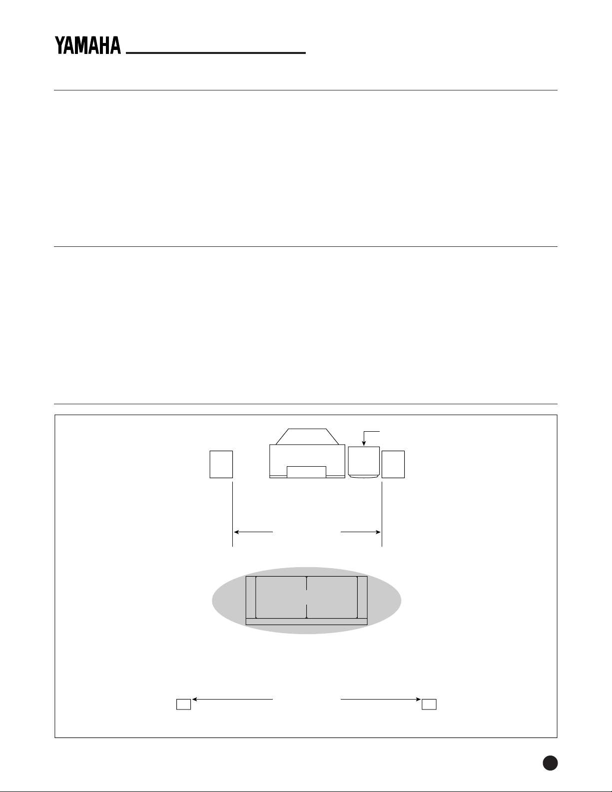
Study the speaker system plan (below), and then use
the interconnect diagrams (on the following pages) to
connect the receiver and speakers to your system.
TOOLS AND PARTS
The YHT-21 Home Theater package consists of (1) R-V703
A/V receiver with (1) RAV141 remote control, (2) 2-way
NS-A427 front-channel speakers and 16' of speaker wire,
(1) NS-AP101 package containing (1) NS-AC2A 2-way
center-channel speaker and (2) NS-A76A surround
speakers with brackets and 72' of speaker wire, (1) YSTSW40 Powered Subwoofer, and related owner’s manuals.
You will also need:
YHT-21 QUICK-CONNECT GUIDE
For the video portion, you will need a hi-fi stereo VCR or
laser disc player and a television or monitor. Refer to the
Yamaha R-V703 Owner’s Manual, as well as those that
came with your other components, for complete instructions and cautions. Be sure to turn off all power while
making connections.
Save this Quick-Connect Guide for future reference.
NOTE: Label the end of each speaker wire (i.e., left rear, right
front, etc.) before connecting them to the A/V receiver. For wire
runs over 30 feet, use larger 18- or 16-gauge speaker wire.
• Velcro (for secure fastening of NS-AC2A on TV)
• Toggle bolts, molly anchor screws, or sheet metal
screws (for securing NS-A76A speakers to walls)
NOTE: If you are unsure of how to securely and safely fasten
speakers to a wall, please contact a reliable source about the best
type of hanger for your particular wall's construction. Secure
installation is the purchaser's responsibility.
• Wire strippers (optional)
SPEAKER SYSTEM PLAN
NS-A427
(left side, same height as TV)
L = Left Channel
R = Right Channel
C = Center Channel
S = Surround Channel
YST-SW40 Subwoofer (on floor)
C
L
NS-AC2A
(on top or below TV)
Sub
NS-A427
(right side, same height as TV)
R
6'~8' apart
Couch
Listening Area
NS-A76A
(on stand or wall, at least
ear level or preferably higher)
S
8'~10' apart
S
NS-A76A
(on stand or wall, at least
ear level or preferably higher)
1
Page 4
CONNECTING AUDIO COMPONENTS
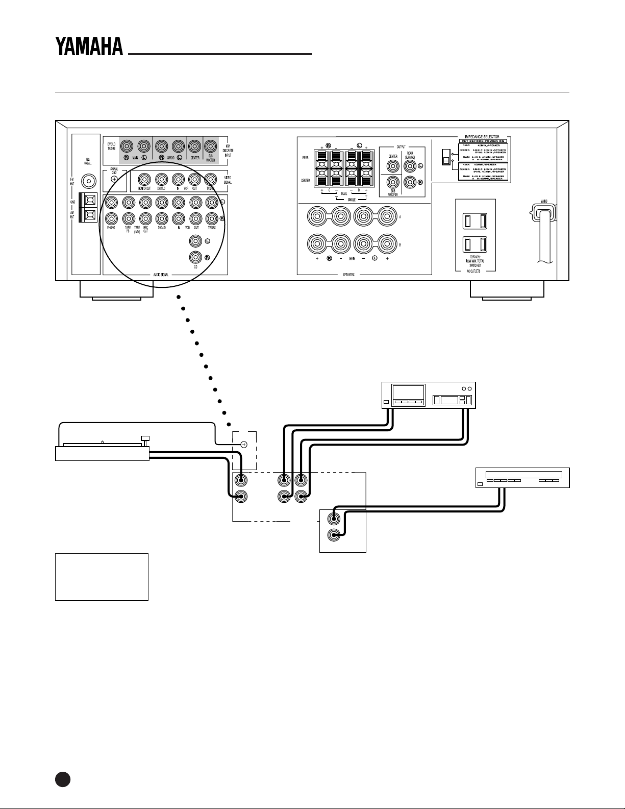
Yamaha R-V703 Receiver (Rear Panel)
YHT-21QUICK-CONNECT GUIDE
NOTE: For your convenience, the Yamaha R-V703 receiver is equipped with two
switched AC outlets (100 W max.). If desired, use them to power on connected
components (e.g., CD player or turntable) each time the receiver is turned on.
However, do not use them for components equipped with clocks (e.g., VCR).
Turntable
RCA Cable Color Codes
Yellow = Video
White = Left Audio
Red = Right Audio
Ground
L Out
R Out
GND
L
RLR
PHONO TAPE
TAPEPBREC
( MD )
AUDIO SIGNAL
OUT
Cassette Deck
* Use Playback Or Line Out
** Use Line In
L Out* R Out*
L In** R In**
CD Player (Changer)
L Out R Out
L
R
CD
Use RCA Audio Cables For Audio Interconnections
2
Page 5
CONNECTING THE YHT-21 SPEAKERS
YHT-21 QUICK-CONNECT GUIDE
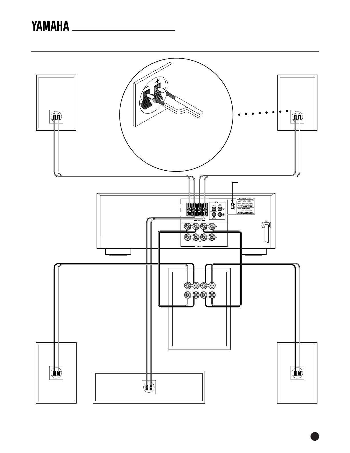
NS-A76A
(Surround Right)
Wire
Clear
Wire
Clear/
Stripe
Yamaha R-V703
A/V Receiver
(Rear Panel
Speaker Terminals)
Speaker
Wiring
RED TERMINAL = (+)
❸
❶
❷
BLK TERMINAL = (–)
❶ Strip
1
⁄4" off ends of speaker wires
❷ Push and hold down levers
❸ Insert speaker wires and
release levers
RL
Rear
Center
NS-A76A
(Surround Left)
Wire
Clear
Wire
Clear/
Stripe
Set IMPEDANCE Selector
to top position
++−
Blk
Wire
Red
Wire
Clear/
Stripe
Wire
Clear
Wire
++−−
R
L
To Speakers
+−− +
+−− +
From Amplifier
LR
LR
YST-SW40
(Subwoofer)
Blk
Wire
Red
Wire
NS-A427
(Front Right Ch.)
NS-AC2A
(Center Channel)
NS-A427
(Front Left Ch.)
3
Page 6
YHT-21QUICK-CONNECT GUIDE
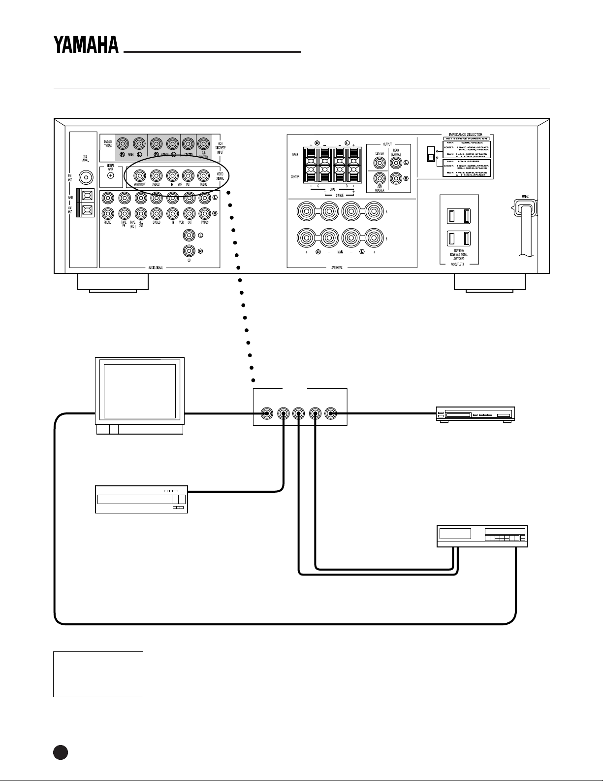
CONNECTING VIDEO CABLES FOR VIDEO COMPONENTS
Yamaha R-V703 Receiver Rear Panel
NOTE: When using a hi-fi stereo VCR, set the Tuner/Line switch (on the VCR) to Line
position to record from another source connected to the Yamaha R-V703 receiver.
Monitor/TV
DVD or LD Player (or
Video Game Player)
Video InANT In
Video Out
VIDEO SIGNAL
MONITOR
DVD/LD TV/DBSIN OUTVCR
OUT
Video Out
Use RCA Video Cables And Jacks For Video Interconnections
Optional 75-ohm Coaxial Cable
Satellite Receiver
Video In Video Out
VCR
ANT Out
(RF Out)
RCA Cable Color Codes
Yellow = Video
White = Left Audio
Red = Right Audio
4
Page 7
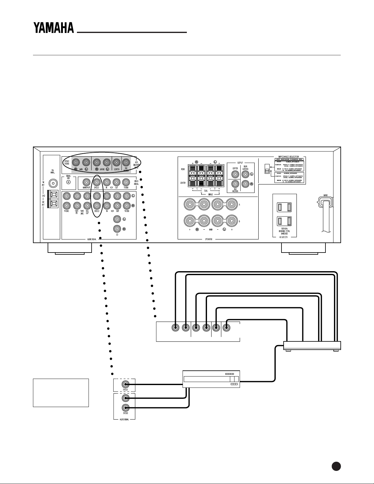
CONNECTING A 5.1-CHANNEL DECODER
If you own a 5.1-channel decoder (or a unit which
incorporates a 5.1-channel decoder), you can connect
its discrete outputs to the R-V703 as shown below.
YHT-21 QUICK-CONNECT GUIDE
record programs from a source (e.g., laserdisc
player), connect the source unit to the DVD/LD (or
TV/DBS) AUDIO SIGNAL input terminals.
• To hear playback of a stereo or mono audio source
or one encoded with Dolby Pro Logic Surround*,
connect the unit (e.g., DVD player) to the DVD/LD
(or TV/DBS) AUDIO SIGNAL input terminals.
• The discrete signals feeding to the R-V703 cannot be
recorded by a tape deck, MD recorder, or VCR. To
Yamaha R-V703 Receiver Rear Panel
• If your audio system does not include a subwoofer
(i.e., SUBWOOFER input terminals are not used), set
signal routing on the 5.1-Channel Decoder so that
the LFE channel feeds both LEFT and RIGHT MAIN
output terminals. For details, refer to the owner's
manual for your 5.1-Channel Decoder unit.
RCA Cable Color Codes
Yellow = Video
White = Left Audio
Red = Right Audio
DVD/LD
V
L
R
DVD/LD
TV/DBS
R
LR LC
MAIN
SUR
SUB
6CH
DISCRETE
INPUT
Sub Out
DVD Player
Video Out
Audio L Out Audio R Out
Use an RCA Video Cable And Jacks For Video Interconnections
Digital Audio Cable
(Optical or Coaxial)
R Main Out
L Main Out
R Sur Out
L Sur Out
Center Out
5.1-Channel Decoder
*Dolby Pro Logic Surround is a trademark of Dolby Laboratories Licensing Corp.
5
Page 8
YHT-21QUICK-CONNECT GUIDE
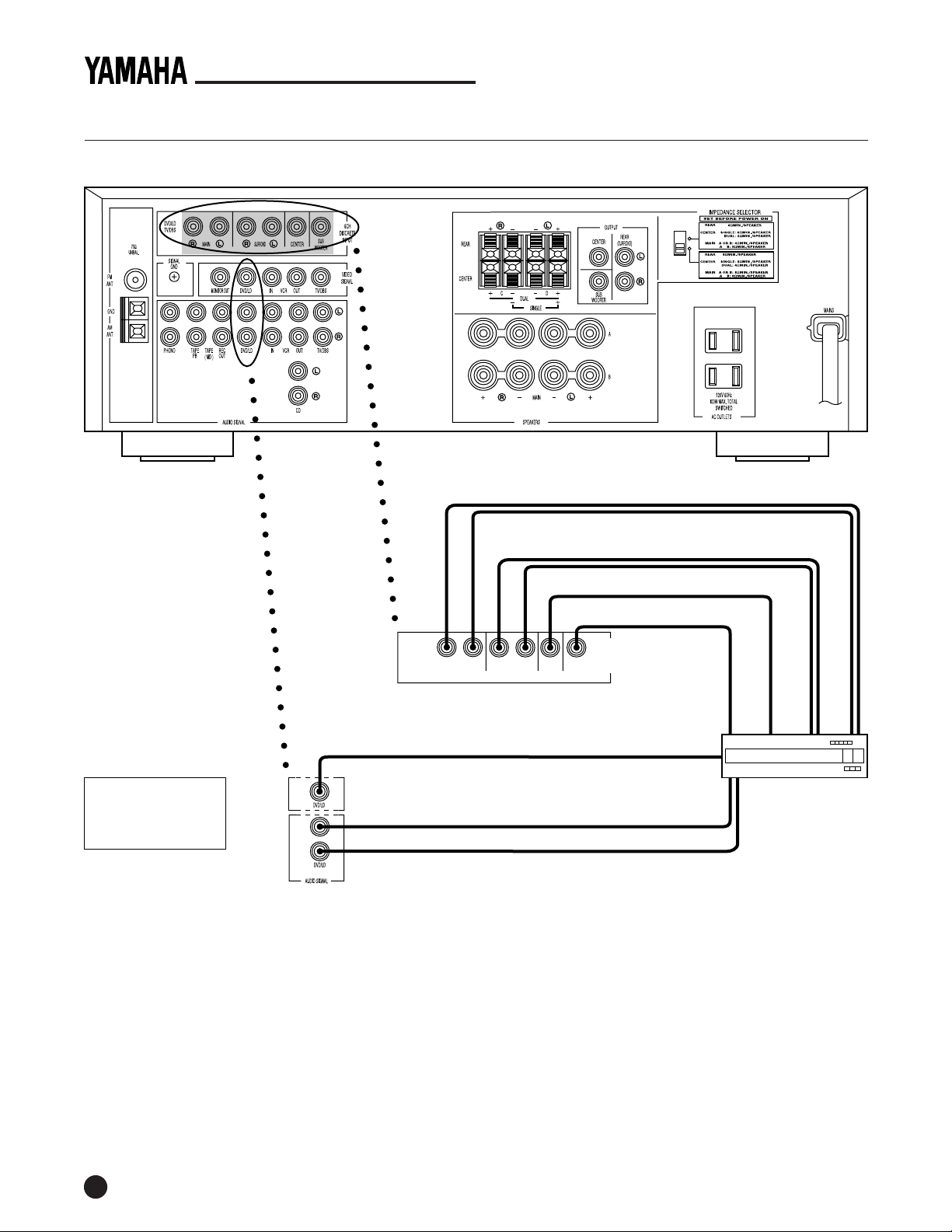
CONNECTING A DVD PLAYER WITH BUILT-IN DOLBY DIGITAL (AC-3)* DECODER
Yamaha R-V703 Receiver Rear Panel
R Main Out
L Main Out
R Sur Out
RCA Cable Color Codes
Yellow = Video
White = Left Audio
Red = Right Audio
V
L
R
DVD/LD
DVD/LD
TV/DBS
R
LR LC
MAIN
SUR
SUB
6CH
DISCRETE
INPUT
Sub Out
Video Out
Mixed Audio L Out
Mixed Audio R Out
Use an RCA Video Cable And Jacks For Video Interconnections
L Sur Out
Center Out
DVD Player
*Dolby Digital and AC-3 are trademarks of Dolby Laboratories Licensing Corp.
6
Page 9
YHT-21 QUICK-CONNECT GUIDE
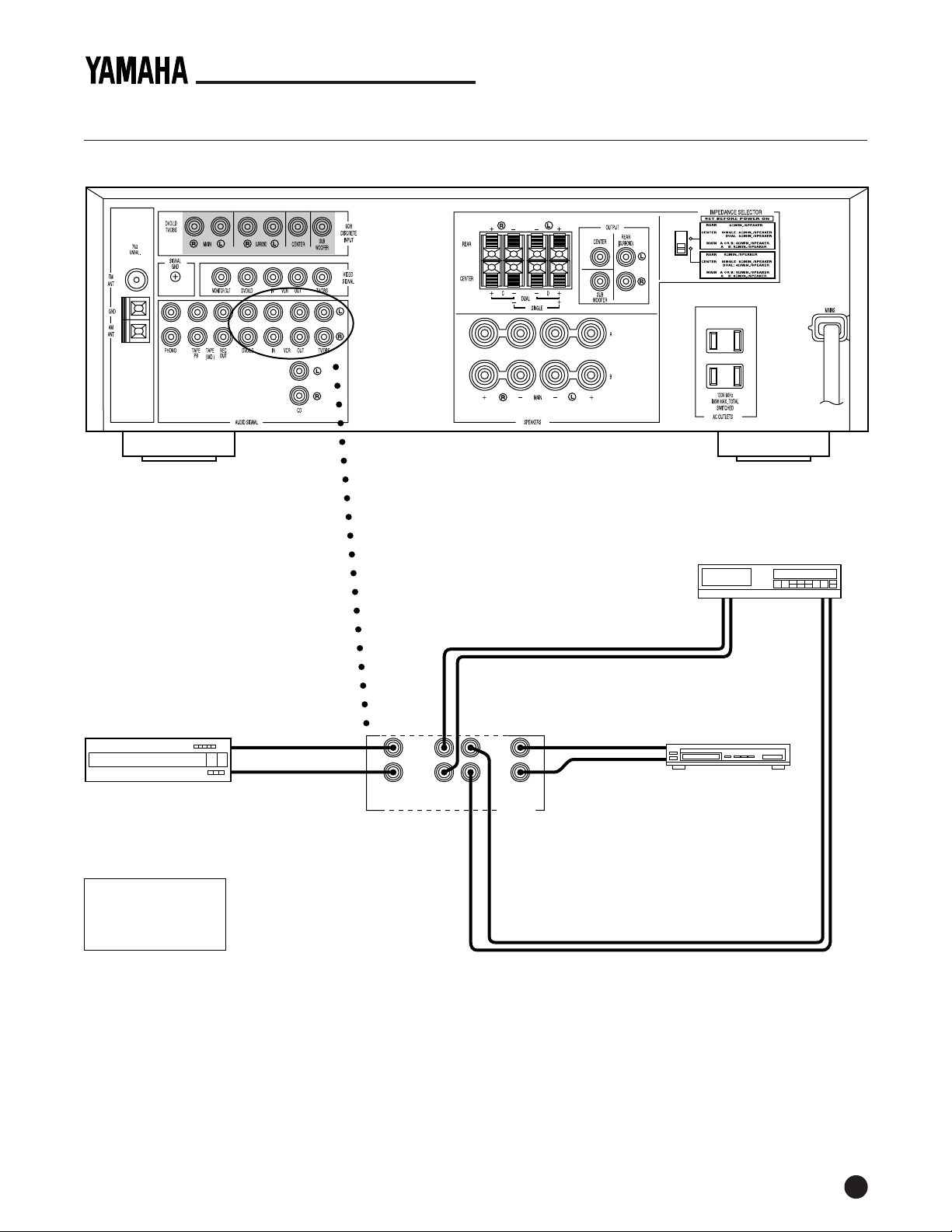
CONNECTING AUDIO CABLES FOR VIDEO COMPONENTS
Yamaha R-V703 Receiver (Rear Panel)
NOTE: When using a hi-fi stereo VCR, set the Tuner/Line switch (on the VCR) to Line
position to record from another source connected to the Yamaha R-V703 receiver.
DVD or LD Player (or
Video Game Player)
RCA Cable Color Codes
Yellow = Video
White = Left Audio
Red = Right Audio
Audio L Out
Audio R Out
L
R
DVD/LD TV/DBSVCRIN OUT
VCR
Audio
L Out
L
R
AUDIO SIGNAL
Use RCA Audio Cables And Jacks For Audio Interconnections
Audio L Out
Audio R Out
Satellite Receiver
Audio
R Out
Audio
L In
Audio
R In
7
Page 10
YHT-21QUICK-CONNECT GUIDE
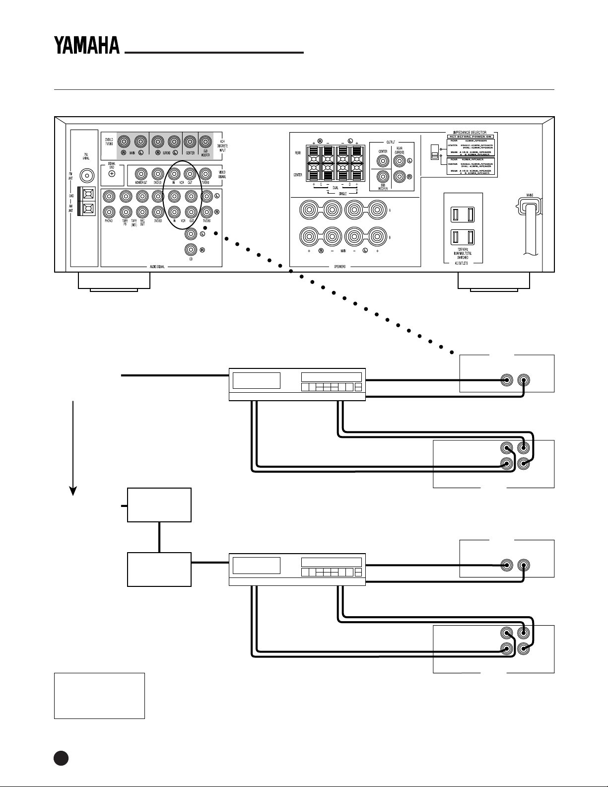
CABLE HOOK-UP (BASIC AND PREMIUM CHANNELS)
Yamaha R-V703 Receiver (Rear Panel)
NOTE: When using a hi-fi stereo VCR, set the Tuner/Line switch (on the VCR) to Line
position to record from another source connected to the Yamaha R-V703 receiver.
Basic Cable
(From Wall Jack)
OR
Premium Cable
(From Wall Jack)
RCA Cable Color Codes
Yellow = Video
White = Left Audio
Red = Right Audio
Descrambler
Converter
Box
(Channel 3 or 4
Output)
ANT In
ANT In
VCR
Audio
L Out
Audio
R Out
VCR
(Tuner set to Channel 3 or 4)
Audio
L Out
Audio
R Out
Video Out
Video In
Audio
L In
Audio
R In
RCA Audio Cables
Video Out
Video In
Audio
L In
Audio
R In
RCA Audio Cables
VIDEO SIGNAL
IN OUTVCR
RCA Video Cables
AUDIO SIGNAL
VCRIN OUT
VIDEO SIGNAL
IN OUTVCR
RCA Video Cables
AUDIO SIGNAL
VCRIN OUT
L
R
L
R
8
Page 11
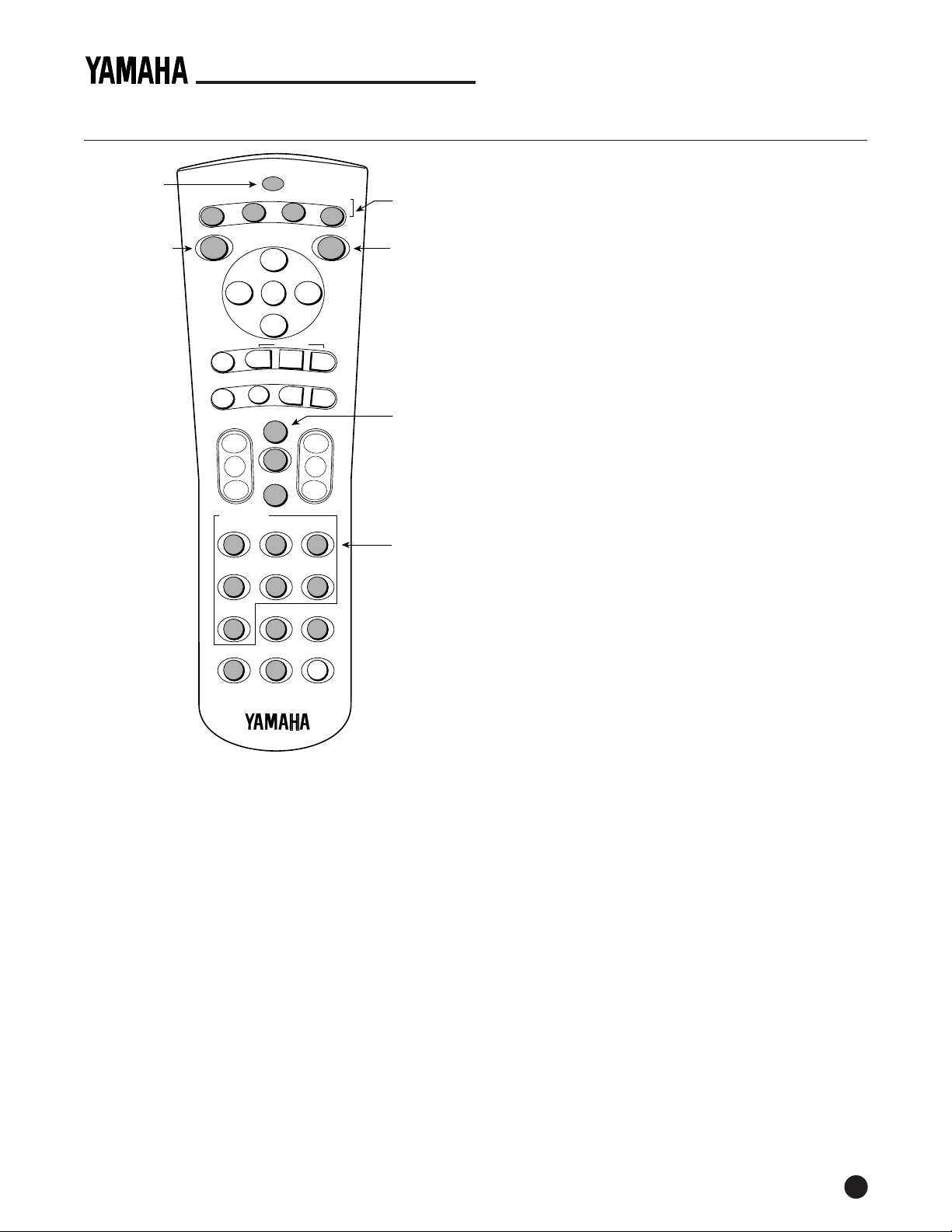
PROGRAMMING THE REMOTE CONTROL (RAV141)
Indicator LED
For Code Setup
CD
DVD
LD
SET
+
—
UP
D
INPUT
EFFECT
ON/OFF
ISC SKIP
PRESET
PLAY
PRG+
TIME/
DLY/CNT/REAR
LEVEL–
REW
PAUSE FF
LEFT RIGHTMENU
STOP
PRG–
DOWN
—
TV
DIR A
REC/
PAUSE
CH
INPUT SELECT
CD TAPE TUNER
1 2 3
PHONO
DVD/LD VCR
4 5 6
TV/DBS
7 8
UP
VCR
CBL/
DSS
TV
TAPE
SKIP/CHAPTER
DECK A/B
A/B/C/D/E
+100
SLEEP
TIME/
LEVEL+
MUTE
VOL
9
RECEIVER
POWER
DIR B
TV
TUN
Components
(Devices)
Turns On
Component’s
Power
+
Components
(Devices)
Use Keypad
To Enter
Setup Codes
YHT-21 QUICK-CONNECT GUIDE
OWER ON
P
1. Load the supplied batteries into the remote control.
2. Aim the unit at the receiver, press RECEIVER/TUN,
and then press POWER.
3. The receiver should turn on.
SETTING UP YOUR TV
1. Look up a setup code for your television set (on
pages 35 and 36 of the R-V703 Owner’s Manual).
2. Turn on the television set.
3. On the remote control, press TV; then press and
hold SETUP until the indicator LED flashes twice.
4. Using the keypad, enter the three-digit number.
The indicator LED will flash twice after your entry.
5. The TV’s controls are now assigned to the remote
control buttons (see Quick Reference Card for use).
To test the code, press TV and then POWER. If the
TV does not respond, try an alternate code.
SETTING UP YOUR CABLE BOX (OR DSS)
1. Look up a setup code for your cable box or digital
satellite system (see page 33 through 35 of the R-V703
Owner’s Manual).
ENT DISP
0
TEST
RAV141
VZ44810
The YHT-21 Home Theater package includes the
RAV141 Remote Control. It comes pre-programmed
with factory codes to control your R-V703 receiver
and most Yamaha audio components. To program
other brands of components (i.e., TV, VCR, etc.) or if
your Yamaha unit does not respond, you will need to
program the remote control with the manufacturer’s
codes (listed on pages 33 through 36 of the R-V703
Owner’s Manual).
NOTE: The RAV141 is designed to control most major
brands of audio and video components. For other units, use
the original remote control supplied with the product.
Perform the procedure for each component you own.
At the end of step 5, the remote control’s processor will
automatically assign the selected component’s control
functions to its own buttons, ready for your use.
NOTE: To clear the RAV141’s memory and return it to
the factory codes, press and hold SETUP; then enter 9 8 1.
2. Turn on the cable box (or DSS).
3. On the remote control, press CBL/DSS; then press and
hold SETUP until the indicator LED flashes twice.
4. Using the keypad, enter the three-digit number.
The indicator LED will flash twice after your entry.
5. The unit’s controls are now assigned to the remote
control buttons (see Quick Reference Card for use).
To test the code, press CBL/DSS and then POWER.
If the unit does not respond, try an alternate code.
SETTING UP YOUR VCR
1. Look up a setup code for your VCR (on page 36 of
the R-V703 Owner’s Manual).
2. Turn on the VCR.
3. On the remote control, press VCR; then press and
hold SETUP until the indicator LED flashes twice.
4. Using the keypad, enter the three-digit number.
The indicator LED will flash twice after your entry.
5. The VCR’s controls are now assigned to the remote
control buttons (see Quick Reference Card for use).
To test the code, press VCR and then POWER. If the
unit does not respond, try an alternate code.
continued on the next page...
9
Page 12
PROGRAMMING THE REMOTE CONTROL (CONT’D)
YHT-21QUICK-CONNECT GUIDE
S
ETTING UP YOUR DVD (OR LD) PLAYER
1. Look up a setup code for your DVD or LD player
(on page 34 of the R-V703 Owner’s Manual).
2. Turn on the DVD (or LD) player.
3. On the remote control, press DVD/LD; then press and
hold SETUP until the indicator LED flashes twice.
4. Using the keypad, enter the three-digit number.
The indicator LED will flash twice after your entry.
5. The unit’s controls are now assigned to the remote
control buttons (see Quick Reference Card for use).
To test the code, press DVD/LD and then POWER.
If the unit does not respond, try an alternate code.
OPERATING THE REMOTE CONTROL (RAV141)
The RAV141 Remote Control will control up to seven
different types of components (including the R-V703
receiver), each of which becomes active when you press
a selection (e.g., TV, VCR, etc.). We can only briefly
describe some functions here, and we encourage you
use the Quick Reference Card and R-V703 Owner’s Manual
to gain additional experience with this powerful unit.
PLAYING A VIDEOCASSETTE
1. Aim the remote control at the receiver, press the
blue RECEIVER/TUN button, and then press
POWER to turn it on. Press VCR (or 6) in the Input
Select area.
2. Aim the remote control at the TV, press the blue TV
button, and then press POWER to turn it on. Press
TV INPUT to select the correct input.
3. Aim the remote control at the VCR, press the blue
VCR button, and then press POWER to turn it on.
Put a tape in the VCR, press PLAY.
NOTE: At this point, the VCR controls are assigned to
the remote control, since VCR was the last blue device
button pressed. If you now press the VOLUME + (or –)
buttons, the TV/VCR volume will be raised (or lowered).
To adjust the receiver’s volume, you must press the blue
RECEIVER/TUN button to activate its functions.
SETTING UP OTHER COMPONENTS (DEVICES)
1. Look up a setup code for your component (on pages
33 through 36 of the R-V703 Owner’s Manual).
2. Turn on the component.
3. On the remote control, press the appropriate
component button; then press and hold SETUP until
the indicator LED flashes twice.
4. Using the keypad, enter the three-digit number.
The indicator LED will flash twice after your entry.
5. The unit’s controls are now assigned to the remote
control buttons (see Quick Reference Card for use).
To test the code, press the appropriate component
button and then POWER. If the unit does not
respond, try an alternate code.
PLAYING A DVD
1. Aim the remote control at the receiver, press the blue
RECEIVER/TUN button, and then press POWER to
turn it on. Press DVD/LD (or 5) in the Input Select area.
2. Press the power switch on the DVD player to turn
the unit on.
NOTE: If the DVD player is plugged into the switched AC
outlet (on the back of the receiver) and its power switch
was already engaged, the unit will come on each time the
receiver is powered on.
3. Load a DVD into the DVD player.
4. Aim the remote control at the DVD player, press the
blue DVD button, and then press PLAY.
NOTE: The DVD player’s controls are now assigned to
the remote control buttons, since DVD was the last blue
device button pressed.
5. Press the TV/DBS or DVD/LD button to switch the
R-V703 inputs from the 2-channel stereo mode to
the 6-channel discrete mode. This will accept signals
from the unit connected to the 6CH DISCRETE
INPUT terminals. Press the button again to return
the R-V703 inputs to the 2-channel mode.
10
©1998 YAMAHA ELECTRONICS CORPORATION, USA
6660 Orangethorpe Avenue, Buena Park, CA 90620
PH: (714) 522-9105; FAX: (800) 782-8484
http://www.yamaha.com
 Loading...