

Page 1
Page 2

Page 3

FOREWORD
This Supplementary Service Manual has been prepared to introduce new service and data for the
XVS650A 2004. For complete service information procedures it is necessary to use this Supplementary Service Manual together with the following manual.
XVS650 ’97 SERVICE MANUAL: 4VR-AE1
XVS650A ’98 SUPPLEMENTARY SERVICE MANUAL: 5BN4-AE1
XVS650A 2001 SUPPLEMENTARY SERVICE MANUAL: 5BN4-AE2
XVS650A 2004
SUPPLEMENTARY
SERVICE MANUAL
E2003 by Yamaha Motor Co., Ltd.
First Edition, October 2003
All rights reserved.
Any reproduction or unauthorized use
without the written permission of
Yamaha Motor Co., Ltd.
is expressly prohibited.
Page 4
EAS00002
NOTICE
This manual was produced by the Yamaha Motor Company, Ltd. primarily for use by Yamaha dealers
and their qualified mechanics. It is not possible to include all the knowledge of a mechanic in one manual. Therefore, anyone who uses this book to perform maintenance and repairs on Yamaha vehicles
should have a basic understanding of mechanics and the techniques to repair these types of vehicles.
Repair and maintenance work attempted by anyone without this knowledge is likely to render the vehicle unsafe and unfit for use.
Yamaha Motor Company, Ltd. is continually striving to improve all its models. Modifications and significant changes in specifications or procedures will be forwarded to all authorized Yamaha dealers and
will appear in future editions of this manual where applicable.
NOTE:
Designs and specifications are subject to change without notice.
EAS00004
IMPORTANT INFORMATION
Particularly important information is distinguished in this manual by the following.
The Safety Alert Symbol means ATTENTION! BECOME ALERT! YOUR
SAFETY IS INVOLVED!
WARNING
CAUTION:
NOTE: A NOTE provides key information to make procedures easier or clearer.
Failure to follow WARNING instructions could result in severe injury or death
the motorcycle operator, a bystander or a person checking or repairing the motorcycle.
A CAUTION indicates special precautions that must be taken to avoid damage
to the motorcycle.
to
Page 5
EB002000
HOW TO USE THIS MANUAL
MANUAL ORGANIZATION
This manual consists of chapters for the main categories of subjects. (See “Illustrated symbols”)
1st title
2nd title
3rd title
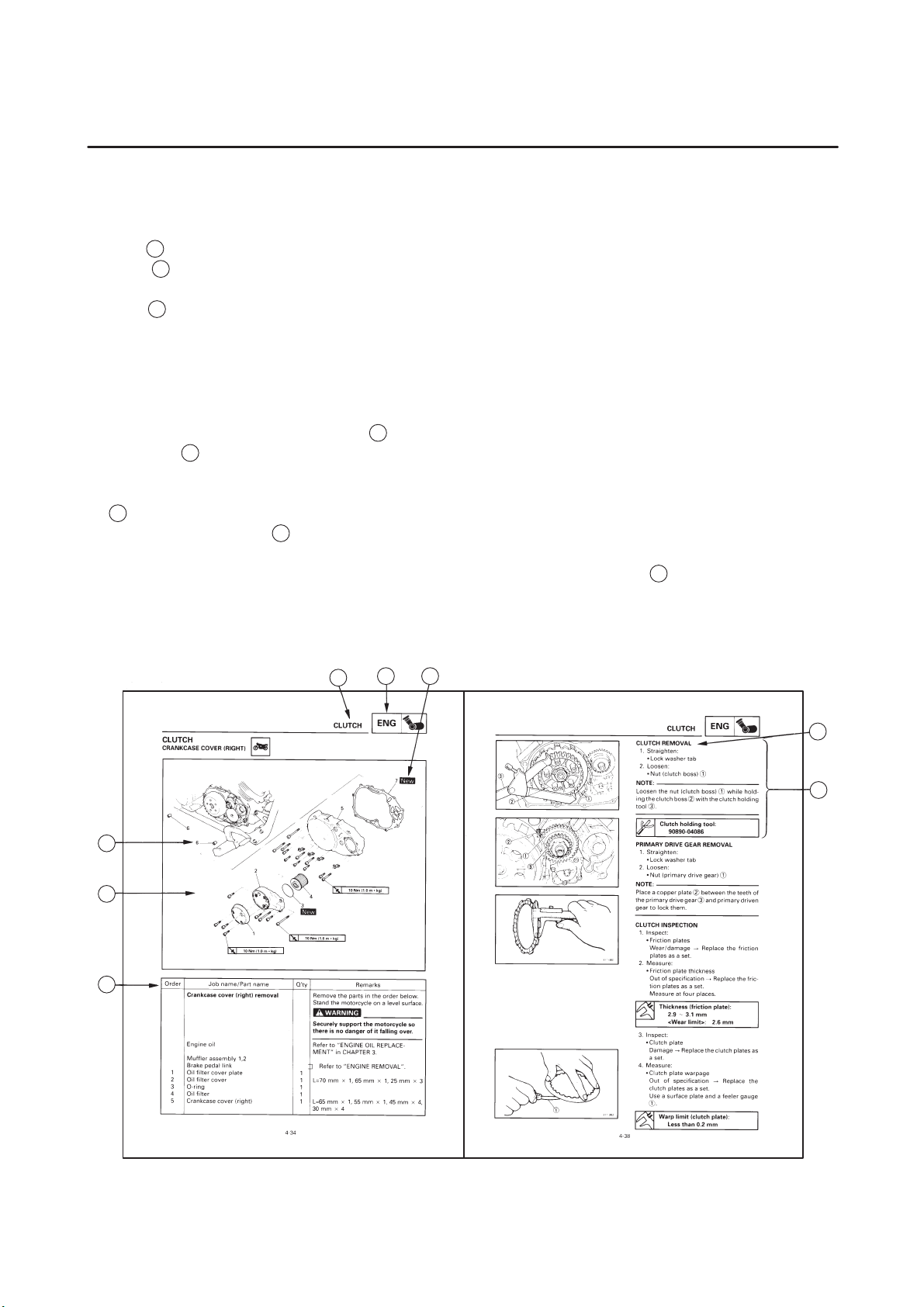
EXPLODED DIAGRAMS
To help identify parts and clarify procedure steps, there are exploded diagrams at the start of each removal and disassembly section.
1. An easy-to-see exploded diagram
2. Numbers
3. An explanation of jobs and notes is presented in an easy-to-read way by the use of symbol marks
4. A job instruction chart
5. For jobs requiring more information, the step-by-step format supplements
1
: This is the title of the chapter with its symbol in the upper right comer of each page.
2
: This title indicates the section of the chapter and only appears on the first page of each
section. It is located in the upper left comer of the page.
3
: This title indicates a sub-section that is followed by step-by-step procedures accompa-
nied by corresponding illustrations.
4
is provided for removal and disassembly jobs.
5
are given in the order of the jobs in the exploded diagram. A number that is enclosed by
a circle indicates a disassembly step.
6
. The meanings of the symbol marks are given on the next page.
7
accompanies the exploded diagram, providing the order of jobs, names of
parts, notes in jobs, etc.
the exploded diagram and the job instruction chart.
8
are given in addition to
1
2
5
4
7
6
3
8
Page 6
EAS0009
1
2
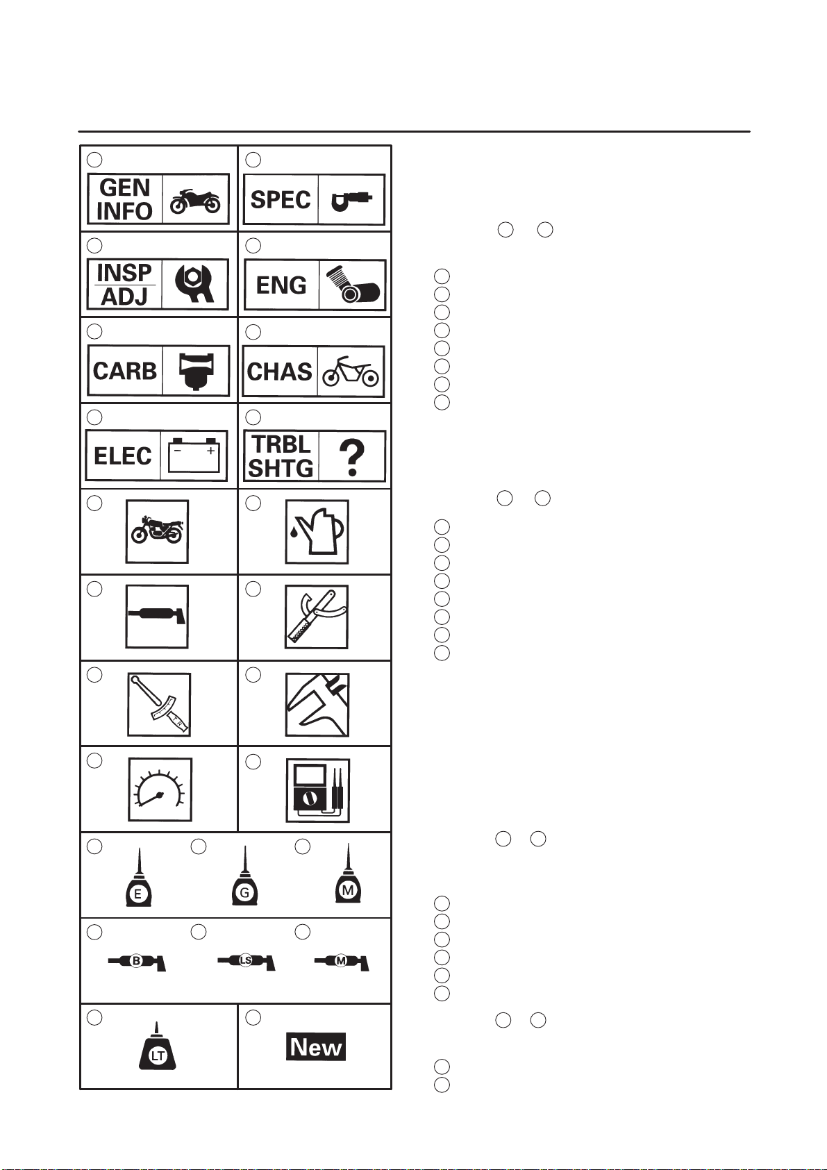
SYMBOLS
The following symbols are not relevant to every
vehicle.
Symbols
3
5
7
4
6
chapter.
General information
1
Specifications
2
Periodic inspections and adjustments
3
Engine
4
Carburation
5
Chassis
6
Electrical
7
Troubleshooting
8
8
1
to 8 indicate the subject of each
11
13
15
17
9
18 19
10
12
14
16
Symbols 9 to 16 indicate the following.
Serviceable with engine mounted
9
10
Filling fluid
11
Lubricant
12
Special tool
13
Tightening torque
14
Wear limit, clearance
15
Engine speed
16
Electrical data
Symbols 17 to 22 in the exploded diagrams indicate the types of lubricants and lubrication
points.
20
23 24
21 22
17
Engine oil
18
Gear oil
19
Molybdenum disulfide oil
20
Wheel bearing grease
21
Lithium soap base grease
22
Molybdenum disulfide grease
Symbols 23 to 24 in the exploded diagrams indicate the following:
23
Apply locking agent (LOCTITE)
24
Replace the part
Page 7

CONTENTS
SPECIFICATIONS
GENERAL SPECIFICATIONS 1. . . . . . . . . . . . . . . . . . . . . . . . . . . . . . . . . .
ENGINE SPECIFICATIONS 1. . . . . . . . . . . . . . . . . . . . . . . . . . . . . . . . . . . .
CHASSIS SPECIFICATIONS 2. . . . . . . . . . . . . . . . . . . . . . . . . . . . . . . . . . .
ELECTRICAL SPECIFICATIONS 3. . . . . . . . . . . . . . . . . . . . . . . . . . . . . . .
CABLE ROUTING 4. . . . . . . . . . . . . . . . . . . . . . . . . . . . . . . . . . . . . . . . . . . .
PERIODIC INSPECTIONS AND ADJUSTMENTS
INTRODUCTION 18. . . . . . . . . . . . . . . . . . . . . . . . . . . . . . . . . . . . . . . . . . . . . .
PERIODIC MAINTENANCE / LUBRICATION INTERVALS 18. . . . . . . . . .
ENGINE
ENGINE REMOVAL 20. . . . . . . . . . . . . . . . . . . . . . . . . . . . . . . . . . . . . . . . . . .
SIDESTAND AND CRANKCASE COVER (LEFT) 20. . . . . . . . . . . . . .
CARBURETION
CARBURETOR 21. . . . . . . . . . . . . . . . . . . . . . . . . . . . . . . . . . . . . . . . . . . . . . .
ELECTRICAL
SWITCH INSPECTION 24. . . . . . . . . . . . . . . . . . . . . . . . . . . . . . . . . . . . . . . .
SWITCH CONTINUITY INSPECTION 24. . . . . . . . . . . . . . . . . . . . . . . .
CHECKING THE LED 26. . . . . . . . . . . . . . . . . . . . . . . . . . . . . . . . . . . . . .
IMMOBILIZER SYSTEM 27. . . . . . . . . . . . . . . . . . . . . . . . . . . . . . . . . . . . . . .
SYSTEM DIAGRAM 27. . . . . . . . . . . . . . . . . . . . . . . . . . . . . . . . . . . . . . . .
CIRCUIT DIAGRAM 28. . . . . . . . . . . . . . . . . . . . . . . . . . . . . . . . . . . . . . . .
GENERAL INFORMATION 29. . . . . . . . . . . . . . . . . . . . . . . . . . . . . . . . . .
KEY ID REGISTRATION METHOD 30. . . . . . . . . . . . . . . . . . . . . . . . . . .
SELF-DIAGNOSIS ERROR CODE INDICATION 32. . . . . . . . . . . . . . .
TROUBLESHOOTING 33. . . . . . . . . . . . . . . . . . . . . . . . . . . . . . . . . . . . . .
CHECKING THE IMMOBILIZER SYSTEM 34. . . . . . . . . . . . . . . . . . . .
REPLACEMENT PARTS ON TROUBLES 36. . . . . . . . . . . . . . . . . . . . .
XVS650A 2004 WIRING DIAGRAM
Page 8

Page 9
GENERAL SPECIFICATIONS/ENGINE SPECIFICATIONS
SPECIFICATIONS
GENERAL SPECIFICATIONS
Item Standard Limit
SPEC
Model code 5SCE/5SCK
Dimensions
Overall length
Overall width
Overall height
Seat height
Wheelbase
Minimum ground clearance
Minimum turning radius
Weight
Wet (with oil and a full fuel tank)
Maximum load (except motorcycle)
2,450 mm (96.5 in)
930 mm (36.6 in)
1,105 mm (43.5 in)
710 mm (28.0 in)
1,625 mm (64.0 in)
140 mm (5.5 in)
3,500 mm (137.8 in)
249 kg (549 lb)
198 kg (437 lb)
ENGINE SPECIFICATIONS
Item Standard Limit
Carburetor
I.D. mark
Main jet (M.J)
Main air jet (M.A.J)
Jet needle (J.N)
Needle jet (N.J)
Pilot air jet (P.A.J.1)
Pilot outlet (P.O)
Pilot jet (P.J)
Bypass 1 (B.P.1)
Bypass 2 (B.P.2)
Bypass 3 (B.P.3)
Pilot screw (P.S)
Valve seat size (V.S)
Starter jet (G.S.1)
Strater jet (G.S.2)
Throttle valve size (Th. V)
Fuel level (F.L)
Engine idle speed
Intake vacuum
Engine oil temperature
5SCE 00 (5SCE)
5SCK 10 (5SCK)
#91.3
#50
4CT5-2
O-4M
#100
0.85
#20
0.8
0.8
0.8
2-1/ 2
1.0
#17.5
0.9
#140
7.5 X 8.5 mm (0.30 X 0.33 in)
1,150 X 1,250 r/ min
29.3 kPa (0.30 kg/ cm
80 X 90 _C (176 X 194 _F)
2
, 220 mmHg)
SSS
SSS
SSS
SSS
SSS
SSS
SSS
SSS
SSS
SSS
SSS
SSS
SSS
SSS
SSS
SSS
SSS
SSS
SSS
SSS
SSS
SSS
SSS
SSS
SSS
SSS
SSS
SSS
SSS
SSS
SSS
–1–
Page 10
CHASSIS SPECIFICATIONS
Item Standard Limit
Front wheel
Wheel type
Rim
Size
Material
Wheel travel
Wheel runout
Max. radial wheel runout
Max. lateral wheel runout
Rear wheel
Wheel type
Rim
Size
Material
Wheel travel
Wheel runout
Max. radial wheel runout
Max. lateral wheel runout
CHASSIS SPECIFICATIONS
Spoke wheel
16 M/ C MT3.00
Steel
140 mm (5.51 in)
SSS
SSS
Spoke wheel
15 M/ C MT3.50
Steel
98 mm (3.86 in)
SSS
SSS
SPEC
SSS
SSS
SSS
SSS
1 mm (0.04 in)
0.5 mm (0.02 in)
SSS
SSS
SSS
SSS
1mm (0.04 in)
0.5 mm (0.02 in)
Front tire
Tire type
Size
Model (manufacturer)
Tire pressure (cold)
0 X 90 kg (0 X 198 lb)
90 X 198 kg (198 X 437 lb)
Min. tire tread depth
Rear tire
Tire type
Size
Model (manufacturer)
Tire pressure (cold)
0 X 90 kg (0 X 198 lb)
90 X 198 kg (198 X 437 lb)
Min. tire tread depth
With tube
130/ 90-16M/C 67S
G703 (BRIDGESTONE)
D404F (DUNLOP)
225 kPa (2.25 kgf/cm
225 kPa (2.25 kgf/cm
SSS
With tube
170/ 180-15M/C 77S
G702 (BRIDGESTONE)
D404G (DUNLOP)
225 kPa (2.25 kgf/cm
250 kPa (2.5 kgf/ cm
SSS
2
, 2.25 bar, 33 psi)
2
, 2.25 bar, 33 psi)
2
, 2.25 bar, 33 psi)
2
, 2.5 bar, 36 psi)
SSS
SSS
SSS
SSS
SSS
SSS
1.6 mm (0.06 in)
SSS
SSS
SSS
SSS
SSS
SSS
1.6 mm (0.06 in)
–2–
Page 11
CHASSIS SPECIFICATIONS/
ELECTRICAL SPECIFICATIONS
Item Standard Limit
Brake lever & brake pedal:
Brake lever free play (at pivot)
Brake lever free play (at lever end)
Brake pedal position
Brake pedal free play
Clutch lever free play (at pivot)
Clutch lever free play (at lever end)
1 X 2 mm (0.04 X 0.08 in)
10 X 15 mm (0.39 X 0.59 in)
108 mm (4.25 in)
20 X 30 mm (0.79 X 1.18 in)
2 X 3 mm (0.08 X 0.12 in)
5 X 10 mm (0.20 X 0.39 in)
ELECTRICAL SPECIFICATIONS
Item Standard Limit
T.C.I.
Pickup coil resistance/ color
T.C.I. unit model/ manufacturer
Headlight relay
Model (manufacture)
Coil resistance
189 X 231 Ω at 20_C (68_F)/ GrayBlack
J4T150/ MITSUBISHI (5SCE)
J4T151/ MITSUBISHI (5SCK)
ACA12115-1 (MATSUSHITA)
72 X 88 Ω at 20_C (68_F)
SPEC
SSS
SSS
SSS
SSS
SSS
SSS
SSS
SSS
SSS
SSS
SSS
Thermo switch
Model (manufacture)
Fuel pump relay
Model/ manufacturer
Circuit breaker
Type
Amperage for individual circuit
MAIN
HEADLIGHT
SIGNALS
IGNITION
PARKING LIGHT
CARBURETOR HEATER
Reserve
Reserve
Reserve
Reserve
Indicatior light
Immobilizer system indicator light
5FU (NIPPON THERMOSTAT)
UC-Z61B/ MITSUBISHI
Fuse
30 A 1
15 A 1
10 A 1
10 A 1
10 A 1
15 A 1
30 A 1
15 A 1
10 A 1
5 A 1
LED 1
SSS
SSS
SSS
SSS
SSS
SSS
SSS
SSS
SSS
SSS
SSS
SSS
SSS
SSS
–3–
Page 12
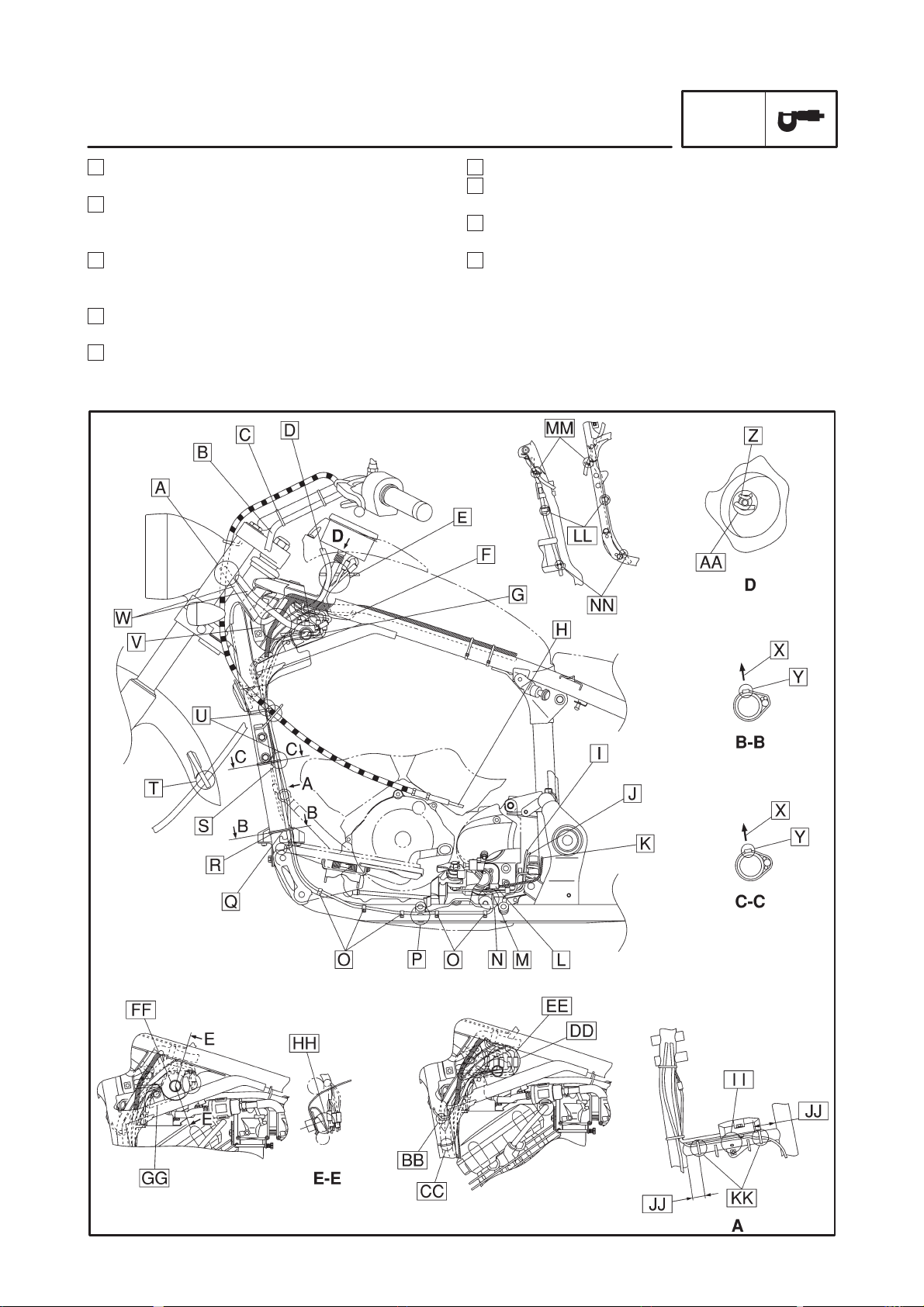
CABLE ROUTING
CABLE ROUTING
SPEC
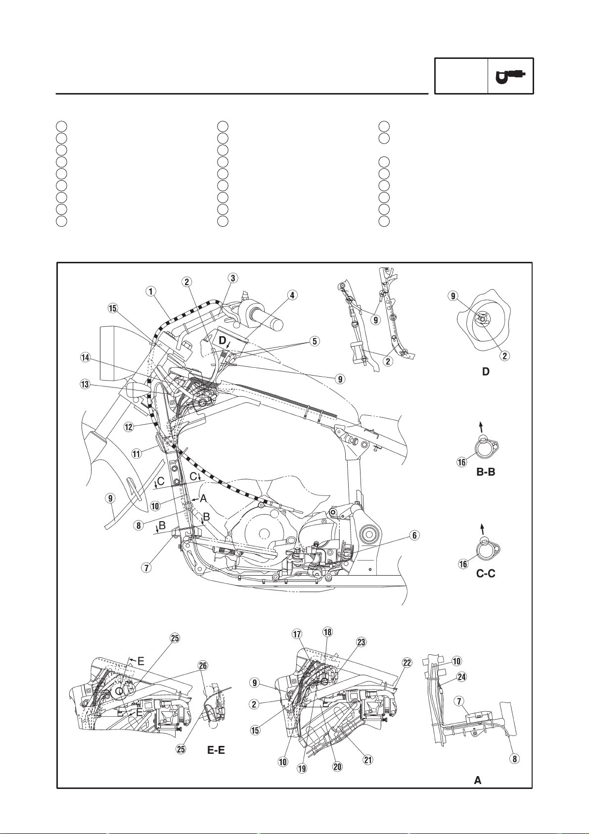
1 Clutch cable
2 Fuel tank breather hose
3 Left handlebar switch lead
4 Speedometer
5 Speedometer lead
6 Speed sensor
7 Rectifier/ regulator
8 Rear brake light switch lead
9 Speedometer cable
10 Sidestand switch lead
11 Horn
12 Head pipe cover
13 Headlight lead
14 Right handlebar switch lead
15 Vacuum chamber air vent hose
16 Frame
17 Immobilizer
18 Main switch lead
19 Immobilizer lead
20 Fuel pump and ignition coil
bracket
21 Spark plug lead
22 Fuel hose
23 Fuel pump lead
24 Rectifier/ regulator lead
25 Sheet 1
26 Flap
–4–
Page 13

CABLE ROUTING
SPEC
A Pass the front turn signal light leads (left and right)
through the hole of headlight cover from rear side.
B Pass the left handle bar switch lead through behind
the handle ber upper bracket so that there is no
slack.
C Fasten the left handlebar switch lead to the handle-
bar with a band.
D To install the fuel tank, make sure to install the fuel
tank breather hose so that it is not bent too much.
E Pass the harness and fuel breather hose to be con-
nected to the speedometer cable and speedometer
lead through the hole of fuel tank.
F Pass the harness to be connected to the speedom-
eter lead through under the wire harness.
G Rectifier / regulator lead should not be positioned
higher than the bracket.
H To the engine
I A.C. magneto lead (from the engine)
J Pickup coil lead (from the engine)
K Harness to be connected to the speed sensor (to
the wire harness)
L Push in the coupler inside of the engine lead and
crank case after the coupler is connected so that it
does not come out.
–5–
Page 14
CABLE ROUTING
SPEC
M Pass the speed sensor lead through inside of the
engine lead.
N Pass the side stand switch lead through inside of
the side stand bracket and install so that there is no
adverse slack.
O Hold the side stand switch lead with a plastic clamp.
Any direction of the plastic clamp opening can be
accepted.
P Pass the sidestand switch lead through under the
frame boss.
Q Fasten the rear brake light switch lead, sidestand
switch lead and rectifier/ regulator lead to the frame
with a band.
R Position the band immediately under the T stud.
S Position the band immediately under the frame
boss.
T Pass the speedometer cable through the holder on
the front fender.
U Fasten the rear brake light switch lead, side stand
switch lead and rectifier/ regulator lead to the frame
with a band. They should not contact with the cylinder head cover during routing.
–6–
Page 15

CABLE ROUTING
SPEC
V Position the right handle bar switch lead and head
light switch lead at the outer position of all
harnesses and leads behind the frame head pipe.
Particularly, the right handle bar switch lead should
be positioned at the outermost section.
W Do not cross the handle bar switch lead and head
light lead at the out side of the head pipe cover.
X Inside the frame
Y Position of cutting section
Z Harness to be connected to the speedometer lead
AA Pass the harness and fuel breather hose to be
connected to the speedometer cable and
speedometer lead through the hole of fuel tank.
BB Pass the speedometer cable through the holder
of the frame.
CC Pass the fuel tank beather hose and carburetor
air vent hose through the holder of the frame.
DD Allocate the couplers for all leads behind the
frame head pipe at the rear section.
EE Allocate the coupler to be connected to the rectifi-
er/ regulator lead inside of the vehicle body and
make it not to come out.
FF Pass the flap through the hole of fuel tank stay
and install. (for both right and left sides)
GG Install the sheet 1 so that the lower edge is hidden
by the frame.
–7–
Page 16

CABLE ROUTING
SPEC
HH Position the sheet 1 so that the edge of frame
does not protrude.
II Pass the rear brake light switch lead between the
frame bracket and the rectifier/ regulator.
There should be no catching and slack between
the rectifier/ regulator attaching bracket and the
rear brake light switch lead.
JJ About 30 mm (1.18 in)
KK Fasten the rear brake light switch to the frame
with a band.
LL Clamp the fuel tank breather hose to the frame
with a holder.
MM Pass the speedometer cable through the front
guide.
NN Pass the fuel tank breather hose through the
holder of the frame.
–8–
Page 17

CABLE ROUTING
SPEC
1 Fuse box
2 Battery positive lead
3 Spark plug lead
4 Vacuum chamber air vent hose
5 Starter cable
6 Right handlebar switch lead
7 Throttle cables
8 Brake hose
9 Thermo switch
10 Thermo switch lead
11 Battery cover
12 Battery
13 Turn signal relay
14 Starter relay
15 Carburetor heater
16 Headlight relay
17 Frame bracket
18 Starting circuit cut-off relay
19 Ignitor unit
20 Starter motor positive lead
21 Battery negative lead
22 Wire harness
23 Anti-theft alarm lead
24 Rear shock absorber
–9–
Page 18

CABLE ROUTING
SPEC
A Hold the battery negative lead and tail /brake light
lead with a plastic clamp on the battery cover.
B Hold the battery negative lead coupler and
tail/ brake light coupler with a plastic clamp on the
battery cover.
C Pass the harness to be connected to the tail/ brake
light lead and battery negative lead through under
the battery positive lead.
D Clamp the harness to be connected to the starter
relay and the harness to be connected to the fuse
box with a plastic clamp. Any direction of the clamp
can be accepted.
E About 30 mm (1.18 in)
F This lead is connected to the ignition coil.
G Cut section of the band should be positioned under
the handle bar so that there is no contact with the
brake hose.
H Fasten the right handlebar switch lead to the han-
dlebar with a band.
I Route the right handle bar switch lead so that there
is no slack behind the handle bar upper bracket.
J Cross the throttle cables ahead of the wire guide.
K Clamp the grommet of the brake hose at the holder.
L Pass the left handlebar switch lead through over the
main switch.
M Position the left handle bar switch lead coupler
above the immobilizer unit.
–10–
Page 19

CABLE ROUTING
SPEC
N Hold the spark plug lead to the clamp at the end of
the front side protector.
O Pass the harness to be connected to the ignition coil
through inside of the vehicle body and connect it to
the ignition coil.
P Position of cut section
Q Neutral switch lead (from the engine)
R Pickup coil lead (from the engine)
S A.C. magneto lead (from the engine)
T This lead is connected to the speed sensor.
U Battery negative lead (from the engine)
V Starter motor positive lead (from the engine)
W Pass the starter motor positive lead through outside
of the battery negative lead.
X Fasten the pick up coil lead, A.C. magneto lead,
neutral switch lead and starter motor lead to the inside of the frame side bracket with a band.
There should be no contact with the end face of the
side cover 4.
Y Fasten the battery negative lead, starter motor posi-
tive lead, headlight relay lead and starting circuit
cut-off relay lead to the frame bracket with a band.
Z Hold the harness to be connected to the starting cir-
cuit cut-off relay with the clamp on the battery cover.
AA Pass it between the frame and the battery box.
There should be no twisting and prying with the
head light relay and starting circuit cut-off relay
during routing the leads.
–11–
Page 20

CABLE ROUTING
SPEC
BB Hold the headlight relay lead with a plastic clamp.
CC Check that the starting circuit cut-off relay is se-
curely fastened to the battery box after wiring to
the wire harness.
DD Pass it between the frame side bracket and the
battery box. Mud guard should be positioned between the frame side bracket’s end face and the
lead.
EE Hold the harness to be connected to the fuse box
with the clamp on the battery box.
FF Hold the battery positive lead with the battery box
clamp above the starter relay.
GG There should be no contact between the carbure-
tor heater relay and the wire harness.
HH Fasten the headlight relay lead and starting cir-
cuit cut-off relay lead to the frame with a band.
II Fasten the wire harness and engine lead.
JJ There should be no contact between the wire har-
ness and engine lead and the rear shock absorber.
KK To the starter relay
LL To the turn signal relay
MM To the rear fender
NN To the battery negative lead
OO Pass the harness to be connected to the igniter
unit through the hole of battery box.
PP To the carburetor heater relay
–12–
Page 21

CABLE ROUTING
SPEC
QQ Hold the wire harness and engine lead with a
plastic clamp.
RR Within 10 mm (0.39 in)
SS Fasten the wire harness and engine lead to the
frame under the wire harness junction with a
band.
TT Clamp the wire harness. Make sure to insert the
clamp to the hole of frame. Securely tighten up
the clamp at the marked point of the wire harness.
UU Fasten the starter cable to the frame tank rail with
a band.
VV Inner side of the frame in the horizontal direction
of the vehicle body
WW Fasten the anti-theft alarm harness and battery
positive lead with the battery band.
XX Push in the anti-theft alarm couplers in one
bundle to the battery box. Route the wire harness
and couplers so that they are not caught by the
end face of the side cover.
YY Clamp the brake hose at the holder.
–13–
Page 22

1 Throttle cables
2 Brake hose
3 Right handlebar switch lead
4 Clutch cable
5 Left handlebar switch lead
6 Front turn signal light (left)
7 Front turn signal light (right)
8 Rectifier/ regulator lead coupler
9 Spark plug lead
10 Ignition coil
11 Silencer
12 Wire harness
13 Frame
14 Air filer case
CABLE ROUTING
SPEC
–14–
Page 23

CABLE ROUTING
SPEC
A Cross the left handlebar switch lead and right han-
dlebar switch lead ahead of the head pipe.
Pass the left handlebar switch lead through outside
of the right handlebar switch lead during routing.
B Hold the handlebar switch leads (right and left) with
a plastic clamp. Make sure to fit the clamp pawl for 4
notches.
C Pass the throttle cable from the top side of the hold-
er located under the handlebar upper bracket.
D Fuel breather hose (to the fuel tank)
E Starter cable (to the carburetor)
F Harness to be connected to the throttle position
sensor
G Pass the starter cable between the ignition coil and
the spark plug lead and route it along the concave
on the cylinder head cover.
H Solenoid valve lead (from the carburetor)
I Position the solenoid valve lead between the igni-
tion coil and the heat resistant sheet pasted on the
cylinder head cover.
J There should be nothing located under the wire har-
ness such as a coupler (of the fuel sender lead).
–15–
Page 24

CABLE ROUTING
SPEC
K Pass the neutral switch lead, pick up coil lead, A.C.
magneto lead and fuel sender lead through under
the harness to be connected to the ignition coil and
position it above the heat resistant sheet pasted on
the cylinder head cover (Position the couplers so
that they do not contact with the rear side edge section behind the ignition coil.).
L Harness to be connected to the fuel sender lead (to
the fuel tank)
M Neutral switch lead (from the engine)
N Pick up coil lead (from the engine)
O A.C. magneto lead (from the engine)
P 40 to 50 mm (1.57 to 1.97 in)
Q About 20 mm (0.79 in) from the bottom of frame’s R
R Pass the thermo switch lead through inside of the si-
lencer breather pipe and connect it to the wire harness.
S There should be no slack with the wire harness.
T Harness to be connected to the speedometer lead
U Pass a band through the gusset hole and clamp the
wire harness. Position the fastened section of the
band on the gusset. (Cut off the excessive part.)
V Frame side in the horizontal direction of the vehicle
body
W Fasten the wire harness to the tank rail wire a band.
X Position of cut section
Y Position it lower than the frame top face.
Z Set in the wire harness between the concave of the
air filter case and the frame.
–16–
Page 25

AA Harness to be connected to the speedometer
lead
BB Speedometer cable (to the fuel tank)
CC Fuel tank breather hose (to the fuel tank)
CABLE ROUTING
SPEC
–17–
Page 26

INTRODUCTION/PERIODIC MAINTENANCE/
No.ITEM
CHECKS OR MAINTENANCE JOB
g
5
Air filter element
7*Front brake
8*Rear brake
9*Brake hose
13*Swingarm
14*Steering bearings
LUBRIATION INTERVALS
EB300000
INSP
ADJ
PERIODIC INSPECTIONS AND ADJUSTMENTS
INTRODUCTION
This chapter includes all information necessary to perform recommended inspections and adjustments. These preventive maintenance procedures, if followed, will ensure more reliable vehicle operation and longer service life. The need for costly overhaul work will be greatly reduced. This information
applies to vehicles already in service as well as to new vehicles that are being prepared for sale. All
service technicians should be familiar with this entire chapter.
NOTE:
D The annual checks must be performed every year, except if a kilometer-based maintenance
is performed instead.
D From 50,000 km, repeat the maintenance intervals starting from 10,000 km.
D Items marked with an asterisk should be performed by a Yamaha dealer as they require special
tools, data and technical skills.
EB301000
PERIODIC MAINTENANCE/LUBRICATION INTERVALS
ODOMETER READING ( 1,000 km)
1 10 20 30 40
1 * Fuel line D Check fuel hoses for cracks or damage. √ √ √ √ √
2 * Fuel filter D Check condition. √ √
D Check condition.
3 Spark plugs
4 * Valves
6 Clutch
*
*
*
10 * Wheels
11 * Tires
12 * Wheel bearings D Check bearing for looseness or damage. √ √ √ √
*
*
15 * Chassis fasteners D Make sure that all nuts, bolts and screws are properly tightened. √ √ √ √ √
16 Sidestand
17 * Sidestand switch D Check operation. √ √ √ √ √ √
18 * Front fork D Check operation and for oil leakage. √ √ √ √
Shock absorber
19 *
assembly
20 * Carburetors
21 Engine oil
D Clean and regap.
D Replace. √ √
D Check valve clearance.
D Adjust.
D Clean. √ √
D Replace. √ √
D Check operation.
D Adjust.
D Check operation, fluid level and vehicle for fluid leakage. √ √ √ √ √ √
D Replace brake pads. Whenever worn to the limit
D Check operation and adjust brake pedal freeplay. √ √ √ √ √ √
D Replace brake shoes. Whenever worn to the limit
D Check for cracks or damage. √ √ √ √ √
D Replace. Every 4 years
D Check runout, spoke tightness and for damage.
D Tighten spokes if necessary.
D Check tread depth and for damage.
D Replace if necessary.
D Check air pressure.
D Correct if necessary.
D Check operation and for excessive play. √ √ √ √
D Lubricate with lithium-soap-based grease. Every 50,000 km
D Check bearing play and steering for roughness. √ √ √ √ √
D Lubricate with lithium-soap-based grease. Every 20,000 km
D Check operation.
D Lubricate.
D Check operation and shock absorber for oil leakage. √ √ √ √
D Check starter (choke) operation.
D Adjust engine idling speed and synchronization.
D Change.
D Check oil level and vehicle for oil leakage.
√ √
√ √ √ √
√ √ √ √ √
√ √ √ √
√ √ √ √
√ √ √ √ √
√ √ √ √ √ √
√ √ √ √ √ √
ANNUAL
CHECK
–18–
Page 27

PERIODIC MAINTENANCE/LUBRICATION INTERVALS
NO.ITEM
CHECKS OR MAINTENANCE JOB
23
Final gear oil
INSP
ADJ
Engine oil filter
22
element
Front and rear brake
24 *
switches
Moving parts and
25
cables
Throttle grip housing
26 *
and cable
Muffler and exhaust
27 *
pipe
Lights, signals and
28 *
switches
ODOMETER READING (x 1,000 km)
1 10 20 30 40
D Replace. √ √ √
D Check oil level and vehicle for oil leakage. √ √ √
D Change. √ √ √
D Check operation. √ √ √ √ √ √
D Lubricate. √ √ √ √ √
D Check operation and free play.
D Adjust the throttle cable free play if necessary.
D Lubricate the throttle grip housing and cable.
D Check the screw clamp for looseness. √ √ √ √ √
D Check operation.
D Adjust headlight beam.
√ √ √ √ √
√ √ √ √ √ √
ANNUAL
CHECK
NOTE:
D The air filter needs more frequent service if you are riding in unusually wet or dusty areas.
D Hydraulic brake service
S Regularly check and, if necessary, correct the brake fluid level.
S Every two years replace the internal components of the brake master cylinder and caliper, and
change the brake fluid.
S Replace the brake hoses every four years and if cracked or damaged.
–19–
Page 28

ENGINE
ENGINE REMOVAL
SIDESTAND AND CRANKCASE COVER (LEFT)
ENGINE REMOVAL
ENG
64 Nm (6.4 mSkg, 46 ftSlb)
30 Nm (3.0 mSkg, 22 ftSlb)
13 Nm (1.3 mSkg, 9.4 ftSlb)
Order Job name/ Part name Q’ty Remarks
Side stand and crankcase cover
(left) removal
Engine oil
Side cover (left)
1
Middle gear case cover
2
Middle gear case cover stay
3
Sidestand assembly
4
Shift pedal/ footrest (left)
5
Clutch cable
6
Neutral switch lead
7
Crankcase cover (left)/ gasket
8
Dowel pins
9
10
Rectifier/ regulator
10 Nm (1.0 mSkg, 7.2 ftSlb)
Remove the parts in the order below.
Drain
Refer to “ENGINE OIL REPLACEMENT”
in CHAPTER 3. (Manual No.: 4VR-AE1)
Do not remove the “:” bolts.
1
1
1
1
Refer to “SHIFT PEDAL INSTALLATION”.
1/1
(Manual No.: 4VR-AE1)
1
1
1/1
2
1
For installation, reverse the removal
procedure.
10 Nm (1.0 mSkg, 7.2 ftSlb)
–20–
Page 29

CARBURETOR
CARBURETOR
CARBURETION
CARB
Order Job name/ Part name Q’ty Remarks
1
2
3
4
5
6
7
8
9
10
11
Carburetor removal
Fuel tank
Air filter case assembly
Air duct
Cylinder head breather hose
Throttle position sensor lead coupler
Thermo switch lead coupler
Fuel cut solenoid valve lead coupler
Fuel hose
Carburetor assembly
Starter cable
Throttle cables
Cover
Remove the parts in the order below.
Refer to “FUEL TANK AND SEATS” in
CHAPTER 3. (Manual No.: 4VR-AE1)
1
1
1
Disconnect
1
1
2
1
1
NOTE:
1
2
After removing the carburetor
assembly, remove the starter cable
and throttle cables.
1
For installation, reverse the removal
procedure.
–21–
Page 30

CARBURETOR
CARB
Order Job name/ Part name Q’ty Remarks
Carburetor disassembly
Disassemble the parts in the order
below.
Carburetor heater lead
10
11
12
1
2
Carburetor heaters 1
3
Carburetor heaters 2
4
Float chamber
5
Float
6
Needle valve set
7
Main jet
8
Jet holder
9
Pilot jet
Jet needle set
Needle jet
Starter plunger set
1
2
2
1
1
1
1
1
1
1
1
1
12V 15W
12V 30W
Refer to “CARBURETOR ASSEMBLY”
in chapter 5. (Manual No.: 4VR-AE1)
–22–
Page 31

CARBURETOR
CARB
Order Job name/ Part name Q’ty Remarks
13
Diaphragm set
1
Refer to “CARBURETOR ASSEMBLY” in
chapter 5. (Manual No.: 4VR-AE1)
14
Throttle position sensor
1
Refer to “THROTTLE POSITION
SENSOR (TPS) INSPECTION AND
ADJUSTMENT” in chapter 5. (Manual
No.: 4VR-AE1)
15
Pilot screw
1
Refer to “CARBURETOR ASSEMBLY” in
chapter 5. (Manual No.: 4VR-AE1)
16
17
18
Main air jet
Washer
Fuel out solenoid
1
2
2
For assembly, reverse the disassembly
procedure.
–23–
Page 32

SWITCH INSPECTION
ELEC
ELECTRICAL
SWITCH INSPECTION
SWITCH CONTINUITY INSPECTION
Refer to “SWITCH INSPECTION” and check for continuity between lead terminals. (Manual No.: 4VR-AE1)
Poor connection, no continuity ! Correct or replace.
: The coupler locations are circled.
–24–
Page 33

SWITCH INSPECTION
ELEC
1 Pass switch
2 Dimmer switch
3 Horn switch
4 Clutch switch
5 Turn signal switch
6 Main switch
7 Front brake switch
8 Engine stop switch
9 Start switch
10 Hazard switch
11 Fuse
12 Rear brake switch
13 Sidestand switch
14 Neutral switch
–25–
Page 34

SWITCH INSPECTION
CHECKING THE LED
The following procedures applies to the LED.
1. Check:
S LED (for proper operation)
Improper operation ! Replace.
a. Disconnect the meter assembly coupler (me-
ter assembly side).
b. Connect two jumper leads
tery terminals to the coupler terminal as
shown.
Battery positive lead ! green/ blue terminal
Battery negative lead ! black terminal
ELEC
1
from the bat-
WARNING
S A wire that is used as a jumper lead must
have at least the same capacity of the battery lead, otherwise the jumper lead may
burn.
S This check is likely to produce sparks,
therefore, make sure no flammable gas or
fluid is in the vicinity.
c. When the jumper leads are connected to the
terminals the respective LED should illuminate.
Does not light ! Replace the meter assembly.
–26–
Page 35

IMMOBILIZER SYSTEM
SYSTEM DIAGRAM
IMMOBILIZER SYSTEM
ELEC
1 MAIN SWITCH AND IMMOBILIZER UNIT
2 IMMOBILIZER SYSTEM INDICATOR LIGHT
3 IGNITOR UNIT
G/L Green/Blue. . . .
Br/ L Brown/ Blue. . .
R Red. . . . . .
R/ G Red /Green. . .
R/ W Red/ White. . .
Y/ L Yellow /Blue. . . .
–27–
Page 36

CIRCUIT DIAGRAM
IMMOBILIZER SYSTEM
ELEC
–28–
3 Immobilizer unit
4 Main switch
5 Fuse (ignition)
6 Fuse (main)
9 Battery
14 Ignitor unit
24 Immobilizer system indicator light
30 Fuse (backup)
Page 37

IMMOBILIZER SYSTEM
GENERAL INFORMATION
S When the main switch is turned “ON” with the registered key, the immobilizer system indicator light
comes on for about 0.5 second and then goes off.
S To check the immobilizer system, follow the steps in the troubleshooting chart.
S To use the immobilizer key, keep it away from other keys. Otherwise, the key code signal may not work
or the correct action may be disturbed.
S The key contains the electronic component (transponder). Do not drop or hit it with a solid metal. Do
not leave it on the dashboard of vehicle where the temperature may rise.
S Do not put it in the water. (when washing clothes for example)
S Do not place it near a magnet or a loud speaker.
S If all keys are missing, the engine control unit (ignitor unit) is required to replace together with the keys
and the immobilizer unit.
S Immobilizer unit cannot be operated with the copy key until the transponder code of the code re-regis-
tering key is registered to the immobilizer unit.
S Total three key codes are registered to the immobilizer unit, which are one code re-registering key
code and two standard key codes.
S Among them, two of standard key codes can be registered to prepare for the case when the key is lost.
To register, the code re-registering key is needed.
ELEC
1. Code re-registering key (red bow)
2. Standard key (black bow)
–29–
Page 38

IMMOBILIZER SYSTEM
KEY ID REGISTRATION METHOD
Initially one code re-registering key and two standard keys have been registered with the immobilizer
system.
In the course of use, you may encounter the following case where re-registration of code re-registering/ standard key is required.
Code re-registering key registration:
When the immobilizer unit or ignitor unit, failed and the unit was replaced, the unit cannot be used until
the key ID is registered because it is not registered to the unit.
a. As usual steps, when the main switch is turned “ON”, the immobilizer system indicator light goes on
for about one second.
b. If the immobilizer system indicator light goes off, it shows that the code re-registering key registra-
tion is finished.
c. Check that the engine can be started.
d. Consequently, carry out the standard key registration, according the section below.
Standard key registration:
ELEC
When you lost a standard key and need a new one. Or when the code re-registering key is re-registered
after the immobilizer unit or the ignitor unit, are replaced.
a. Check that the immobilizer system indicator light shows the standby mode.
To initiate the standby mode, turn “OFF” the main switch and then it will be the standby mode when it
passes 30 seconds. When 24 hours passed, the standby mode ends and the immobilizer system
indicator light stops flashing.
b. After the main switch is turned “ON” with the code re-registering key, within 5 seconds, turn “OFF”
the main switch and then turn “ON” the main switch with the standard key (the first new key) that you
want to register.
c. It becomes the key registration mode and two standard key IDs that have been stored in the memory
are erased and the first new standard key ID will be registered. At this time, the indicator light quickly
blinks (“OFF” for 0.5 sec. and “ON” for 0.5 sec.).
d. In the condition as mentioned above (while the immobilizer system indicator light continues quick
flashing), after the main switch is turned “ON” with the first new standard key, turn “OFF” the main
switch within 5 seconds, and then turn “ON” the main switch with the standard key that you want to
register (which is the second new key or the standard key remained in hand).
NOTE:
Fast flashing goes off when it elapses 5 seconds and the registration mode is finished. In this case, the
second standard key cannot be registered and only the first standard key is registered.
–30–
Page 39

IMMOBILIZER SYSTEM
ELEC
e. When the registration is finished, the immobilizer system indicator light goes off.
f. Check that the engine can be started with the registered two standard keys.
When one
Code re-registering
key
First unregistered
standard key
standard key
is registered.
Flashing ends when it elapses 5 seconds and the
registration for the seconds standard key is impossible.
When two
standard keys
Code re-registering
key
First unregistered
standard key
Second unregistered
standard key.
are registered.
Flashing ends when the registration of the seconds
unregistered standard key is complete.
Important note:
If you lost a standard key, immediately re-register your code re-registering key and the remaining standard key (if any). This will delete the stored registration data, protecting the motorcycle against being
started with the lost key.
–31–
Page 40

IMMOBILIZER SYSTEM
ELEC
SELF-DIAGNOSIS ERROR CODE INDICATION
When the system failure occurred, the error code number is flashed at the immobilizer system indicator
light. The pattern of flashing also shows the error code.
Error code Detection Symptoms Trouble Measures
51 Immobilizer
unit
52 Immobilizer
unit
53 Immobilizer
unit
54 Immobilizer
unit
55 Immobilizer
unit
56 Ignitor unit Undefinition code is re-
Cannot transmit code between the key and immobilizer unit.
Codes do not match between
the key and immobilizer unit.
Cannot transmit code between the ignitor unit and immobilizer unit.
Codes do not match between
ignitor unit and immobilizer
unit.
Key code registration error. Same standard key was attempted
ceived.
1) Objects that may keep off radio
waves exist around the keys and
antennas.
2) Immobilizer unit failure.
3) Key failure.
1) Disturbed by other transponder.
Failed to verify continually for ten
times.
2) Unregistered standard key was
used.
Noise interference or disconnected
lead/ cable.
1) Obstruction due to radio wave
noise.
2) Error by disconnection of the
communication harness.
3) Immobilizer unit failure.
4) Ignitor unit failure.
Noise interference or disconnected
lead/ cable.
1) Obstruction due to radio wave
noise.
2) Error by disconnection of the
communication harness.
3) Immobilizer unit failure.
4) Ignitor unit failure.
(When the used parts from other
vehicles are used, the code reregistering key ID is not registered to the ignitor unit.)
to continuously two times register.
Noise interference or disconnected
lead/ cable.
1) Obstruction due to radio wave
noise.
2) Error by disconnection of the
communication harness.
3) Immobilizer unit failure.
4) Ignitor unit failure.
1) Keep clear of magnets, metals
and other keys from the surroundings of keys and antennas.
2) Replace the immobilizer unit.
3) Replace the key.
1) Place the immobilizer unit away
more than 50 mm from the transponder of other vehicle.
2) Register the standard key.
1) Check the wire harness and connector.
2) Replace the immobilizer unit.
3) Replace the ignitor unit.
1) Register the code re-registering
key ID.
2) Check the wire harness and connector.
3) Replace the immobilizer unit.
4) Replace the ignitor unit.
Prepare the new standard key and
register it.
1) Check the wire harness and connector.
2) Replace the immobilizer unit.
3) Replace the ignitor unit.
Immobilizer system indicator light code indication
Digit of 10 : Cycles of 1 sec. “ON” and 1.5 sec. “OFF”.
Digit of 1 : Cycles of 0.5 sec. “ON” and 0.5 sec. “OFF”.
<Example> 52
Light ON
Light OFF
–32–
Page 41

IMMOBILIZER SYSTEM
ELEC
EAS00794
TROUBLESHOOTING
S When the main switch is turn “ON”, the
immobilizer system indicator light does
not come on or flashing.
Check:
1. main, ignition, and backup fuses
2. battery
3. main switch
4. wiring connections
(of the entire immobilizer system)
NOTE:
S Before troubleshooting, remove the following
part(s):
1. seat
2. fuel tank
3. side cowlings
S Troubleshoot with the following special tool(s).
Pocket tester
90890-03112, YU-3112
EAS00738
1. Main, ignition and backup fuses
S Check the main, ignition and backup fuses
for continuity.
Refer to “FUSE INSPECTION” in chapter 3.
(Manula No.: 4VR-AE1)
S Are the main, ignition and backup fuses OK?
EAS00739
2. Battery
S Check the condition of the battery.
Refer to “BATTERY INSPECTION” in chapter 3. (Manual No.: 4VR-AE1)
Minimum open-circuit voltage
12.8 V or more at 20_C (68_F)
S Is the battery OK?
YES NO
S Clean the battery
terminals.
S Recharge or re-
place the battery.
EAS00749
3. Main switch
S Check the main switch for continuity.
Refer to “SWITCH CONTINUITY INSPECTION”.
S Is the main switch OK?
YES NO
Replace the main
switch.
YES
NO
Replace the fuse(s).
–33–
EAS00787
4. Wiring
S Check the entire immobilizer system’s wir-
ing.
Refer to “CIRCUIT DIAGRAM”.
S Is the immobilizer system’s wiring properly
connected and without defects?
YES NO
Check the condition
of each of the immobilizer system’s cir-
Properly connect or
repair the immobiliz-
er system’s wiring.
cuits.
Refer to “CHECKING
THE IMMOBILIZER
SYSTEM”.
Page 42

IMMOBILIZER SYSTEM
ELEC
EAS00788
CHECKING THE IMMOBILIZER SYSTEM
1. The immobilizer system indicator light
does not come on.
1. Immobilizer system indicator light (LED)
S Check the immobilizer system indicator light
continuity.
Refer to “CHECKING THE LED”.
S Are the immobilizer system indicator light
(LED) OK?
YES NO
Replace the meter
assembly.
2. Voltage
3. Wiring
S Disconnect the meter coupler and immobi-
lizer unit coupler.
S Check the immobilizer system indicator light
lead (green/ blue) continuity.
(meter coupler – immobilizer unit coupler).
S Is the immobilizer system indicator light lead
OK?
YES NO
Replace the immobilizer unit.
The wiring circuit
from the meter to immobilizer unit is
faulty and must be
repaired.
S Connect the pocket tester (DC 20 V) to the
immobilizer unit coupler as shown.
Positive tester probe !
red/ white or red /green
Negative tester probe ! black
S Turn the main switch to “ON”.
S Measure the voltage (DC 12 V) on the immo-
bilizer unit coupler (wire harness side).
S Is the voltage within specification?
YES NO
1
3
2
The wiring circuit
from the main switch
to the immobilizer
unit coupler is faulty
and must be repaired.
–34–
Page 43

IMMOBILIZER SYSTEM
ELEC
2. When the main switch is turned “ON”, the immobilizer system indicator light is flashing.
S Check if the metallic obstacle or the transponder of other vehicle exists near the immobilizer unit. If
it exists, eliminate it and recheck the condition.
Turn “ON” the main switch with another
standard key and check the immobilizer system indicator light. The immobilizer system indicator light goes on for
about one second and then goes off.
Failure
Correct
First standard key (Transponder) defective
Turn “ON” the main switch with code
re-registering key and check the immobilizer system indicator light.
Failure
Check the self-diagnosis code indication.
No indication
Immobilizer Unit failure or ignitor unit
failure
Correct
Indicated
Two standard
keys (Transponder) defective
Read the error code and inspect the
corresponding part.
Refer to “SELF-DIAGNOSIS ERROR
CODE INDICATION”.
Resister
again
Failure
Replace
the key
Check the signal lead (yellow/ blue)
between the immobilizer unit and ignitor unit connector.
Correct
Replace the immobilizer unit.
Failure
Yellow/blue lead is disconnected or
short-circuited. Repair or replace the
circuit.
–35–
Page 44

IMMOBILIZER SYSTEM
ELEC
REPLACEMENT PARTS ON TROUBLES
Replacement parts
Transponder Key
When standard key is missing
and the replace standard key
is required
All keys have been lost (including code re-registering key)
Ignitor unit is defective f
When the immobilizer
unit is defective
When the main switch is
defective
When the accessory lock is
defective
*1There is no parts setting as a single unit. It will be the replacement in a set with the IMMOBILIZER UNIT.
f
f f f f f
f f f f f
Immobilizer
Unit
f
Ignitor
unit
*1Main
Switch
*2Accessory
Lock And Key
f
*2Accessory lock means the seat lock, fuel filler cap or the helmet holder.
NOTE:
S To replace the single unit of ignitor unit, first turn “ON” the main switch with the code re-registering key.
This operation allows the code re-registering key ID to be registered to the new ignitor unit. Register
the standard key subsequently.
S To replace the single unit of immobilizer unit, first turn “ON” the main switch with the code re-register-
ing key. This operation allows the code re-registering key ID to be registered to the new immobilizer
unit. Register the standard key subsequently.
–36–
Page 45

Page 46

Page 47

XVS650A 2004 WIRING DIAGRAM
1 A.C. magneto
2 Rectifier/ regulator
3 Immobilizer unit
4 Main switch
5 Fuse (ignition)
6 Fuse (main)
7 Starter relay
8 Starter motor
9 Battery
10 Starting circuit cut-off relay
11 Fuel pump
12 Sidestand switch
13 Throttle position sensor
14 Ignitor unit
15 Ignition coil #1
16 Ignition coil #2
17 Spark plug
18 Fuel cut solenoid 1
19 Fuel cut solenoid 2
20 Pickup coil
21 Meter assembly
22 Engine trouble warning light
23 Neutral indicator light
24 Immobilizer system indicator
light
25 Turn signal indicator light
26 High beam indicator light
27 Meter light
28 Neutral switch
29 Anti- theft alarm (option)
30 Fuse (backup)
31 Fuse (headlight)
32 Fuse (signal)
33 Fuse (ignitor)
34 Fuse (park)
35 Fuse (carburetor heater)
36 Right handlebar switch
37 Front brake light switch
38 Hazard switch
39 Engine stop switch
40 Start switch
41 Rear brake light switch
42 Headlight relay
43 Horn
44 Turn signal relay
45 Left handlebar switch
46 Pass switch
47 Dimmer switch
48 Horn switch
49 Clutch switch
50 Turn signal switch
51 Rear turn signal light (right)
52 Rear turn signal light (left)
53 Front turn signal light (right)
54 Front turn signal light (left)
55 Headlight
56 Auxiliary light
57 Tail/brake light
58 Thermo switch
59 Carburetor heater relay
(option)
60 Carburetor heater (option)
61 Carburetor heater
62 Carburetor heater ground
B Black. . . . .
Br Brown. . . .
Ch Chocolate. . .
Dg Dark green. . .
G Green. . . .
Gy Gray. . .
L Blue. . . . .
Lg Light green. . . .
O Orange. . . .
P Pink. . . . .
R Red. . . . .
Sb Sky blue. . . .
W White. . . .
Y Yellow. . . . .
B/ L Black / Blue. . .
B/ W Black /White. .
B/ Y Black/ Yellow. .
Br/ B Brown/ Black. .
Br/ L Brown/ Blue. .
Br/ W Brown /White.
Br/ Y Brown/ Yellow. .
G/ Y Green/ Yellow. .
L/ B Blue / Black. . .
L/ R Blue /Red. .
L/ W Blue /White. .
L/ Y Blue / Yellow. . .
R/ B Red/ Black. .
R/ W Red/ White. .
R/ Y Red/ Yellow. .
 Loading...