

Page 1
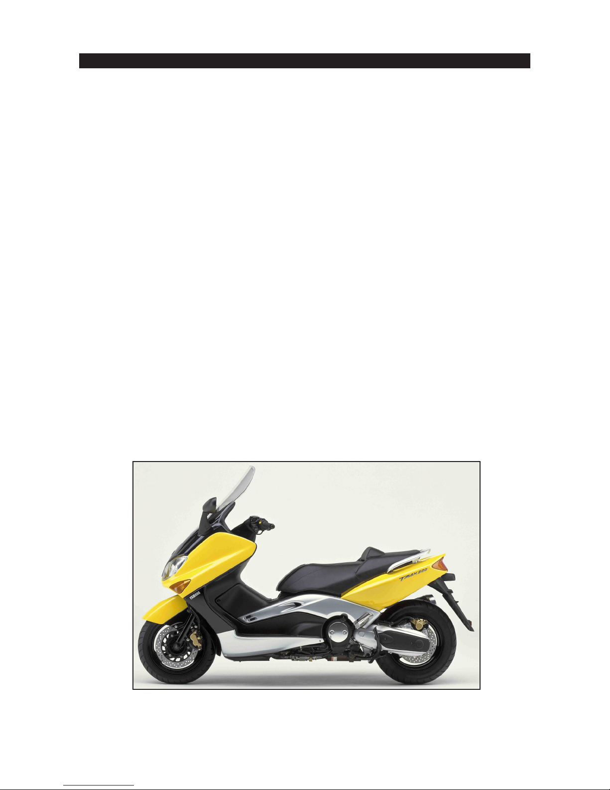
XP500 TMax Technical Orientation Guide
FEATURES AND BENEFITS
Offering high levels of performance, comfort and sophistication, the new TMax superscooter looks
sure to make as great an impression on the powered two wheeler market as the first Yamaha YZFR1 made in the motorcycle scene.
ENGINE FEATURES
n 499cc liquid cooled 4-stroke parallel twin
engine
n DOHC 8 valve engine
n High capacity V-belt transmission
n Horizontally opposed reciprocating balancer
n Wet multiple plate automatic centrifugal
clutch
n New design air intake route and air filter case
n Low position radiator
n Semi dry sump with oil cooler
n Non adjustable 2-stage silent chain drive train
CHASSIS FEATURES
n Motorcycle-type high rigidity diamond shape
frame
n Motorcycle-type front fork
n Highly rigid swingarm
n 14 inch front and rear wheels
n Motorcycle-type hub with fixed rear wheel axle
n Sport bike type weight distribution
n 50º lean angle
n 33 liters luggage compartment
n 1 piece dual seat with 3-stage adjustable
backrest
ELECTRICAL FEATURES
n Dual multi-reflector headlight
n Stylish combination taillight
n Automobile-type meter panel with extensive
information
n High capacity power supply
n Anti-theft alarm pre-wiring
n Grip warmer pre-wiring
n Mobile phone charger pre-wiring
1
Page 2
XP500 TMax Technical Orientation Guide
ENGINE SYSTEM
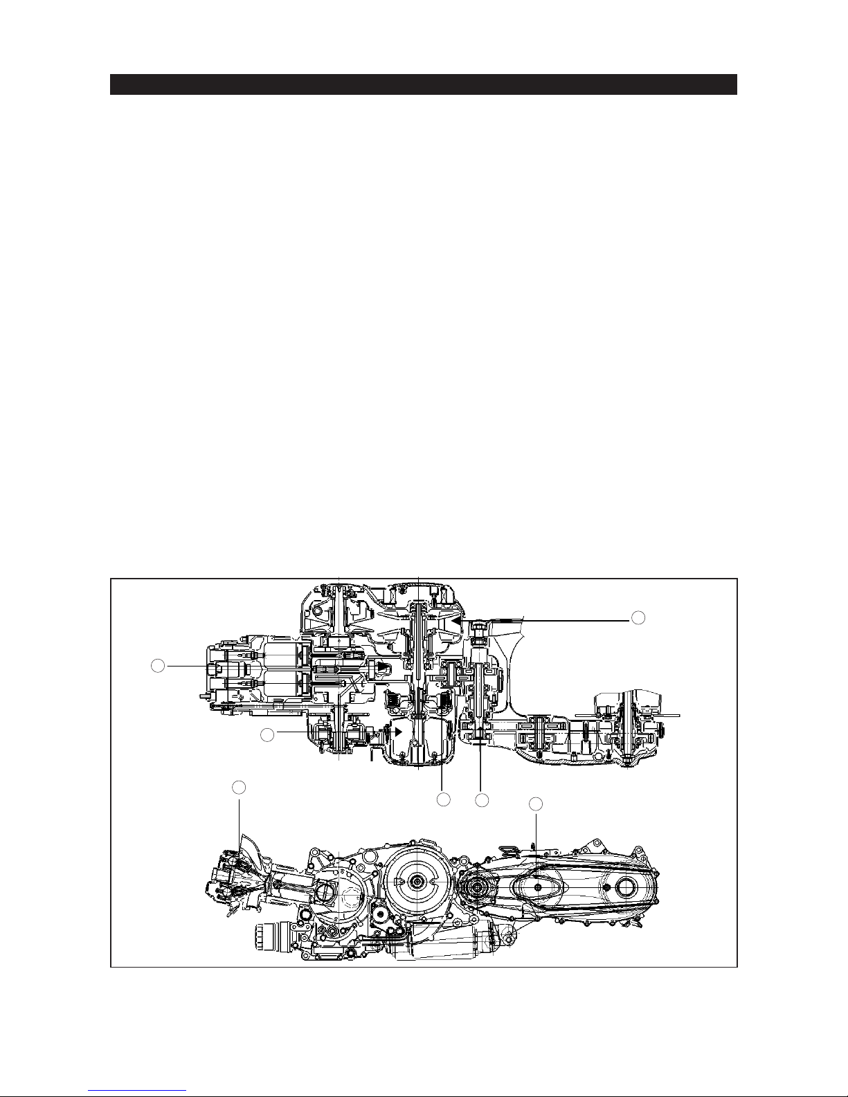
Displacing 499 cc, the TMax’s highly-advanced fully automatic twin-cylinder DOHC liquid-cooled
4-stroke 8-valve engine is one of the most powerful designs available on scooters today.
A key feature of its configuration is that unlike most traditional scooter engines which pivot as one
unit with the rear suspension, this engine is fixed rigidly into the TMax’s strong tubular diamond-shape frame
in order to achieve higher levels of chassis rigidity for enhanced handling performance. The swingarm is
mounted to a pivot point at the rear of the engine, thereby keeping unsprung weight low for more responsive
rear suspension action.
Another innovative feature is the horizontal configuration of the engine that keeps the centre of gravity
low for easy handling and also gives extra storage space under the dual seat.
ENGINE FEATURES
n Parallel twin with 360 degree crankshaft
n 66 mm bore and 73 mm stroke
n 10.1 :1 compression ratio
n Left side drive cam chain for reduced engine width
Horizontal compact cylinder head
Horizontally opposed reciprocating balancer
Semi dry sump
High capacity V-belt transmission
Wet multiple plate automatic centrifugal clutch
Non adjustable 2-stage silent chain drive train
Pivot coaxial drive shaft eliminates chain backlash
4
2
3
1
5
7
6
2
Page 3
XP500 TMax Technical Orientation Guide
CYLINDER HEAD
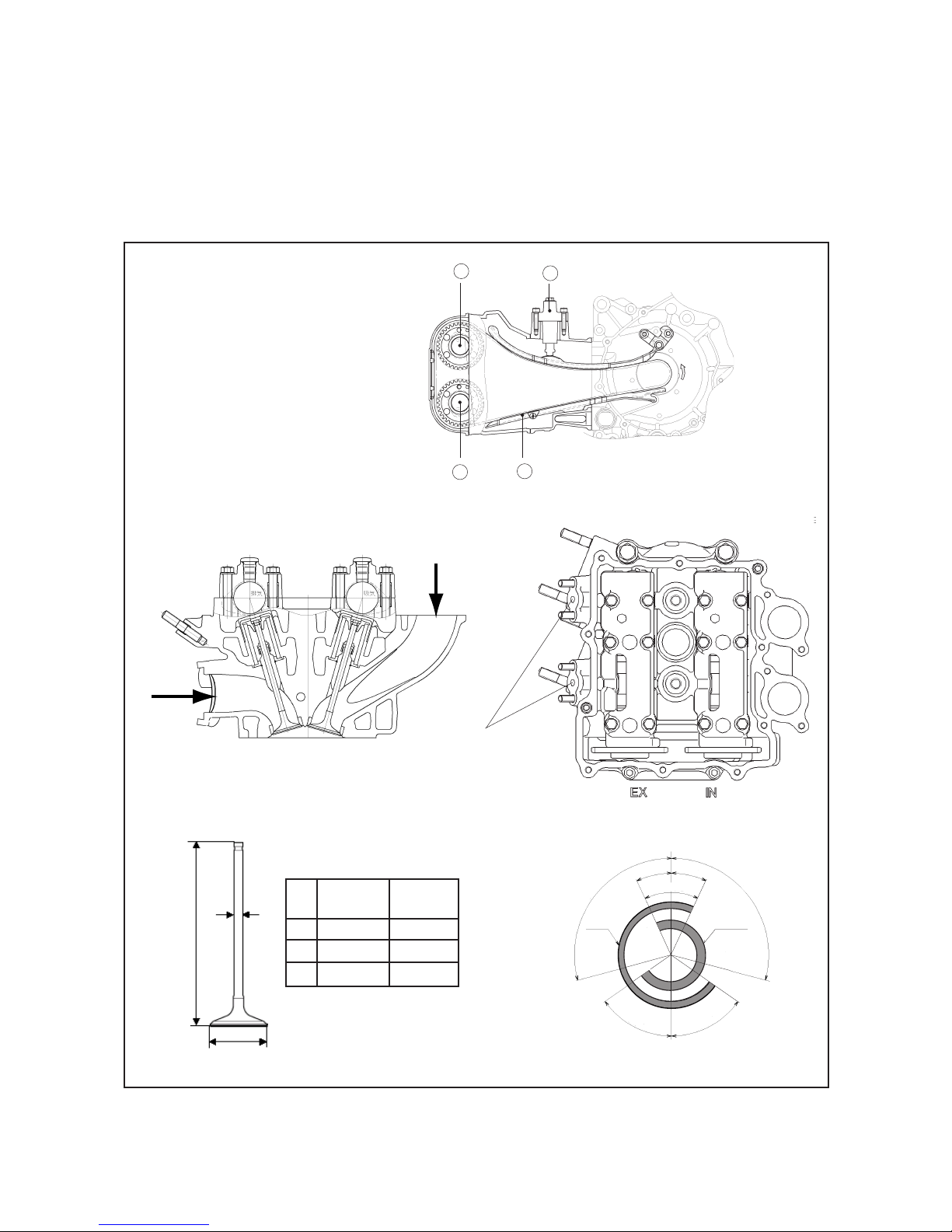
n 4 valves per cylinder, DOHC
n Torsion type auto cam chain tensioner (similar to YZF-R1)
n “Shim-under-bucket” valve adjustment for long maintenance interval (same as YZF-R1/YZF-R6)
n Valve clearance at cold engine condition:
Intake : 0.15 - 0.20 mm
Exhaust: 0.25 - 0.30 mm
Intake camshaft
Cam chain tensioner
Exhaust camshaft
Silent cam chain
Exhaust
port
Intake
port
1
3
4
Air Induction
Ports
2
(2)
(1)
(3)
(2)
(3)
(1)
Intake valve
(mm)
25.0
4.0
83.3
Exhaust valve
(mm)
22.0
4.0
82.8
TDC
25º
105º
EX
25º
OL 50º
BDC
105º
IN
55º55º
VALVE TIMING
3
Page 4
XP500 TMax Technical Orientation Guide
CYLINDER
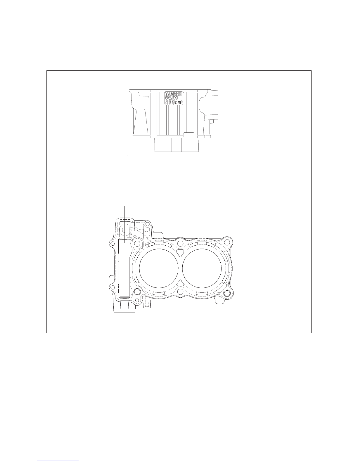
n New liquid-cooled cylinder body for low weight
n Left side cam chain drive for reduced engine width
n Ceramic composite cylinder coating for increased cooling and longer wear life
Side view
Side cam chain drive
ø 66.0 mm ø 66.0 mm
Top view
4
Page 5
XP500 TMax Technical Orientation Guide
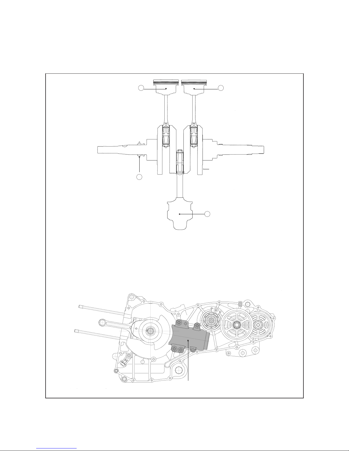
CRANKSHAFT / BALANCER
n New design crankshaft uses replaceable full circumference plain bearings
n Horizontally opposed reciprocating balancer for excellent vibration reduction
This type achieves same vibration reduction as 3 balancer shafts to reduce primary and secondary inertial forces, while requiring less space.
Piston cylinder #1
1
Piston cylinder #2
Cam chain drive gear
Balancer piston
3
Bearing size indication, reading from left to right (ex. 1 2 3 4 5):
Left main bearing
Right main bearing
Conrod bearing cylinder #1
Conrod bearing balancer cylinder
Conrod bearing cylinder #2
2
bearing size indication
4
Balancer cylinder
5
Page 6
XP500 TMax Technical Orientation Guide
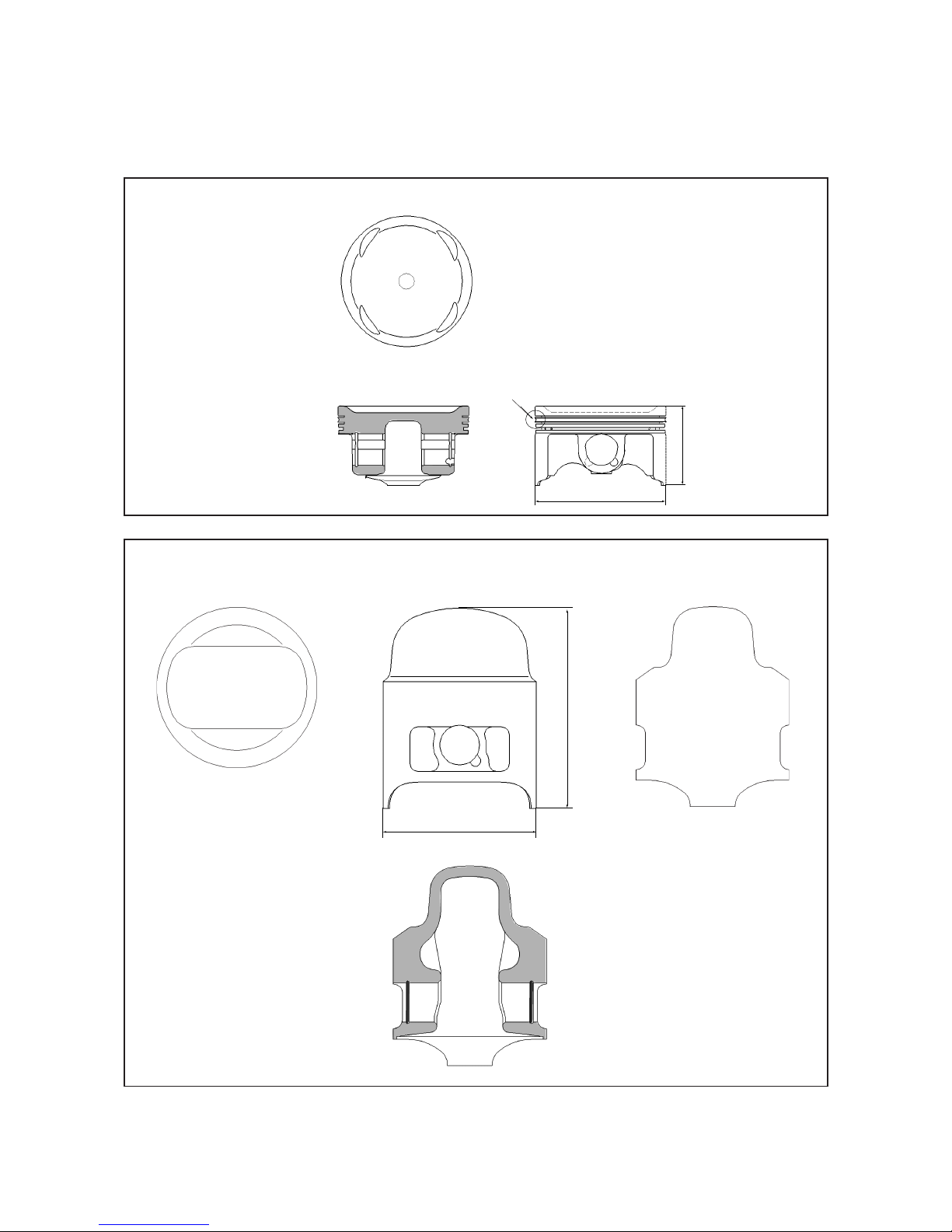
PISTON
n New combustion piston with V-groove between upper and lower compression rings for improved
sealing
n Balancer piston for horizontally opposed reciprocating balancing system
COMBUSTION PISTON
Top view
V-groove
Cross-section Side view
ø 40 mm
ø 66
BALANCER PISTON
Top view Side view
ø 58
Front view cross-section
Front view
71.7
mm
6
Page 7
XP500 TMax Technical Orientation Guide
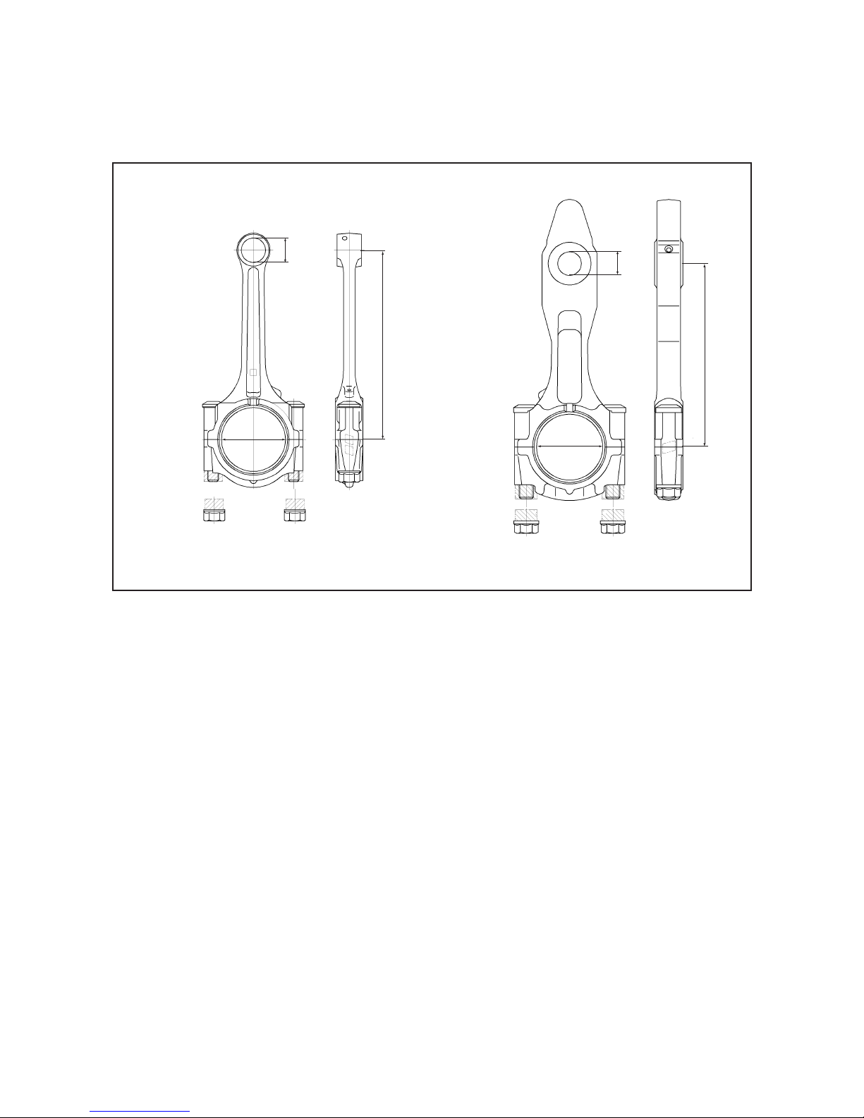
CONNECTING ROD
n Newly designed connecting rods: 2 for combustion, 1 for balancer
n New type connecting rod as integral part of the horizontally opposed reciprocating balancing
system
FOR COMBUSTION
16
mm
124.5 mm
45 mm 45 mm
FOR BALANCER
All connecting rods use the same 2-piece plain bearings
15
mm
117 mm
7
Page 8
XP500 TMax Technical Orientation Guide
TRANSMISSION SYSTEM
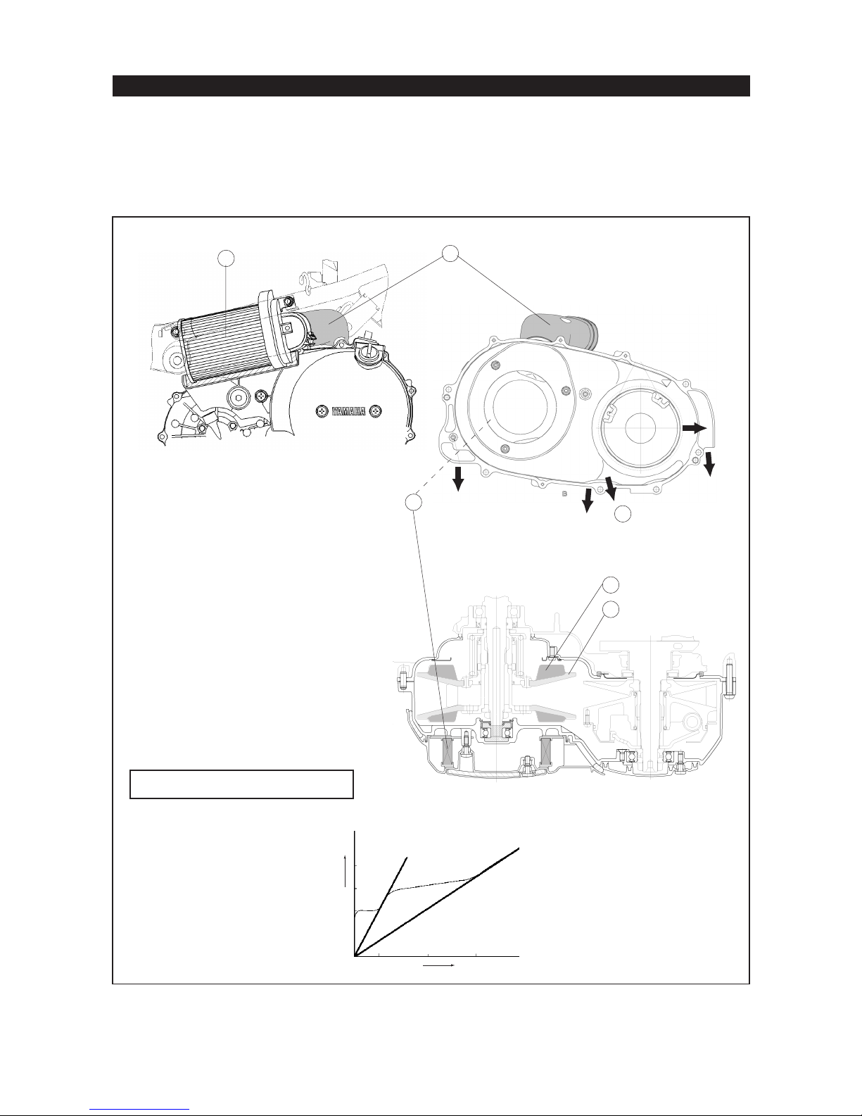
CONTINUOUSLY VARIABLE TRANSMISSION
n Highly efficient V-belt transmission in order to obtain high performance
n Newly designed cooling system with fins on both rotors of the secondary sheave for improved
cooling and higher belt durability
n Cooling system uses 2 air filters to provide high volume clean air cooling
1
Engine left side
Left transmission air filter
Air intake duct to transmission
Right transmission air filter
Air exhaust ports
Cooling fin
Secondary sheave
2
3
4
Engine right side
5
6
V-belt exchange: each 20,000 km
Speed shift rate diagram
Engine cross-section
rpm
speed
8
Page 9
XP500 TMax Technical Orientation Guide
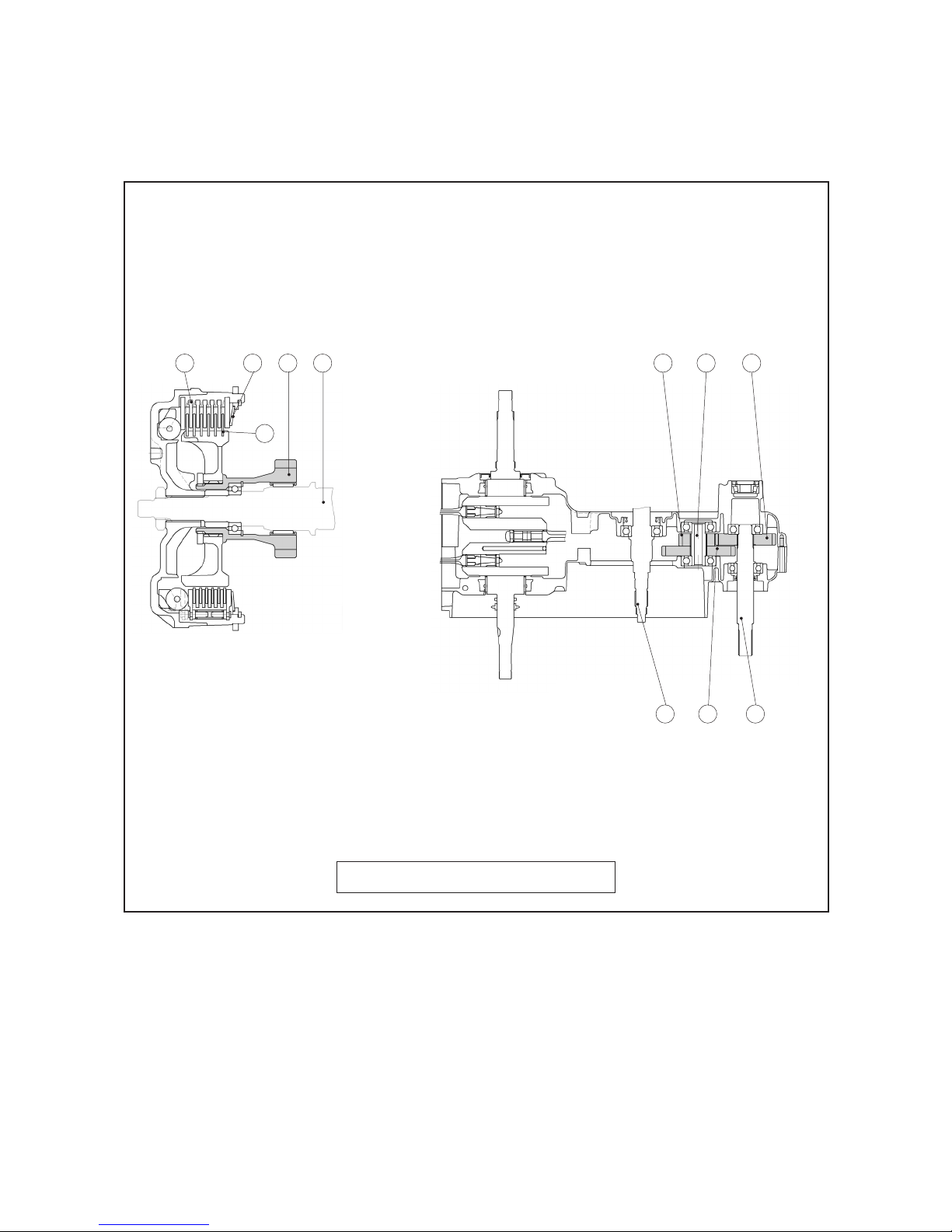
CLUTCH
n Wet type multiple plate centrifugal clutch for smooth power transmission and to meet XP’s
higher torque
n Clutch uses diaphragm type spring
Friction plates: 5 pieces
Clutch plates: 6 pieces
Diaphragm clutch spring
Primary drive gear
Main axle
1345
2
First pinion gear
Secondary shaft
First wheel gear
Drive axle
Primary driven gear
678
105
9
Transmission gear reduction ratio
= (primary driven gear / primary drive gear) x (first wheel gear / first pinion gear)
= (52 / 32) x (36 / 22)
= 2.659
Clutch-in revolution: 1800 ± 300 rpm
9
Page 10
XP500 TMax Technical Orientation Guide
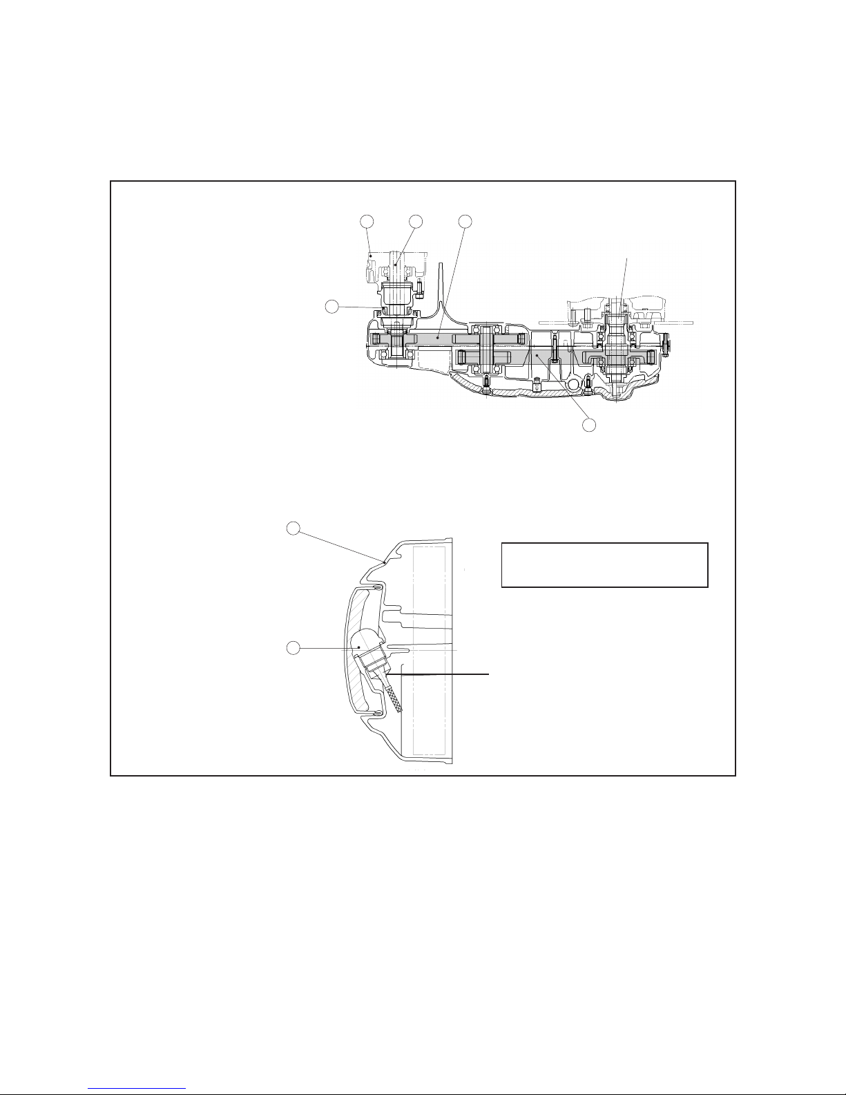
FINAL DRIVE
n Newly designed final drive with non-adjustable 2-stage silent chain for an efficient power trans-
mission, reduced noise and low maintenance
n High speed first stage chain with spring-type torque absorber for a further reduction of noise
n The final drive and the swingarm are integrated for improved rigidity and high speed stability
Crankcase
Drive axle
First stage drive chain
Second stage drive chain
Taper roller bearing
123
Mounted on rear wheel
clutch hub
5
Rear drive case
Oil dip stick
Gear ratio: (41 / 25) x (40 / 29) = 2.262
1
Final drive oil capacity: 700 cc
Type: SAE 80, hypoid
2
Oil level
4
10
Page 11
XP500 TMax Technical Orientation Guide
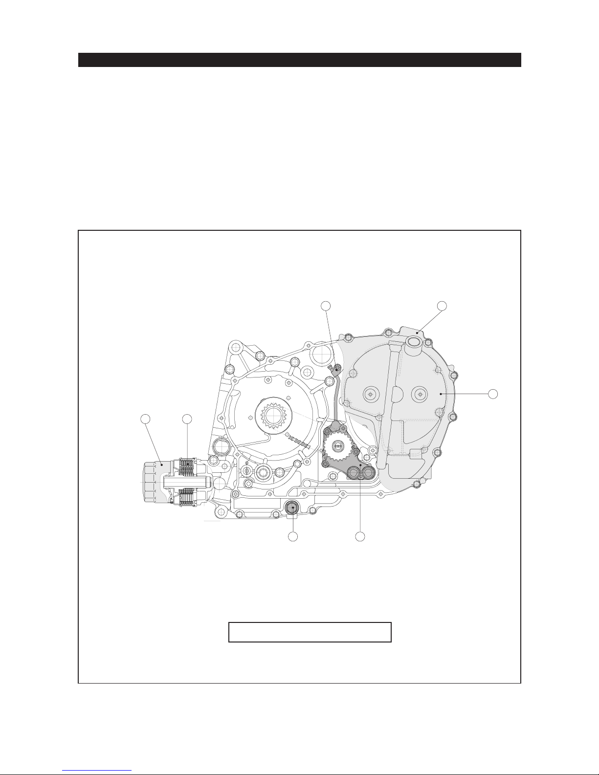
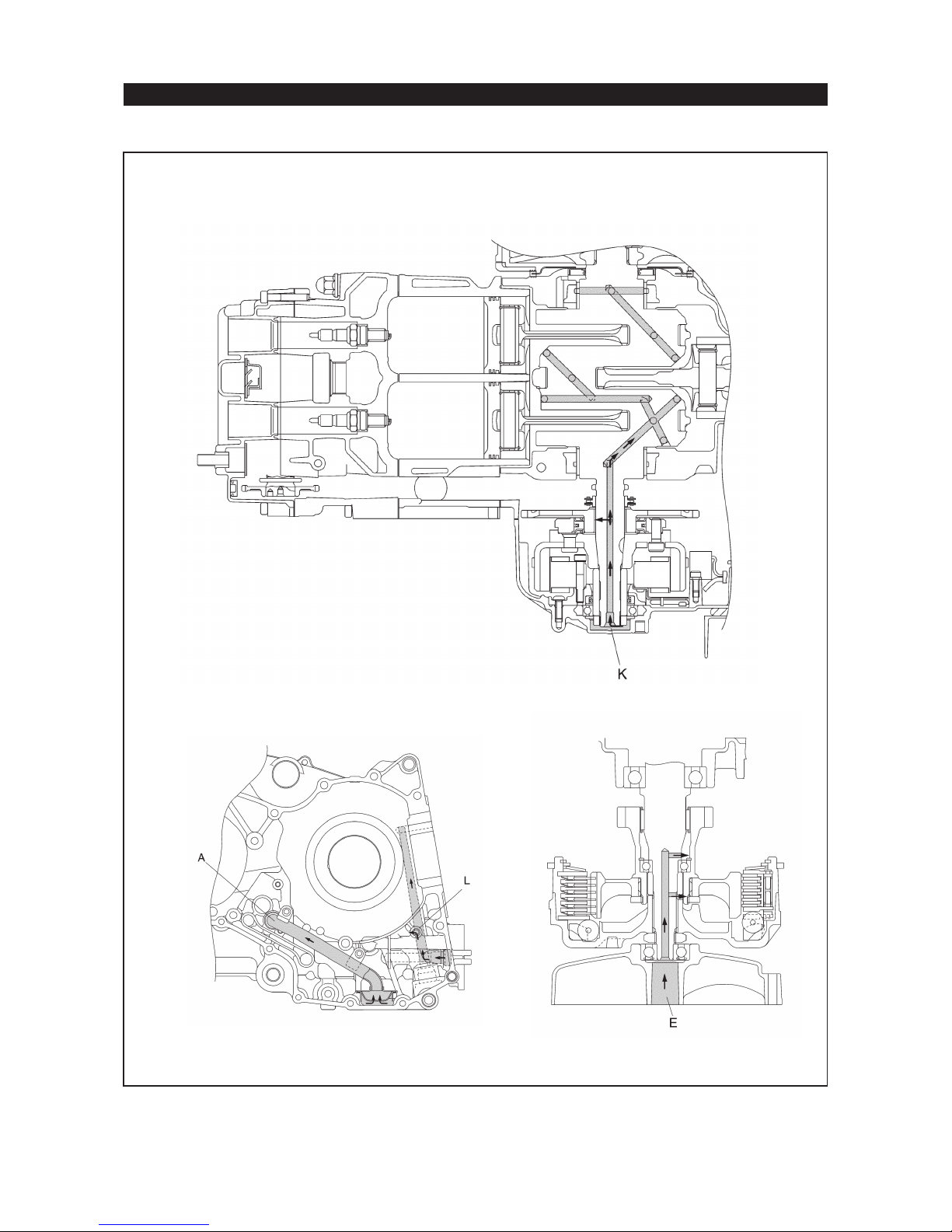
LUBRICATION SYSTEM
n Semi dry sump system for reduced engine size
n Oil tank is incorporated into the left crankcase cover
n Newly designed dual stage oil pump
n Liquid-cooled oil cooler with cartridge type oil filter (5DM-13440-00)
n New type oil drain bolt that allows oil from crankcase and oil tank to be drained at the same time
Dual stage oil pump brings oil from oil tank to respective areas of the engine, including a spray bar
over the starter gears and the stator assembly.
The oil pump also has a scavenging pump that returns the oil to the oil tank.
The scavenged oil fills the tank until it is full and then overflows back into the sump area to maintain a constant level in the sump.
Oil filter
Oil cooler
Oil spray bar
Crankcase cover
12
Oil tank space
Oil pump
Drain bolt
34
5
7
6
Engine oil capacity
Total amount : 3.6 liters = 2.2 liters in crankcase + 1.4 liter in oil tank
Without oil filter replacement : 2.8 liters
With oil filter replacement : 2.9 liters
Engine oil change: every 5,000 km
11
Page 12
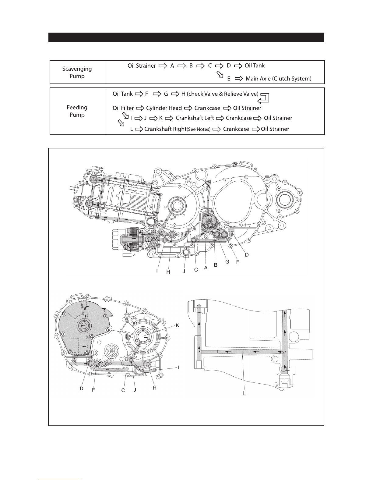
LUBRICATION SYSTEM
LUBRICATION FLOW CHART
XP500 TMax Technical Orientation Guide
12
Page 13
LUBRICATION SYSTEM
XP500 TMax Technical Orientation Guide
13
Page 14
XP500 TMax Technical Orientation Guide
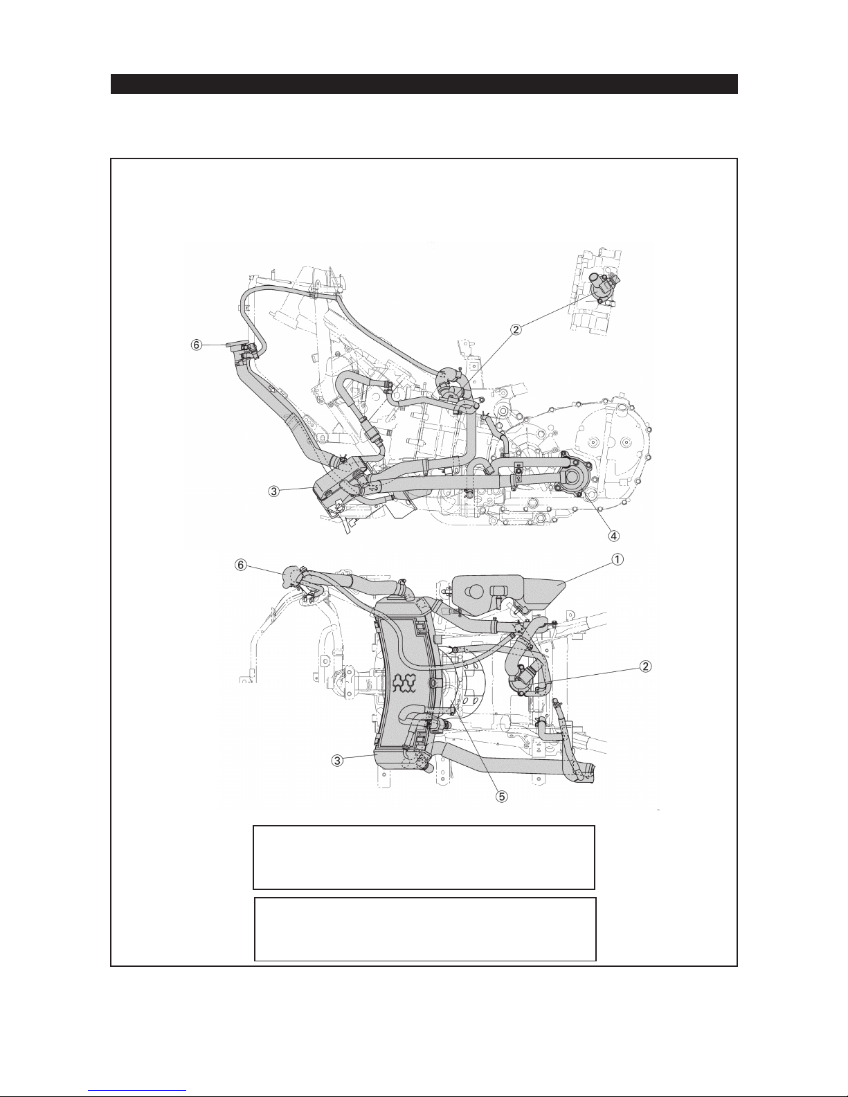
COOLING SYSTEM
n Low mounted radiator for design flexibility
n Automatic air bleed for easy maintenance
Coolant Reservoir Tank
Thermostat
Radiator
Water pump
Coolant Fan
Radiator Cap
Coolant temperature is less than 80
Coolant temperature is more than 80
Coolant temperature is less than 82
Coolant temperature is more than 82
Cooling system capacity: 1.5 liter
Carburetor heating thermostat:
±2 ºC: OPEN
±2 ºC: CLOSED
Main thermostat:
±2 ºC: OPEN
±2 ºC: CLOSED
14
Page 15
XP500 TMax Technical Orientation Guide
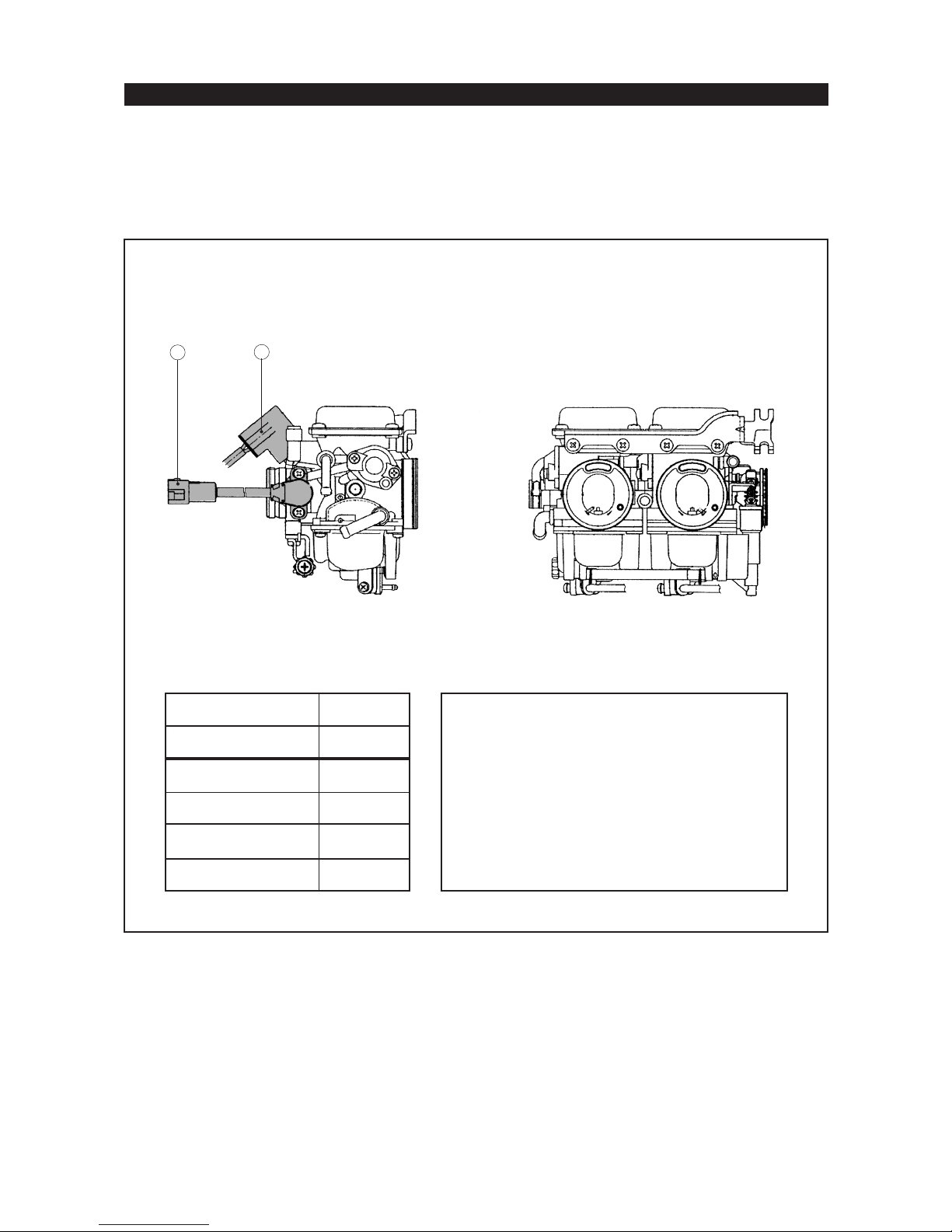
CARBURETION SYSTEM
n Twin BS30 round slide carburetors
n Automatic choke for easy starting
n Throttle Position Sensor to optimize ignition timing and reduce emissions
n Coolant type carburetor heater
n Pull-pull type throttle control
Auto Choke Unit
Throttle Position Sensor
2
1
Carburetor settings
Marking
Main jet
Jet needle
Needle jet
Pilot jet
Pilot screw turns out
5GJ1
#105
4DK4-3
0 - 0M
#22.5
2 1/2
Auto-choke electricity control.
By thermo switch.
coolant temperature is more than 60
coolant temperature is less than 55
By TCI Unit
more than 800 rpm: ON
less than 375 rpm: OFF
± 3ºC: ON
± 3ºC: OFF
15
Page 16
XP500 TMax Technical Orientation Guide
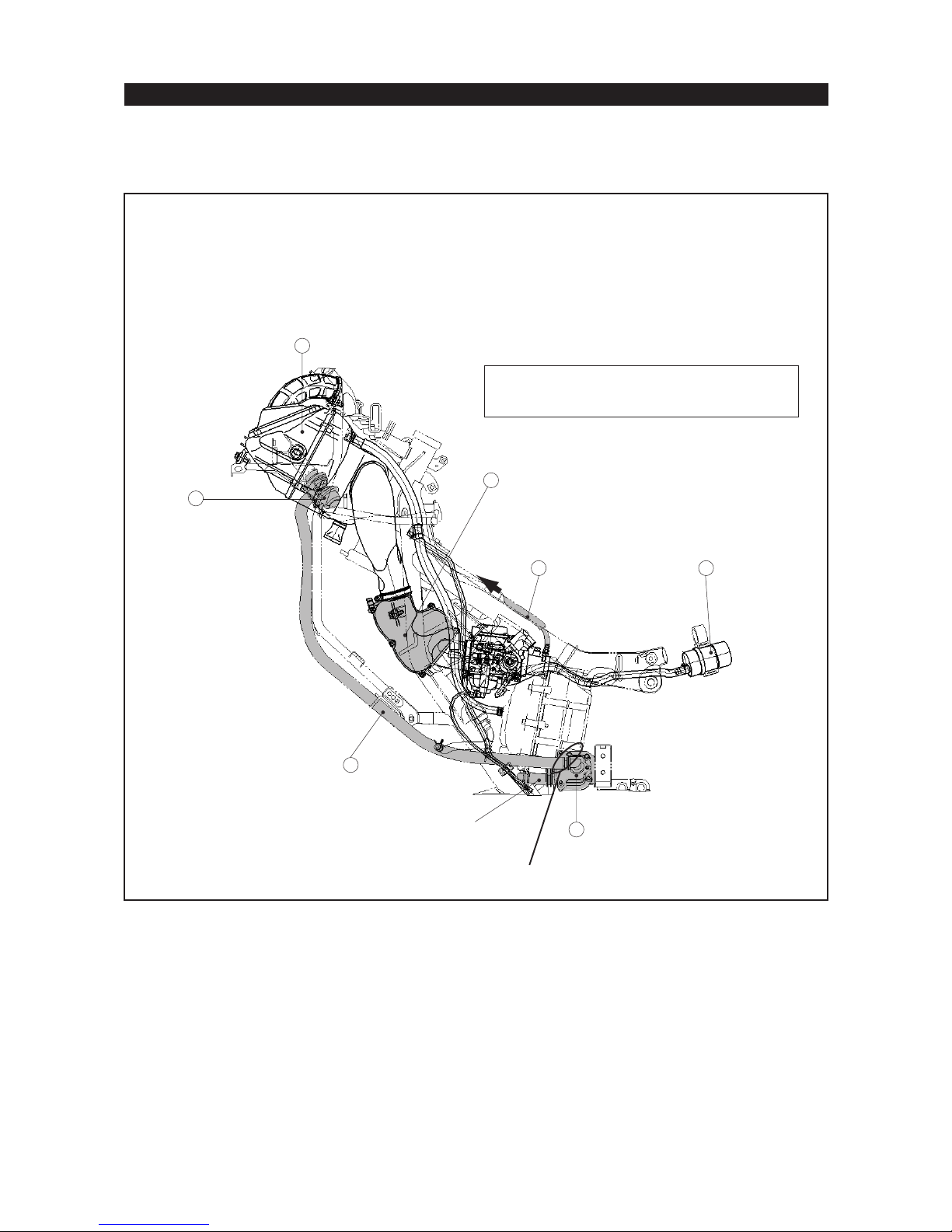
AIR INTAKE SYSTEM
n Air filter case position in upper front body cowling for effective use of space
n Air intake system uses noise reduction box
n Air Induction System for reduced emissions
Air filter case
Noise reduction box
Vacuum hose to Air Cut Valve
Fuel pump
1
7
Reed valve
Air hose (Reed Valve - Air Cut Valve)
Air Cut Valve
See Service Tips for CO adjustment and
Air Induction System check procedure
2
34
6
To exhaust port
5
BLOCK HERE FOR CO ADJUSTMENT
16
Page 17
XP500 TMax Technical Orientation Guide
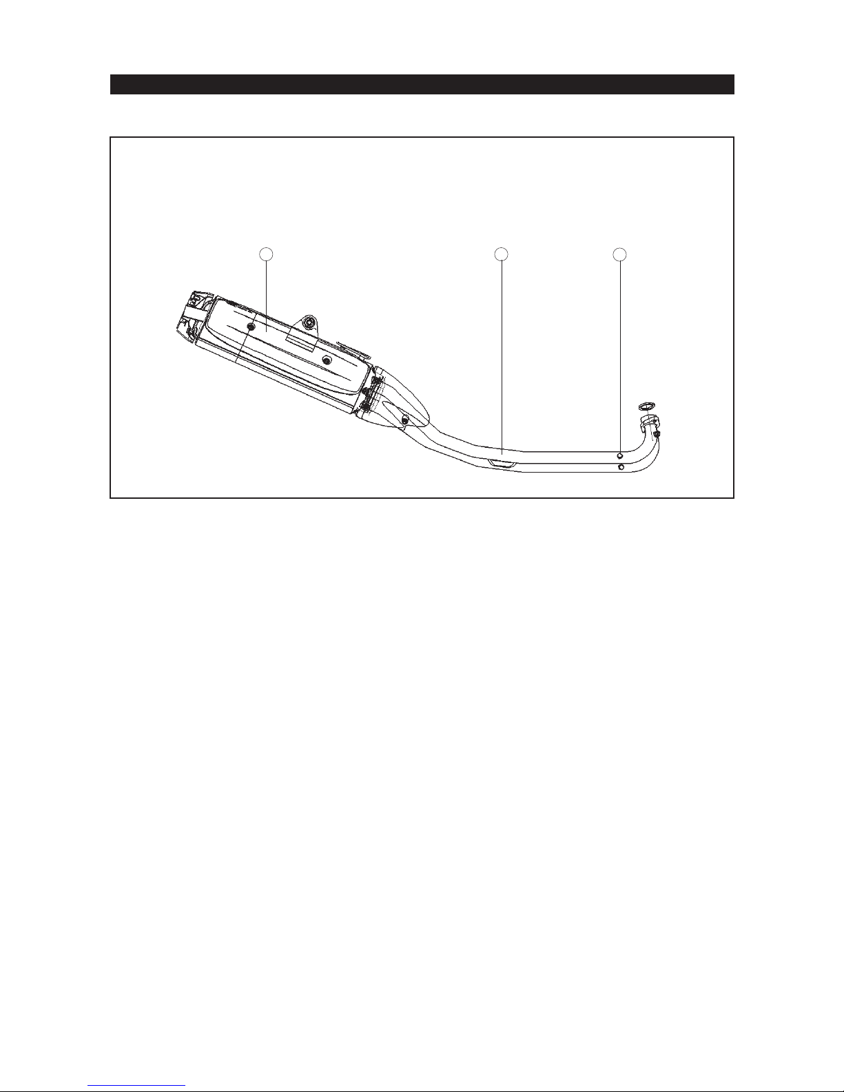
EXHAUST SYSTEM
n 2 into 1 stainless exhaust pipes and stainless muffler
Muffler
Exhaust Pipe
EGA connection
12
3
17
Page 18
XP500 TMax Technical Orientation Guide
CHASSIS
Like the all-new engine, the TMax’s advanced high-rigidity chassis has been developed using some
of the latest motorcycle technology in its frame and suspension designs.
n Sports bike type front and rear weight distribution of 47% and 53% respectively
n Ground clearance: 140 mm
n 50º lean angle
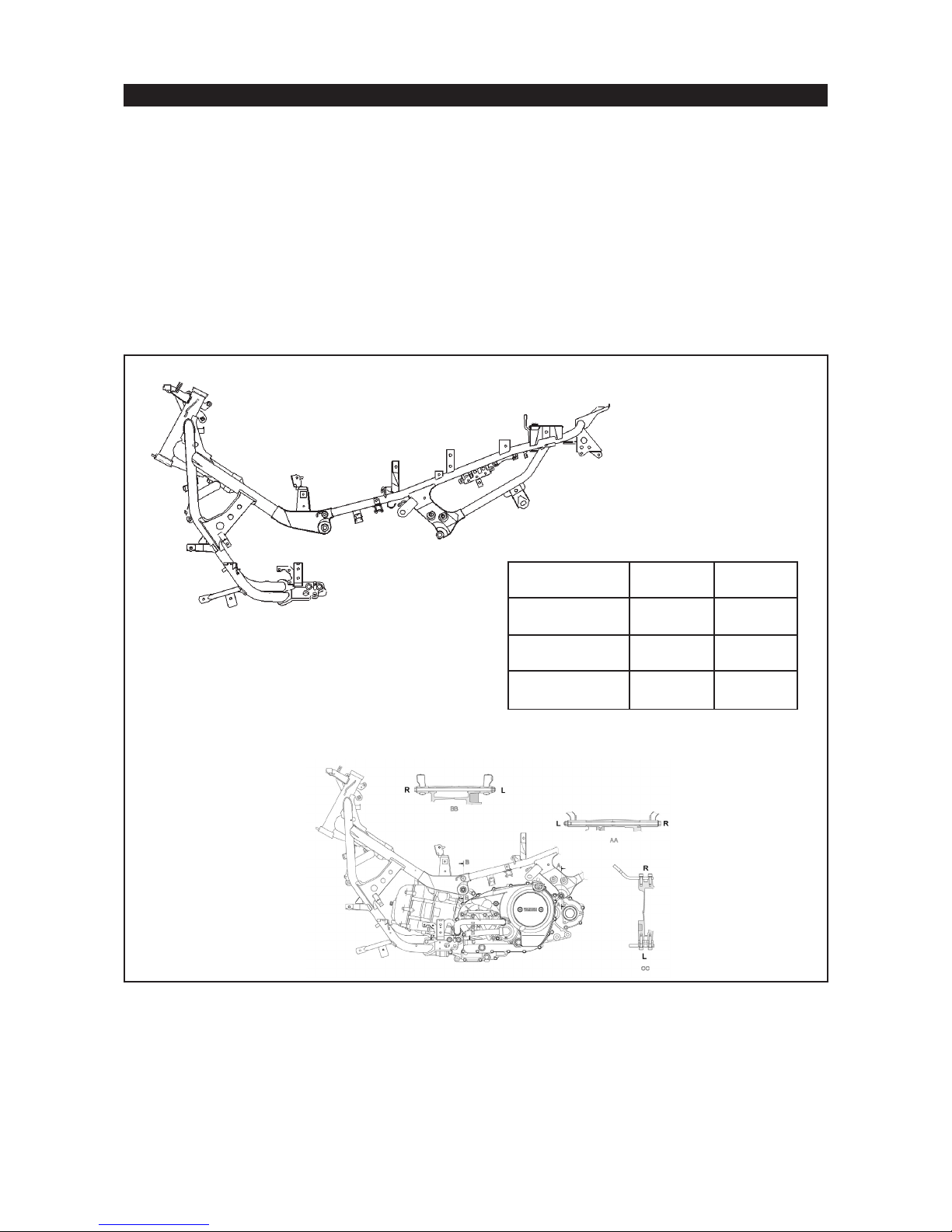
FRAME
n Newly designed tubular diamond shape frame
n Frame uses engine as a stressed member for added rigidity and enhanced handling performance
n Total configuration keeps centre of gravity low and wheelbase short
Overall length
Wheelbase
Min. turn radius
Engine mounting positions
References
XP500 YP250
2,235 mm 2,120 mm
1,575 mm 1,540 mm
2.8 m 2.6 m
18
Page 19
XP500 TMax Technical Orientation Guide
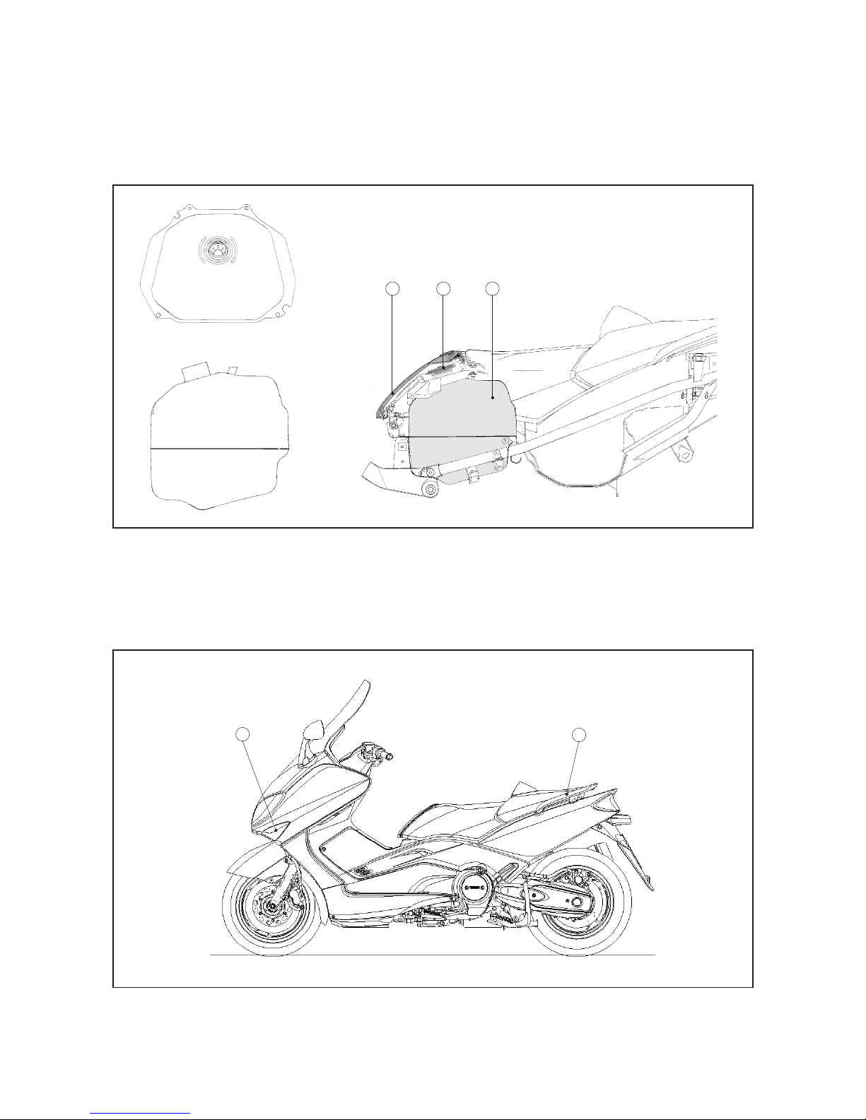
FUEL TANK
n Steel fuel tank just under rider seat
n Fuel lid in rider seat with easy access to fuel cap
n Fuel tank capacity is 14 liters
n Electric fuel pump for stabilized fuel supply uses external fuel filter
123
Fuel lid
Fuel tank cap
Fuel tank
BODYWORK
n Completely new aerodynamically-efficient sports styled bodywork
Integrated turn signal lights
Aluminium grab bar for improved passenger comfort
1
2
19
Page 20
XP500 TMax Technical Orientation Guide
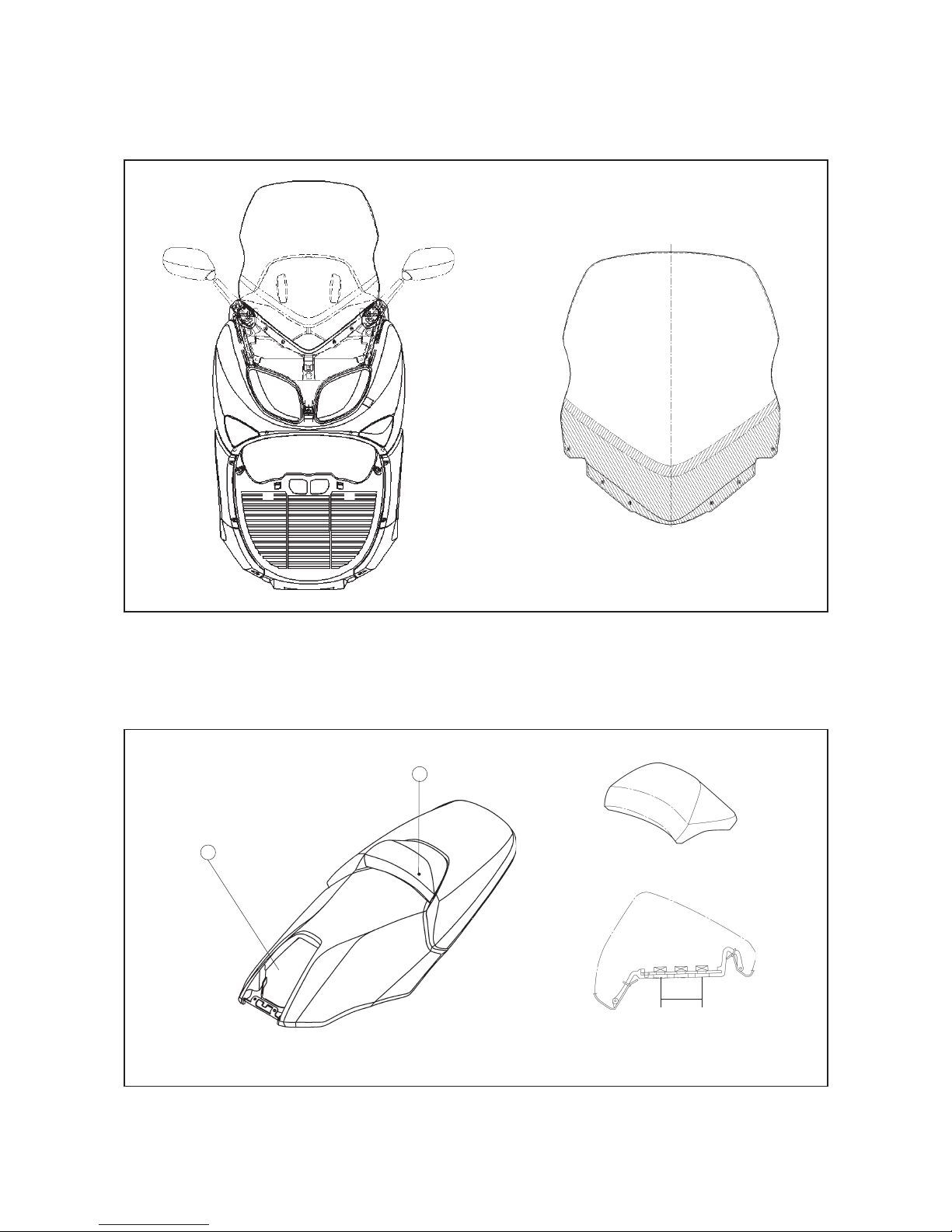
WINDSCREEN
n Large size windscreen for enhanced weather protection
n Newly designed cowling mounted mirrors
SEAT
n One piece deeply padded dual seat
n Rider seat features adjustable backrest offering 35 mm of movement in three stages
n Seat is locked at left and right side for enhanced security
Fuel lid
Adjustable backrest
1
2
35 mm
Seat height: 795 mm
20
Page 21
XP500 TMax Technical Orientation Guide
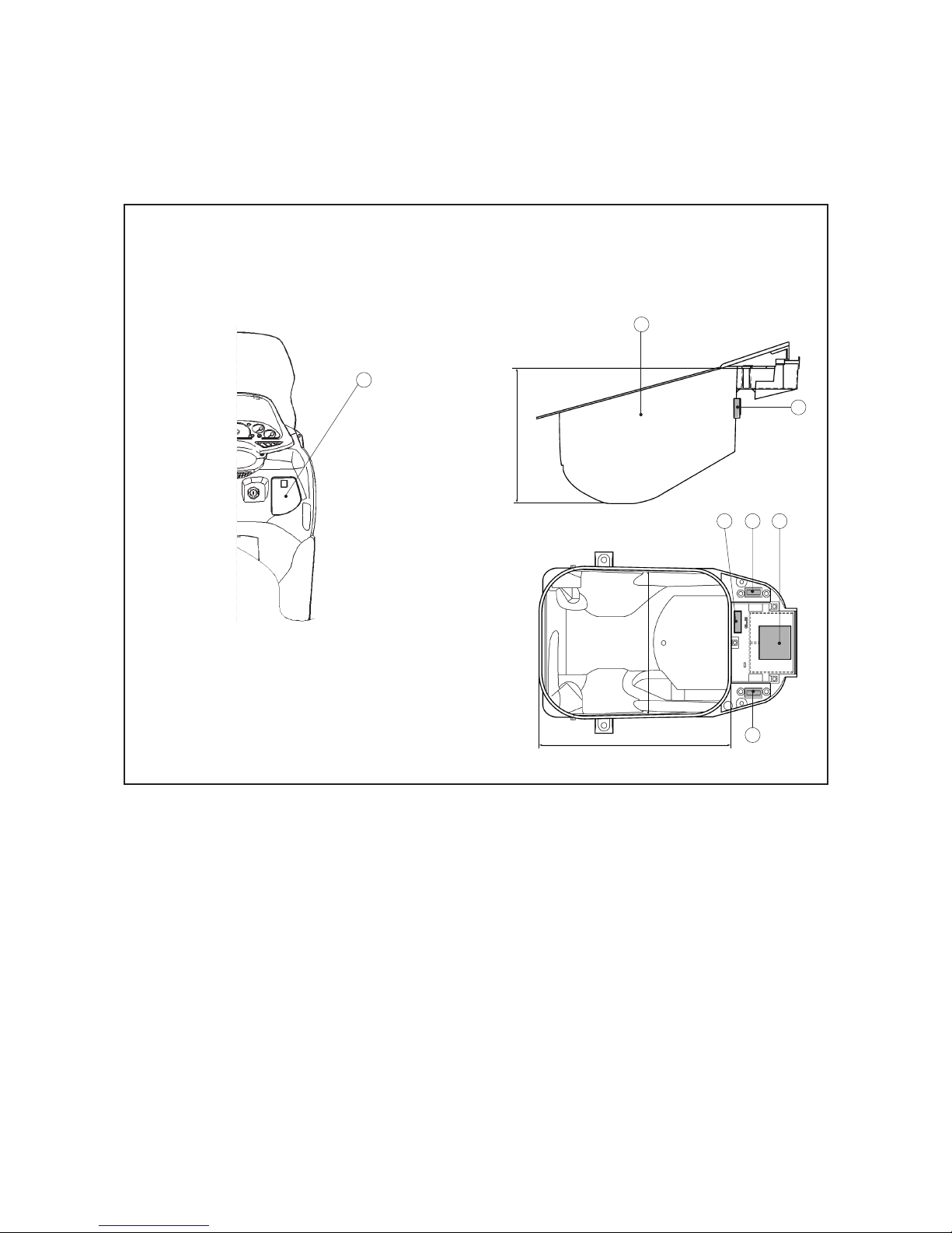
STORAGE COMPARTMENTS
n Small compartment in the right side front cowling of 1.2 liter for sunglasses, mobile phone, etc.
n Rear storage compartment under seat of 33 liters and it can hold a full face helmet or B4 size bag
n Rear storage compartment has an interior light, a special area for a U-lock and pre-wired for a 12V
accessory plug
Front storage compartment
Rear storage compartment
Interior light
1
Battery
Seat locks
Fuse box
2
3
336 mm
456
340 mm
21
5
440 mm
Page 22
XP500 TMax Technical Orientation Guide
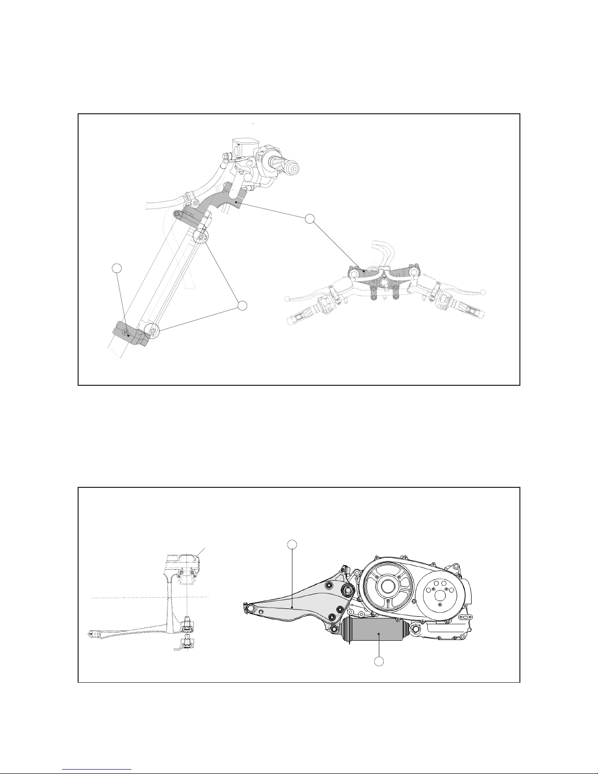
FRONT SUSPENSION
n Motorcycle type front suspension uses upper clamp and 38 mm fork tubes for increased high
speed stability
n Front wheel travel: 120 mm
Lower clamp
Upper clamp
Ball bearings
2
1
3
Top view
Oil level: 135 mm
Oil type: SAE 7.5 WT
REAR SUSPENSION / SWINGARM
n Single pull type rear shock absorber horizontally positioned underneath the engine for low centre
of gravity and increased storage space
n Swingarm and final drive are combined for improved rigidity
n Swingarm pivots independently of engine for more responsive suspension reaction
n Rear wheel travel and shock absorber stroke: 120 mm
Top view of swingarm
Final drive
Swingarm
Shock absorber
1
2
22
Page 23
XP500 TMax Technical Orientation Guide
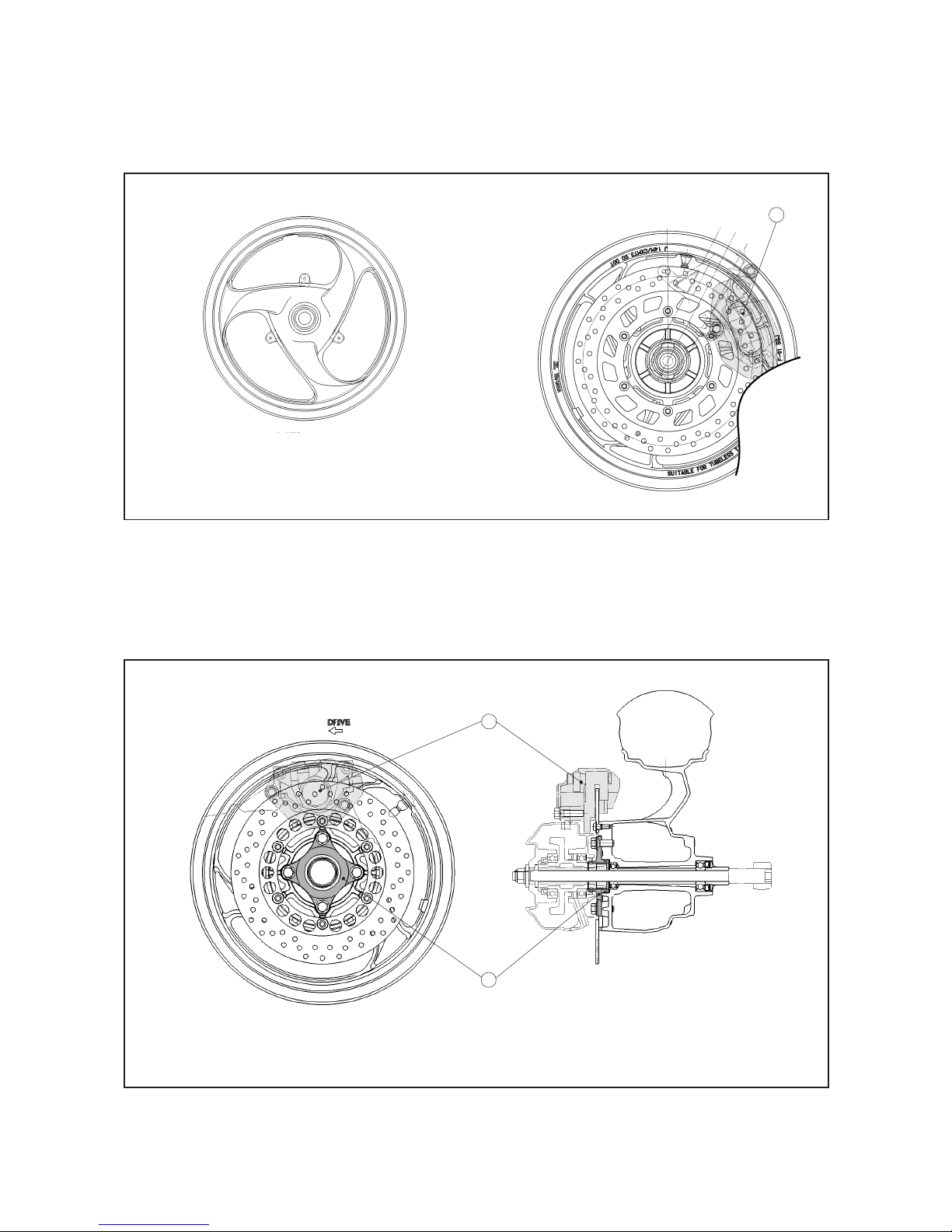
FRONT WHEEL / TIRE / BRAKE
n New 14 x MT 3.50 cast wheel
n Front disc brake diameter: 282 mm
n Front brake: two piston pin slide-type caliper
Front wheel
Front brake caliper
Tires.
Dunlop : D305FA 120/70-14 M/C 55S
Bridgestone : HOOP B03 120/70-14 M/C 55S
REAR WHEEL / TIRE / BRAKE
n New 14 x MT 4.50 cast wheel
n Rear wheel uses motorcycle-type clutch hub and fixed axle for enhanced stability
n Rear disc brake diameter: 267 mm
n Rear brake: 1 piston pin slide-type caliper
1
Rear brake caliper
Clutch hub
Tires.
Dunlop : D305 150/70-14 M/C 66S
Bridgestone : HOOP B02 150/70-14 M/C 66S
23
1
2
Page 24
XP500 TMax Technical Orientation Guide
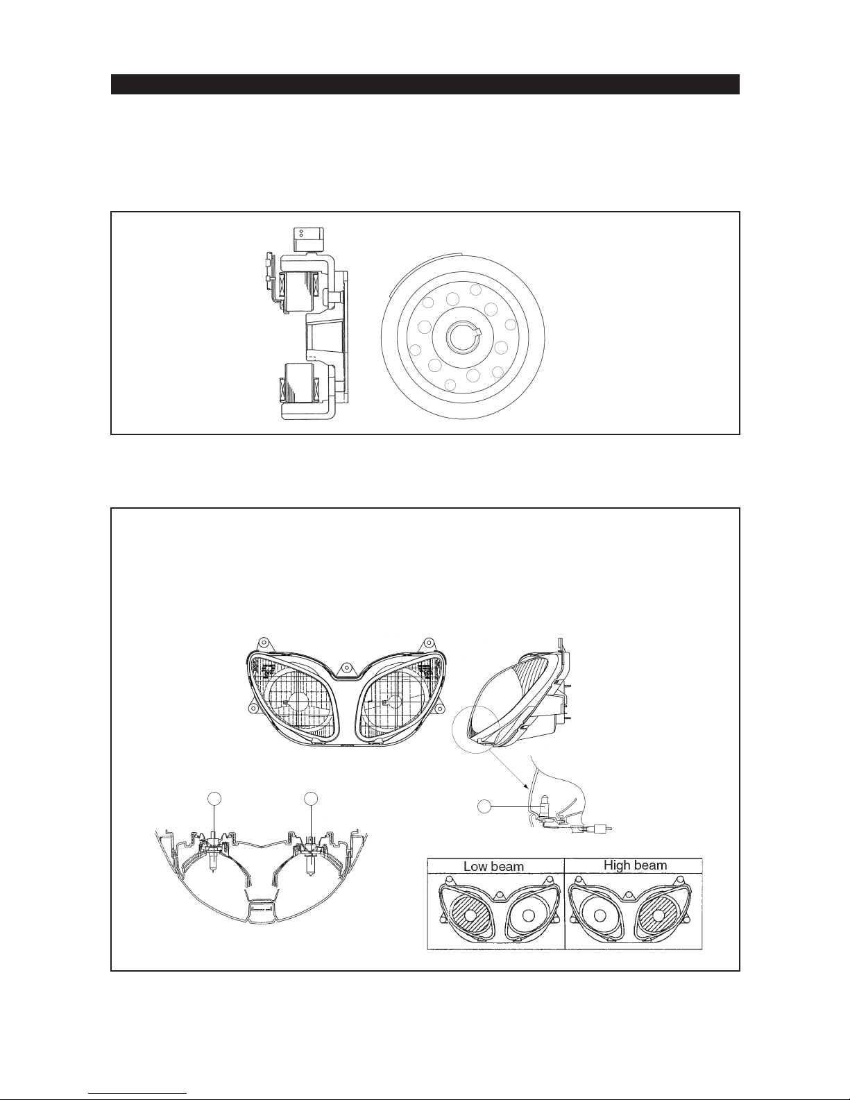
ELECTRICAL SYSTEM
GENERATOR
n The generator supplies ample power for electrical accessories
n Generator capacity: 22A, 14V @ 5000 rpm
n The optional electrical accessories are: mobile phone charger, grip warmers and anti-theft alarm system
HEADLIGHT ASSEMBLY
n Newly designed multi-reflector dual headlight
Low beam : 12V, 55W (H7 - 12V, 55W)
High beam : 12V, 60W (H4 - 12V, 60/55W)
Auxiliary lights : 12V, 5Wx2
For UK specifications, the positions of the left and right headlights are opposite
12
3
24
Page 25
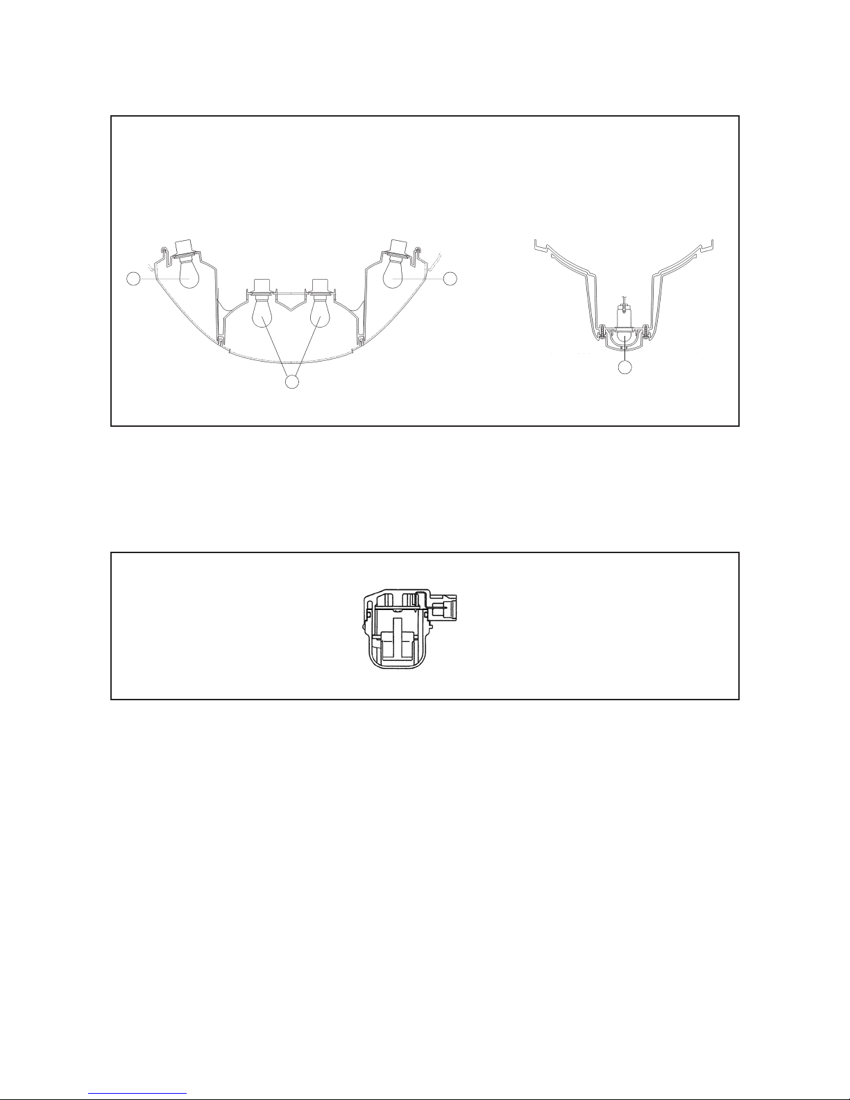
TAILLIGHT ASSEMBLY
n Newly designed dual taillight
Tail / brake light : 12V, 21/5W
Turn signal light : 12V, 21W
License plate light : 12V, 5W
XP500 TMax Technical Orientation Guide
Taillight
22
1
LEAN ANGLE CUT-OFF SWITCH
License plate light
3
Shuts off fuel pump if TMax falls on its side with running engine
Switch can not be activated if TMax is leaned over while cornering
If activated, the main switch must be turned “off” and then back “on” again to start the engine
ANTI-THEFT ALARM PRE-WIRING
n Main wiring harness is pre-wired from factory with connectors for an aftermarket alarm system
n Location: behind left side body cover
GRIP WARMER PRE-WIRING
n Main wiring harness is pre-wired from factory with connectors for an aftermarket grip warmer
n Location: under handlebar cover
MOBILE PHONE CHARGER PRE-WIRING
n Main wiring harness is pre-wired from factory with connectors for an aftermarket mobile phone charger
n Location: behind right side body cover
25
Page 26
XP500 TMax Technical Orientation Guide
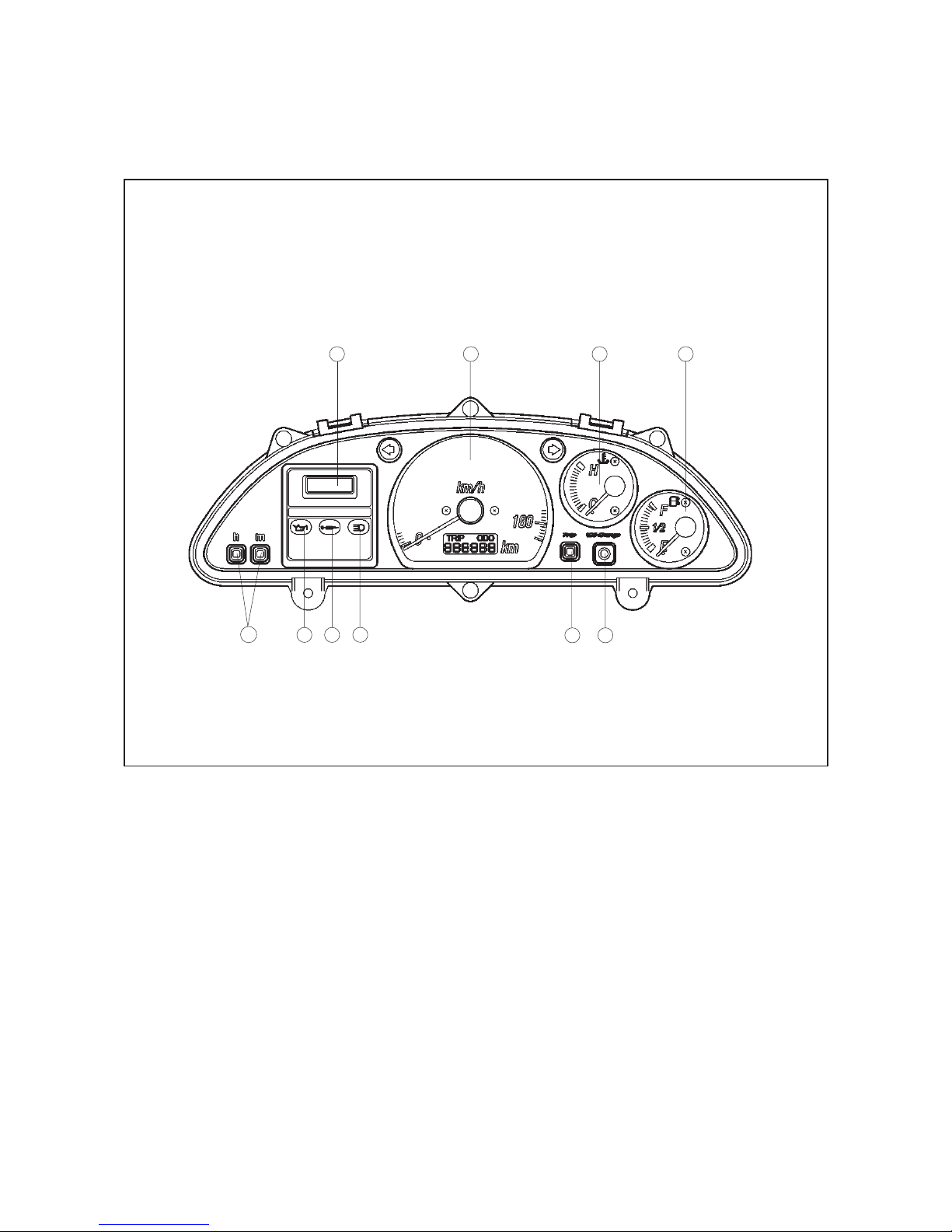
INSTRUMENTATION
n Automobile-style instrument panel for extensive information and easy reading
n Speedometer uses electronic front wheel speed sensor (same type as FZS600)
n Main switch has luminescent ring (similar to YP250)
Digital clock
Speedometer with integrated trip/odometer
Coolant temperature gauge
Fuel gauge
Oil indicator reset button
1234
10
9
8
Trip meter reset button
High beam indicator
V-belt change indicator
Engine oil change indicator
Time set buttons (left minutes / right
hours)
567
l Oil change indicator lights up at 1,000 km, 5,000 km and then every 5,000 km.
l V-belt indicator lights up every 20,000 km.
See Service Tips for details.
26
Page 27

XP500 TMax Technical Orientation Guide
SERVICE TIPS
The Service Tips portion of the Technical Orientation Guide is designed to further familiarize you
with some key servicing points of the TMax. It is not designed to replace the TMax Service Manual.
For complete servicing details please refer to the Service Manual.
ENGINE OIL LEVEL CHECK
Start checking from cold engine condition.
n Put the TMax on the main stand on level ground and check that the oil is at minimum level in the
sight glass. If not, add enough oil to bring it up to the minimum level and start the engine for
about 2 to 3 minutes so the oil sufficiently circulates through the system.
n Turn the engine off and let it sit for a couple of minutes to allow the oil to settle into the sump
and recheck the level. Add oil to the tank if necessary until the oil is at the proper level in the
sight glass.
FINAL DRIVE OIL LEVEL CHECK
With the TMax still on the main stand:
n Remove the two screws and the plastic cover on the left side of the swingarm
n Remove the dipstick and wipe clean
n Reinsert the dipstick but do not screw it in
n Remove again and check the level. If it is below the full level add oil accordingly.
RADIATOR FILL
The radiator fill cap is located just inside the lower right side of the front fairing near the front tire.
COOLANT RESERVOIR
There is a small cutout on the right side cowl under the floorboard area to check the reservoir
coolant level. If coolant is below the minimum level, pull up the rubber floorboard mat and remove
the screw that holds the filler cap access lid and the cap to add coolant.
AIR FILTER REPLACEMENT
n Remove the mirrors and the windshield with the base, do not remove the windshield from the
base, to access the air box.
n Remove the airbox cover and air filter.
PROPER REMOVAL OF THE MIDDLE SIDE PANELS
Some caution should be taken when removing these panels to prevent damaging them.
n Remove the two allen screws from the front and the allen screw near the passenger footrest
n Now pull on the bottom of the panel to pop the tabs out of the rubber grommets
n Then push the panel upward from the bottom to pop out the top section.
FUEL PUMP AND FILTER
The fuel pump and filter are located underneath the right middle side panel.
27
Page 28

XP500 TMax Technical Orientation Guide
CARBURETOR ACCESS
Carburetor adjustment is easily accessible through the center of the floorboard. The vacuum plugs
for carburetor synchronization are on the intake manifolds and the fuel mixture screws for CO
adjustment are on the top of carburetors.
AIR CUT VALVE
The Air Cut Valve for the Air Induction System is located under the windshield on the left side of
the air box.
AIR INDUCTION SYSTEM REED VALVE
When performing the CO adjustment, be sure to block off the large hose to the reed valve located
under the left floorboard. This will prevent air from entering the system and giving inaccurate readings.
CO ADJUSTMENT / AIR INDUCTION SYSTEM CHECK PROCEDURE
CO ADJUSTMENT
1 Cut the secondary air supply by blocking the hose between the Air Cut Valve and the Reed Valve
(See pg.16 for Illustration).
2 Connect the exhaust gas analyzer to the head pipe fittings.
3 Disconnect the crankcase breather hose. This will prevent any oil contamination or combustion
blow-by from affecting the EGA readings.
4 Warm up the engine for several minutes at idle rpm.
5 Adjust the CO while maintaining the following conditions::
n Oil temperature : 65 ~ 75 ºC
n Coolant temperature : 75 ~ 85 ºC
n Intake vacuum : 33 ~ 39 kPa
n Idle revolution : 1150 ~ 1250 rpm.
CO measurement should be: 3.0%
AIR INDUCTION SYSTEM CHECK PROCEDURE
1 Adjust CO following the above procedure.
2 Restore the secondary air supply to the air induction system unit.
3 Check the CO reading while maintaining the above conditions (oil temperature, coolant tempera -
ture , intake vacuum and idle rpm).
4 CO reading should be: 0.5%
NOTE: Reconnect the crankcase breather hose and check the CO reading again. If the CO level is much
higher, the engine oil may be contaminated with gasoline or the engine may be suffering from poor
mechanical condition. Change the engine oil and check the CO level again. If the reading is still out of
specification, check the engine for a mechanical problem.
V-BELT TRANSMISSION AIR FILTERS
One of the V-belt transmission air filters is located under the left side panel next to the fuel tank and the
other one is inside the right crankcase cover in front of the secondary sheave.
HEADLIGHT BULB ACCESS
The head light bulbs can be accessed by reaching up under the front cowling.
TAILLIGHT AND REAR TURN SIGNAL BULB ACCESS
The taillight and turn signal bulbs can be accessed after removing the aluminium grab rail, middle and side
sections of the tail cowl.
28
Page 29

XP500 TMax Technical Orientation Guide
OTHER COMPONENTS LOCATED UNDER REAR COWL
n The Main fuse, starter relay, flasher relay, starter cut-off relay, fuel pump relay, seat lock cable junction
and regulator/rectifier are all located under the right side rear cowl.
n The stator, pick up coil and alarm connectors are located under the left side.
THERMO SENSOR AND THERMO SWITCH
The thermo switch for the auto choke is located directly on the thermostat housing and the thermo
sensor for the temperature gauge is next to the thermostat on the cylinder. The electric cooling fan is
mounted directly on the radiator and is controlled by a thermo switch mounted on the left upper
corner of the radiator.
REAR WHEEL REMOVAL
To remove the rear wheel, place the TMax on the main stand on level ground.
n Take off the plastic cover on the left side of the swingarm.
n Remove the axle nut.
n Remove the rear brake caliper from the swingarm.
n Loosen the axle pinch bolt on the right side.
n Remove the axle and spacer.
n Pull the wheel to the right to slide the hub out of the splines and pull the wheel out of the swingarm.
n Be sure to grease the hub splines before re-installation.
V-BELT REPLACEMENT
The V-belt on the TMax can be replaced by taking off:
l Right middle side panel
l Right floorboard
l Small shroud
l Rear passenger footpeg
l Muffler stay bolt
l Plastic cover from V-belt transmission cover.
n Move the fuel filter and pump out of the way.
n Remove the V-belt transmission cover while moving the muffler out of the way.
n Install two 45 x 6 mm bolts into the threaded holes of the secondary sheave.
n Tighten the bolts evenly until the secondary sheave is spread apart far enough so that the V-belt can be
removed.
n Install the new belt and remove the bolts.
To reset the V-belt indicator light, disconnect the 2-pin jumper connector for 2 to 5 seconds with the
main switch turned on, then reconnect it.
29
Page 30

XP500 TMax Technical Orientation Guide
CHECKING TDC AND CAM TIMING POSITION
n Remove the left and right floorboards as shown earlier.
n Remove the valve cover according to the service manual.
n Remove the inspection plug on the left crankcase cover just above the water pump.
n Remove the small cover on the front of the right side crankcase cover to access the primary
sheave nut.
n Rotate the primary sheave nut clockwise until the TDC mark on the rotor is aligned with the
mark in the inspection window. The number one cylinder will also be at TDC of its compression stroke
when the small holes on both camshaft sprockets are even with the cylinder head surface and facing
towards the intake side of the engine.
VALVE ADJUSTMENT PRECAUTION
Because of the near horizontal angle of the cylinder head, the exhaust valve lifters may have a tendency to
slide out of their pockets when the cams are removed. If this occurs the adjustment shim may fall out of the
valve retainer and damage the cylinder head if the engine is run in this condition.
To prevent this from happening, apply a small amount of grease to the adjusting shim and the valve
lifter before reassembly. This will hold the shim and lifter in place while the cams are reinstalled
and timed.
RESET ENGINE OIL CHANGE INDICATOR
To reset the engine oil indicator, push the oil indicator reset button on the instrument panel for 2 - 5
seconds. The required reset time is to prevent accidentally resetting the oil change indicator (i.e. the
counter in the igniter-unit). See also Self-diagnostics.
SELF-DIAGNOSTICS
The oil indicator light of the TMax has 3 functions:
n Oil indicator bulb check
n Indicate replacement timing of engine oil
n Indicate an electrical problem (self-diagnostics).
Function 1
The oil indicator lights up momentarily when the main switch is turned on, in order to indicate that the oil
indicator light bulb is working properly.
Function 2
The oil indicator lights up continuously in order to indicate that the engine oil has to be replaced.
It lights up initially at 1,000 km and 5,000 km, after that it lights up every 5,000 km (10,000 15,000 - etc.).
NOTE:
The mileage is counted by the igniter after every reset, it therefore is possible that the timing of the
light is different from the odometer reading.
30
Page 31
XP500 TMax Technical Orientation Guide
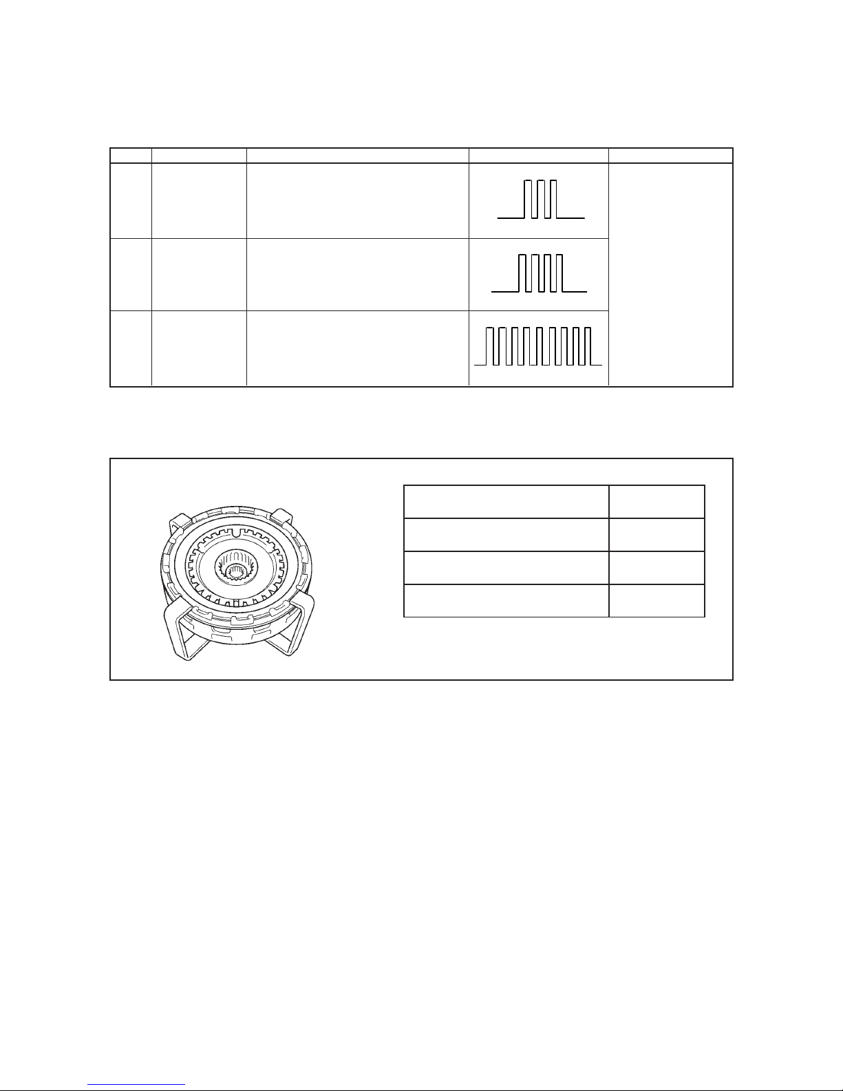
Function 3
If the igniter detects an electrical problem, the engine oil indicator will flash according to patterns mentioned
as Condition Codes in the table below.
Circuit Defect(s) System Response Condition Code Remarks
l Disconnected
TPS
l Short circuit.
l Mechanical
Malfunction.
Speed
l Disconnected
Sensor
Lean
l Disconnected
Angle
l Short circuit.
Switch
l Mechanical
Malfunction.
SPECIAL TOOLS
l The igniter-unit stays set to wide-open
throttle ignition timing.
l Oil indicator displays condition code.
l Oil indicator displays condition code.
l The system stops fuel pump operation.
l Oil indicator displays condition code.
There are three new special tools introduced for the TMax:
Light on : 0.5 s
Light off : 0.5 s
Pattern interval: 3.0 s
Primary Clutch Holder
Part Name
Primary Clutch Holder
Sheave Holder
Plain Bearing Installer/Remover
Part Number
90890-01482
90890-01481
90890-04139
31
Page 32
XP500 TMax Technical Orientation Guide
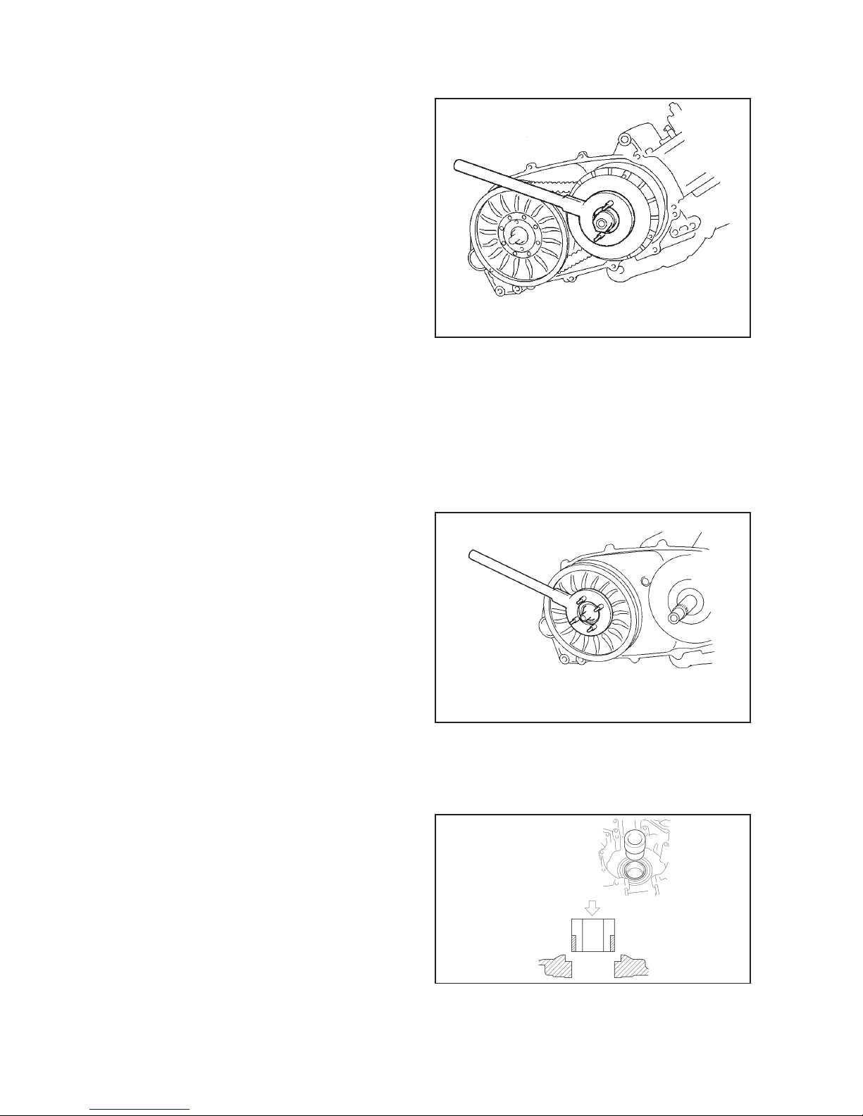
PRIMARY SHEAVE REMOVAL AND DISASSEMBLY
After the V-belt has been removed:
n Install the sheave holder on the primary sheave.
n Take off the nut.
n Take off the front sheave.
n Take off the rear sheave from the
crankshaft.
To disassemble the primary sheave:
n Remove the screws.
n Remove the sheave cap.
n Remove the cam.
n Remove and inspect the weights and sliders
for damage.
Clean and check the sheave surfaces for cracks or other damage. Clean the entire sheave assembly of the
old grease and repack it with 80 to 90 grams of the same special sheave grease as used on the YP250 and
re-assemble.
When re-installing the primary sheave on the crankshaft, be sure to grease the crankshaft splines with the
special grease and that the sheave plate splines are properly aligned with the crankshaft splines.
Sheave holder used on primary sheave
SECONDARY SHEAVE REMOVAL AND DISASSEMBLY
Follow the same procedures for the secondary
sheave removal as the primary sheave using the
opposite side of the sheave holding tool:
n Install the secondary spring compressor tool in
a vise.
n Install the secondary sheave onto the tool.
n Remove the nut and spring from the assembly.
n Then separate the sheaves by removing the collar
and pins from the cam.
Sheave holder used on secondary sheave
Clean and inspect all parts for wear or damage. Lube all sliding parts with assembly lube and reassemble
the sheave.
MAIN BEARING REPLACEMENT
Because the TMax uses full circumference plain
bearings, it is necessary to use the special bearing
installer/remover to remove and install them.
Use extreme caution when installing these
bearings to prevent damage.
For detailed drawings and instructions refer to the
XP500 Service Manual.
32
Page 33
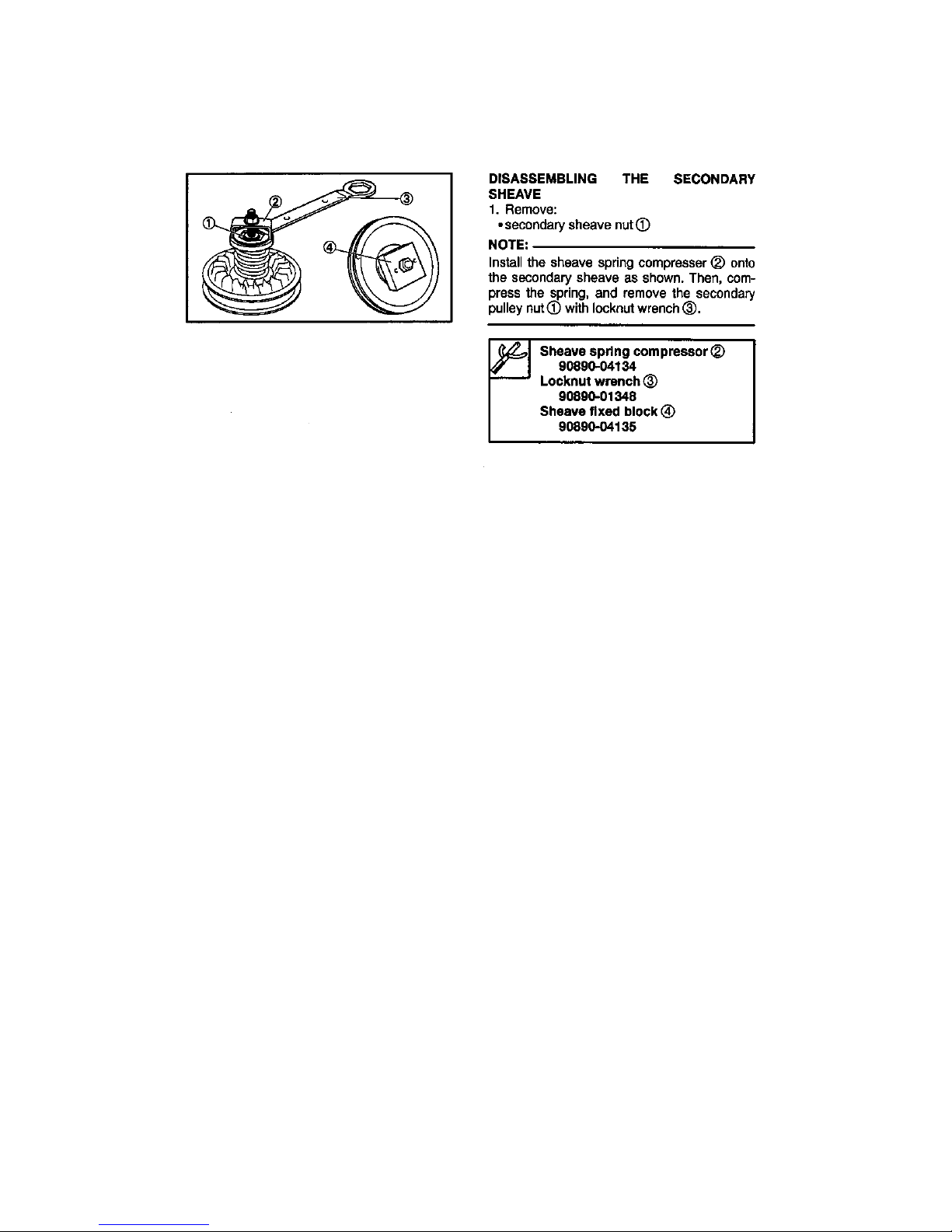
Following special tools are NOT new, but they are used only for ATV.
It is possible that motorcycle dealers have do not have the proper tools.
Page 34
XP500 TMax Technical Orientation Guide
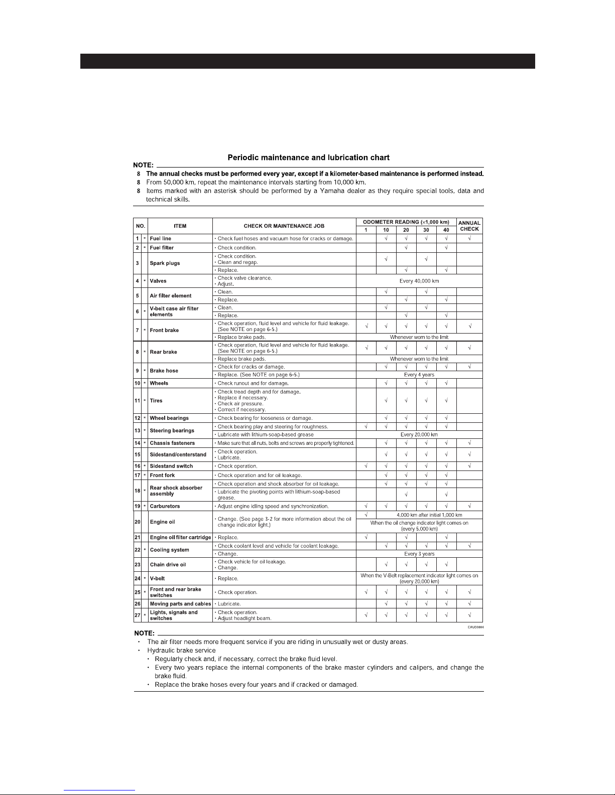
PERIODIC CHECKS AND ADJUSTMENTS
This chapter includes information necessary to perform recommended checks and adjustments. If
followed, these preventive maintenance procedures will ensure more reliable vehicle operation, a
longer service life and reduce the need for costly overhaul work. This information applies to vehicles already in service as well as to new vehicles that are being prepared for sale. All service
technicians should be familiar with this entire chapter.
33
Page 35
XP500 TMax Technical Orientation Guide
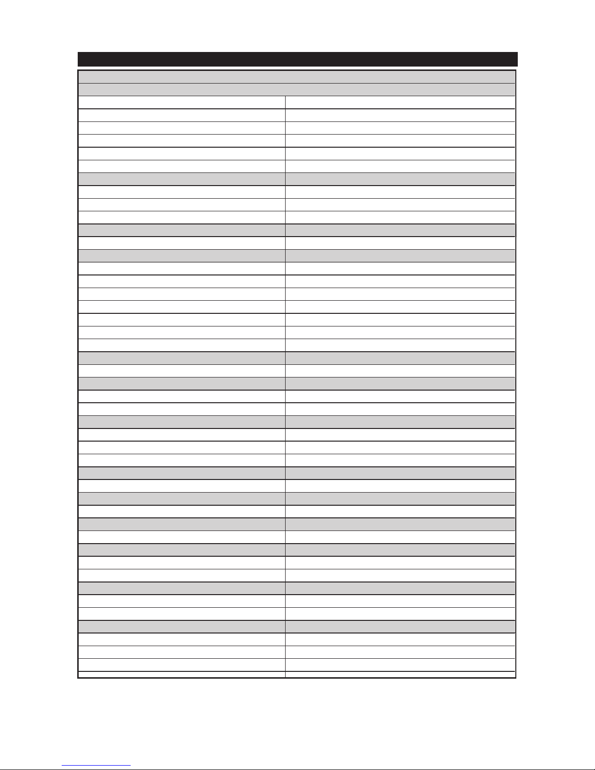
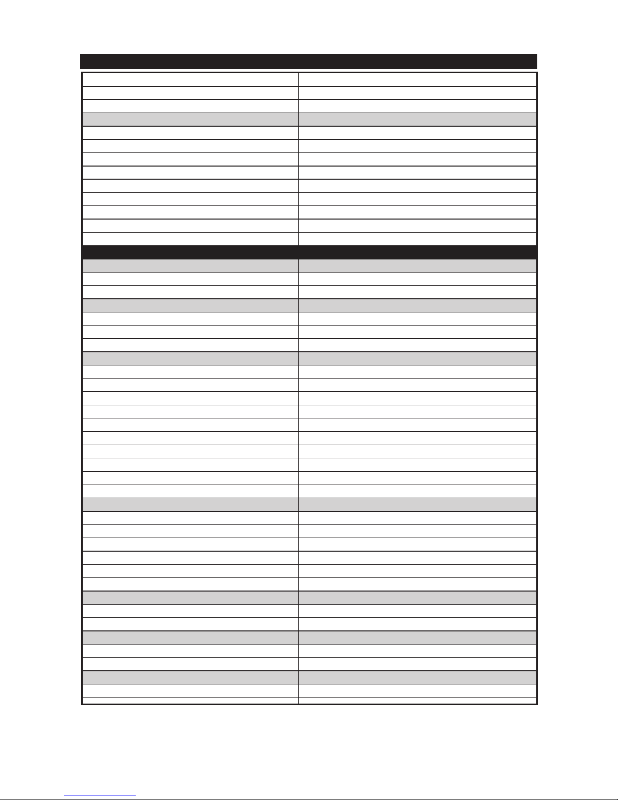
GENERAL SPECIFICATIONS
XP500 – General Specifications
Dimensions:
Overall length 2235mm
Overall width 775mm
Overall height 1410mm
Seat height 795mm
Wheelbase 1575mm
Minimum ground clearance 130mm
Weight:
Dry (without oil and fuel) 197kg
Wet (with oil and a full fuel tank) 217kg
Maximum load-except motorcycle 183kg
Performance:
Minimum turning radius 2800mm
Engine:
Engine type Liquid cooled 4-stroke, DOHC
Cylinder arrangement Forward inclined parallel 2-cylinder
Displacement 499cc
Bore x stroke 66 x 73mm
Compression ratio 10.1:1
Standard compression pressure (at sea level) 1450kPa/360r/min (14.5kgf/cm2/360r/min)
Starting system type Electric starter
Lubrication System:
Type Dry sump
Oil Type or Grade:
Engine oil SAE 10W30SE or SAE10W40SE
Chain drive oil SAE80API ”GL-4” hypoid gear oil
Oil Capacity:
Periodic oil change 2.8L
With oil filter replacement 2.9L
Total amount 3.6L
Chain Drive Oil:
Total Amount 0.7L
Radiator
Capacity (including all routes) 2.4L
Air Filter:
Type Dry element
Fuel:
Recommended fuel Regular unleaded gasoline
Fuel tank capacity 14L
Carburetor:
Type/quantity BS30/2
Manufacturer Mikuni
Spark Plug:
Type CR7E
Manufacturer NGK
Spark plug gap 0.7~0.8mm
34
Page 36
XP500 TMax Technical Orientation Guide
GENERAL SPECIFICATIONS
Transmission:
Primary reduction system Helical gear/spur gear
Primary reduction ratio 52/32x36/22(2.659)
Secondary reduction system Chain drive
Secondary reduction ratio 41/25x40/29(2.262)
Clutch type Wet multiple-disc automation
Transmission type V-Belt automatic
Chassis:
Frame type Diamond
Caster angle 28º
Trail 95mm
Tire:
Tire type Tubeless
Size(front) 120/70-14M/C 55S
Size(rear) 150/70-14M/C 66S
Manufacturer (front) Dunlop/Bridgestone
Manufacturer (rear) Dunlop/Bridgestone
Brake:
Front brake type Single disc brake
Rear brake type Single disc brake
Suspension:
Front suspension Telescopic fork
Rear suspension Swingarm
Shock Absorber:
Front fork type Coil spring/oil damper
Rear shock absorber assembly type Coil spring/gas-oil damper
Wheel Travel:
Front wheel travel 120mm
Rear wheel travel 120mm
Electrical:
Ignition system type Transistorized coil ignition (digital)
Charging system type A.C. magneto
Battery voltage/capacity 12V8Ah
Battery type GT9B-4
Headlight type Bulb type
Headlight bulb type halogen bulb
Bulbs (voltage/wattage x quantity)
Headlight 12V60W/55Wx1
Headlight 12V55Wx1
Auxiliary light 12V5Wx1
Brake /tail light 12V21W/5Wx2
Front flasher light 12V21W/5Wx2
Rear flasher light 12V21Wx2
Licence plate light 12V5Wx1
Meter light 12V1.7Wx1
Indicator light
Turn indicator light 12V3.4Wx2
35
Page 37
XP500 TMax Technical Orientation Guide
Oil level indicator light 12V1.7Wx1
High beam indicator light 12V1.7Wx1
V-belt replacement indicator light 12V1.7Wx1
Tire pressure (cold):
Loading condition A 0~90kg
Front 200kPA(2kgf/cm2)
Rear 225kPa(2.25kgf/cm2)
Loading Condition B 90~183kg
Front 225kPa(2.25kgf/cm2)
Rear 250kPa(2.5gf/cm2)
High speed riding
Front 225kPa(2.25kgf/cm2)
Rear 250kPa(2.5kgf/cm2)
Maintenance Specification
Cylinder Head
Volume 14.97~15.57cc
Max. warpage 0.03mm
Cylinder
Bore 66.00~66.01mm
Taper limit 0.05mm
Max. out of round 0.05mm
Chamshaft
Drive system Chain drive(left)
Camshaft cap inside diameter 23.000~23.021mm
Camshaft-journal-to-camshaft-cap clearance 0.020~0.054mm
Camshaft lobe dimensions
Intake-measurement A 33.252~33.352
Intake-measurement B 24.956~25.056
Intake-measurement C 8.196~8.396mm
Exhuast-measurement A 33.252~33.352
Exhaust-measurement B 24.956~25.056
Exhaust-measurement C 8.196~8.396
Valve Timing:
Intake-open (BTDC)((degree)) 25º
Intake-closed (ABDC) ((degree)) 55º
Exhaust-open (BBDC) ((degree)) 55º
Exhaust-closed (ATDC) ((degree)) 25º
Overlap angle “A” ((degree)) 50º
Max. camshaft runout 0.03mm
Timing Chain:
Model/Number of links SCR-0409 SDH/132
Tensioning system Automatic
Valve, valve seat, valve guide:
Valve clearance-intake (cold) 0.15~0.20mm
Valve clearance-exhuast (cold) 0.25~0.30mm
Valve Dimensions:
Valve head diameter A intake 24.9~25.1mm
GENERAL SPECIFICATIONS
36
Page 38
XP500 TMax Technical Orientation Guide
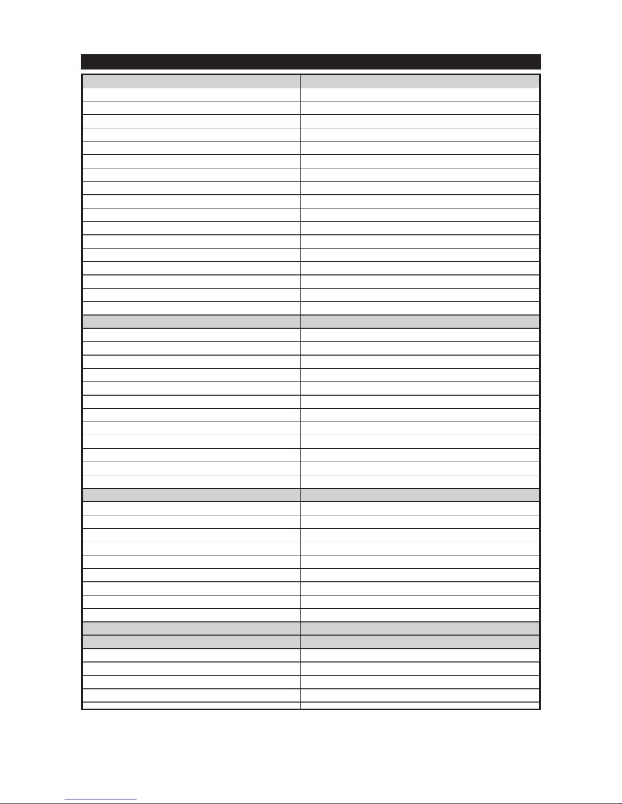
GENERAL SPECIFICATIONS
Valve head diameter A exhaust 21.9~22.1mm
Valve face width B intake 1.14~1.98mm
Valve face width B exhaust 1.14~1.98mm
Valve seat width C intake 0.9~1.1mm
Valve seat width C exhaust 0.9~1.1mm
Valve margin thickness D intake 0.6~0.8mm
Valve margin thickness D exhaust 0.6~0.8mm
Valve stem diameter-intake 3.975~3.990mm
Valve stem diameter-exhaust 3.960~3.975mm
Valve guide inside diameter-intake 4.000~4.012mm
Valve guide inside diameter-exhaust 4.000~4.012mm
Valve stem to valve guideclearance-intake 0.010~0.037mm
Valve stem to valve guideclearance-exhaust 0.025~0.052mm
Valve stem runout 0.04mm
Valve seat width-intake 0.9~1.1mm
Valve seat width-exhaust 0.9~1.1mm
Valve seat material-intake PB6
Valve seat material-exhaust V557W
Valve spring:
Free length-intake 35.59mm
Free length-exhaust 35.59mm
Spring rate-intake (K1) 18.845N/mm(1.92kgf/mm)
Spring rate-intake (K2) 24.52N/mm(2.5kgf/mm)
Spring rate-exhaust (K1) 18.845N/mm(1.92kgf/mm)
Spring rate-exhaust (K2) 24.52N/mm(2.5kgf/mm)
Installed length-intake (valve closed) 30.39mm
Installed length-exhaust (valve closed) 30.39mm
Spring tilt-intake ((degree)) 2.5º/1.6mm
Spring tilt-exhaust ((degree)) 2.5º/1.8mm
Winding direction-intake(top view) Clockwise
Winding direction-exhaust(top view) Clockwise
Piston:
Piston part number (***-11631-**) 5GJ-11631-00
Piston-to-cylinder clearance 0.020~0.045mm
<Limit> 0.15mm
Diameter D 65.965~65.980mm
Height H 9mm
Offset 0.5mm
Offset direction Intake side
Piston pin bore inside diameter 16.002~16.013mm
Piston pin outside diameter 15.991~16.000mm
Piston ring:
Top ring:
Ring type Barrel
Dimensions (B x T) 0.80x2.45mm
End gap (installed) 0.15~0.25mm
Ring side clearance 0.030~0.065mm
37
Page 39
XP500 TMax Technical Orientation Guide
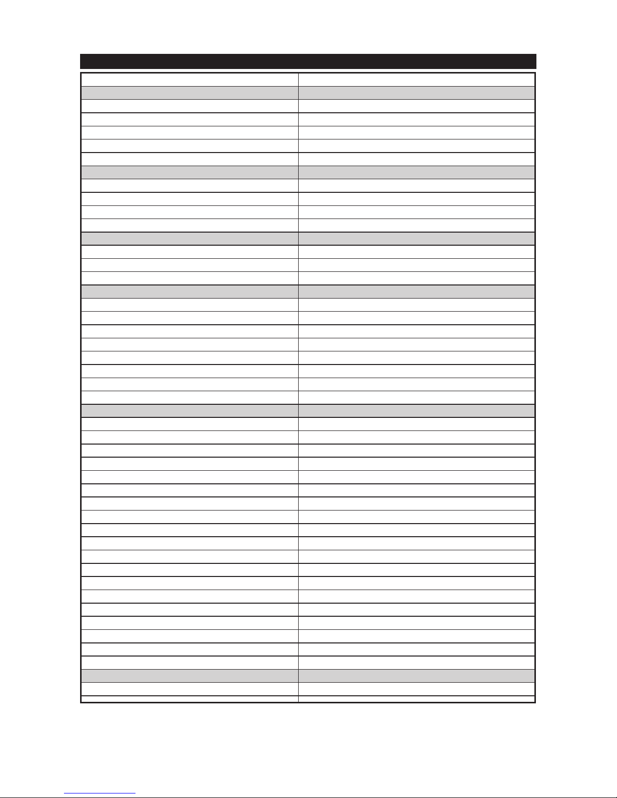
GENERAL SPECIFICATIONS
Plating/coating Chrome plated/ferox coating
2nd ring:
Ring type Plain
Dimensions (B x T) 0.8x2.5mm
End gap (installed) 0.4~0.5mm
Ring side clearance 0.020~0.055mm
Plating/coating Parkerrizing
Oil ring:
Dimensions (B x T) 1.5x2.0mm
End gap (installed) 0.10~0.35mm
Ring side clearance 0.04~0.16mm
Plating/coating Chrome plated/parkerrizing
Connecting rod:
Oil clearance (using plasti-gauge) 0.026~0.050mm
Bearing color code 1.Blue 2.Black 3.Brown 4.Green
Connecting rod length 124.45~124.55mm
Crankshaft:
Width A 50.0~50.6mm
Width B 118.55~118.60mm
Max. runout C 0.03mm
Big end side clearance D 0.160~0.262mm
Big end radial clearance E 0.026~0.050mm
Journal oil clearance (using plasti-gauge) 0.040~0.082mm
Bearing color code 1.Blue 2.Black 3.Brown 4.Green
Ballancer drive method Piston
Clutch:
Friction plate thickness 2.75~3.05mm
Plate quantity 5pcs
Wear limit 2.65mm
Friction plate thickness 1.8~2.0mm
Plate quantity 2pcs
Wear limit 1.7mm
Clutch plate thickness 1.3~1.5mm
Plate quantity 4pcs
Max. warpage 0.1mm
Clutch spring free length 25.9mm
Spring quantity 6pcs
Minimum length 25.4mm
Clutch spring height 4.7mm
Spring quantity 1pcs
Minimum height 4.4mm
Clutch spring height 3.3mm
Spring quantity 6pcs
Minimum height 2.9mm
Clutch release method Automatic
Carburetor:
ID mark 5GJ1 00
38
Page 40
XP500 TMax Technical Orientation Guide
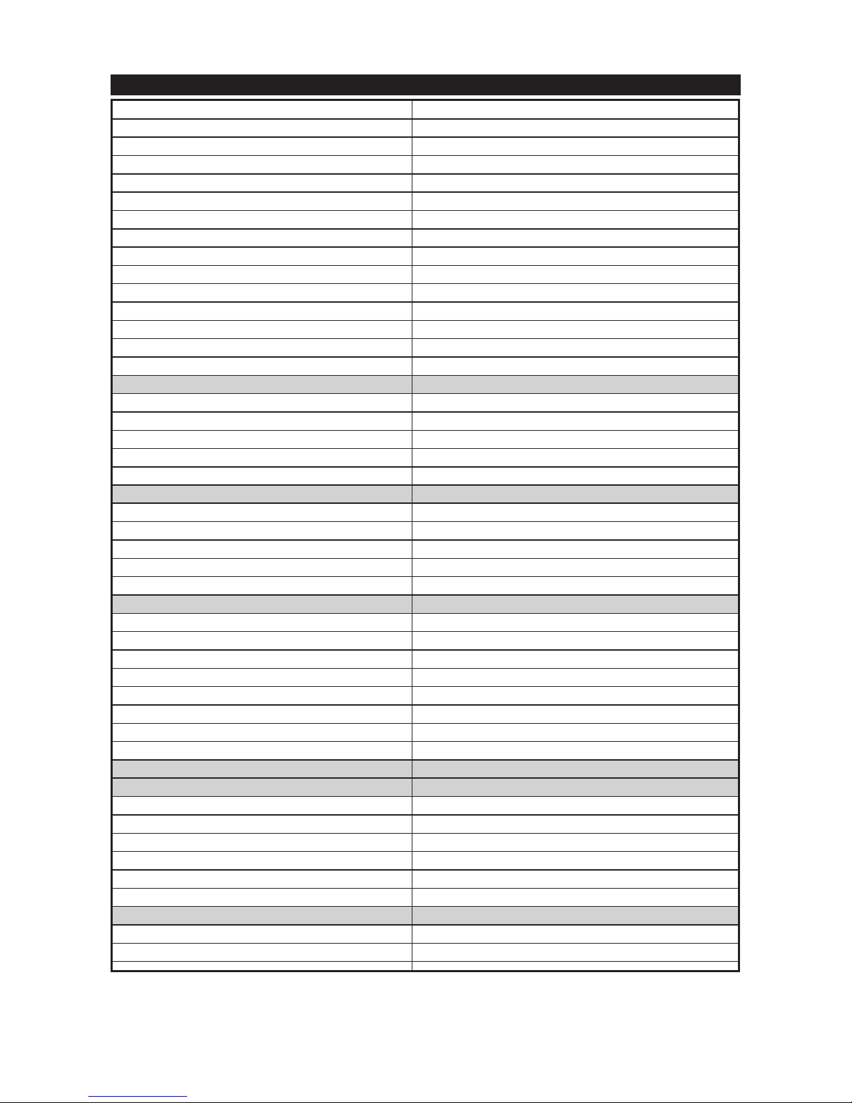
Fuel level (using special tool) 29.5~30.5mm
Main jet #102.5
Main air jet #100
Jet needle 4DK4-3/5
Needle jet O-0M (#893)
Pilot air jet 1 #85
Pilot air jet 2 #170
Pilot outlet 0.8
Pilot jet #22.5
Bypass 1 0.8
Bypass 2 0.8
Bypass 3 0.8
Pilot screw turns out 2
Valve seat size 1
Throttle valve size #117.5
Idling condition:
Engine idle speed 1150~1200r/min
CO% with AIS blocked 3%
Intake vacuum 35kPa(263mmHg)
Water temparature ((degreeC)) 85~100ºc
Oil temparature ((degree C)) 70ºc
Fuel pump:
Pump type Electrical
Model/manufacturer 3LN/MITSUBISHI
Consumption amperage (max.) 0.8A
Output pressure 8.3~12.3kPa(0.08~0.12kgf/cm2)
Oil filter type: Wire mesh
Oil pump:
Oil pump type Trochoid
Inner rotor to outer rotor tip clearance 0.04~0.12mm
Outer rotor to pump housing clearance 0.045~0.085mm
Housing and rotor clearance 0.11~0.23mm
Bypass valve opening pressure 80~120kPa(0.8~1.2kgf/cm2)
Relief valve operating pressure 450~550kPa(4.5~5.5kgf/cm2)
Oil pressure (hot) 150kPa/1200r/min(1.5kgf/cm2/1200r/min)
Pressure check location MAIN GALLERY
Cooling system:
Radiator core:
Width 330mm
Height 138mm
Depth 24mm
Radiator cap opening pressure 107.9~137.3kPa(1.08~1.37kgf/cm2)
Coolant reservoir capacity 0.6L
<from low to full level> 0.25L
Water pump:
Water pump type Single suction centrifugal pump
Reduction ratio 23/19(1.210)
GENERAL SPECIFICATIONS
39
Page 41
XP500 TMax Technical Orientation Guide
GENERAL SPECIFICATIONS
Steering:
Steering bearing type Angular bearing
Lock to lock angle (left)((degree)) 38.5º
Lock to lock angle (Right)((degree)) 38.5º
Front suspension:
Front fork travel 120mm
Fork spring free length 428.5mm
Installed length 419.5mm
Collar length 129.6mm
Spring rate (K 1) 11.8N/mm(1.2kgf/mm)
Spring rate (K 2) 15.7N/mm(1.6kgf/mm)
Spring rate (K 3) 19.6N/mm(2kgf/mm)
Spring stroke (K 1) 0~19mm
Spring stroke (K 2) 19~83mm
Spring stroke (K 3) 83~120mm
Optional spring available No
Oil Quantity 402cc
Oil Level 135mm
Recommended oil Fork oil 7.5W or equivalent
Inner tube outer diameter 38mm
Rear suspension:
Rear shock absorber assembly travel 44.5mm
Spring free length 190mm
Installed length 180mm
Spring rate (K 1) 226N/mm(23.05kgf/mm)
Spring rate (K 2) 294N/mm(29.98kgf/mm)
Spring stroke (K 1) 0~30mm
Spring stroke (K 2) 30.0~44.5mm
Optional spring available No
Enclosed gas/air pressure(STD) 4900kPa(49kgf/cm2)
Swingarm:
Free play limit(at the end of the swingarm)-radial 1mm
Free play limit(at the end of the swingarm)-axial 1mm
Front wheel:
Wheel type Cast wheel
Rim size 14M/C x MT3.50
Rim material Aluminum
Max. radial wheel runout 1mm
Max. lateral wheel runout 0.5mm
Rear wheel:
Wheel type Cast wheel
Rim size 14M/C x MT4.50
Rim material Aluminum
Max. radial wheel runout 1mm
Max. lateral wheel runout 0.5mm
Front disc brake:
Disc brake type Single
40
Page 42
XP500 TMax Technical Orientation Guide
Disc outside diameter x thickness 282x5mm
Max. deflection 0.15mm
Brake pad lining thickness-inner 6mm
<Limit> 0.8mm
Brake pad lining thickness-outer 6mm
<Limit> 0.8mm
Master cylinder inside diameter 14mm
Caliper cylinder inside diameter 30.16mm
Caliper cylinder inside diameter 33.34mm
Recommended fluid Dot 4
Rear disc brake:
Disc brake type Single
Disc outside diameter x thickness 267x5mm
Max. deflection 0.15mm
Brake pad lining thickness-inner 8.3mm
<Limit> 0.8mm
Brake pad lining thickness-outer 8.3mm
<Limit> 0.8mm
Master cylinder inside diameter 12.7mm
Caliper cylinder inside diameter 38.1mm
Recommended fluid Dot 4
Brake lever and brake pedal:
Brake lever free play (pivot) 1.8~2.6mm
Brake lever free play (lever end) 6.7~14.1mm
Throttle grip free play 3~5mm
Ignition system:
Ignition timing (B.T.D.C.)((degree)) 10º/1200r/min
Advancer type Digital
Transistorized coil ignition:
Pickup coil resistance ((ohm)) 210Ω+-10%Gy-B
T.C.I. unit model/manufacturer J4T120/MITSUBISHI
Ignition coil:
Model/manufacturer JO313/DENSO
Primary coil resistance ((ohm)) 2.2Ω+-15%
Secondary coil resistance((k ohm)) 15KΩ+-20%
Spark plug cap:
Material Resin
Resistance ((k ohm)) 10KΩ
A.C. magneto:
Model/manufacturer F4T373/MITSUBISHI
Standard output 14V310W5000r/min
Stator coil resistance ((ohm)) 0.375Ω+-10%W-W
Rectifier/regulator:
Regulator type Semi conductor-short circuit
Model/manufacturer SH650A-12/SHINDENGEN
No load regulated voltage(DC) 14.5<+->0.4V
Rectifier capacity (DC) 18A
GENERAL SPECIFICATIONS
41
Page 43
XP500 TMax Technical Orientation Guide
Withstand voltage 200V
Battery:
Specific gravity 1.32
Electric starting system:
System type Constant mesh
Starter motor:
Model/manufacturer SM-13/YAMAHA
Power output 07kW
Armature coil resistance ((ohm)) 0.0015~0.0025Ω
Brush overall length 12mm
<Limit> 4mm
Brush spring force 7.65~10.01N(780~1021gf)
Commutator diameter 28mm
<Limit> 27mm
Mica undercut (depth) 0.7mm
Starter relay:
Model/manufacturer MS5F-561/JIDECO
Amperage 180A
Coil resistance ((ohm)) 4.4Ω+-5%
Horn: Horn type Plane
Quantity 2pcs
Model/manufacturer YF-12/NIKKO
Max. amperage 3A
Turn signal/hazard relay:
Relay type Full transistor
Model/manufacturer FE246BH/DENSO
Self cancelling device built-in No
Turn signal blinking frequency 75~95cyl/min
Wattage 21Wx2+3.4W
Fuel gauge:
Model/manufacturer 5GJ/NIPPON SEIKI
Sender unit resistance-full ((ohm)) 4~10Ω
Sender unit resistance-empty ((ohm)) 90~100Ω
Circuit breaker:
Circuit breaker type Fuse
Amperage for fuses:
Main fuse 30A
Headlight fuse 15A
Signaling system fuse 15A
Ignition fuse 10A
Radiator fan fuse 15A
Back up fuse 10A
Reserve fuse 30A
Reserve fuse 15A
Reserve fuse 10A
Thermo-unit:
Model/manufacturer 46X/NIPPON SEIKI
GENERAL SPECIFICATIONS
42
Page 44
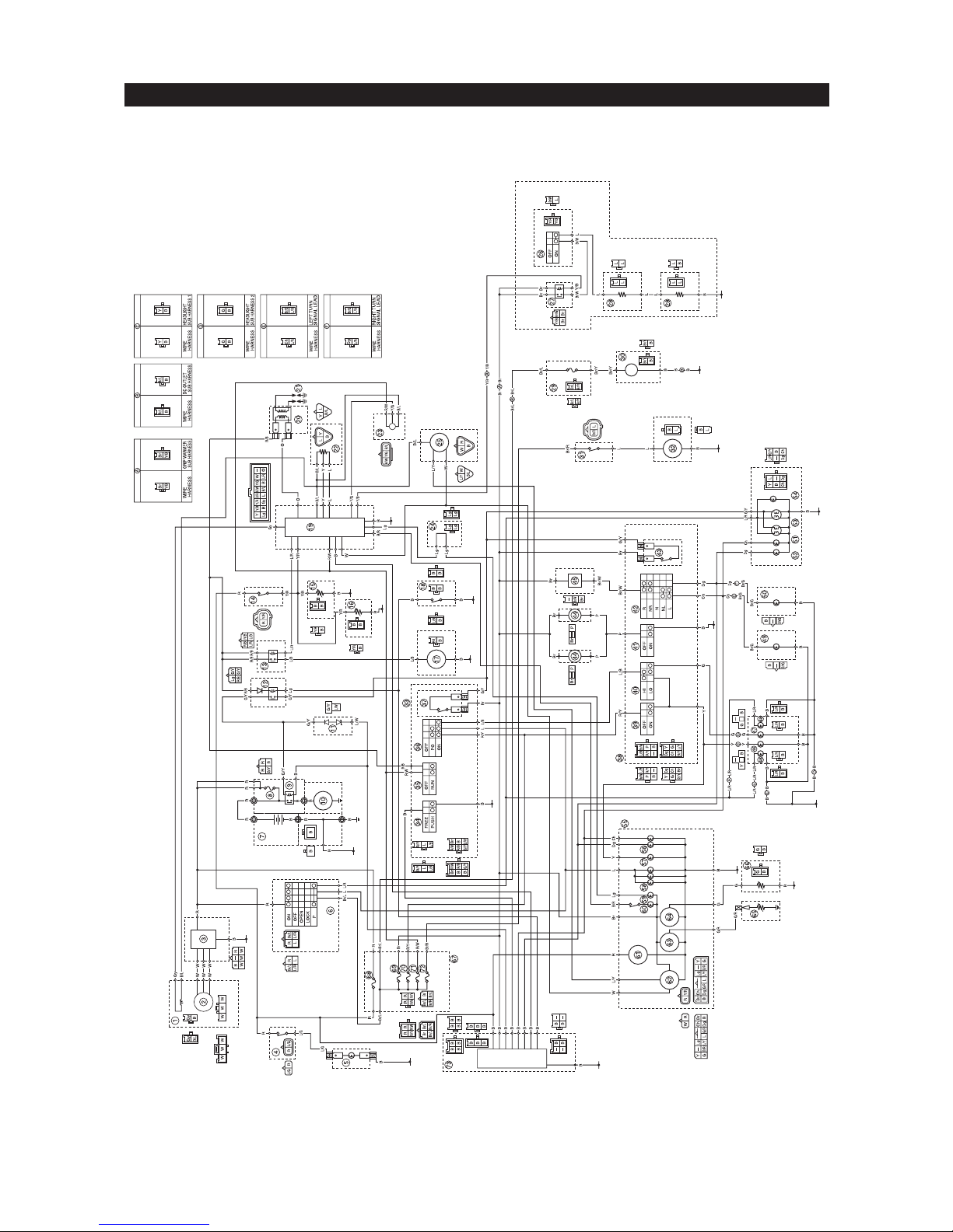
WIRING DIAGRAM
XP500 TMax Technical Orientation Guide
44
Page 45
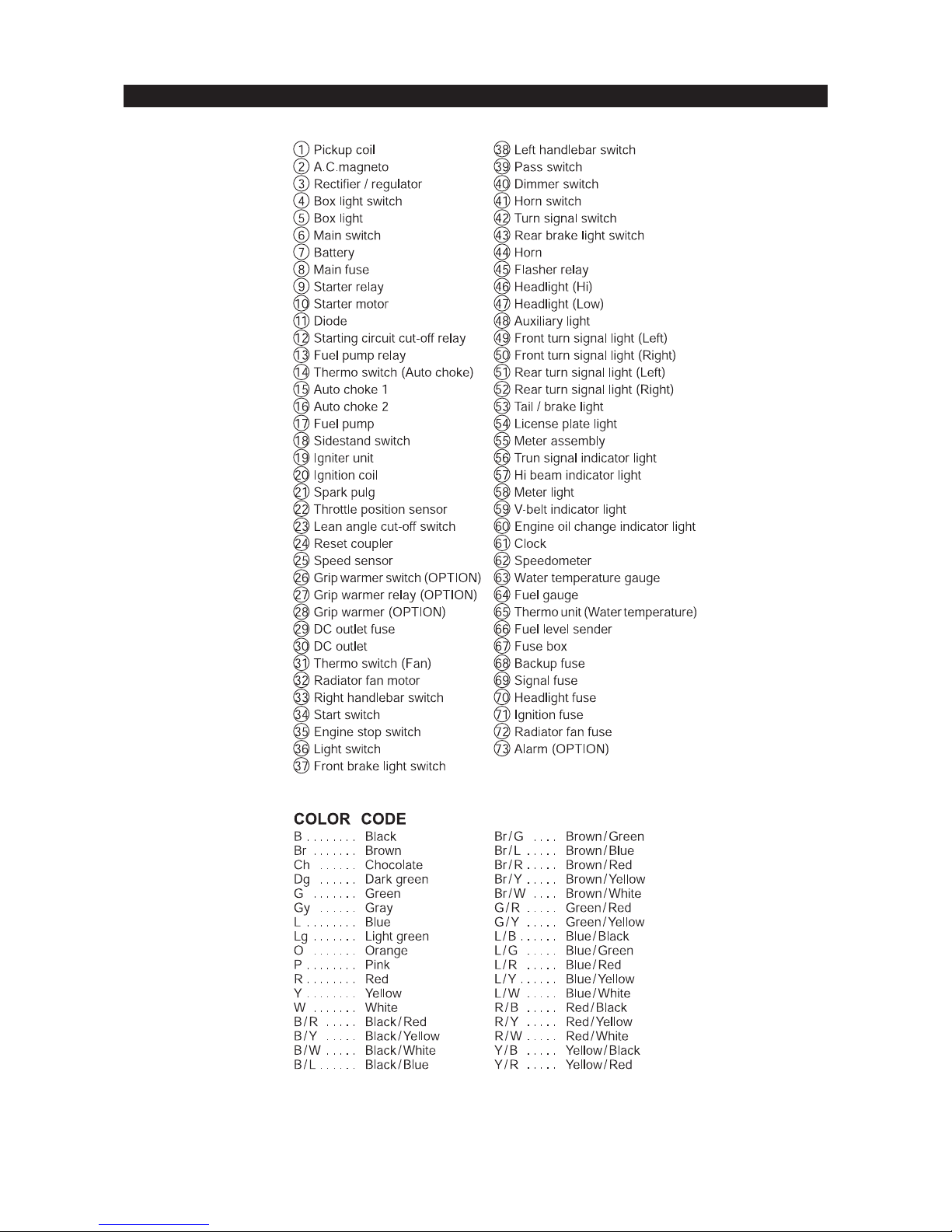
WIRING DIAGRAM
XP500 TMax Technical Orientation Guide
45
 Loading...