

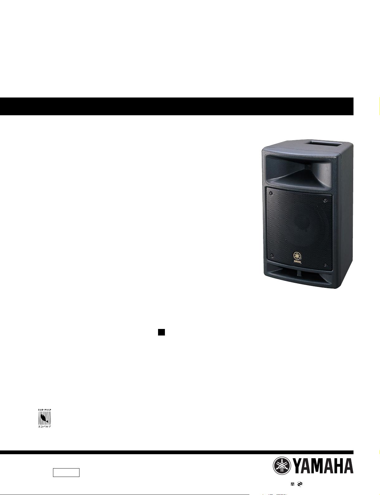
POWERED SPEAKER
MSR100/SMS100
SERVICE MANUAL
このサービスマニュアルはエコパルプ
(ECF:無塩素系漂白パルプ)を使用しています。
This document is printed on chlorine free (ECF) paper.
MSR100
CONTENTS
SPECIFICATIONS ................................................. 3
PERFORMANCE GRAPH .......................................... 4
PANEL LAYOUT ...................................... 4
CIRCUIT BOARD LAYOUT ................. 5
DIMENSIONS ............................................................ 5
LEVEL DIAGRAM ................................ 6
DISASSEMBLY PROCEDURE .............................. 7
IC BLOCK DIAGRAM ................................... 12
CIRCUIT BOARDS ......................................... 12
INSPECTIONS ............................................................ 17
BLOCK DIAGRAM
CIRCUIT DIAGRAM
PARTS LIST
(目次)
(総合仕様)
(特性図)
(パネルレイアウト)
(ユニットレイアウト)
(寸法図)
(レベルダイアグラム)
(分解手順)
(ICブロック図)
(シート基板図)
(検査)
(ブロックダイアグラム)
(回路図)
011662
PA
20021201-56000
0.166K-7304 Printed in Japan ’02.11
HAMAMATSU, JAPAN
MSR100/SMS100
This manual has been provided for the use of authorized Yamaha Retailers and their service personnel. It has been assumed
that basic service procedures inherent to the industry, and more specifically Yamaha Products, are already known and understood by the users, and have therefore not been restated.
WARNING : Failure to follow appropriate service and safety procedures when servicing this product may result in per-
IMPORTANT : This presentation or sale of this manual to any individual or firm does not constitute authorization certifi-
The data provided is belived to be accurate and applicable to the unit(s) indicated on the cover. The research engineering, and
service departments of Yamaha are continually striving to improve Yamaha products. Modifications are, therefore, inevitable
and changes in specification are subject to change without notice or obligation to retrofit. Should any discrepancy appear to
exist, please contact the distributor’s Service Division.
WARNING : Static discharges can destroy expensive components. Discharge any static electricity your body may have
IMPORTANT : Turn the unit OFF during disassembly and parts replacement. Recheck all work before you apply power
IMPOR TANT NOTICE
sonal injury, destruction of expensive components and failure of the product to perform as specified. For
these reasons, we advise all Yamaha product owners that all service required should be performed by an
authorized Yamaha Retailer or the appointed service representative.
cation, recognition of any applicable technical capabilities, or establish a principal-agent relationship of
any form.
accumulated by grounding yourself to the ground bus in the unit (heavy gauge black wires connect to
this bus.)
to the unit.
WARNING: CHEMICAL CONTENT NOTICE!
The solder used in the production of this product contains LEAD. In addition, other electrical/electronic and/or plastic (Where
applicable) components may also contain traces of chemicals found by the California Health and Welfare Agency (and possibly
other entities) to cause cancer and/or birth defects or other reproductive harm.
DO NOT PLACE SOLDER, ELECTRICAL/ELECTRONIC OR PLASTIC COMPONENTS IN YOUR MOUTH FOR ANY REASON WHAT
SO EVER!
Avoid prolonged, unprotected contact between solder and your skin! When soldering, do not inhale solder fumes or expose
eyes to solder/flux vapor!
If you come in contact with solder or components located inside the enclosure of this product, wash your hands before handling
food.
WARNING: THIS APPARATUS MUST BE EARTHED
IMPORTANT
THE WIRES IN THIS MAINS LEAD ARE COLOURED IN
ACCORDANCE WITH THE FOLLOWING CODE:
GREEN-AND-YELLOW : EARTH
BLUE : NEUTRAL
BROWN : LIVE
As the colours of the wires in the mains lead of this apparatus may
not correspond with the coloured markings identifying the terminals in
your plug, proceed as follows:
The wire which is coloured GREEN and YELLOW must be
connected to the terminal in the plug which is marked by the letter E
or by the safety earth symbol or coloured GREEN and YELLOW.
The wire which is coloured BLUE must be connected to the terminal
which is marked with the letter N or coloured BLACK.
The wire which is coloured BROWN must be connected to the
terminal which is marked with the letter L or coloured RED.
* This applies only to products distributed by YAMAHA KEMBLE
MUSIC (U.K.) LTD.
WARNING
Components having special characteristics are marked and must be replaced with parts having specification equal to those
originally installed.
印の商品は、安全を維持するために重要な部品です。交換する場合は、安全のために必ず指定の部品をご使用下さい。
2

MSR100/SMS100
、
、
SPECIFICATIONS
General specifications
Type
2way Bass Reflex Powered Speaker
Speaker Unit
LF: 200 mm Cone
HF: 25.4 mm Compression Driver
Frequency Range..................55 Hz—20 kHz (–10 dB)
Cross Over Frequency..........4 kHz
Maximum Output Level.........112 dB (1 m)
Dimension (W×H×D).............275 × 455.5 × 255 mm
Weight..................................11 kg
Color.....................................Black (Approximate Munsell
Value 5 PB2/1)
Accessories..........................Power supply cord 2.5 m (AC
Inlet type)
Option..................................BWS50-190/260/320,
BCS251, BBS251
Amp. Unit
Max Power...........................100W at 1 kHz, THD=1%,
RL=6 Ω
Input Sensitivity....................INPUT 1: –50 dB* (MIC),
+4 dB* (LINE)
INPUT 2, 3: –10 dB*
Input Impedance..................INPUT 1, 2, 3: 10 k Ω
Output Sensitivity.................LINK OUT: –10 dB*
Output Impedance...............LINK OUT: 10 k Ω
Controls
LEVEL Control...............INPUT 1, 2, 3, MASTER
EQ Control......................LOW: ±3 dB at 60 Hz
HIGH: ±6 dB at 10 kHz
POWER Switch..............ON/OFF
Connectors
INPUT 1..........................XLR-3-31 (balanced)
INPUT 2, 3......................Phone (unbalanced)
LINK OUT.......................Phone (unbalanced)
Indicator
POWER Indicator............Green LED
CLIP Indicator.................Red LED
Power Requirement
USA and Canada...........AC 120 V, 60 Hz
Europe............................AC 230 V, 50 Hz
Australia.........................AC 240 V, 50 Hz
Korea
.................................A
Power Consumption.............70 W
C 220 V, 60 Hz
総合仕様
●総合仕様
形式
2ウェイバスレフ型パワードスピーカー
スピーカーユニット
LF:200mmコーン
HF:25.4mmコンプレッションドライバー
再生周波数帯域....................55Hz〜20kHz(-10dB)
クロスオーバー周波数.........4kHz
最大出力音圧レベル............112dB(軸上1m)
最大外形寸法
質量......................................11kg
色.........................................黒(近似マンセル値
付属品..................................電源コード(AC インレッ
オプション...........................BWS50-190/260/320、
(W×H×D)
●アンプ部
定格最大出力.......................100W at 1kHz、THD=1%
入力感度..............................INPUT1: -50dB*(MIC)
入力インピーダンス.............INPUT1、2、3:10kΩ
出力感度...............................LINKOUT:-10dB*
出力インピーダンス.............LINKOUT:10kΩ
コントロール
LEVELコントロール.........INPUT1、2、3、MASTER
EQコントロール...............LOW:±3dBat60Hz
POWERスイッチ..............ON/OFF
コネクター
INPUT1.............................XLR-3-31(バランス型)
INPUT2、3.......................フォーン(アンバランス型)
LINKOUT.........................フォーン(アンバランス型)
インジケーター
POWERインジケーター...緑色発光LED
CLIPインジケーター.........赤色発光LED
電源.......................................AC100V、50/60Hz
消費電力................................65W
*0dB=0.775V
.....275 ×455.5 ×255mm
5PB2/1)
ト型、2.5m)
BCS251、BBS251
RL=6Ω
+4dB*(LINE)
INPUT 2、3: -10dB*
HIGH:±6dBat10kHz
* 0 dB=0.775 V
For European Model
Purchaser/User Information specified in EN55103-1 and
EN55103-2.
Inrush Current: 10A
Conformed Environment: E1, E2, E3 and E4
3
MSR100/SMS100
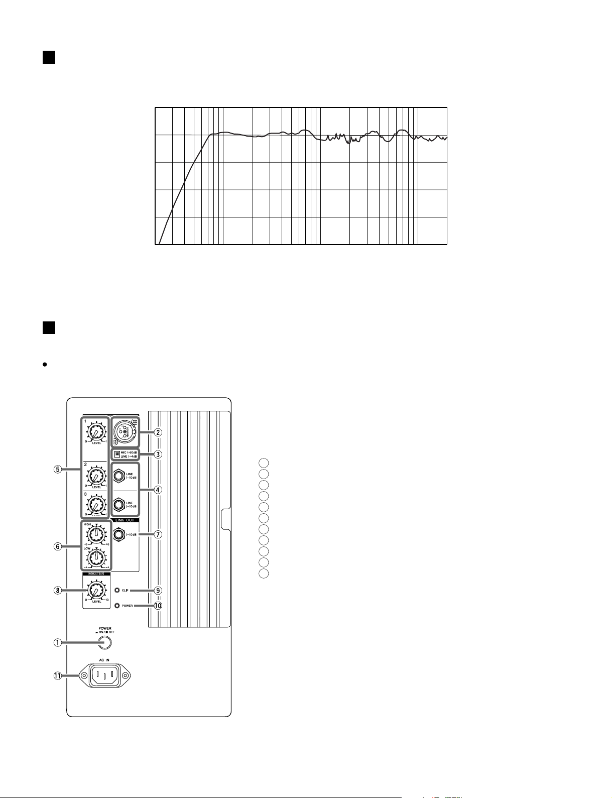
PERFORMANCE GRAPH
+10
0
-10
-20
RESPONSE (dB)
-30
-40
20
PANEL LAYOUT
(パネルレイアウト)
(特性図)
10k1k100
FREQUENCY (Hz)
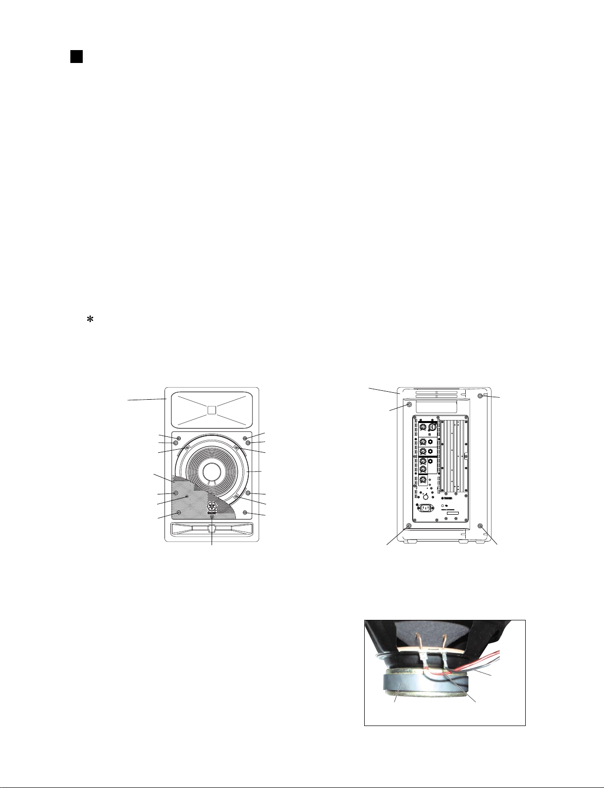
Rear Panel
(リアパネル)
1
[POWER] Switch
2
[INPUT1] Connector
3
Sensitivity Switch
4
[INPUT2] and [INPUT3] Connectors
5
[LEVEL] Controls
6
[EQ] Controls
7
[LINK OUT] Connector
8
[MASTER LEVEL] Control
9
[CLIP] Indicator
10
[POWER] Indicator
11
[AC IN] Connector
(電源スイッチ)
(入力1端子)
(感度切り換えスイッチ)
(入力2端子、入力3端子)
(音量コントロール)
(音質コントロール)
(出力端子)
(全体音量コントロール)
(クリップインジケーター)
(電源インジケーター)
(電源入力端子)
4
MSR100/SMS100
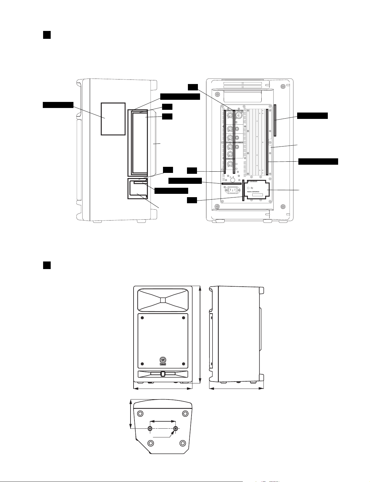
CIRCUIT BOARD LAYOUT
〈
Right side view
NETWORK
(ユニットレイアウト)
〉 〈
IN
POWER AMPLIFIER
IN
EQ
Power amplifier assembly
(パワーアンプAss'y)
AC
EQ
POWER SWITCH
POWER SWITCH
AC
Power transformer
(電源トランス)
1
010
LEVEL
2
0
LEVEL
3
0
LEVEL
EQ
HIGH
LOW
MASTERMASTER
0
LEVEL
POWER
ON/OFF
Rear view
INPUT
2
NEUTRIK
3
1
MIC(-50dB)
LINE(+4dB)
LINE
(-10dB)
10
LINE
(-10dB)
10
LINK OUT
(-10dB)
+6-6
+3-3
CLIP
10
POWER
POWERED SPEAKER
AC IN
MODEL MSR100
PS
E
100V 65W 50/60HzÅ`
MADE IN CHINA
SER.NO.
******
〉
NETWORK
Power amplifier assembly
(パワーアンプAss'y)
POWER AMPLIFIER
Power transformer
(電源トランス)
DIMENSIONS
(寸法図)
137
455.5
275 255
120
2-M8x25
Units: mm
(単位 )
5
6
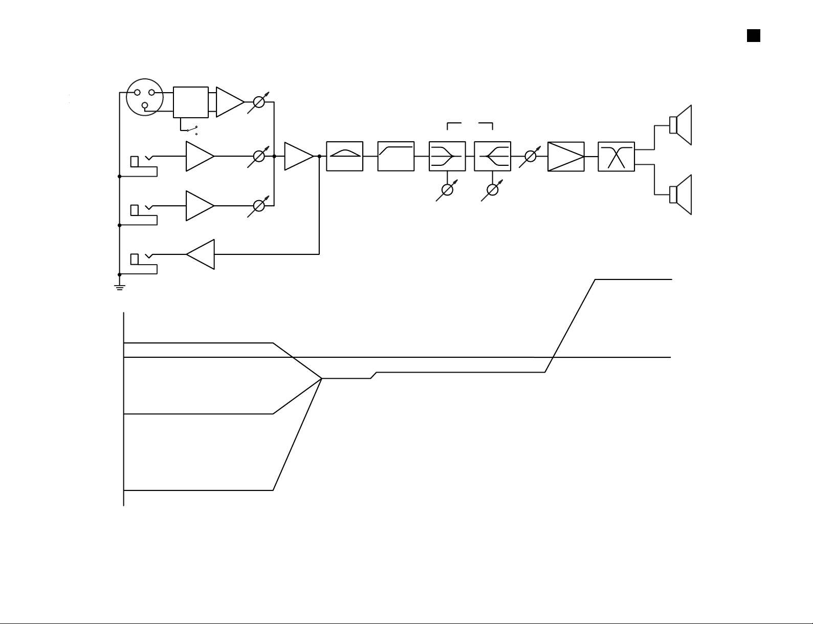
OUTPUT
(ー10dBu)
INPUT1
INPUT2, 3
(LINE)
0dBu
+4dBu
-10dBu
-50dBu
-4.7dBu
-2.2dBu
+29.9dBu (SP OUT)
INPUT1
(MIC)
INPUT3
(ー10dBu)
INPUT2
(ー10dBu)
INPUT1
(ー50dBu/+4dBu)
MIC
LINE
LF
HF
6Ω 100W
NW
MASTER
LEVEL
EQ
HIGHLOW
LOW
CUT
LOW
BOOST
P.AMP
MSR100/SMS100
LEVEL DIAGRAM
(レベルダイアグラム)
MSR100/SMS100
DISASSEMBLY PROCEDURE
1. Front Grille Assembly
(Time required: About 1 minute)
1-1 Remove the f our (4) screws marked [100A]. The front
grille assembly can then be removed. (Fig.1)
2. Speaker LF (Woofer)
(Time required: About 2 minutes)
2-1 Remove the front grille assembly. (See procedure 1.)
2-2 Remove the four (4) screws marked [80]. The
speaker LF (Woofer) can then be removed. (Fig.1)
2-3 Remove the wire LF (red/black) installed to the
speaker LF (Woofer). (Photo.1)
3. Front Cabinet Unit and Rear Cabinet Unit
(Time required: About 3 minutes)
3-1 Remove the front grille assembly. (See procedure 1.)
3-2 Remove the speaker LF (Woof er). (See procedure 2.)
3-3 Remove the five (5) screws marked [50A] and the f our
(4) screws marked [50B]. The front cabinet unit and
the rear cabinet unit can then be divided. (Fig.1, 2)
Take care not to damage the speaker HF
(Tweeter) terminal when opening the front
cabinet unit and the rear cabinet unit.
(分解手順)
1. フロントグリルAss'y(所要時間:約 1 分)
1-1 [100A]のネジ4 本を外して、フロントグリル Ass'y
を外します。(図1)
2. スピーカLF(ウーファー)(所要時間:約 2 分)
2-1 フロントグリル Ass'y を外します。(1 項参照)
2-2 [80]のネジ4本を外して、スピーカLF(ウーファー)
を外します。(図1)
2-3 スピーカLF( ウーファー)に取り付けられている束
線 LF(赤/黒)を外します。(写真 1)
3. フロントキャビネット部、
リアキャビネット部
3-1 フロントグリル Ass'y を外します。(1 項参照)
3-2 スピーカ LF(ウーファー)を外します。(2 項参照)
3-3 [50A]のネジ5本と[50B]のネジ4 本を外して、フロ
ントキャビネット部とリアキャビネット部を別けま
す。(図 1,2)
※ フロントキャビネット部とリアキャビネット部を開
きすぎて、スピーカHF(ツィーター)端子を傷めな
いように注意して下さい。
(所要時間:約 3 分)
〈
Front view
Front cabinet unit
(フロントキャビネット部)
[100A]
[50A]
[80]
Front grille assembly
(フロントグリルAss'y)
[50A]
[80]
[100A]
[50A]: Bind Head Tapping Screw-A
5.0X35 BL (AAX42210)
[80]: Bind Head Tapping Screw-B
4.0X18 BL (AAX42230)
[100A]: Bind Head Tapping Screw-B
4.0X10 BL (AAX12100)
〈
Rear view
〉
〉
Rear cabinet unit
[50A]
Fig.1
(+バインドAタイト)
(+バインドBタイト)
(+バインドBタイト)
(図1)
(リアキャビネット部)
[100A]
[50A]
[80]
Speaker LF (Woofer)
(スピーカLF(ウーファー))
[50A]
[80]
[100A]
[50B]
INPUT
1
2
NEUTRIK
3
1
010
LEVEL
MIC(-50dB)
LINE(+4dB)
2
LINE
(-10dB)
10
0
LEVEL
3
LINE
(-10dB)
10
0
LEVEL
EQ
LINK OUT
HIGH
(-10dB)
+6-6
LOW
+3-3
MASTERMASTER
CLIP
10
0
LEVEL
POWER
POWER
ON/OFF
POWERED SPEAKER
AC IN
MODEL MSR100
PS
E
100V 65W 50/60HzÅ`
MADE IN CHINA
SER.NO.
******
[50B]
[50B]: Bind Head Tapping Screw-A
5.0X35 BL (AAX42210)
(図2)
Fig.2
[50B]
[50B]
(+バインドAタイト)
Speaker LF (Woofer)
(スピーカLF(ウーファー))
Photo.1 (写真1)
Wire LF (Black)
(束線LF(黒))
Wire LF (Red)
(束線LF(赤))
7
MSR100/SMS100
))
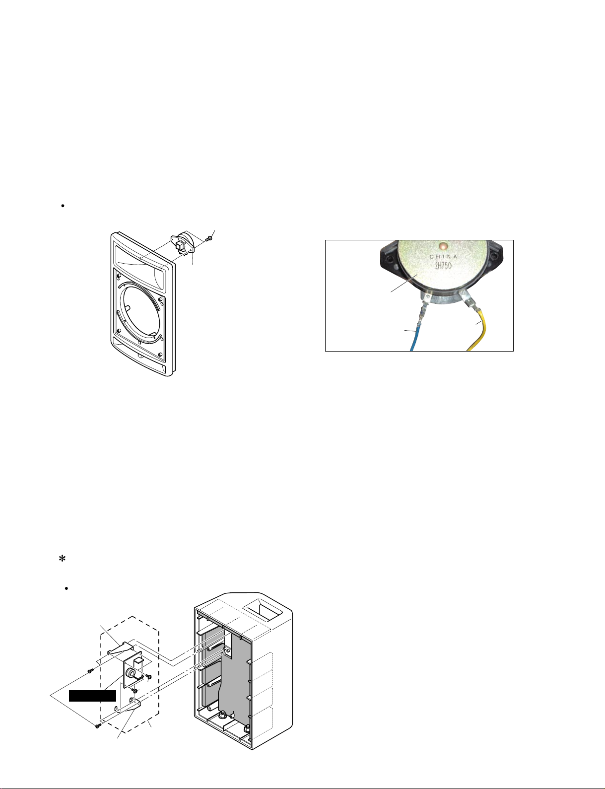
4. Speaker HF (Tweeter)
(Time required: About 3 minutes)
4-1 Remove the front grille assembly. (See procedure 1.)
4-2 Divide the front cabinet unit and the rear cabinet
unit. (See procedure 3.)
4-3 Remove the wire HF (yellow/blue) installed to the
speaker HF (Tweeter). (Photo.2)
4-4 Remove the two (2) screws mark ed [46]. The speak er
HF (Tweeter) can then be removed from the front
cabinet unit. (Fig.3)
Front Cabinet Unit
(フロントキャビネット部)
[46]
Speaker HF (Tweeter)
(スピーカHF(ツィーター
4. スピーカHF(ツィーター)(所要時間:約 3 分)
4-1 フロントグリル Ass'y を外します。(1 項参照)
4-2 フロントキャビネット部とリアキャビネット部を別
けます。(3項参照)
4-3 スピーカ HF(ツィーター)に取り付けられている束
線 HF(黄/青)を外します。(写真 2)
4-4 [46]のネジ2本を外して、フロントキャビネット部か
らスピーカHF(ツィーター)を外します。(図 3)
Speaker HF (Tweeter)
(スピーカHF(ツィーター))
Photo.2
Wire HF (Yellow)
(束線HF(黄))
(写真2)
Wire HF (Blue)
(束線HF(青))
[46]: Bind Head Tapping Screw-B 4.0X20 BL (AAX42200)
(+バインドBタイト)
Fig.3
(図3)
5. Network Assembly and NETW ORK Circuit Board
5-1 Remove the front grille assembly. (See procedure 1.)
5-2 Divide the front cabinet unit and the rear cabinet
unit. (See procedure 3.)
5-3 Remove the four (4) screws marked [10e]. The
network assembly can then be removed from the
rear cabinet unit. (Fig.4)
5-4 Remove the four (4) screws marked [N40]. The
network holders C and D can then be removed from
the NETWORK circuit board. (Fig.4)
Remove the P1, P2 connector assembly soldered
to the NETWORK circuit board.
Rear Cabinet Unit
(リアキャビネット部)
Network holder D
(ネットワーク固定金具D)
(Time required: About 4 minutes)
5. ネットワークAss'y、ネットワークシート
(所要時間:約4 分)
5-1 フロントグリル Ass'y を外します。(1 項参照)
5-2 フロントキャビネット部とリアキャビネット部を別
けます。(3項参照)
5-3 [10e]のネジ4本を外して、リアキャビネット部から
ネットワーク Ass'y を外します。(図 4)
5-4 [N40]のネジ4 本を外して、ネットワークシートか
らネットワーク固定金具 C、D を外します。(図4)
※ネットワークシートに取り付けられている線材 P1、
P2の半田を外せば、シートが外せます。
8
[10e]
NETWORK
Network holder C
(ネットワーク固定金具C)
[N40]
Network assembly
(ネットワークAss'y)
[10e]: Bind Head Tapping Screw-B 3.0X10 BL (AAX10840)
[N40]: Cup Screw-B PW3.0X8 Y (AAX43390)
(図4)
Fig.4
(+カップネジBタイト)
(+バイントBタイト)
MSR100/SMS100
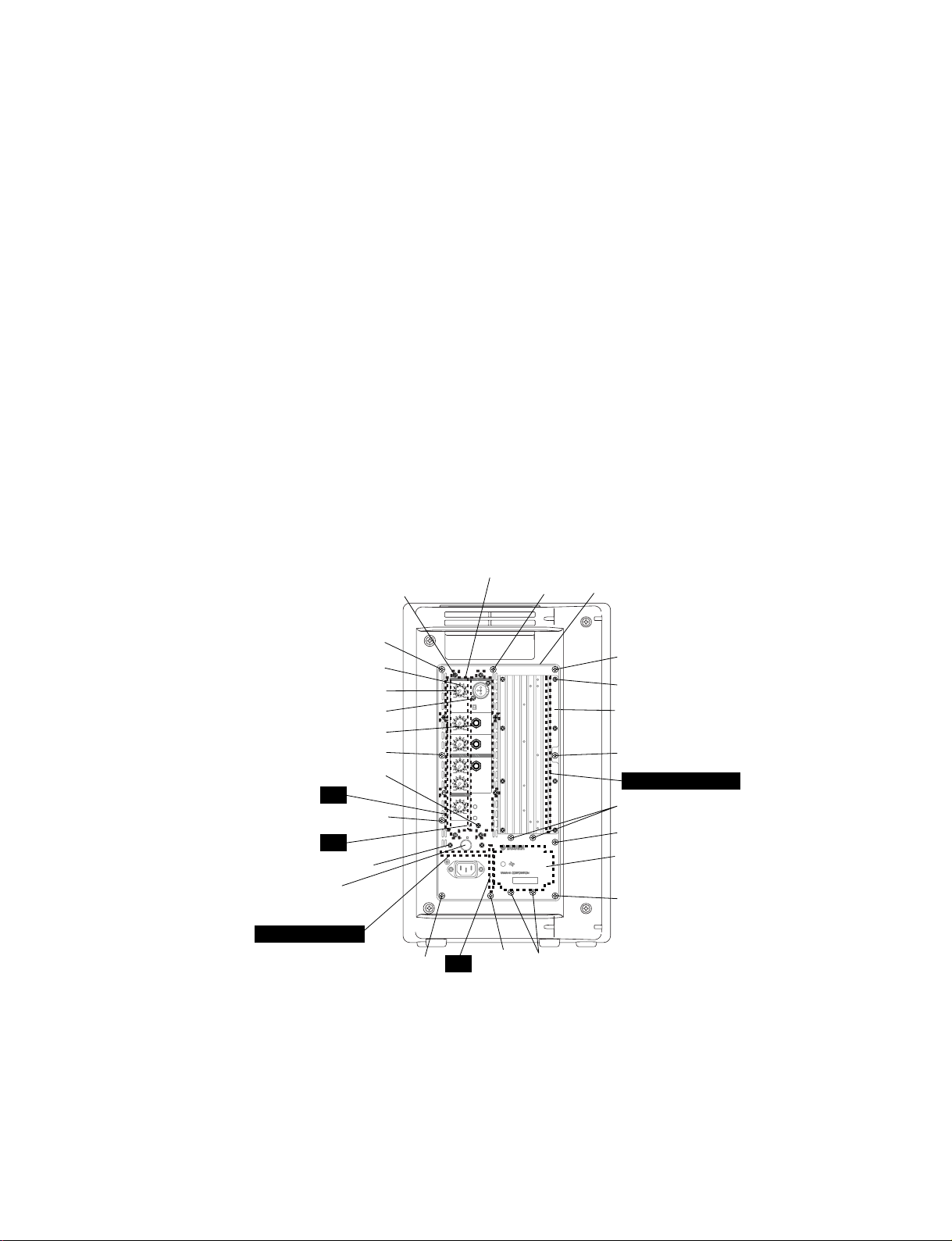
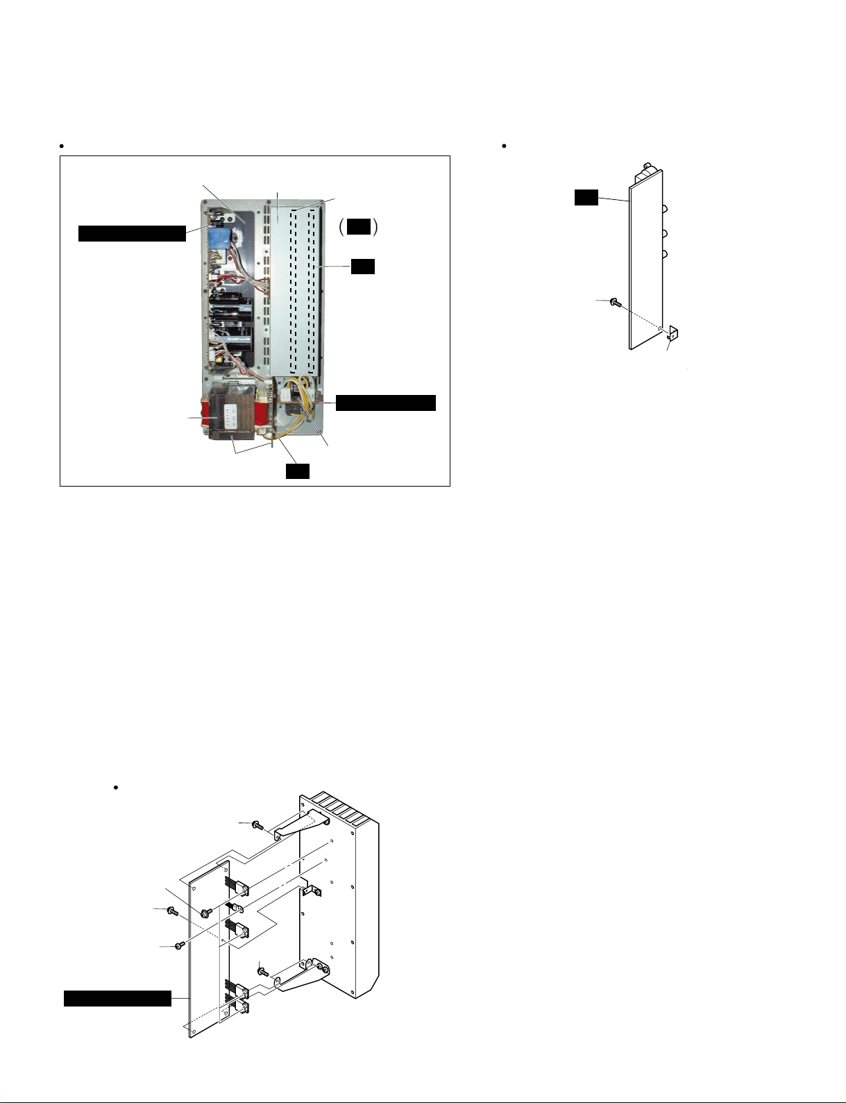
6. Amplifier Assembly
(Time required: About 1 minute)
6-1 Remove the ten (10) screws mar ked [30]. The
amplifier assembly can then be removed. (Fig.5)
7. EQ Circuit Board, IN PCB Assembly and
IN Circuit Board
(Time required: About 3 minutes each)
7-1 Remov e the amplifier assemb ly. (See procedure 6.)
7-2 Remove the eight (8) screws marked [210]. The
shield case assembly can then be removed. (Fig.5,
Photo.3)
7-3 EQ Circuit Board:
7-3-1 Remove the six (6) knobs marked [110] and the six
(6) hexagonal nuts marked [A]. The EQ circuit board
can then be removed. (Fig.5, Photo.3)
7-4 IN PCB Assembly and IN Circuit Board:
7-4-1 Remove the three (3) hexagonal nuts marked [130]
and the three (3) screws marked [160]. The IN PCB
assembly can then be removed. (Fig.5, Photo.3)
7-4-2 Remove the screw marked [150c]. The angle L can
then be removed from the IN circuit board. (Fig.6)
〈
Rear view
〉
[210] x 8
Shield case assembly
(シールドケースAss'y)
6. アンプAss'y(所要時間:約 1 分)
6-1 [30]のネジ10本を外して、アンプAss'yを外します。
(図5)
7. EQシート、IN シート Ass'y、IN シート
(所要時間:各約 3 分)
7-1 アンプ Ass'y を外します。(6 項参照)
7-2 [210]のネジ8本を外して、シールドケースAss'yを
外します。(図 5,写真 3)
7-3 EQシート:
7-3-1 [110]のノブ 6 個と[A]の六角ナット 6 個を外して、
EQ シートを外します。(図 5,写真 3)
7-4 IN シート Ass'y、IN シート:
7-4-1 [130]の特殊六角ナット 3 個と[160]のネジ 3 本を外
して、IN シート Ass'y を外します。(図 5,写真 3)
7-4-2 [150c]のネジ1本を外して、INシートからL金具を
外します。(図 6)
Amplifier assembly
(アンプAss'y)
[30]
[30]
[A] x 6
[110] x 6
[160] x 2
[130] x 3
EQ
IN
[100B] x 2
Push knob
(プッシュボタン)
[30]
[160]
[30]
INPUT
1
010
LEVEL
2
10
0
LEVEL
3
10
0
LEVEL
EQ
HIGH
+6-6
LOW
+3-3
MASTERMASTER
10
0
LEVEL
POWER
ON/OFF
AC IN
2
NEUTRIK
3
1
MIC(-50dB)
LINE(+4dB)
LINE
(-10dB)
LINE
(-10dB)
LINK OUT
(-10dB)
CLIP
POWER
POWERED SPEAKER
MODEL MSR100
PS
E
100V 65W 50/60HzÅ`
MADE IN CHINA
SER.NO.
******
[30]
[180] x 8
Power amplifier assembly
(パワーアンプAss'y)
[30]
POWER AMPLIFIER
[20]
[30]
Power transformer
(電源トランス)
[30]
POWER SWITCH
[30]
[30]
AC
[20]: Bonding Tapping Screw-B 4.0X8 BL BO (AAX43620)
[30]: Bind Head Tapping Screw-B 4.0X14 BL (AAX42170)
[100B]: Bonding Tapping Screw-B 3.0X10 BL BO (AAX12110)
[130]: Hexagonal Nut M12.0 BL
(特殊六角ナット)
[160]: Bonding Tapping Screw-B 3.0X10 BL BO (AAX12110)
[180]: Pan Head Tapping Screw-B 3.0X12 BL (AAX43370)
[210]: Bonding Tapping Screw-B 3.0X10 BL BO (AAX12110)
[A]: Hexagonal Nut
Washer
(+ボンディングBタイト)
(六角ナット)
(ワッシャー)
(+ボンディングBタイト)
(+バイントBタイト)
(+ボンディングBタイト)
(+ボンディングBタイト)
(+ナベタッピングネジB)
Fig.5
[20]
(図5)
9
MSR100/SMS100
)
Amplifier Assembly (アンプAss'y)
〈
Front view
Power amplifier assembly
(パワーアンプAss'y)
POWER AMPLIFIER
〉
Shield case assembly
(シールドケースAss'y)
IN PCB assembly
(INシートAss'y)
IN
EQ
POWER SWITCH
Power transformer
(電源トランス)
Power transformer assembly
(電源トランスAss'y)
Photo.3
(写真3)
Power switch assembly
(電源スイッチAss'y)
AC
8. Power Amplifier Assemb ly and POWER AMPLIFIER Circuit Board
(Time required: About 4 minutes)
8-1 Remov e the amplifier assemb ly. (See procedure 6.)
8-2 Remove the shield case assembly. (See procedure
7-2.)
8-3 Remove the eight (8) screws marked [180]. The
power amplifier assembly can then be removed.
(Fig.5, Photo.3)
8-4 Remove the scre w marked [P40], the five (5) scre ws
marked [P80] and the four (4) screws marked [P90].
The POWER AMPLIFIER circuit board can then be
removed. (Fig.7)
IN PCB Assembly
(INシートAss'y)
IN
[150c]
Angle L
(L金具
[150c]: Cup Screw-B
PW3.0X8 Y (AAX43390)
(+カップネジBタイト)
(図6)
Fig.6
8. パワーアンプAss'y、パワーアンプシート
(所要時間:約4 分)
8-1 アンプ Ass'y を外します。(6 項参照)
8-2 シールドケース Ass'y を外します。(7-2項参照)
8-3 [180]のネジ8本を外して、パワーアンプAss'y を外
します。(図 5,写真 3)
8-4 [P40]のネジ1 本と[P80]のネジ 5 本、[P90]のネジ 4
本を外して、パワーアンプシートを外します。(図7)
POWER AMPLIFIER
10
Power Amplifier Assembly
(パワーアンプAss'y)
[P80]
[P90]
[P80]
[P40]
[P80]
[P40]: Bind Head Tapping Screw-B 3.0X10 BL (AAX10840)
[P80]: Cup Screw-B PW3.0X8 Y (AAX43390)
[P90]: Cums Head Screw SP3.0X14 BL (AAX43410)
Fig.7
(図7)
(+カップネジBタイト)
(+カムス小ネジ)
(+バインドBタイト)

MSR100/SMS100
)
9. Power Transformer Assembly (Power
Transformer and AC Circuit Board)
(Time required: About 3 minutes)
9-1 Remov e the amplifier assemb ly. (See procedure 6.)
9-2 Remove the f our (4) scre ws marked [20]. The power
transformer assembly can then be remov ed. (Fig.5,
Photo.3)
9-3 Remove the power transformer soldered to the AC
circuit board. (Photo.4)
10. Power Switch Assembly and POWER
SWITCH Circuit Board
(Time required: About 3 minutes)
10-1 Remove the amplifier assemb ly. (See procedure 6.)
10-2 Remove the two (2) screws marked [100B]. The
power switch assemb ly can then be removed. (Fig.5,
Photo.3)
10-3 Remove the two (2) scre ws marked [90d]. The power
switch holder and the push knob can then be
removed from the POWER SWITCH circuit board.
(Fig.8)
Power Transformer Assembly
(電源トランスAss'y)
Power transformer
(電源トランス)
9. 電源トランスAss'y
(電源トランス、AC シート)
(所要時間:約 3 分)
9-1 アンプ Ass'y を外します。(6項参照)
9-2 [20]のネジ 4 本を外して、電源トランス Ass'y を外
します。(図 5,写真 3)
9-3 ACシートに半田付けされている電源トランスを外
します。(写真4)
10. 電源スイッチAss'y、電源スイッチシート
(所要時間:約 3 分)
10-1 アンプAss'y を外します。(6 項参照)
10-2 [100B]のネジ2本を外して、電源スイッチAss'yを
外します。(図 5,写真 3)
10-3 [90d]のネジ2 本を外して、電源スイッチシートか
ら電源スイッチ取付け金具とプッシュボタンを外し
ます。(図 8)
Power Switch Assembly
(電源スイッチAss'y)
[90d]
Push knob
(プッシュボタン
Soldering
(半田付け)
Photo.4 (写真4)
AC
Power switch holder
(電源スイッチ取付金具)
POWER SWITCH
[90d]: Flat Head Screw 3.0X6 BL (AAX42430)
(+皿小ネジM3X6)
(図8)
Fig.8
11

MSR100/SMS100
IC BLOCK DIAGRAM
(ICブロック図)
µPC4570HA (AAX42560)
Dual Operational Amplifier
EQ: IC201-203
IN: IC101,103
CIRCUIT BOARDS
+
-
1A2 3 4 5 6 7 8 9
+V -IN -V
+INOUT
AAA
(シート基板図)
+
B
-
+IN OUT
+V-IN
BBB
AC Circuit Board (6448D-20) ...........................................................12
EQ Circuit Board (6448B-20) ...........................................................14
IN Circuit Board (6448A-20).............................................................15
NETWORK Circuit Board (6448F-20) ..............................................16
POWER AMPLIFIER Circuit Board (6448C-20)...............................13
POWER SWITCH Circuit Board (6448E-20)....................................12
Note: See parts list for details of circuit board component parts.
注:シートの部品詳細はパーツリストをご参照下さい。
AC Circuit Board
to POWER AMPLIFIER
-CN302, CN304
Component side
POWER SWITCH Circuit Board
POWER
ON/ OFF
(部品側)
Pattern side(パターン側)
12
to AC IN
Component side
(部品側)
Pattern side(パターン側)
AC, POWER SWITCH: 374005

POWER AMPLIFIER: 374005
to NETWORK-P1, P2
to EQ-BC201
to EQ-BC202
to IN-BC102
to AC-BC803
Component side
(部品側)
POWER AMPLIFIER Circuit Board
13
Pattern side
(パターン側)
MSR100/SMS100

14
to POWER AMPLIFIER-CN305
MASTER LEVEL LOW
EQ
HIGH 3 LEVEL 2 LEVEL 1 LEVEL
to POWER AMPLIFIER-CN301
to IN-BC101
INPUT
Component side
(部品側)
EQ Circuit Board
MSR100/SMS100
Pattern side(パターン側)
EQ: 374005

IN: 374005
to EQ-CN201
to POWER AMPLIFIER-CN306
12
LINE
MIC/LINE
INPUT
3
LINE
LINK OUT
CLIP
RED GREEN
POWER
Component side
(部品側)
IN Circuit Board
Pattern side
(パターン側)
15
MSR100/SMS100

MSR100/SMS100
NETWORK Circuit Board
to Speaker LF
(WOOFER)
RED REDBLACK
to Speaker HF
(TWEETER)
YELLOW
to POWER AMPLIFIER-BC301
BLACK
BLUE
Component side
(部品側)
16
Pattern side
(パターン側)
NETWORK: 374005

MSR100/SMS100
INSPECTIONS
1. Test Conditions
(1) Measuring Voltage AC100V 50/60Hz (J)
(2) Load 6Ω
(3) Input 1KHz
(4) MASTER LEVEL VR MAX.
(5) Tone-control VR HIGH, LOW Center.
2. Environment
(1) Ambient Temperature 25 ± 5°C
(2) Ambient Humidity 65 ± 5%
3. Inspections
No.
1
(定格出力) (1%歪出力)
2
(歪率)
3
(LINKOUTレベル)
(負荷):
(入力):
(周囲環境)
(検査)
(項目)
Output Power
T. H. D.
LINK OUT Level
(検査)
(試験条件)
(測定電圧):
(
(
トーンコントロール
(周囲温度):
(周囲湿度):
INPUT1, SW-LINE
INPUT1 LEVEL=MAX.
INPUT1, SW-LINE
INPUT1 LEVEL=MAX.
INPUT2=-10dBu
INPUT2 LEVEL=MAX.
AC120V 60Hz (U, C, V)
AC240V 50Hz (A)
AC230V 50Hz (B, H, W)
AC220V 60Hz (K)
マスターレベル
VR):
VR):
(入力条件) (出力条件) (標準値) (限界値)
1%THD Output
80W Output
(80W出力)
LINK OUT
INPUT1, SW-MIC
INPUT1 LEVEL=MAX.
INPUT1, SW-LINE
Input Sensitivity
4
(入力感度)
INPUT1 LEVEL=MAX.
INPUT2
REF.: 100W Output
(基準:100W出力)
INPUT2 LEVEL=MAX.
INPUT3
INPUT3 LEVEL=MAX.
REF.: 1W Output
(基準:1W出力)
REF.: 1W Output
(基準:1W出力)
Frequency Response
5
(周波数特性)
INPUT1, SW-LINE
REF.: 1KHz
60Hz
10KHz
LOW = MIN.
REF.: 100Hz, LOW VR Center
LOW = MAX.
Tone-control
6
Characteristic
(トーンコン トロール特性 )
REF.: 100Hz, LOW VR Center
HIGH = MIN.
REF.: 1W Output
(基準:1W出力)
REF.: 10KHz, HIGH VR Center
HIGH = MAX.
REF.: 10KHz, HIGH VR Center
Signal To Noise
Ratio
7
(信号雑音比)
Residual Noise
8
(残留雑音)
Input Short
(入力短絡)
MASTER LEVEL=MIN.
SW-LINE
REF.: 100W Output
(基準:100W出力)
SP-OUT
(Note): 1dBu = 0.775V
Nominal LimitItems Output ConditionsInput Conditions
104W
0.02%
-9.5dBu
-50dBu
+3.5dBu
-10dBu
-10dBu
+4.6dB
+1.2dB
-3.0dB
+3.0dB
-5.5dB
-6.0dB
85dB
0.2mV
>100W
<0.1%
-10dBu ± 2dB
-50dBu ± 2dB
+4dBu ± 2dB
-10dBu ± 2dB
-10dBu ± 2dB
+5 ± 3dB
+1.5 ± 3dB
-3 ± 2dB
+3 ± 2dB
-6 ± 2dB
+6 ± 2dB
>80dB
<1.0mV
17

ABCDEFGHI
MSR100/SMS100
MSR100/SMS100 BLOCK DIAGRAM(ブロックダイアグラム)
1
INPUT1
(-50dB/+4dB)
INPUT2
LINE
(-10dB)
INPUT3
LINE
(-10dB)
LINK OUT
(-10dB)
IN
MIC/LINE
JK101
12
3
+
S101
GND
JK102
JK103
JK104
+15V
+
MIC AMP
Q101~104
IC101-1/2
6
7
+15V
+
-15V
-15V
+
IC101-2/2
IC103-1/2
(9P)
(9P)
+15V
9
42
+
5
-15V
IC103-2/2
68
+
MIC
(-50dB)
LINE
(+4dB)
9
5
EQ
VR201
IC202-2/2
IC202-1/2
(9P)
INPUT1
LEVEL
S101
8
Q105, 106
BC101 (8P)
-15V
+15V
CN201 (8P)
D111
CONTROL
CLIP (RED)
VR202
INPUT2
LEVEL
VR203
IC201-1/2
(9P)
+15V
9
326842
-
SUM
5
-15V
IC201-2/2
INPUT3
GND
D112
POWER
GND
GND
LEVEL
-
8
7
LOW
BOOST
HPF
+15V
9
5
-15V
VR204
IC203-1/2
CLIP DETECTOR
7
(GREEN)
IC104
+15V
-15V
(3P)
+15V
2
GND
IC105 (3P)
3
-15V
1
GND
13
POWER AMPLIFIER
GND
GND
2
BC102 (3P)
+B1
-B1
CN306 (3P)
+B2
D308
CN305 (2P)
-B2
IC203-2/2
(9P)
EQ
LOW
+15V
9
5
-15V
EQ
LOW
BC202 (2P)
HIGH
EQ
HIGH
+B2
-B2
8
VR205
+B2
BC201 (5P)
VR206
MASTER
LEVEL
VOLTAGE AMP
R234
Q201
~207
R235
-B2
2
3
4
POWER AMP
+B2
AC IN
FG
MSR100/SMS100
POWER SWITCH
C802
C801
POWER
ON/OFF
BC801 (2P)
F801
S801
AC
BC802 (2P)
CN801 (2P)
Primary Secondary
Power Transformer
3
1
2
4
5
6
7
F802
F803
T801
GND
CN302 (3P)
BC803 (5P)
CN304 (2P)
D309~312
NETWORK
L401
-B2
RLY301
RED
P1
P2
C402 C403
PROTECTION
GND
BLACK
BC301 (2P) CN301 (5P)
Q308~312
MSR100/SMS100 BLOCK DIAGRAM
L402
RED
+
P3
Speaker LF
C401
P4
P5
BLACK
YELLOW
(WOOFER)
+
Speaker HF
(TWEETER)
P6
BLUE
(ブロックダイアグラム)
5
6
1

ABCDEFGHI
MSR100/SMS100 CIRCUIT DIAGRAM 1/3 (AC, NETWORK, POWER AMPLIFIER, POWER SWITCH)
MSR100/SMS100
POWER AMPLIFIER
1
2
RED
to EQ-BC201
3
BLACK
NETWORK
RED
BLACK
YELLOW
BLUE
+
Speaker LF
(WOOFER)
+
Speaker HF
(TWEETER)
ZA1C2A00104
POWER
ON/ OFF
POWER
to EQ-BC202
4
to IN-BC102
5
Destination
J
U, C
A
B
H
V
W
K
AC Cord F801 T801 Power Supply
V7240300
V6284300
V6284400
V6283900
V6284400
V6284300
V6284400
V6284400
AAX43570
AAX43570
AAX43600
AAX43600
AAX43600
AAX43570
AAX43600
AAX43600
2.5A 250V
2.5A 250V
T1AL 250V
T1AL 250V
T1AL 250V
2.5A 250V
T1AL 250V
T1AL 250V
AAX42250
AAX42260
AAX42270
AAX42280
AAX42280
AAX42260
AAX42280
AAX42290
AC100V 50/60Hz
AC120V 60Hz
AC240V 50Hz
AC230V 50Hz
AC230V 50Hz
AC120V 60Hz
AC230V 50Hz
AC220V 60Hz
ZA1C2A00104
3
(MY)
(FS)
SWITCH
ZA1C2A00104
AC
: Mylar Capacitor
: Flame Proof C. Resistor
Power Transformer
Secondary
3
ZA1C2A00104
(
マイラーコンデンサー
(
不燃化カーボン抵抗
3
AC IN
Primary
3
)
)
POWER AMP BLOCK
6
MSR100/SMS100
MSR100/SMS100 CIRCUIT DIAGRAM 1/3 (AC, NETWORK, POWER AMPLIFIER, POWER SWITCH)
2

ABCDEFGHI
MSR100/SMS100 CIRCUIT DIAGRAM 2/3 (EQ)
EQ
INPUT1
LEVEL
to IN-BC101
INPUT2
LEVEL
INPUT3
LEVEL
MSR100/SMS100
1
OP AMP
2
OP AMP
OP AMP
3
OP AMP
OP AMP
EQ LOW
EQ HIGH
(MY)
: Mylar Capacitor
(FS)
: Flame Proof C. Resistor
OP AMP
MASTER
LEVEL
(
マイラーコンデンサー
(
不燃化カーボン抵抗
to POWER AMPLIFIER
-CN301
4
to POWER AMPLIFIER
-CN305
5
ZA1C2A00203
)
)
CONTROL BLOCK
2
6
MSR100/SMS100
MSR100/SMS100 CIRCUIT DIAGRAM 2/3 (EQ)
3

ABCDEFGHI
MSR100/SMS100 CIRCUIT DIAGRAM 3/3 (IN)
MSR100/SMS100
IN
1
INPUT1
LINE
MIC
OP AMP
2
to EQ-CN201
NJM78M15FA(AAX42930)
REGULATOR +15V
3
OP AMP
INPUT2
LINE
4
OP AMP
INPUT3
LINE
5
OP AMP
GREEN
POWER CLIP
RED
REGULATOR +15V
REGULATOR -15V
ZA1C2A00302
to POWER AMPLIFIER-CN306
1
1
2
3
1: INPUT
2: GND
3: OUTPUT
NJM79M15FA(AAX42940)
REGULATOR -15V
1
2
3
1: COMMON
2: INPUT
3: OUTPUT
LINK OUT
INPUT BLOCK
(MY)
: Mylar Capacitor
(FS)
6
MSR100/SMS100
: Flame Proof C. Resistor
(
マイラーコンデンサー
(
不燃化カーボン抵抗
4
)
)
MSR100/SMS100 CIRCUIT DIAGRAM 3/3 (IN)

POWERED SPEAKER
MSR100/SMS100
PARTS LIST
CONTENTS
OVERALL ASSEMBLY .............................................. 2
AMPLIFIER ASSEMBLY .................................. 4
ELECTRICAL PARTS ........................................ 6-11
Notes : DESTINATION ABBREVIATIONS
A : Australian model
B : British model
C : Canadian model
D : German model
E : European model
F : French model
H : North European model
I : Indonesian model
J : Japanese model
K : Korean model
(目次)
(総組立)
(アンプAssy)
(電気部品)
M: South African model
O: Chinese model
Q: South-east Asia model
T : Taiwan model
U : U.S.A. model
V : General export model (110V)
W: General export model (220V)
N,X: General export model
Y : Export model
WARNING
Components having special characteristics are marked and must be replaced with parts having
specification equal to those originally installed.
印の部品は、安全を維持するために重要な部品です。交換する場合は、安全のために必ず指定の部品をご
使用下さい。
The numbers “QTY” show quantities for each unit.
The parts with “--” in “PART NO.” are not available as spare parts.
This mark “ } ” in the REMARKS column means these parts are interchangeable.
The second letter of the shaded (
The second letter of the shaded (
部品価格ランクは、変更になることがあります。
QTY欄に記されている数字は、各ユニット当たりの使用個数です。
PARTNO.が--の部品は、サービス用部品として準備されておりません。
REMARKS欄の「}」マークの部品は、併用部品です。
網掛けの付いたPARTNO.の2番目の文字は「ゼロ」ではなく、「オー」です。
網掛けの付いたPARTNO.の2番目の文字は「イチ」ではなく、「アイ」です。
) part number is O, not zero.
) part number is I, not one.

MSR100/SMS100
OVERALL ASSEMBLY
N30
N10
10e
N40
10d
N20
10g
(総組立)
10c
10a
10b
17
16
50
(アンプAss'y)
Rear cabinet unit
(リアキャビネット部)
30
20
Amplifier assembly:
See page 4.
15
Network assembly
(ネットワークAss'y)
10
Rear cabinet assembly
(リアキャビネットAss'y)
90b
90a
90c
80
10f
10h
10d
40c
40b
40a
40b
45
46
40d
40c
100
90d
90e
90f
90c
90b
60
Front grille assembly
90
(フロントグリルAss'y)
Front cabinet assembly
(フロントキャビネットAss'y)
50
Front cabinet unit
(フロントキャビネット部)
40
2

MSR100/SMS100
REF NO.
PART NO. DESCRIPTION REMARKS
10 Rear Cabinet Assembly 378134
*
*
*
*
*
*
*
*
*
*
*
*
*
AAX42140
10a Rear Cabinet 369175
10b Damping Material A FELT REAR 369668
10c Damping Material B FELT TOP 370586
10d Damping Material C FELT SIDE 370587 8
AAX10840
10e Bind Head Tapping Screw-B 3.0X10 BL 075640 4
AAX42150
10f Misc Bolt 369366 2
AAX42300
10g Flange Nut M12 369426 2
AAX42160
10h Pan Head Screw PW8.0X25 BL 371498 2
15 Network Assembly
AAX31970
16 Cushion Bush 331850
AAX46130
17 Cushion 40X100 368780
20 Amplifier Assembly J
20 Amplifier Assembly U,C,V
20 Amplifier Assembly A
20 Amplifier Assembly H,W,B
20 Amplifier Assembly K
AAX42170
30 Bind Head Tapping Screw-B 4.0X14 BL 075662 10
AAX42180
40 Front Cabinet Assembly 378133
40a Front Cabinet 369176
40b Cushion 7.0X265 373196 2
40c Cushion 7.0X440 373195 2
40d Damping Material FELT DUCT 374239
AAX42190
45 Speaker HF TWEETER 369357
AAX42200
46 Bind Head Tapping Screw-B 4.0X20 BL 075668 2
AAX42210
50 Bind Head Tapping Screw-A 5.0X35 BL 371272 9
AAX42220
60 Speaker LF WOOFER 369356
AAX42230
80 Bind Head Tapping Screw-B 4.0X18 BL 075667 4
AAX42310
90 Front Grille Assembly 375596
90a Front Grille 369179
90b Cushion A Grille 6.0X245 369573 2
90c Cushion B Grille 6.0X225 369576 2
90d Logo Badge YAMAHA 369377
90e Cushion Badge 369669
90f Bush Nut 031814 2
AAX12100
100 Bind Head Tapping Screw-B 4.0X10 BL 075659 4
OVERALL ASSEMBLY MSR100/SMS100
--
--
--
--
--
--
--
--
--
--
--
--
--
--
--
--
--
--
--
--
部品名
総組立
リアキャビネットAssy
リアキャビネット
吸音材A
吸音材B
吸音材C
+バイントBタイト
特殊ボルト
フランジナットM12
ナベ小ネジ平ワッシャ付き
ネットワークAssy
クッション
クッション
アンプAssy J
アンプAssy U,C
アンプAssy A
アンプAssy H
アンプAssy K
+バイントBタイト
フロントキャビネットAssy
フロントキャビネット
ガスケット
ガスケット
吸音材
スピーカHF
+バインドBタイト
+バインドAタイト
スピーカLF
+バインドBタイト
フロントグリルAssy
フロントグリル
クッショングリルA
クッショングリルB
ロゴバッジ
クッション バッジ
ブッシュナット
+バインドBタイト
QTY
RANK
--
AAX42320
N10 Circuit Board NETWORK 374307,374308
*
N20 Holder C Network 370892
N30 Holder D Network 370893
AAX43390
N40 Cup Screw-B PW3.0X8 Y 075164 4
*
V7240300
V6284300
V6283900
V6284400
Network Assembly
--
--
ACCESSORIES
AC Cord 2P 125V 10A 2.5m J 05
AC Cord 3P 125V 10A 2.5m U,C,V 05
AC Cord 3P 250V 10A 2.5m B 13A FUSE INSIDE 08
AC Cord 3P 250V 10A 2.5m H,W,A,K 06
ネットワークAssy
ネットワークシート
ネットワーク固定金具C
ネットワーク固定金具D
+カップネジBタイト
附属品
電源コード
電源コード
電源コード
電源コード
: New Parts RANK: Japan only
3

MSR100/SMS100
AMPLIFIER ASSEMBLY
P80
P80
P80
IN PCB assembly
(INシートAss'y)
150
Shield case assembly
(シールドケースAss'y)
170
150a
(アンプAssy)
P40
P60
P90
P40
P10
P40
P50
P70
P40
200
P30
180
190
Power amplifier assembly
(パワーアンプAss'y)
160
210
110
170b
170a
10a
10b
150c
150b
90a
Power switch assembly
90
(電源スイッチAss'y)
Power transformer assembly
10
(電源トランスAss'y)
140
90d
90b
90c
70
100
60
(ACインレットAss'y)
220
130
20
160
40
50
30a
30c
30b
30
AC-IN connector assembly
4

MSR100/SMS100
REF NO.
PART NO. DESCRIPTION REMARKS
10 Power Transformer Assembly J
10 Power Transformer Assembly U,C,V
10 Power Transformer Assembly A
10 Power Transformer Assembly H,W,B
10 Power Transformer Assembly K
AAX42250
10a Power Transformer AC100V 50/60Hz J 369545
*
*
*
*
*
*
*
*
*
*
*
*
*
*
*
*
*
*
*
*
*
*
*
*
*
*
*
AAX42260
10a Power Transformer AC120V 60Hz U,C,V 369546
AAX42270
10a Power Transformer AC240V 50Hz A 369547
AAX42280
10a Power Transformer AC230V 50Hz H,W,B 369548
AAX42290
10a Power Transformer AC220V 60Hz K 369550
AAX42420
10b Circuit Board AC 374307,374308
AAX43620
20 Bonding Tapping Screw-B 4.0X8 BL BO 369365 4
30 AC-IN Connector Assembly
AAX42330
30a AC Inlet AC IN 369516
30b Earth Wire M4.0 369543
30c Connector Assembly 2P-VH L=150 369542
AAX42340
40 Flat Head Tapping Screw-B 3.0X8 BL 075145 2
AAX42350
50 Screw 4.0X14 BL 369111
AAX42360
60 Toothed Lock Washer B4.0 ZMC3 075773
AAX42370
70 Hexagonal Nut M4 075704
90 Power Switch Assembly J J,U,C,V
90 Power Switch Assembly B A,B,H,W,K
AAX42380
90a Circuit Board POWER SWITCH J,U,C,V 374307
AAX42390
90a Circuit Board POWER SWITCH A,B,H,W,K 374308
AAX42410
90b Push Knob Black POWER ON/OFF 366303
90c Holder Power Switch 366302
AAX42430
90d Flat Head Screw 3.0X6 BL 075197 2
AAX12110
100 Bonding Tapping Screw-B 3.0X10 BL BO 084772 2
AAX42400
110 Knob INPUT,EQ,MASTER 369217 6
130 Hexagonal Nut M12.0 BL 372781 3
AAX42440
140 Circuit Board EQ 374307,374308
150 IN PCB Assembly
AAX42450
150a Circuit Board IN 374307,374308
150b Angle L 077876
AAX43390
150c Cup Screw-B PW3.0X8 Y 075164
AAX12110
160 Bonding Tapping Screw-B 3.0X10 BL BO 084772 3
170 Shield Case Assembly
170a Insulation Sheet 369421
170b Mold Edge Guard L=18 371112 3
AAX43370
180 Pan Head Tapping Screw-B 3.0X12 BL 075512 8
190 Power Amplifier Assembly
AAX43420
200 Rear Panel J 366296
AAX43430
200 Rear Panel U,C,V 369221
AAX43440
200 Rear Panel A 369222
AAX43450
200 Rear Panel H,W,B 369223
AAX43460
200 Rear Panel K 374669
AAX43650
200 Rear Panel J(SMS100) 374668
AAX12110
210 Bonding Tapping Screw-B 3.0X10 BL BO 084772 8
220 Cord Holder SKB-1M WH 080558 7
AMPLIFIER ASSEMBLY MSR100/SMS100
--
Amplifier Assembly J
--
Amplifier Assembly U,C,V
--
Amplifier Assembly A
--
Amplifier Assembly H,W,B
--
Amplifier Assembly K
--
--
--
--
--
--
--
--
--
--
--
--
--
--
--
--
--
--
--
部品名
アンプAssy
アンプAssy J
アンプAssy U,C
アンプAssy A
アンプAssy H
アンプAssy K
電源トランスAssy
電源トランスAssy
電源トランスAssy
電源トランスAssy
電源トランスAssy
電源トランスJ
電源トランスU
電源トランスA
電源トランスB
電源トランスK
ACシート
+ボンディングBタイト
ACインレットAssy
ACインレット
アース線
インレット束線2P
+皿タッピングネジB
PIN TORXネジ
歯付座金外歯形
フランジ付き六角ナット
電源スイッチAssy
電源スイッチAssy
電源スイッチシート J
電源スイッチシート B
プッシュボタン
電源スイッチ取付け金具
+皿小ネジM3x6
+ボンディングBタイト
ノブ
特殊六角ナット
EQシート
INシートAssy
INシート
L金具
+カップネジBタイト
+ボンディングBタイト
シールドケース(保護付き
絶縁シート
エッジガード
+ナベタッピングネジB
パワーアンプ Assy
リアパネル印刷品 J
リアパネル印刷品 U,C
リアパネル印刷品 A
リアパネル印刷品 H
リアパネル印刷品 K
リアパネル印刷品 J
+ボンディングBタイト
インシュロックタイ
QTY
RANK
--
*
*
*
*
AAX43380
P30 Heat Sink 366299
AAX10840
P40 Bind Head Tapping Screw-B 3.0X10 BL 075640 6
P50 Angle A RIGHT 366300
P60 Angle B LEFT 366301
P70 Angle L 077876
AAX43390
P80 Cup Screw-B PW3.0X8 Y 075164 5
AAX43410
P90 Cums Head Screw SP3.0X14 BL 359580 4
: New Parts RANK: Japan only
AAX43020
P10 Circuit Board POWER AMPLIFIER 374307,374308
Power Amplifier Assembly
--
--
--
パワーアンプ Assy
パワーアンプシート
放熱器
バインドBタイト
取付け金具A
取付け金具B
取付け金具
+カップネジBタイト
+カムス小ネジ
5

MSR100/SMS100
ELECTRICAL PARTS
REF NO.
PART NO. DESCRIPTION REMARKS
*
*
*
*
*
*
*
*
*
*
*
*
*
*
*
*
*
*
*
*
*
*
*
*
*
*
*
*
*
*
*
*
*
*
*
*
*
*
*
AAX42420
AAX42440
AAX42450
AAX42320
AAX43020
AAX42380
AAX42390
AAX42420
AAX43540
BC803 Connector Base Post 5P B5B-XH-A 081504
AAX43670
CN801 Connector Assembly 2P-170 SDN-51067 369541
F802 Fuse 3.15A 250V 052792
AAX35880
F803 Fuse 3.15A 250V 052792
AAX35880
JB0 Jumper Wire
AAX42440
BC201 Base Post 5P B5B-EH 081506
AAX28380
BC202 Base Post 2P B2B-EH 081439
AAX42460
C201 Electrolytic Cap. 10/35V 066288
AAX12070
-203 Electrolytic Cap. 10/35V 066288
AAX12070
C207 Electrolytic Cap. 10/35V 066288
AAX12070
-209 Electrolytic Cap. 10/35V 066288
AAX12070
C211 Mylar Capacitor 0.1 065007
AAX11180
C212 Mylar Capacitor 0.1 065007
AAX11180
C213 Electrolytic Cap. 10/35V 066288
AAX12070
C214 Mylar Capacitor 0.27 064926
AAX42470
C215 Mylar Capacitor 3900P 065099
AAX12450
C216 Mylar Capacitor 0.27 064926
AAX42470
C217 Ceramic Tubular Capacitor 68P 049192
AAX42480
C218 Electrolytic Cap. 10/35V 066288
AAX12070
-220 Electrolytic Cap. 10/35V 066288
AAX12070
C221 Mylar Capacitor 0.0012 065014
AAX11190
C222 Ceramic Tubular Capacitor 100P 051723
AAX12170
C223 Mylar Capacitor 2200P 065055
AAX42490
C224 Electrolytic Cap. 47/10V 066421
AAX42500
C225 Ceramic Capacitor 4P/500V 065783
AAX42510
C226 Ceramic Tubular Capacitor 22P 051094
AAX09490
C227 Ceramic Capacitor 100P/500V 065700
AAX42520
C228 Electrolytic Cap. 10/35V 066288
AAX12070
C229 Electrolytic Cap. 10/35V 066288
AAX12070
C231 Ceramic Capacitor 0.01 065452
AAX42530
C233 Ceramic Capacitor 0.01 065452
AAX42530
C234 Electrolytic Cap. 22/50V 066352
AAX12250
C235 Electrolytic Cap. 22/50V 066352
AAX12250
C236 Ceramic Capacitor 0.01 065452
AAX42530
-241 Ceramic Capacitor 0.01 065452
AAX42530
C243 Ceramic Tubular Capacitor 22P 051094
AAX09490
C244 Electrolytic Cap. 10/35V 066288
AAX12070
C245 Electrolytic Cap. 10/35V 066288
AAX12070
C246 Mylar Capacitor 0.15 064914
AAX11160
C247 Mylar Capacitor 0.082 065152
AAX42540
C248 Ceramic Tubular Capacitor 100P 051723
AAX12170
CN201 Connector Assembly EQ 8P-110 SCN-EH 369535
D201 Diode 1SS133 069460
AAX42550
-205 Diode 1SS133 069460
AAX42550
IC201 IC UPC4570HA OP AMP 070111
AAX42560
-203 IC UPC4570HA OP AMP 070111
AAX42560
Q201 Transistor 2SA1174 FP 068608
AAX42570
Q202 Transistor 2SA1174 FP 068608
AAX42570
Q203 Transistor 2SC2785 KEF 068806
AAX42580
Q204 Transistor 2SA1174 FP 068608
AAX42570
Q205 Transistor 2SC2785 KEF 068806
AAX42580
Q206 Transistor 2SA1145 OY 068602
AAX42590
Q207 Transistor 2SC2705 OY 068796
AAX42600
Q210 Digital Transistor DT A124ESA 069250
AAX41610
Q211 Transistor 2SC2785 KEF 068806
AAX42580
Q212 Transistor 2SC2785 KEF 068806
AAX42580
: New Parts RANK: Japan only
ELECTRICAL PARTS MSR100/SMS100
Circuit Board AC (6448D-20) 374307,374308
Circuit Board EQ (6448B-20) 374307,374308
Circuit Board IN (6448A-20) 374307,374308
Circuit Board NETWORK (6448F-20) 374307,374308
Circuit Board POWER AMPLIFIER (6448C-20) 374307,374308
Circuit Board POWER SWITCH J,U,C,V(6448E-20) 374307
Circuit Board POWER SWITCH A,B,H,W,K(6448E-20) 374308
Circuit Board AC (6448D-20) 374307,374308
Fuse Holder EYF-52BCT 074277 4
--
--
Circuit Board EQ (6448B-20) 374307,374308
Jumper Wire
--
--
(電気部品)
部品名
電気部品
ACシート
EQシート
INシート
ネットワークシート
パワーアンプシート
電源スイッチシート J
電源スイッチシート B
ACシート
ヒューズホルダ
コネクタ5P
束線2P
ヒューズ
ヒューズ
ジャンパー線
EQシート
ジャンパー線
コネクタ 5P
コネクタ 2P
ケミコン
ケミコン
ケミコン
ケミコン
マイラコン
マイラコン
ケミコン
マイラコン(W=6)
マイラコン
マイラコン(W=6)
円筒型セラコン
ケミコン
ケミコン
マイラコン
円筒型セラコン
マイラコン
ケミコン
セラコン
円筒型セラコン
セラコン
ケミコン
ケミコン
セラコン
セラコン
ケミコン
ケミコン
セラコン
セラコン
円筒型セラコン
ケミコン
ケミコン
マイラコン(W=6)
マイラコン
円筒型セラコン
束線EQ 8P
ダイオード
ダイオード
IC
IC
トランジスタ
トランジスタ
トランジスタ
トランジスタ
トランジスタ
トランジスタ
トランジスタ
デジタルトランジスタ
トランジスタ
トランジスタ
QTY
RANK
6

MSR100/SMS100
REF NO.
PART NO. DESCRIPTION REMARKS
R201 Carbon Resistor 10K 1/6W 067074
*
*
*
*
*
*
*
*
*
*
*
*
*
*
*
*
*
*
*
*
*
*
*
*
*
*
*
*
*
*
*
*
*
*
*
*
*
*
*
*
*
*
*
*
*
*
*
*
*
*
*
*
AAX42610
R202 Carbon Resistor 10K 1/6W 067074
AAX42610
R203 Carbon Resistor 3.9K 1/6W 067223
AAX42620
R204 Carbon Resistor 10K 1/6W 067074
AAX42610
R205 Carbon Resistor 12K 1/6W 067099
AAX42630
R206 Carbon Resistor 10K 1/6W 067074
AAX42610
R207 Carbon Resistor 100K 1/6W 067079
AAX42640
R208 Carbon Resistor 56K 1/6W 067273
AAX42650
R209 Carbon Resistor 4.7K 1/6W 067243
AAX42660
R210 Carbon Resistor 1.5K 1/6W 067114
AAX42680
R211 Carbon Resistor 10K 1/6W 067074
AAX42610
R213 Carbon Resistor 4.7K 1/6W 067243
AAX42660
R215 Carbon Resistor 2.2K 1/6W 067155
AAX42980
R217 Carbon Resistor 1.5K 1/6W 067114
AAX42680
R218 Carbon Resistor 33K 1/6W 067207
AAX42690
R219 Carbon Resistor 10K 1/6W 067074
AAX42610
R220 Carbon Resistor 10K 1/6W 067074
AAX42610
R221 Carbon Resistor 22K 1/6W 067160
AAX42700
R222 Carbon Resistor 1.2K 1/6W 067096
AAX42710
R223 Carbon Resistor 47K 1/6W 067248
AAX42720
R224 Carbon Resistor 330 1/6W 067200
AAX42730
R225 Carbon Resistor 10K 1/6W 067074
AAX42610
R226 Carbon Resistor 180 1/6W 067129
AAX42740
R227 Flame Proof C. Resistor 180 1/6W(FS) 044817
AAX42850
R228 Carbon Resistor 47K 1/6W 067248
AAX42720
R229 Carbon Resistor 1.2K 1/6W 067096
AAX42710
R230 Flame Proof C. Resistor 180 1/6W(FS) 044817
AAX42850
R231 Flame Proof C. Resistor 150 1/4W (FS) 067407
AAX42750
R232 Carbon Resistor 47K 1/6W 067248
AAX42720
R233 Flame Proof C. Resistor 47 1/4W(FS) 067450
AAX42760
R234 Flame Proof C. Resistor 10 1/4W(FS) 044452 01
AAX11870
R235 Flame Proof C. Resistor 10 1/4W(FS) 044452 01
AAX11870
R236 Carbon Resistor 100K 1/6W 067079
AAX42640
-238 Carbon Resistor 100K 1/6W 067079
AAX42640
R239 Carbon Resistor 10K 1/6W 067074
AAX42610
R240 Carbon Resistor 1M 1/6W 067083
AAX42770
R241 Carbon Resistor 1M 1/6W 067083
AAX42770
R242 Carbon Resistor 8.2K 1/6W 067313
AAX42780
R243 Carbon Resistor 8.2K 1/6W 067313
AAX42780
R246 Carbon Resistor 22K 1/6W 067160
AAX42700
R247 Carbon Resistor 10K 1/6W 067074
AAX42610
R248 Carbon Resistor 100 1/6W 067065
AAX42790
R249 Carbon Resistor 100K 1/6W 067079
AAX42640
R250 Carbon Resistor 5.6K 1/6W 067269
AAX42800
R251 Carbon Resistor 10K 1/6W 067074
AAX42610
R252 Carbon Resistor 6.8K 1/6W 067294
AAX42810
R253 Carbon Resistor 68K 1/6W 067297
AAX42820
R254 Carbon Resistor 1K 1/6W 067069
AAX42830
VR201 Rotary Variable Resistor 15A20K XVB12111YNP INPUT1 LEVEL 369511
AAX42840
VR202 Rotary Variable Resistor 15A20K XVB12111YNP INPUT2 LEVEL 369511
AAX42840
VR203 Rotary Variable Resistor 15A20K XVB12111YNP INPUT3 LEVEL 369511
AAX42840
VR204 Rotary Variable Resistor B2K CC XVB12111YNP EQ LOW 369512
AAX42860
VR205 Rotary Variable Resistor B2K CC XVB12111YNP EQ HIGH 369512
AAX42860
VR206 Rotary Variable Resistor 15A20K XVB12111YNP MASTER LEVEL 369511
AAX42840
部品名
カーボン抵抗
カーボン抵抗
カーボン抵抗
カーボン抵抗
カーボン抵抗
カーボン抵抗
カーボン抵抗
カーボン抵抗
カーボン抵抗
カーボン抵抗
カーボン抵抗
カーボン抵抗
カーボン抵抗
カーボン抵抗
カーボン抵抗
カーボン抵抗
カーボン抵抗
カーボン抵抗
カーボン抵抗
カーボン抵抗
カーボン抵抗
カーボン抵抗
カーボン抵抗
不燃化カーボン抵抗
カーボン抵抗
カーボン抵抗
不燃化カーボン抵抗
不燃化カーボン抵抗ヨコ型
カーボン抵抗
不燃化カーボン抵抗ヨコ型
不燃化カーボン抵抗タテ型
不燃化カーボン抵抗タテ型
カーボン抵抗
カーボン抵抗
カーボン抵抗
カーボン抵抗
カーボン抵抗
カーボン抵抗
カーボン抵抗
カーボン抵抗
カーボン抵抗
カーボン抵抗
カーボン抵抗
カーボン抵抗
カーボン抵抗
カーボン抵抗
カーボン抵抗
カーボン抵抗
ボリウム
ボリウム
ボリウム
ボリウム
ボリウム
ボリウム
QTY
RANK
*
*
*
*
*
*
*
AAX42450
BC101 Connector Base Post 8P B8B-EH 081541
AAX42880
BC102 Connector Base Post 3P B3B-EH 081465
AAX28370
C101 Ceramic Capacitor 0.01 065452
AAX42530
C102 Electrolytic Cap. 22/50V 066352
AAX12250
C103 Electrolytic Cap. 22/50V 066352
AAX12250
C104 Ceramic Tubular Capacitor 100P 051723
AAX12170
C105 Ceramic Tubular Capacitor 100P 051723
AAX12170
C106 Mylar Capacitor 1000P 064995
AAX42870
C107 Electrolytic Cap. 220/16V 066361
AAX42890
C108 Ceramic Tubular Capacitor 10P 369506
AAX42900
-110 Ceramic Tub ular Capacitor 10P 369506
AAX42900
C111 Electrolytic Cap. 22/50V 066352
AAX12250
C112 Electrolytic Cap. 22/50V 066352
AAX12250
C113 Ceramic Tubular Capacitor 100P 051723
AAX12170
: New Parts RANK: Japan only
Circuit Board IN (6448A-20) 374307,374308
INシート
コネクタ 8P
コネクタ 3P
セラコン
ケミコン
ケミコン
円筒型セラコン
円筒型セラコン
マイラコン
ケミコン
円筒型セラコン
円筒型セラコン
ケミコン
ケミコン
円筒型セラコン
7

MSR100/SMS100
REF NO.
PART NO. DESCRIPTION REMARKS
C114 Ceramic Tubular Capacitor 22P 051094
AAX09490
C115 Ceramic Tubular Capacitor 22P 051094
AAX09490
C116 Ceramic Tubular Capacitor 10P 369506
*
*
*
*
*
*
*
*
*
*
*
*
*
*
*
*
*
*
*
*
*
*
*
*
*
*
*
*
*
*
*
*
*
*
*
*
*
*
*
*
*
*
*
*
*
*
*
*
*
AAX42900
C117 Electrolytic Cap. 10/35V 066288
AAX12070
C118 Electrolytic Cap. 10/35V 066288
AAX12070
C119 Ceramic Tubular Capacitor 22P 051094
AAX09490
C120 Electrolytic Cap. 10/35V 066288
AAX12070
C121 Ceramic Tubular Capacitor 100P 051723
AAX12170
C122 Ceramic Tubular Capacitor 22P 051094
AAX09490
C123 Ceramic Tubular Capacitor 22P 051094
AAX09490
C124 Electrolytic Cap. 10/35V 066288
AAX12070
C125 Ceramic Tubular Capacitor 100P 051723
AAX12170
C126 Ceramic Tubular Capacitor 22P 051094
AAX09490
C133 Ceramic Capacitor 0.01 065452
AAX42530
-136 Ceramic Capacitor 0.01 065452
AAX42530
C137 Electrolytic Cap. 22/50V 066352
AAX12250
C138 Ceramic Capacitor 0.01 065452
AAX42530
C139 Electrolytic Cap. 22/50V 066352
AAX12250
C140 Ceramic Capacitor 0.01 065452
AAX42530
C141 Electrolytic Cap. 22/50V 066352
AAX12250
C142 Electrolytic Cap. 22/50V 066352
AAX12250
C143 Electrolytic Cap. 10/35V 066288
AAX12070
D101 Diode 1SS133 069460
AAX42550
-110 Diode 1SS133 069460
AAX42550
D111 LED Red SLR-56VR CLIP 069836
AAX42910
D112 LED Green SLR-56MG POWER 069930
AAX42920
IC101 IC UPC4570HA OP AMP 070111
AAX42560
IC103 IC UPC4570HA OP AMP 070111
AAX42560
IC104 IC NJM78M15FA REGULATOR +15V 070366
AAX42930
IC105 IC NJM79M15FA REGULATOR -15V 070445
AAX42940
JK101 Cannon Connector NC3FAH2-0 INPUT1 350274 06
AAX29350
JK102 Phone Jack HTJ-064-12J INPUT2(LINE) 369514
AAX42950
JK103 Phone Jack HTJ-064-12J INPUT3(LINE) 369514
AAX42950
JK104 Phone Jack HTJ-064-12J LINK OUT 369514
AAX42950
Q101 Transistor 2SA1175 KEF 068611
AAX42960
Q102 Transistor 2SA1174 FP 068608
AAX42570
Q103 Transistor 2SA1175 KEF 068611
AAX42960
Q104 Transistor 2SA1174 FP 068608
AAX42570
Q105 Digital Transistor DT A124ESA 069250
AAX41610
Q106 Transistor 2SC2785 KEF 068806
AAX42580
R101 Carbon Resistor 100K 1/6W 067079
AAX42640
R102 Carbon Resistor 100K 1/6W 067079
AAX42640
R103 Carbon Resistor 100 1/6W 067065
AAX42790
R104 Carbon Resistor 100 1/6W 067065
AAX42790
R105 Carbon Resistor 100K 1/6W 067079
AAX42640
R106 Carbon Resistor 22K 1/6W 067160
AAX42700
R107 Carbon Resistor 22K 1/6W 067160
AAX42700
R108 Carbon Resistor 10K 1/6W 067074
AAX42610
-110 Carbon Resistor 10K 1/6W 067074
AAX42610
R111 Carbon Resistor 180 1/6W 067129
AAX42740
R112 Carbon Resistor 5.6K 1/6W 067269
AAX42800
R113 Carbon Resistor 10K 1/6W 067074
AAX42610
R114 Carbon Resistor 5.6K 1/6W 067269
AAX42800
R115 Carbon Resistor 22K 1/6W 067160
AAX42700
R116 Carbon Resistor 22K 1/6W 067160
AAX42700
R117 Carbon Resistor 10K 1/6W 067074
AAX42610
R118 Carbon Resistor 10K 1/6W 067074
AAX42610
R119 Carbon Resistor 3.3K 1/6W 067203
AAX42970
R120 Carbon Resistor 3.3K 1/6W 067203
AAX42970
R121 Carbon Resistor 10K 1/6W 067074
AAX42610
R125 Flame Proof C. Resistor 10 1/4W(FS) 044452 01
AAX11870
R126 Flame Proof C. Resistor 10 1/4W(FS) 044452 01
AAX11870
R127 Carbon Resistor 100K 1/6W 067079
AAX42640
R128 Carbon Resistor 2.2K 1/6W 067155
AAX42980
R129 Carbon Resistor 8.2K 1/6W 067313
AAX42780
-131 Carbon Resistor 8.2K 1/6W 067313
AAX42780
R132 Carbon Resistor 100K 1/6W 067079
AAX42640
R133 Carbon Resistor 2.2K 1/6W 067155
AAX42980
R134 Carbon Resistor 8.2K 1/6W 067313
AAX42780
-136 Carbon Resistor 8.2K 1/6W 067313
AAX42780
: New Parts RANK: Japan only
部品名
円筒型セラコン
円筒型セラコン
円筒型セラコン
ケミコン
ケミコン
円筒型セラコン
ケミコン
円筒型セラコン
円筒型セラコン
円筒型セラコン
ケミコン
円筒型セラコン
円筒型セラコン
セラコン
セラコン
ケミコン
セラコン
ケミコン
セラコン
ケミコン
ケミコン
ケミコン
ダイオード
ダイオード
LED赤
LED緑
IC
IC
IC
IC
キャノンジャック
ホーンジャック
ホーンジャック
ホーンジャック
トランジスタ
トランジスタ
トランジスタ
トランジスタ
デジタルトランジスタ
トランジスタ
カーボン抵抗
カーボン抵抗
カーボン抵抗
カーボン抵抗
カーボン抵抗
カーボン抵抗
カーボン抵抗
カーボン抵抗
カーボン抵抗
カーボン抵抗
カーボン抵抗
カーボン抵抗
カーボン抵抗
カーボン抵抗
カーボン抵抗
カーボン抵抗
カーボン抵抗
カーボン抵抗
カーボン抵抗
カーボン抵抗
不燃化カーボン抵抗タテ型
不燃化カーボン抵抗タテ型
カーボン抵抗
カーボン抵抗
カーボン抵抗
カーボン抵抗
カーボン抵抗
カーボン抵抗
カーボン抵抗
カーボン抵抗
QTY
RANK
8

MSR100/SMS100
REF NO.
PART NO. DESCRIPTION REMARKS
R137 Metal Oxide Film Resistor 3.3K 1/2W 369507
*
*
*
*
*
*
*
*
*
*
*
*
*
*
*
*
*
*
*
*
*
*
*
*
*
*
*
*
*
*
*
*
*
*
*
*
*
*
*
*
*
*
*
*
*
*
AAX42990
R138 Flame Proof C. Resistor 4.7K 1/4W(FS) 044152
AAX43000
R140 Carbon Resistor 10K 1/6W 067074
AAX42610
R141 Carbon Resistor 100K 1/6W 067079
AAX42640
R142 Flame Proof C. Resistor 100 1/4W(FS) 044153 01
AAX11860
R143 Flame Proof C. Resistor 100 1/4W(FS) 044153 01
AAX11860
R144 Carbon Resistor 10K 1/6W 067074
AAX42610
R145 Carbon Resistor 22K 1/6W 067160
AAX42700
R146 Carbon Resistor 22K 1/6W 067160
AAX42700
S101 Slide Switch SSSF141300 MIC/LINE 369521
AAX43010
AAX42320
C401 Capacitor 6.8u/100V 371624
AAX43480
C402 Film Capacitor 0.82uF/250V 372256
AAX43490
C403 Film Capacitor 3.9uF/250V 371625
AAX43500
L401 Coil 1.2mH 371659
AAX43510
L402 Coil 0.3mH 371658
AAX43520
P1-2 Connector Assembly VH 2P-300 375186
P3 Wire Red + LF SP-WF 205N 373070
P4 Wire Black - LF SP-WF 110N 373071
P5 Wire Yellow + HF SP-TW 205N 373072
P6 Wire Blue - HF SP-TW 110N 373073
AAX43020
BC301 Connector Base Post 2P B2P-VH 081661
AAX43690
C301 Ceramic Capacitor 100P/500 065700
AAX42520
C302 Mylar Capacitor 1000P 064995
AAX42870
C303 Ceramic Capacitor 100P/500 065700
AAX42520
C304 Mylar Capacitor 0.047 065118
AAX11280
C305 Electrolytic Cap. 220/6.3V 066357
AAX43310
C306 Electrolytic Cap. 1/50V 066329
AAX10240
C307 Electrolytic Cap. 100/25V 066305
AAX10200
C308 Electrolytic Cap. 22/50V 066352
AAX12250
C309 Mylar Capacitor 2200P/100V 065057
AAX43030
C310 Mylar Capacitor 2200P/100V 065057
AAX43030
C311 Mylar Capacitor 0.33 064930
AAX43040
C312 Mylar Capacitor 0.33 064930
AAX43040
C313 Electrolytic Cap. 6800/71V 369510
AAX43050
C314 Electrolytic Cap. 6800/71V 369510
AAX43050
C315 Mylar Capacitor 0.047/100 065121
AAX43060
C316 Mylar Capacitor 0.047/100 065121
AAX43060
C317 Electrolytic Cap. 3300/35V 066725
AAX43070
C318 Electrolytic Cap. 3300/35V 066725
AAX43070
C319 Mylar Capacitor 0.047 065118
AAX11280
C320 Mylar Capacitor 0.047 065118
AAX11280
C321 Ceramic Capacitor 0.022 065457
AAX43080
CN301 Connector Assembly 5P-230 SCN-EH 369536
CN302 Connector Assembly 3P/2P-130 SDN-XH CN302/CN304 369537
CN305 Connector Assembly 2P-180 SCN-EH 369538
CN306 Connector Assembly 3P-180 SCN-EH 369540
D301 Diode 1SS133 069460
AAX42550
-303 Diode 1SS133 069460
AAX42550
D304 Diode MTZJ3.6B 069066
AAX43090
D305 Diode MTZJ3.6B 069066
AAX43090
D306 Diode 1SS133 069460
AAX42550
D307 Diode 1SS133 069460
AAX42550
D308 Diode Stack RBV602 069599
AAX12240
D309 Diode RM10Z LF-A4 069541
AAX43100
-312 Diode RM10Z LF-A4 069541
AAX43100
D313 Diode RN1Z-LF-B1 337871
AAX43110
D314 Diode RN1Z-LF-B1 337871
AAX43110
D315 Diode 1SR139-400 069536
AAX43120
D316 Diode 1SR139-400 069536
AAX43120
D317 Zener Diode MTZJ39B 069241
AAX43130
D318 Zener Diode MTZJ39B 069241
AAX43130
L301 Coil 0.8u F0297004 084755
AAX43150
: New Parts RANK: Japan only
Circuit Board NETWORK (6448F-20) 374307,374308
Cord Holder SKB-1M WH L402 080558
--
Cord Holder SKB-2M WH L401 080563
--
--
--
--
--
--
Circuit Board POWER AMPLIFIER (6448C-20) 374307,374308
Tube Black 1.0X12 2
--
Jumper Wire
--
--
--
--
--
部品名
酸金抵抗
不燃化カーボン抵抗タテ型
カーボン抵抗
カーボン抵抗
不燃化カーボン抵抗
不燃化カーボン抵抗
カーボン抵抗
カーボン抵抗
カーボン抵抗
スライドスイッチ
ネットワークシート
インシュロックタイ
インシュロックタイ
BPコンデンサ
フィルムコンデンサ
フィルムコンデンサ
コイル
コイル
束線Ass' y2P
束線LF 赤
束線LF 黒
束線HF 黄
束線HF 青
パワーアンプシート
チューブ
ジャンパー線
コネクタ 2P
セラコン
マイラコン
セラコン
マイラコン
ケミコン
ケミコン
ケミコン
ケミコン
マイラコン
マイラコン
マイラコン(W=6)
マイラコン(W=6)
ケミコン
ケミコン
マイラコン
マイラコン
ケミコン
ケミコン
マイラコン
マイラコン
セラコン
束線5P L=230
束線5P L=130
束線2P L=180
束線3P L=180
ダイオード
ダイオード
ダイオード
ダイオード
ダイオード
ダイオード
ダイオードスタック
ダイオード
ダイオード
ダイオードヨコ型フォーミ
ダイオードヨコ型フォーミ
ダイオード
ダイオード
ツェナーダイオード
ツェナーダイオード
コイル
QTY
RANK
9

MSR100/SMS100
REF NO.
PART NO. DESCRIPTION REMARKS
L302 Coil 0.8u F0297004 084755
*
*
*
*
*
*
*
*
*
*
*
*
*
*
*
*
*
*
*
*
*
*
*
*
*
*
*
*
*
*
*
*
*
*
*
*
*
*
*
*
*
*
*
*
*
*
*
*
*
*
*
*
*
*
*
*
*
*
AAX43150
L303 Coil 0.8u F0297004 084755
AAX43150
Q301 Transistor 2SC1815Y,GR 068741
AAX43160
Q302 Transistor 2SC2235 068766
AAX43170
Q303 Transistor 2SA965 068582
AAX43180
Q304 Transistor 2SC4468 OPY with Mica 068890
AAX43190
Q305 Transistor 2SA1695 OPY with Mica 068665
AAX43200
Q306 Transistor 2SA1174 FP 068608
AAX42570
Q307 Transistor 2SC2784 EF 068804
AAX43210
Q308 Transistor 2SC2785 KEF 068806
AAX42580
-312 Transistor 2SC2785 KEF 068806
AAX42580
Q313 Transistor 2SA1174 FP 068608
AAX42570
Q314 Transistor 2SA1174 FP 068608
AAX42570
Q315 Transistor 2SC2784 EF 068804
AAX43210
Q316 Transistor 2SC2784 EF 068804
AAX43210
Q317 Transistor 2SC4468 OPY with Mica 068890
AAX43190
Q318 Transistor 2SC2235 068766
AAX43170
Q319 Transistor 2AS1695 OPY with Mica 068665
AAX43200
Q320 Transistor 2SA965 068582
AAX43180
R303 Carbon Resistor 2.7K 1/6W 067179
AAX43220
R304 Carbon Resistor 1K 1/6W 067069
AAX42830
R305 Carbon Resistor 100 1/6W 067065
AAX42790
R306 Flame Proof C. Resistor 10 1/4W(FS) 067384
AAX43230
R307 Flame Proof C. Resistor 150 1/4W(FS) 067407
AAX42750
R308 Flame Proof C. Resistor 150 1/4W(FS) 067407
AAX42750
R309 Flame Proof C. Resistor 10 1/4W(FS) 067384
AAX43230
R310 Carbon Resistor 1K 1/6W 067069
AAX42830
R311 Carbon Resistor 3.9K 1/6W 067223
AAX42620
R312 Wire Wound Resistor 0.15 5Wx2 068435
AAX43240
R314 Carbon Resistor 470 1/6W 067240
AAX43250
R315 Carbon Resistor 10K 1/6W 067074
AAX42610
R316 Carbon Resistor 10K 1/6W 067074
AAX42610
R317 Flame Proof C. Resistor 10 1/4W(FS) 067384
AAX43230
R318 Flame Proof C. Resistor 10 1/4W(FS) 044452 01
AAX11870
R319 Carbon Resistor 22K 1/6W 067160
AAX42700
R320 Carbon Resistor 47K 1/6W 067248
AAX42720
R321 Flame Proof C. Resistor 220 1/4W(FS) 067420
AAX43260
R322 Carbon Resistor 22K 1/6W 067160
AAX42700
R323 Carbon Resistor 10K 1/6W 067074
AAX42610
R324 Carbon Resistor 6.8K 1/6W 067294
AAX42810
R325 Carbon Resistor 10K 1/6W 067074
AAX42610
R326 Carbon Resistor 47K 1/6W 067248
AAX42720
R327 Carbon Resistor 22K 1/6W 067160
AAX42700
R328 Carbon Resistor 5.6K 1/6W 067269
AAX42800
R329 Carbon Resistor 270 1/6W 067175
AAX43270
R330 Metal Oxide Film Resistor 3.3K 1/2W 369507
AAX42990
R331 Carbon Resistor 270 1/6W 067175
AAX43270
R332 Carbon Resistor 22K 1/6W 067160
AAX42700
R333 Metal Oxide Film Resistor 3.3K 1/2W 369507
AAX42990
R334 Carbon Resistor 270 1/6W 067175
AAX43270
R335 Carbon Resistor 22K 1/6W 067160
AAX42700
R336 Carbon Resistor 270 1/6W 067175
AAX43270
R337 Flame Proof C. Resistor 220 1/4W(FS) 067488
AAX43280
R338 Flame Proof C. Resistor 2.2 1/4W(FS) 055504
AAX11900
R339 Flame Proof C. Resistor 220 1/4W(FS) 067488
AAX43280
R340 Flame Proof C. Resistor 2.2 1/4W(FS) 055504
AAX11900
R341 Carbon Resistor 33K 1/6W 067207
AAX42690
R342 Carbon Resistor 33K 1/6W 067207
AAX42690
R343 Carbon Resistor 4.7K 1/6W 067243
AAX42660
R344 Carbon Resistor 4.7K 1/6W 067243
AAX42660
RLY Relay OSA-SH-224DM3M RLY301 369518 06
VV315400
TH301 Positive Thermistor PTH9M04BD471TS2 068556
AAX43290
部品名
コイル
コイル
トランジスタ
トランジスタ
トランジスタ
トランジスタ
トランジスタ
トランジスタ
トランジスタ
トランジスタ
トランジスタ
トランジスタ
トランジスタ
トランジスタ
トランジスタ
トランジスタ
トランジスタ
トランジスタ
トランジスタ
カーボン抵抗
カーボン抵抗
カーボン抵抗
不燃化カーボン抵抗ヨコ型
不燃化カーボン抵抗ヨコ型
不燃化カーボン抵抗ヨコ型
不燃化カーボン抵抗ヨコ型
カーボン抵抗
カーボン抵抗
セメント抵抗
カーボン抵抗
カーボン抵抗
カーボン抵抗
不燃化カーボン抵抗ヨコ型
不燃化カーボン抵抗タテ型
カーボン抵抗
カーボン抵抗
不燃化カーボン抵抗ヨコ型
カーボン抵抗
カーボン抵抗
カーボン抵抗
カーボン抵抗
カーボン抵抗
カーボン抵抗
カーボン抵抗
カーボン抵抗
酸金抵抗
カーボン抵抗
カーボン抵抗
酸金抵抗
カーボン抵抗
カーボン抵抗
カーボン抵抗
不燃化カーボン抵抗タテ型
不燃化カーボン抵抗タテ型
不燃化カーボン抵抗タテ型
不燃化カーボン抵抗タテ型
カーボン抵抗
カーボン抵抗
カーボン抵抗
カーボン抵抗
リレー
ポジスタ
QTY
RANK
*
*
*
*
*
*
AAX42380
AAX42390
AAX43540
BC801 Connector Base Post 2P B2P3-VH 081855
AAX10590
BC802 Connector Base Post 2P 53265-0210 335587
AAX43680
C801 Capacitor 0.01/275V GS-L 356275
AAX43560
C802 Capacitor 0.01/275V GS-L 356275
AAX43560
: New Parts RANK: Japan only
Circuit Board POWER SWITCH J,U,C,V(6448E-20) 374307
Circuit Board POWER SWITCH A,B,H,W,K(6448E-20) 374308
Fuse Holder EYF-52BCT 074277 2
電源スイッチシート J
電源スイッチシート B
ヒューズホルダ
コネクタ2P
コネクタ2P
規格認定コンデンサ
規格認定コンデンサ
10

MSR100/SMS100
REF NO.
PART NO. DESCRIPTION REMARKS
F801 Fuse 2.5A 250V J,U,C,V 355304
*
*
*
*
*
*
*
*
*
*
*
AAX43570
F801 Fuse T1AL 250V A,B,H,W,K 058323
AAX43600
S801 Power Switch SY16-22-2(U99S2)/T POWER ON/OFF 362054
AAX43580
AAX42190
AAX42220
AAX42250
AAX42260
AAX42270
AAX42280
AAX42290
V7240300
V6284300
V6283900
V6284400
AAX42330
Speaker HF TWEETER 369357
Speaker LF WOOFER 369356
Power Transformer AC100V 50/60Hz J 369545
Power Transformer AC120V 60Hz U,C,V 369546
Power Transformer AC240V 50Hz A 369547
Power Transformer AC230V 50Hz H,W,B 369548
Power Transformer AC220V 60Hz K 369550
AC Cord 2P 125V 10A 2.5m J 05
AC Cord 3P 125V 10A 2.5m U,C,V 05
AC Cord 3P 250V 10A 2.5m B 13A FUSE INSIDE 08
AC Cord 3P 250V 10A 2.5m H,W,A,K 06
AC Inlet AC IN 369516
部品名
ヒューズ
ヒューズ
電源スイッチ
スピーカHF
スピーカLF
電源トランスJ
電源トランスU
電源トランスA
電源トランスB
電源トランスK
電源コード
電源コード
電源コード
電源コード
ACインレット
QTY
RANK
: New Parts RANK: Japan only
11
 Loading...