

Page 1
IMPORTANT!
Please record the serial number of this
unit in the space below.
Serial No.:
The serial number is located on the rear
of the unit.
Retain this Owner’s Manual in a safe
place for future reference.
WARNING
TO REDUCE THE RISK OF FIRE OR
ELECTRIC SHOCK, DO NOT EXPOSE
THIS UNIT TO RAIN OR MOISTURE.
RISK OF ELECTRIC
SHOCK
CAUTION: TO REDUCE THE RISK OF
ELECTRIC SHOCK, DO NOT REMOVE
COVER (OR BACK), NO USER-SERVICEABLE
PARTS INSIDE, REFER SERVICING TO
QUALIFIED SERVICE PERSONNEL.
The lightning flash with arrowhead
symbol, within an equilateral triangle,
is intended to alert you to the
presence of uninsulated “dangerous
voltage” within the product’s
enclosure that may be of sufficient
magnitude to constitute a risk of
electric shock to persons.
The exclamation point within an
equilateral triangle is intended to alert
you to the presence of important
operating and maintenance
(servicing) instructions in the
literature accompanying the
appliance.
•
Explanation of Graphical Symbols
CAUTION
OWNER’S MANUAL
CONTENTS
Safety Instructions ................... 2
Features ................................... 4
Supplied Accessories .............. 4
Profile of This Unit ................... 5
Speaker Setup.......................... 6
Connections ............................. 7
Speaker Balance Adjustment
... 13
Basic Operations .................... 16
Tuning Operations .................. 19
Preset Tuning...........................20
Using Digital Sound Field
Processor (DSP) .................... 23
Setting the SLEEP Timer ....... 28
Remote Control Transmitter ... 29
Troubleshooting ...................... 34
Specifications ......................... 35
Natural Sound Stereo Receiver
Thank you for selecting this YAMAHA stereo receiver.
RX-V690
Page 2

2
1 Read Instructions – All the safety and operating
instructions should be read before the unit is operated.
2 Retain Instructions – The safety and operating instructions
should be retained for future reference.
3 Heed Warnings – All warnings on the unit and in the
operating instructions should be adhered to.
4 Follow Instructions – All operating and other instructions
should be followed.
5 Water and Moisture – The unit should not be used near
water – for example, near a bathtub, washbowl, kitchen
sink, laundry tub, in a wet basement, or near a swimming
pool, etc.
6 Carts and Stands – The unit should be used only with a
cart or stand that is recommended by the manufacturer.
6A A unit and cart combination should
be moved with care. Quick stops,
excessive force, and uneven
surfaces may cause the unit and
cart combination to overturn.
7 Wall or Ceiling Mounting – The unit
should be mounted to a wall or ceiling only as
recommended by the manufacturer.
8 Ventilation – The unit should be situated so that its
location or position does not interfere with its proper
ventilation. For example, the unit should not be situated
on a bed, sofa, rug, or similar surface, that may block the
ventilation openings; or placed in a built-in installation,
such as a bookcase or cabinet that may impede the flow
of air through the ventilation openings.
9 Heat – The unit should be situated away from heat
sources such as radiators, stoves, or other appliances that
produce heat.
10 Power Sources – The unit should be connected to a power
supply only of the type described in the operating
instructions or as marked on the unit.
11 Power-Cord Protection – Power-supply cords should be
routed so that they are not likely to be walked on or
pinched by items placed upon or against them, paying
particular attention to cords at plugs, convenience
receptacles, and the point where they exit from the unit.
12 Cleaning – The unit should be cleaned only as
recommended by the manufacturer.
13 Nonuse Periods – The power cord of the unit should be
unplugged from the outlet when left unused for a long
period of time.
14 Object and Liquid Entry – Care should be taken so that
objects do not fall into and liquids are not spilled into the
inside of the unit.
15 Damage Requiring Service – The unit should be serviced
by qualified service personnel when:
A. The power-supply cord or the plug has been damaged;
or
B. Objects have fallen, or liquid has been spilled into the unit;
or
C. The unit has been exposed to rain; or
D. The unit does not appear to operate normally or exhibits a
marked change in performance; or
E. The unit has been dropped, or the cabinet damaged.
16 Servicing – The user should not attempt to service the unit
beyond those means described in the operating
instructions. All other servicing should be referred to
qualified service personnel.
17 Power Lines – An outdoor antenna should be located
away from power lines.
18 Grounding or Polarization – Precautions should be taken
so that the grounding or polarization is not defeated.
19 Outdoor Antenna Grounding – If an outside antenna is
connected to this unit, be sure the antenna system is
grounded so as to provide some protection against voltage
surges and built-up static charges. Article 810 of the
National Electrical Code, ANSI/NFPA 70, provides
information with regard to proper grounding of the mast
and supporting structure, grounding of the lead-in wire to
an antenna discharge unit, size of grounding conductors,
location of antenna discharge unit, connection to
grounding electrodes, and requirements for the grounding
electrode.
SAFETY INSTRUCTIONS
Note to CATV system installer:
This reminder is provided to call the CATV system
installer's attention to Article 820-40 of the NEC that
provides guidelines for proper grounding and, in
particular, specifies that the cable ground shall be
connected to the grounding system of the building, as
close to the point of cable entry as practical.
EXAMPLE OF ANTENNA GROUNDING
MAST
GROUND
CLAMP
ANTENNA
LEAD IN
WIRE
ANTENNA
DISCHARGE UNIT
(NEC SECTION 810–20)
ELECTRIC
SERVICE
EQUIPMENT
NEC – NATIONAL ELECTRICAL CODE
GROUNDING CONDUCTORS
(NEC SECTION 810–21)
GROUND CLAMPS
POWER SERVICE GROUNDING
ELECTRODE SYSTEM
(NEC ART 250. PART H)
Page 3

3
1. IMPORTANT NOTICE : DO NOT MODIFY THIS UNIT!
This product, when installed as indicated in the
instructions contained in this manual, meets FCC
requirements. Modifications not expressly approved by
Yamaha may void your authority, granted by the FCC, to
use the product.
2. IMPORTANT : When connecting this product to
accessories and/or another product use only high quality
shielded cables. Cable/s supplied with this product
MUST be used. Follow all installation instructions.
Failure to follow instructions could void your FCC
authorization to use this product in the USA.
3. NOTE : This product has been tested and found to
comply with the requirements listed in FCC Regulations,
Part 15 for Class “B” digital devices. Compliance with
these requirements provides a reasonable level of
assurance that your use of this product in a residential
environment will not result in harmful interference with
other electronic devices.
This equipment generates/uses radio frequencies and, if
not installed and used according to the instructions
found in the users manual, may cause interference
harmful to the operation of other electronic devices.
Compliance with FCC regulations does not guarantee that
interference will not occur in all installations. If this product
is found to be the source of interference, which can be
determined by turning the unit “OFF” and “ON”, please try
to eliminate the problem by using one of the following
measures:
Relocate either this product or the device that is being
affected by the interference.
Utilize power outlets that are on different branch (circuit
breaker or fuse) circuits or install AC line filter/s.
In the case of radio or TV interference, relocate/reorient the
antenna. If the antenna lead-in is 300 ohm ribbon lead,
change the lead-in to coaxial type cable.
If these corrective measures do not produce satisfactory
results, please contact the local retailer authorized to
distribute this type of product. If you can not locate the
appropriate retailer, please contact Yamaha Electronics
Corp., U.S.A. 6660 Orangethorpe Ave, Buena Park, CA
90620.
The above statements apply ONLY to those products
distributed by Yamaha Corporation of America or its
subsidiaries.
Caution: Read this before operating your unit
1 To assure the finest performance, please read this
manual carefully. Keep it in a safe place for future
reference.
2 Install this unit in a cool, dry, clean place – away from
windows, heat sources, sources of excessive vibration,
dust, moisture and cold. Avoid sources of humming
(transformers, motors). To prevent fire or electrical
shock, do not expose the unit to rain or water.
3 Do not operate the unit upside-down. It may overheat,
possibly causing damage.
4 Never open the cabinet. If something drops into the set,
contact your dealer.
5 Do not use force on switches, controls or connection
wires. When moving the unit, first disconnect the power
plug and the wires connected to other equipment.
Never pull the wires themselves.
6 Do not attempt to clean the unit with chemical solvents;
this might damage the finish. Use a clean, dry cloth.
7 Always set the VOLUME control to “–
∞
” before starting
the audio source play. Increase the volume gradually to
an appropriate level after the play back has been
started.
8 To prevent lightning damage, pull out the power cord
and remove the antenna cable during an electrical
storm.
9 Be sure to read the “TROUBLESHOOTING” section
regarding common operating errors before concluding
that the unit is faulty.
10 AC outlet
Do not connect audio equipment to the AC outlet on the
rear panel if that equipment requires more power than
the outlet is rated to provide.
FCC INFORMATION
YAMAHA and the Electronic Industries Association’s
Consumer Electronics Group want you to get the most out of
your equipment by playing it at a safe level. One that lets the
sound come through loud and clear without annoying blaring or
distortion – and, most importantly, without
affecting your sensitive hearing. Since hearing
damage from loud sounds is often undetectable
until it is too late, YAMAHA and the Electronic
Industries Association’s Consumer Electronics
Group recommend you to avoid prolonged
exposure from excessive volume levels.
We Want You Listening For A Lifetime
Page 4
4
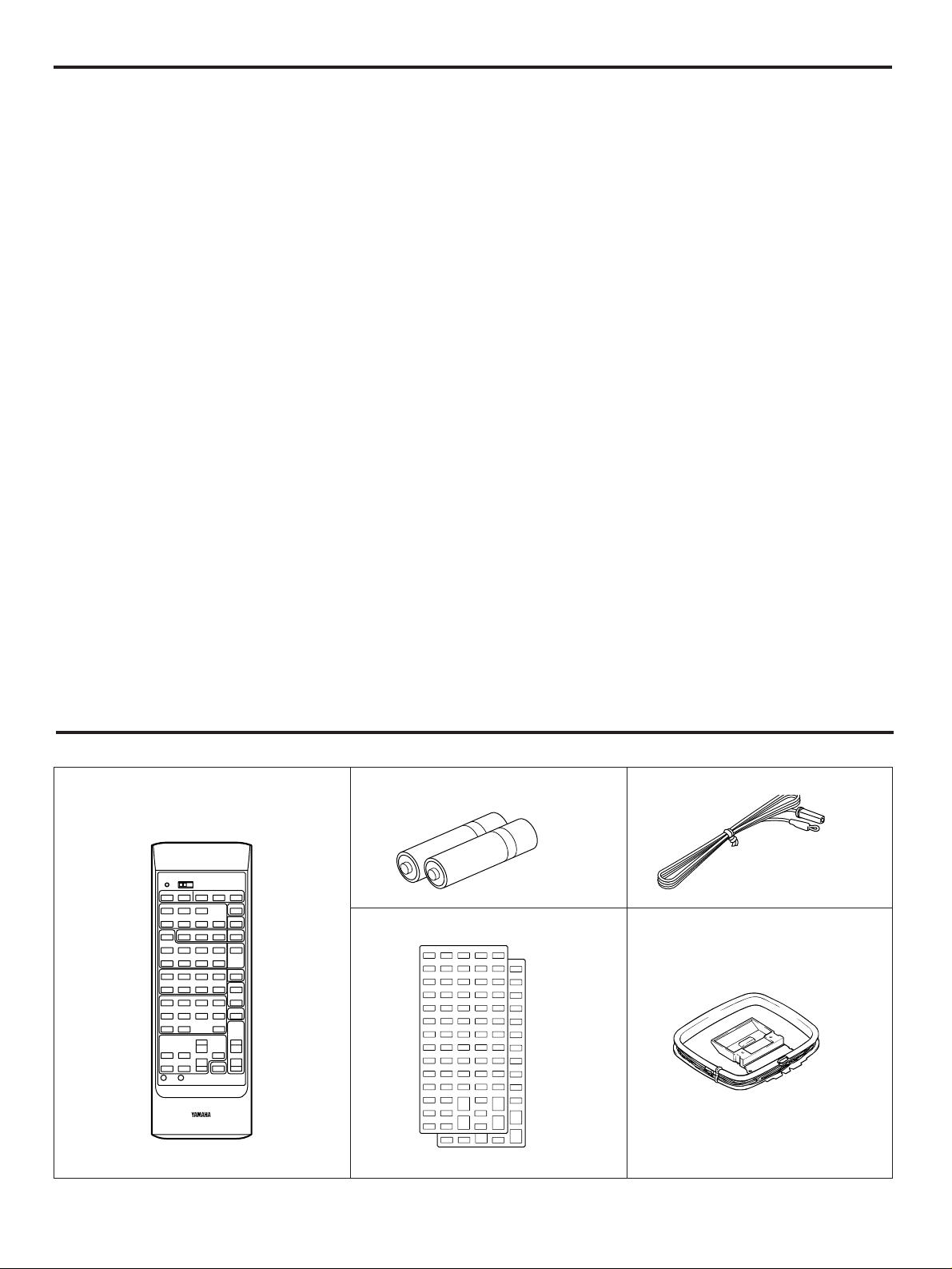
SUPPLIED ACCESSORIES
After unpacking, check that the following parts are contained.
Remote Control Transmitter Batteries (size AA, R6, UM-3)
User Program Sheets
Indoor FM Antenna
AM Loop Antenna
●
5 Speaker Configuration
Front: (U.S.A. and Canada models)
80W + 80W (8Ω) RMS Output
Power, 0.04% THD, 20–20,000 Hz
(Australia, Singapore and
General models)
75W + 75W (8Ω) RMS Output
Power, 0.04% THD, 20–20,000 Hz
Center: (U.S.A. and Canada models)
80W (8Ω) RMS Output
Power, 0.07% THD, 1 kHz
(Australia, Singapore and
General models)
80W (8Ω) RMS Output
Power, 0.07% THD, 1 kHz
Rear: 25W + 25W (8Ω) RMS Output
Power, 0.3% THD, 1 kHz
●
Digital Sound Field Processor (Including
Dolby Pro Logic Surround Decoder)
5 Programs for Audio Sources
5 Programs for Audio/Video Sources
●
Automatic Input Balance Control for
Dolby Surround
●
Test Tone Generator for Easier Speaker
Balance Adjustment
●
3 Center Channel Modes
(NORMAL/WIDE/PHANTOM)
●
40-Station Random Access Preset
Tuning
●
Automatic Preset Tuning
●
Preset Station Shifting Capability (Preset
Editing)
●
IF Count Direct PLL Synthesizer Tuning
System
●
SLEEP Timer
●
Video Signal Input/Output Capability
(Including S Video Connections)
●
Programmable Remote Control
Transmitter
FEATURES
Page 5

5
PROFILE OF THIS UNIT
You are the proud owner of a Yamaha stereo receiver –an extremely sophisticated audio component. The Digital Sound Field
Processor (DSP) built into this unit takes full advantage of Yamaha’s undisputed leadership in the field of digital audio processing to
bring you a whole new world of listening experiences. Follow the instructions in this manual carefully when setting up your system,
and this unit will sonically transform your room into a totally new listening environment – movie theater, concert hall, and so on. In
addition, you get incredible realism from Dolby Surround-encoded video sources using the built-in Dolby Pro Logic Surround
Decoder.
Please read this operation manual carefully and store it in a safe place for later reference.
Digital Sound Field Processing
What is it that makes live music so good? Today’s advanced
sound reproduction technology lets you get extremely close to
the sound of a live performance, but chances are you’ll still
notice something missing: the acoustic environment of the live
concert hall. Extensive research into the exact nature of the
sonic reflections that create the ambience of a large hall has
made it possible for Yamaha engineers to bring you this same
sound in your own listening room, so you’ll feel all the sound of
a live concert.
Furthermore, our technicians, armed with sophisticated
measuring equipment, have even made it possible to capture
the acoustics of a variety of venues such as an actual concert
hall, theater, etc. to allow you to accurately recreate one of
several live performance environments in your own home.
Dolby Pro Logic Surround
The Dolby Pro Logic Surround Decoder program lets you
experience the dramatic realism and impact of a Dolby
Surround movie theater sound in your own home. Dolby Pro
Logic gets its name from its professional-grade steering logic
circuitry, which provides greater effective front and rear
channel separation for a much higher degree of realism than
the “passive” Dolby Surround circuits found in less
sophisticated home audio/video equipment. Dolby Pro Logic
Surround provides a true center channel, so there are four
independent channels, unlike passive Dolby Surround which
has in effect only three channels: left, right, and rear. This
center channel allows listeners seated in even less-than-ideal
positions to hear the dialog originating from action on the
screen while getting a stereo effect as well.
This Dolby Pro Logic Surround Decoder employs a digital
signal processing system. This system increases sound
stability at each channel and minimizes crosstalk between
channels compared to conventional analog Dolby signal
processing.
In addition, this unit features a built-in automatic input balance
control. This circuit always presents you the best surround
conditions without performing manual adjustments.
Dolby Pro Logic Surround + DSP
Additionally you can enjoy sound environment created by the
combination of Dolby Pro Logic and YAMAHA DSP. Precise
sound movement and orientation by the Dolby Pro Logic
technology is added to sound fields which are precisely
recreated on the basis of actual acoustic environments by the
DSP technology, so it is suitable for any Audio/Video source
with video image. This combination is used on sound field
programs “DOLBY PRO LOGIC ENHANCED”, “70 mm MOVIE
THEATER”, “TV THEATER” and “SPORTS”.
The YAMAHA “CINEMA DSP” logo indicates these programs are
created by the combination of Dolby Pro Logic and YAMAHA
DSP technology.
CINEMA DSP
Page 6
6
SPEAKER SETUP
SPEAKERS TO BE USED
This unit is designed to provide the best sound-field quality with a 5 speaker configuration. The most effective speakers to use with
this unit are front speakers, rear speakers and a center speaker. You may omit the center speaker. (Refer to the “4-Speaker
Configuration” shown below.)
The front speakers are used for the main source sound plus the effect sounds. They will probably be the speakers from your
present stereo system. The rear speakers are used for the effect and surround sounds, and the center speaker is for the center
sounds (dialog etc.) within the Dolby Surround encoded programs. The center speaker needs to be equal in power to the front
speakers, although the rear speakers should not be equal. However, all the speakers should have high enough power handling to
accept the maximum output of this unit.
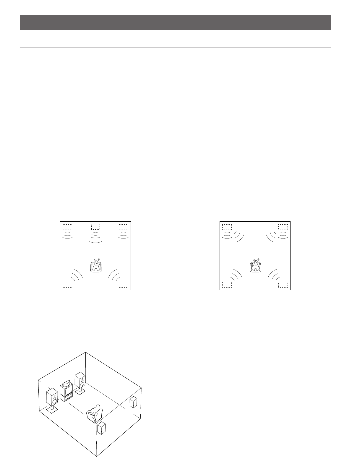
SPEAKER CONFIGURATION
5-Speaker Configuration
This configuration is the most effective and recommended one.
In this configuration, the center speaker is necessary as well as
the rear speakers. If the digital sound field program DOLBY
PRO LOGIC, DOLBY PRO LOGIC ENHANCED, 70 mm
MOVIE THEATER, TV THEATER or SPORTS is selected,
conversations will be output from the center speaker and the
ambience will be excellent.
●
Set the center channel mode to the “NORMAL” or “WIDE”
position. (For details, refer to page 14.)
4-Speaker Configuration
The center speaker is not used in this configuration. If the
digital sound field program DOLBY PRO LOGIC, DOLBY PRO
LOGIC ENHANCED, 70 mm MOVIE THEATER, TV
THEATER or SPORTS is selected, the center sound is output
from the left and the right front speakers. However, the sound
effect of other programs can be the same as that of the 5speaker configuration.
●
Be sure to set the center channel mode to the “PHANTOM”
position. (For details, refer to page 14.)
SPEAKER PLACEMENT
The recommended speaker configuration, the 5-speaker configuration, will require two speaker pairs: front speakers (your normal
stereo speakers), and rear speakers, plus a center speaker. When you place these speakers, refer to the following.
Front: In normal position. (The position of your present
stereo speaker system.)
Rear: Behind your listening position, facing slightly inward.
Nearly six feet (approx. 1.8 m) up from the floor.
Center: Precisely between the front speakers. (To avoid
interference with TV sets, use a magnetically shielded
speaker.)
Front L Center Front R
Dialogue
Surround sound
Dialogue
Surround sound
Rear L
Rear R
Front L Front R
Dialogue
Surround sound
Dialogue
Surround sound
Rear L Rear R
Front R
Center
Front L
TV set
Rear R
Rear L
Page 7
7
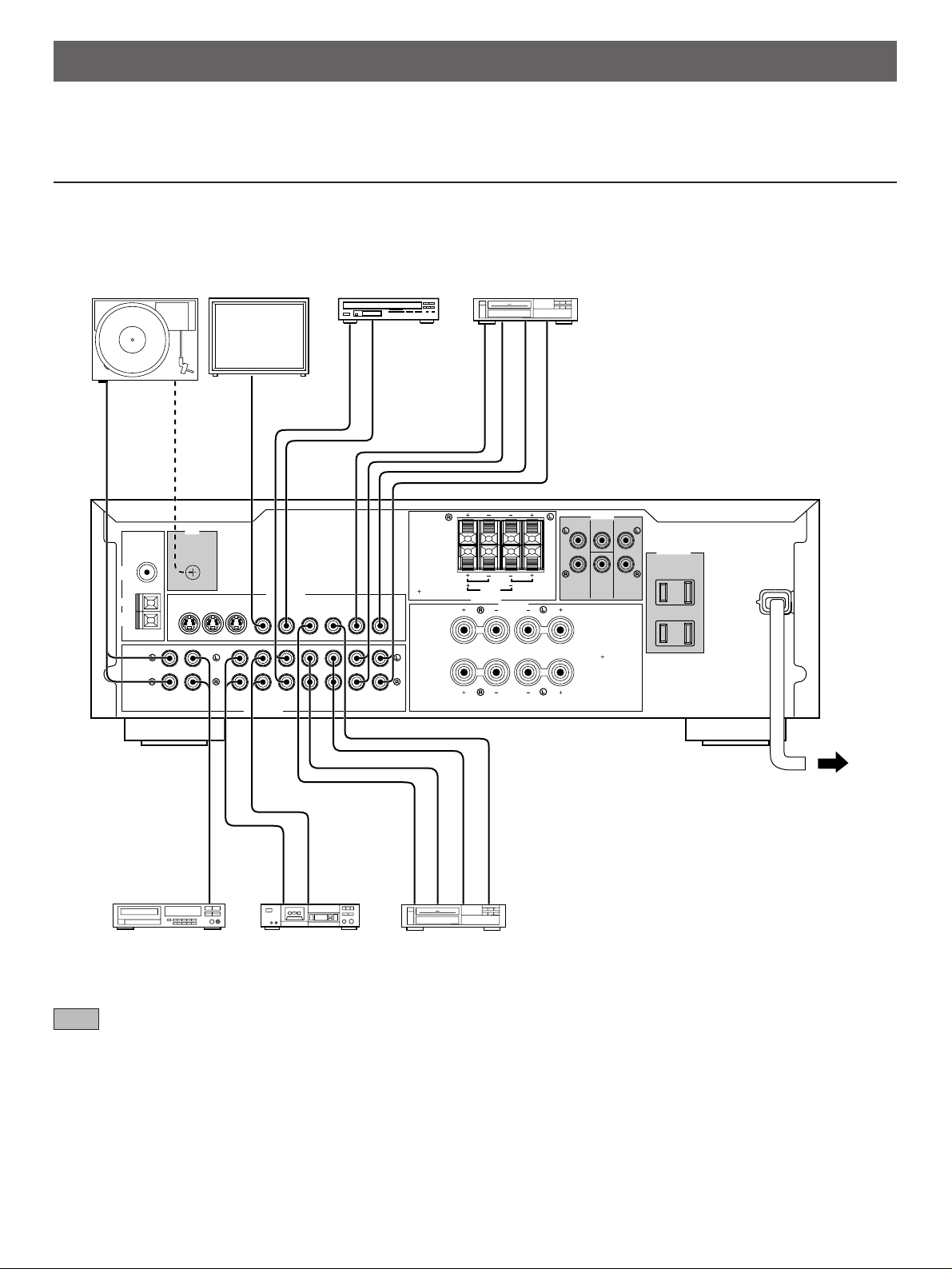
CONNECTIONS
Before attempting to make any connections to or from this unit, be sure to first switch OFF the power to this unit and to any other
components to which connections are being made.
CONNECTIONS WITH OTHER COMPONENTS
When making connections between this unit and other components, be sure all connections are made correctly, that is to say L (left)
to L, R (right) to R, “+” to “+” and “–” to “–”. Also, refer to the owner’s manual for each component to be connected to this unit.
: Refer to “ABOUT THE ACCESSORY TERMINALS” on page 11.
GND
MONITOR
OUT
LD/TV
IN OUT
VCR 1
IN OUT
VCR 2
PHONO CD TAPE LD/TV VCR 1 VCR 2
TAPEPBREC
OUT
IN OUT IN OUT
A OR B:8ΩMIN.
/SPEAKER
A B:l6
Ω
MIN.
/SPEAKER
FRONT
C D:4ΩMIN./SPEAKER
SINGLE:8ΩMIN./SPEAKER
8
Ω
MIN.
/SPEAKER
FRONT CENTER REAR
SWITCHED
I20W MAX. TOTAL
l20W MAX. TOTAL
I.0A MAX. TOTAL
VIDEO SIGNAL
AUDIO SIGNAL
SPEAKERS
SPEAKERS
OUTPUT
AC OUTLETS
A
B
A
B
FM
ANT
AM
ANT
GND
75Ω UNBAL.
fc:200Hz
LOW
PASS
MAINS
OUTPUT
GND
VIDEO IN
AUDIO OUT
VIDEO OUT
VIDEO OUT
AUDIO OUT
VIDEO IN
AUDIO IN
OUTPUT
LINE OUT
LINE IN
VIDEO OUT
AUDIO OUT
AUDIO IN
VIDEO IN
REAR
CENTER
CD
DUAL
SINGLE
MONITOR
OUT
S VIDEO
IN OUT
VCR 2
(U.S.A. model)
To AC outlet
Turntable Monitor TV
LD player,
TV tuner, etc. Video cassette recorder 2
CD player Tape deck Video cassette recorder 1
Page 8
8
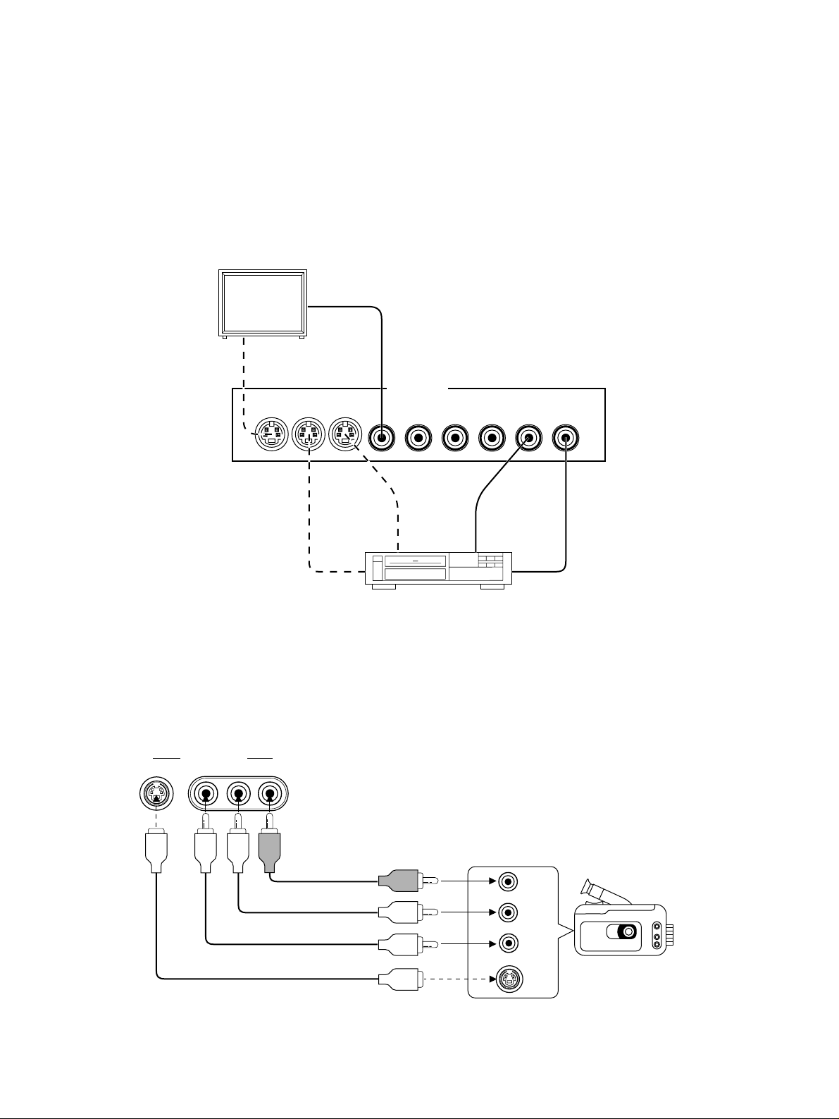
CONNECTING TO S VIDEO TERMINALS
If you have a video cassette recorder and a monitor equipped with “S” (high-resolution) video terminals, those terminals can be
connected to this unit’s S VIDEO terminals. Connect the video cassette recorder’s “S” video input and output terminals to this unit’s
S VIDEO VCR 2 IN and OUT terminals respectively, and connect the monitor’s “S” video input terminal to this unit’s S VIDEO
MONITOR OUT terminal. Otherwise, connect the video cassette recorder’s composite video terminals to this unit’s composite video
terminals, and connect the monitor’s composite video input terminal to this unit’s composite MONITOR OUT terminal.
Note
If video signals are sent to both S VIDEO input and composite input terminals, the signals will be sent to their respective
output terminals independently.
CONNECTING TO VIDEO AUX TERMINALS (ON THE FRONT PANEL)
These terminals are used to connect any video input source such as a camcorder to this unit.
MONITOR
OUT
S VIDEO
IN OUT
VCR 2
MONITOR
OUT
LD/TV
IN OUT
VCR 1
IN OUT
VCR 2
VIDEO SIGNAL
S VIDEO
IN
VIDEO
IN
S VIDEO
OUT
S VIDEO
IN
VIDEO OUT
VIDEO IN
Monitor TV
VIDEO AUX
S VIDEO VIDEO L AUDIO R
S VIDEO
L
R
VIDEO
Video cassette recorder 2
Camcorder
AUDIO OUT R
AUDIO OUT L
VIDEO OUT
S VIDEO OUT
Page 9
9
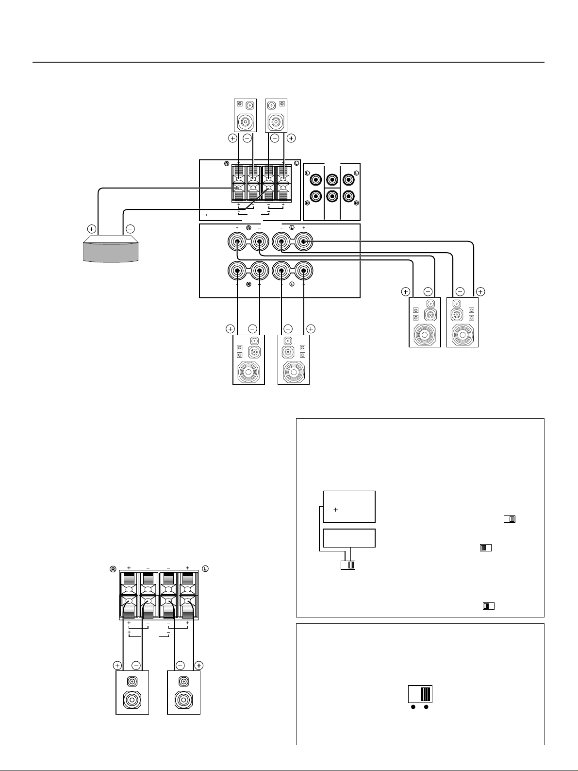
Note on front speaker connection:
One or two speaker systems can be connected to this unit. If
you connect only one speaker system, connect it to either the
SPEAKERS A or B terminals.
Note on center speaker connection:
One or two center speakers can be connected to this unit. If
you cannot place the center speaker on or under the TV, it is
recommended to use two center speakers and place them on
both sides of the TV to orient the center sound at the center
position.
For connecting two center speakers, follow the method shown
below.
IMPEDANCE SELECTOR switch
(Canada model only)
Be sure to switch this only when the power of this unit is
turned off. Select the position proper for the use of your front
speakers.
When using one pair of front
speakers;
•
If the impedance of each speaker is
8Ω or higher, set to right ( ).
•
If the impedance of each
speaker is 4Ω or higher, but lower
than 8Ω, set to left ( ).
When using two pairs of front
speakers;
The impedance of each speaker must
be 8Ω or higher.
Set this switch to left ( ).
FRONT LEVEL switch
(Australia and Singapore models only)
Normally set to “0 dB”. If desired, you can decrease the
output level at the FRONT SPEAKERS terminals by 10 dB by
setting this switch to “–10 dB”. (Refer to “Notes” on page 15.)
CONNECTING SPEAKERS
FRONT
C D:4ΩMIN./SPEAKER
SINGLE:8ΩMIN./SPEAKER
8
Ω
MIN.
/SPEAKER
REAR
CENTER
FRONT CENTER REAR
SPEAKERS
SPEAKERS
OUTPUT
A
B
A
B
fc:200Hz
LOW
PASS
CD
DUAL
SINGLE
Connect the respective speakers to this unit as figured below.
Rear speakers
Center speaker
Front speakers B
Left
Right
Left
Right
Center speaker
Center speaker
Front speakers A
Left
Right
A OR B:USE 4ΩMIN.
/SPEAKER
A
B:USE 8ΩMIN.
/SPEAKER
A
OR
B:USE 8ΩMIN.
/SPEAKER
IMPEDANCE
SELECTOR
SELECTEUR
D’IMPEDANCE
REAR
CENTER
CD
DUAL
SINGLE
l
l0 dB 0 dB
FRONT
LEVEL
Page 10
10
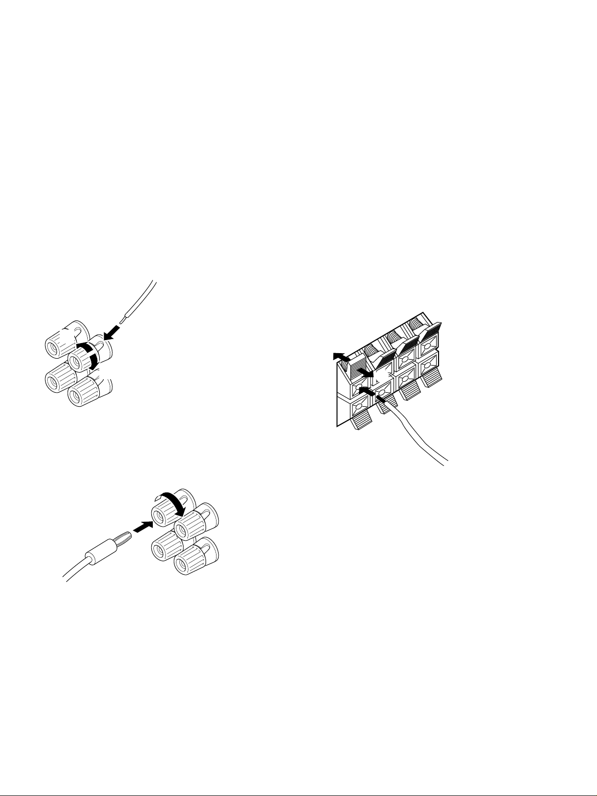
How to Connect:
Connect the SPEAKERS terminals to your speakers with wire
of the proper gauge, cut as short as possible. If the
connections are faulty, no sound will be heard from the
speakers. Make sure that the polarity of the speaker wires is
correct, that is, + and – markings are observed. If these wires
are reversed, the sound will be unnatural and will lack bass.
Do not let the bare speaker wires touch each other and do
not let them touch the metal parts of this unit as this could
damage this unit and/or speakers.
Note
Use speakers with the specified impedance shown on the rear
of this unit.
For connecting to the FRONT SPEAKERS terminals
Red: positive (+)
Black: negative (–)
➀
Unscrew the knob.
➁
Insert the bare wire.
[Remove approx. 5mm
(1/4”) insulation from
the speaker wires.]
➂
Tighten the knob and
secure the wire.
*
<For U.S.A., Canada and General models only>
Banana Plug connections are also possible. Simply insert
the Banana Plug connector into the corresponding terminal.
For connecting to the REAR and CENTER SPEAKERS
terminals
Red: positive (+)
Black: negative (–)
➀
Press up the tab.
➁
Insert the bare wire.
[Remove approx. 5mm
(1/4”) insulation from
the speaker wires.]
➂
Release the tab and
secure the wire.
➁
➂
➀
1
2
3
Page 11
11
Subwoofer system
ABOUT THE ACCESSORY TERMINALS
AC OUTLET(S) (SWITCHED)
(U.S.A., Canada, Singapore and General models)
...........................................................2 SWITCHED OUTLETS
(Australia model) ................................. 1 SWITCHED OUTLET
Use these to connect the power cords from your components
to this unit.
The power to the SWITCHED outlets is controlled by this unit’s
POWER switch or the provided remote control transmitter’s
POWER key. These outlets will supply power to any
component whenever this unit is turned on.
The maximum power (total power consumption of
components) that can be connected to the SWITCHED AC
OUTLET(S) is as follows.
......................................................................................... 120W
GND terminal (For turntable use)
Connecting the ground wire of the turntable to this terminal will
normally minimize hum, but in some cases better results may
be obtained with the ground wire disconnected.
LOW PASS terminal
This terminal is for output to a monaural amplifier driving a
subwoofer. Only frequencies below 200 Hz from the front and
center channels are output.
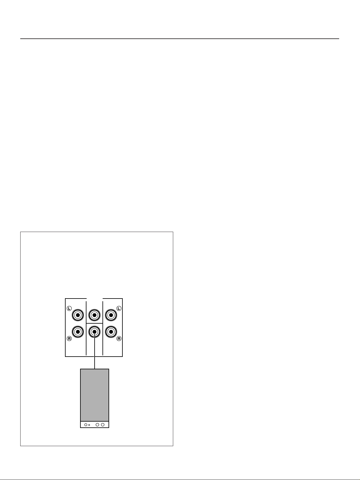
ADDING A SUBWOOFER
You may wish to add a subwoofer to reinforce the bass
frequencies.
Connect the LOW PASS terminal to the INPUT terminal of
the subwoofer amplifier, and connect the speaker terminals
of the subwoofer amplifier to the subwoofer.
With some subwoofers, including the Yamaha Active Servo
Processing Subwoofer System, the amplifier and subwoofer
are in the same unit.
FRONT OUTPUT terminals
These terminals are for front channel line output. There is no
connection to these terminals when you use the built-in
amplifier.
However, if you drive front speakers with an external stereo
power amplifier, connect the input terminals of the external
amplifier (MAIN IN or AUX terminals of a power amplifier or an
integrated amplifier) to these terminals.
REAR OUTPUT terminals
These terminals are for rear channel line output. There is no
connection to these terminals when you use the built-in
amplifier.
However, if you drive rear speakers with an external stereo
power amplifier, connect the input terminals of the external
amplifier (MAIN IN or AUX terminals of a power amplifier or an
integrated amplifier) to these terminals.
CENTER OUTPUT terminal
This terminal is for center channel line output. There is no
connection to this terminal when you use the built-in amplifier.
However, if you drive a center speaker with an external power
amplifier, connect the input terminal of the external amplifier to
this terminal.
OUTPUT
FRONT CENTER REAR
LOW
PASS
fc:200Hz
Page 12
12
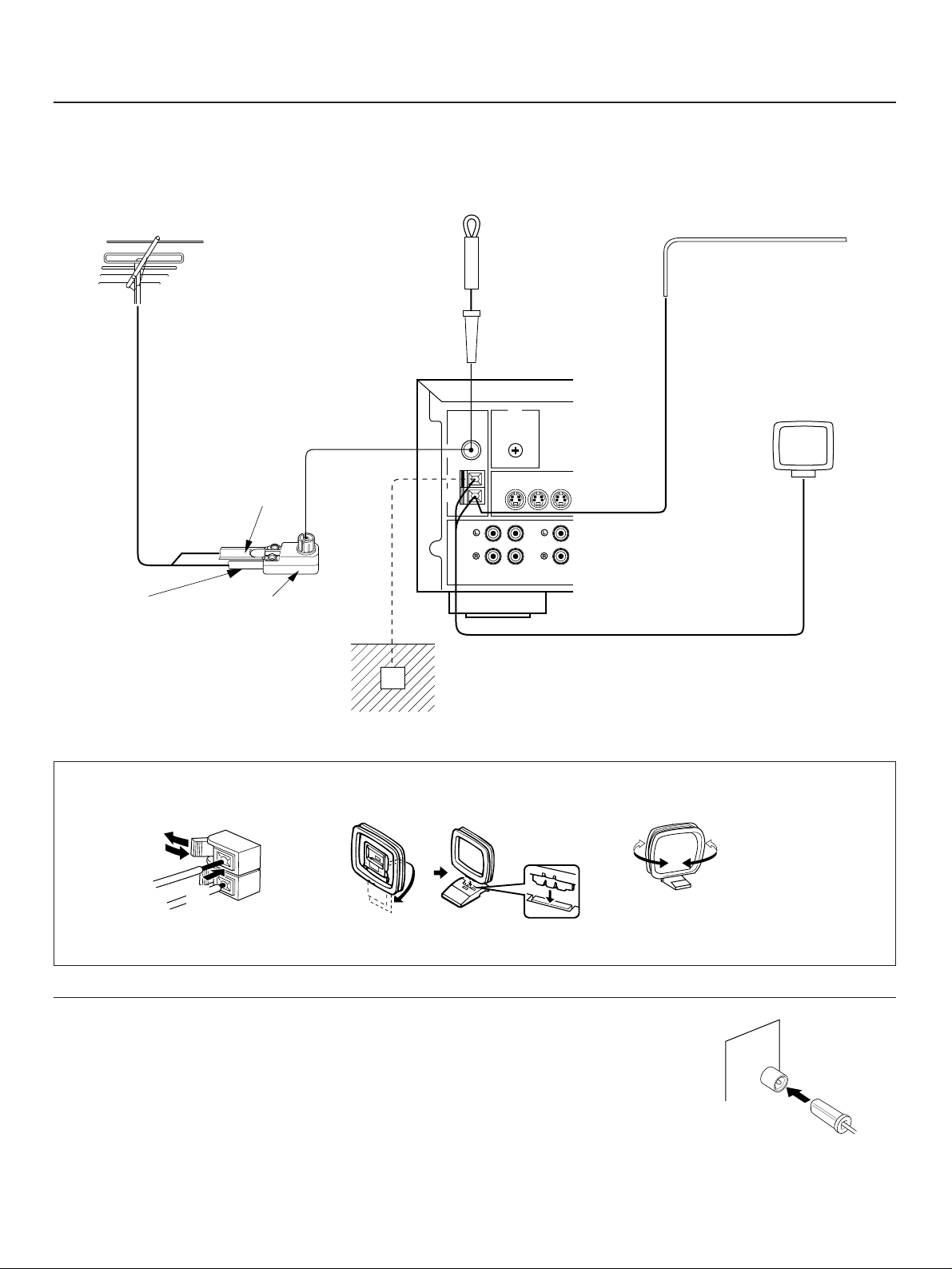
ANTENNA CONNECTIONS
●
Each antenna should be connected to the designated terminals correctly, referring to the following diagram.
●
Both AM and FM indoor antennas are included with this unit. In general, these antennas will probably provide sufficient signal
strength. Nevertheless, a properly installed outdoor antenna will give clearer reception than an indoor one. If you experience
poor reception quality, an outdoor antenna may result in improvement.
Connecting the AM loop antenna
* The AM loop antenna should be placed apart from the main unit. The antenna may be hung on a wall.
* The AM loop antenna should be kept connected, even if an outdoor AM antenna is connected to this unit.
GND terminal
For maximum safety and minimum interference, connect the
GND terminal to a good earth ground. A good earth ground is
a metal stake driven into moist earth.
Notes
●
When connecting the indoor
FM antenna, insert its
connector into the FM ANT
terminal firmly.
●
If you need an outdoor
FM antenna to improve
FM reception quality, either 300-ohm feeder or coaxial cable
may be used. In locations troubled by electrical
interference, coaxial cable is preferable.
Outdoor FM antenna
Outdoor AM antenna
AM loop
antenna
(included)
Ground
Indoor FM
antenna
(included)
75-ohm/300-ohm
antenna adapter
75-ohm
coaxial cable
300-ohm
feeder
GND
MONITOR
OUT
S VIDEO
IN OUT
VCR 2
PHONO CD
TAPE
PB
FM
ANT
AM
ANT
GND
75Ω UNBAL.
➀
➁
➂
Orient so that the best
reception is obtained.
12 3
Page 13
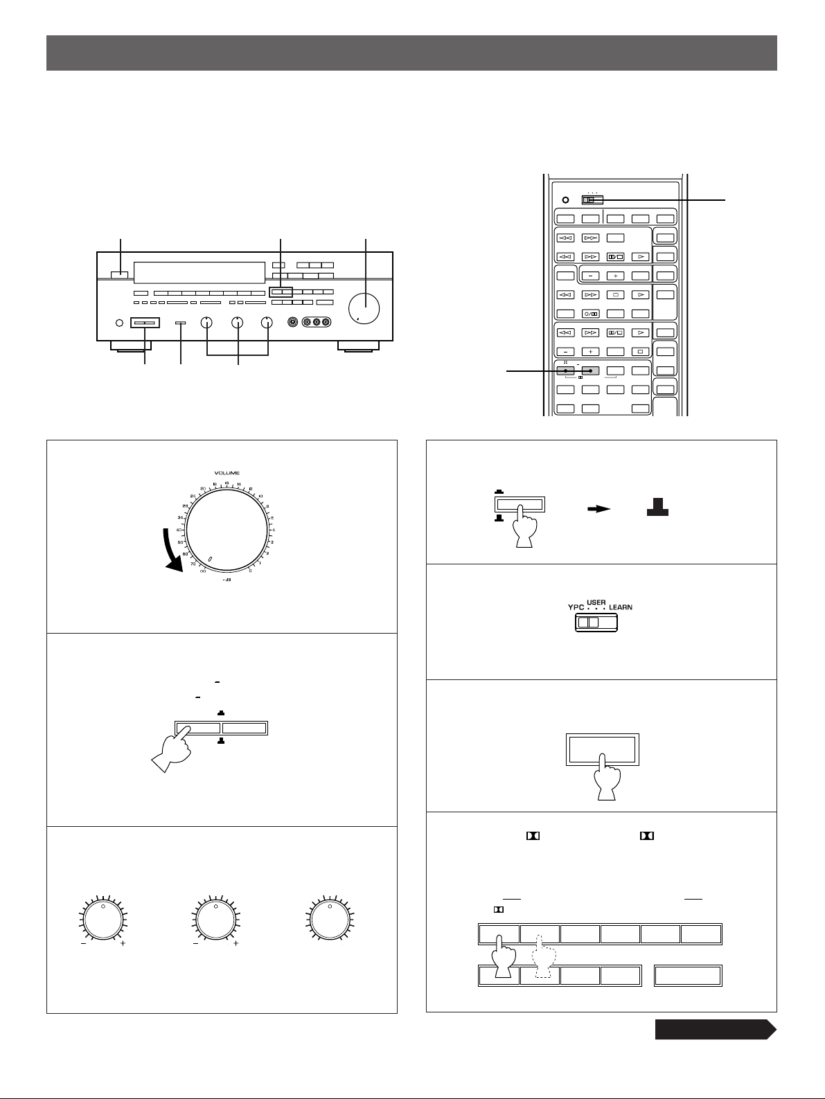
1
Set to the “ ∞” position.
2 Select the front speakers to be used.
* If you use two front speaker systems, press both the A
and B switches.
3
Set to the “0” position.
4
5
Set to
“YPC”.
6 Turn the power on.
7 Select the PRO LOGIC or PRO LOGIC
ENHANCED mode, so that the corresponding name is
illuminated on the display.
13
SPEAKER BALANCE ADJUSTMENT
This procedure lets you adjust the sound output level balance between the front, center, and rear speakers using the built-in test
tone generator. When this adjustment is performed, the sound output level heard at the listening position will be the same from
each speaker. This is important for the best performance of the digital sound field processor.
The adjustment of each speaker output level should be done at your listening position with the remote control transmitter.
Otherwise, the result may not be satisfactory.
7
1
6
2
4
3
SPEAKERS
A
B
ON
OFF
ON
OFF
BASS
55
4
3
2
l0l
2
3
4
TREBLE
55
4
3
2
l0l
2
3
4
BALANCE
55
4
3
2
l0l
2
3
4
LR
POWER
OFF
CONTINUED
TRANSMIT
USER
YPC
LEARN
POWER SLEEP TV VCR AUX
SKIP
PAUSE/STOP
SEARCH
DECK A/B
PRESET
REC/PAUSE
DIR A DIR B
PAUSE/STOP
SEARCH
CHAPTER/CH DISPLAY STOP VCR 1
70mm
ENHANCEDPRO LOGIC
SURROUND
HALLCHURCH
MOVIE THEATER
DSP
1234
5678
910
DISC
SKIP
A/B/C/D/E
PLAYSTOPSEARCH
TV
THEATER
EFFECT
ON/OFF
PHONO
TUNER
TAPE MON
LD/TVPLAY
VCR 2
V–AUXJAZZ CLUBROCKSTADIUMSPORTS
MASTER
VOLUME
5
CDPLAY
/LEARN
REC MUTE
7
TONE
BYPASS
ON
OFF
PRO LOGIC
ROCK
CONCERT
JAZZ CLUB
DIGITAL SOUND FIELD PROCESSOR
ENHANCED
70mm
MOVIE THEATER
CHURCH
TV
THEATER
CONCERT
HALL
SPORTS
EFFECT
STADIUM
Page 14
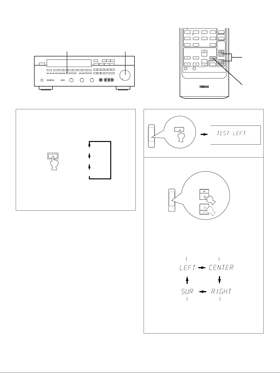
14
CHAPTER/CH DISPLAY STOP VCR 1
VCR 2
TV
THEATER
70mm
MOVIE THEATER
ENHANCEDPRO LOGIC
V–AUXJAZZ CLUBROCKSTADIUMSPORTS
SURROUND
DSP
EFFECT
ON/OFF
MASTER
VOLUME
CENTER LEVEL
REAR LEVEL
DELAY
TIME
TEST
RESET CLEAR
1234
5678
MUTING
HALLCHURCH
910
10
9
8 Select the center channel output mode according to your
speaker configuration.
(Refer to “SPEAKER CONFIGURATION” on page 6.)
On the feature of each mode, refer to the “Note” shown
below.
9
10 Turn up the volume.
You will hear a test tone (like pink noise) from the left front
speaker, then the center speaker, then the right front
speaker, and then the rear speakers, for about two
seconds each. The display changes as shown below.
* The test tone from the left rear speaker and the right rear
speaker will be heard at the same time.
Note
In step 8, when you select the center channel output mode,
note the following.
For 5 speaker configuration)
NORMAL: Select this mode when you use a center speaker
that is smaller than the front speakers. In this
mode, the bass tone will be output from the front
speakers.
WIDE: Select this mode when you use the center speaker
approximately same sized as the front speakers.
For 4 speaker configuration)
PHANTOM: Select this mode when you do not use the center
speaker. The center sound will be output from the
left and right front speakers.
MASTER
VOLUME
CENTER
MODE
TEST
NORMAL
WIDE
PHANTOM
Front (L)
Rear
(L and R)
Center
Front (R)
108
Page 15
15
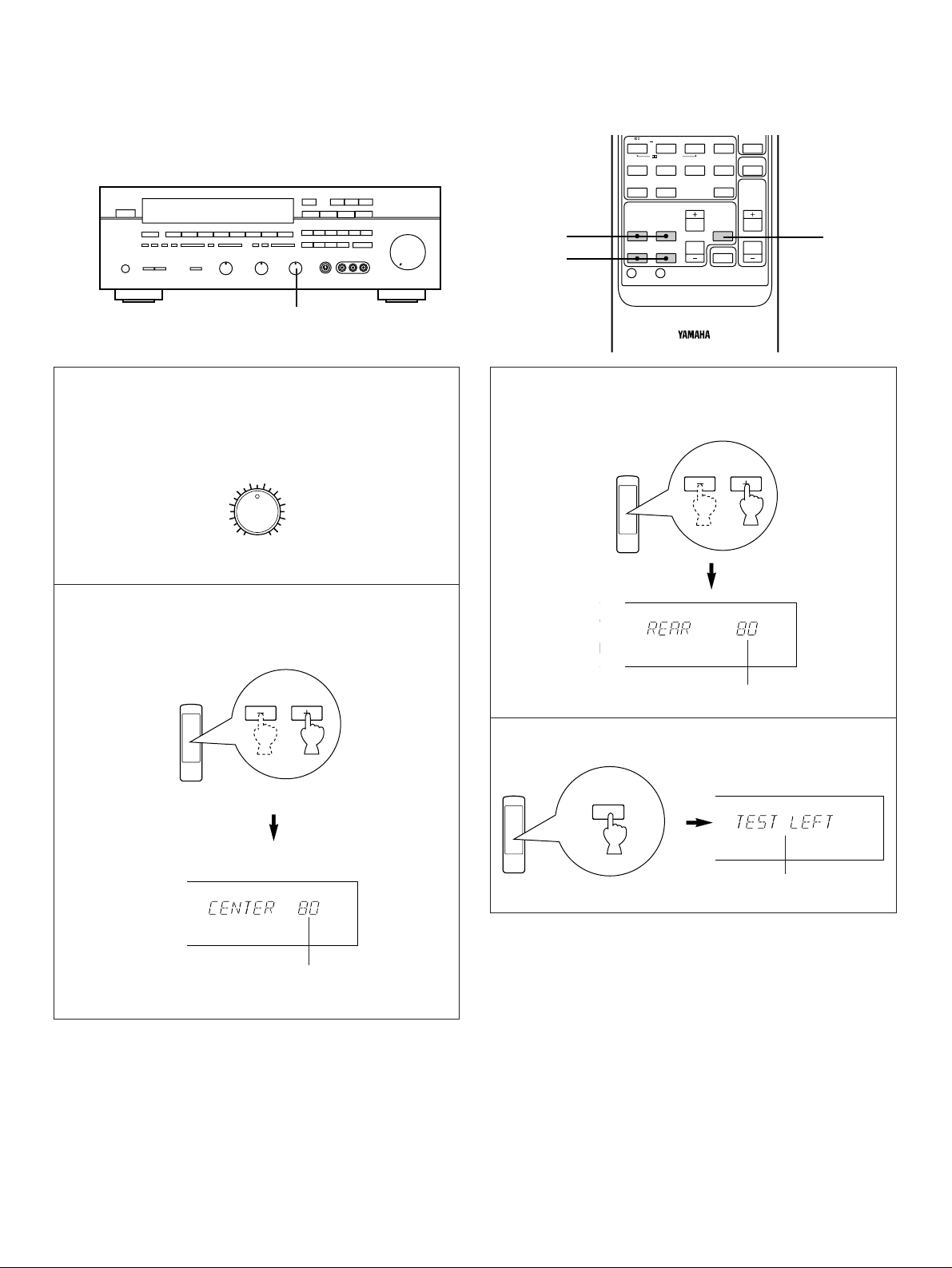
11 Adjust the BALANCE control so that the effect sound
output level of the left front speaker and the right front
speaker are the same.
12 Adjust the sound output level of the center speaker to
be at the same level as that of the front speakers with
the CENTER LEVEL keys.
13 Adjust the sound output level of the rear speakers to
be at the same level as that of the front speakers with
the REAR LEVEL keys.
14 Cancel the test tone.
Disappears
Notes
●
Once you have completed these adjustments, you can
adjust whole sound level on your audio system by using
the VOLUME control (or the MASTER VOLUME keys on
the remote control transmitter).
●
If you use external power amplifiers, their volume controls
may also be adjusted to achieve proper balance.
●
In step 12, if the center channel mode is in the
“PHANTOM” position, the sound output level of the center
speaker cannot be adjusted. This is because in this mode,
the center sound is automatically output from the left and
right front speakers.
●
<Australia and Singapore models only>
If there is insufficient sound output from the center and
rear speakers, you may decrease the front speaker output
level by setting the FRONT LEVEL switch on the rear
panel to “–10 dB”.
11
CENTER LEVEL
REAR LEVEL
l00
TEST
Adjustable
Adjustable
VCR 2
TV
THEATER
70mm
MOVIE THEATER
ENHANCEDPRO LOGIC
V–AUXJAZZ CLUBROCKSTADIUMSPORTS
SURROUND
DSP
EFFECT
ON/OFF
MASTER
VOLUME
CENTER LEVEL
REAR LEVEL
DELAY
TIME
TEST
RESET CLEAR
1234
5678
MUTING
HALLCHURCH
910
12
13
14
BALANCE
l0l
2
3
4
LR
2
3
4
55
Page 16
16
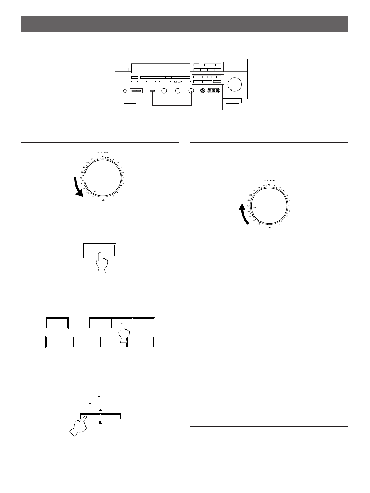
1
Set to the “ ∞” position.
2 Turn the power on.
3 Select the desired input source by using the input
selector buttons.
(For video sources, turn the TV/monitor ON.)
* The name of the selected input source will appear in
the display.
4 Select the front speakers to be used.
* If you use two front speaker systems, press both the A and
B switches.
5 Play the source. (For detailed information on the
tuning operation, refer to page 19.)
6
Adjust to the desired output level.
7 If desired, adjust the BASS, TREBLE, BALANCE
controls, etc. (refer to page 18) and use the digital
sound field processor. (Refer to page 25.)
Notes on using the input selector buttons
●
Note that pressing on each input selector button selects
the source which is connected to the corresponding input
terminals on the rear panel.
* To select the source connected to the VIDEO AUX
terminals on the front panel, press VIDEO AUX.
●
The selection of TAPE MONITOR cannot be canceled by
pressing another input selector button. To cancel it, press
TAPE MONITOR again.
When you select a button other than TAPE MONITOR,
make sure that TAPE MONITOR is not also selected.
●
If you select the input selector button for a video source
without canceling the selection of TAPE MONITOR, the
playback result will be the video image from the video
source and the sound from the audio tape.
●
Once you play a video source, its video image will not be
interrupted even if the input selector button for an audio
source is selected.
To turn off the power
Press the POWER switch again.
BASIC OPERATIONS
TO PLAY A SOURCE
SPEAKERS
A
B
ON
OFF
ON
OFF
VIDEO AUX
VCR 2 VCR 1
LD/TV
TUNER CD PHONO
TAPE
MONITOR
3
1, 6
2
4
7
7
POWER
Page 17
17
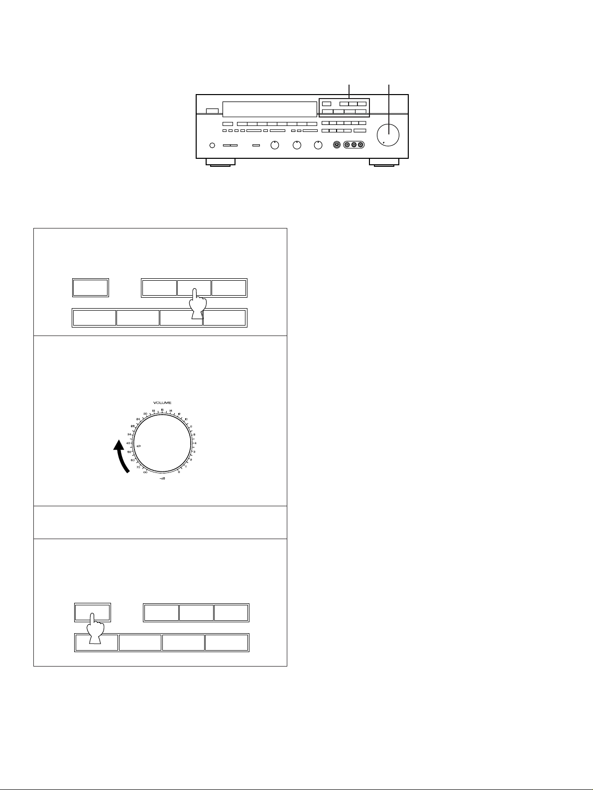
1 Select the source to be recorded.
2
Play the source and then turn the VOLUME control
up to confirm the input source. (For detailed information
on the tuning operations, refer to page 19.)
3 Set the tape deck or VCR to the recording mode.
4 If the tape deck is used for recording, you can monitor
the sounds being recorded by pressing TAPE
MONITOR.
Note
DSP, VOLUME, BASS, TREBLE and BALANCE control
settings have no effect on the material being recorded.
TO RECORD A SOURCE TO TAPE
(OR DUB FROM TAPE TO TAPE)
VIDEO AUX
VCR 2 VCR 1
LD/TV
TUNER CD PHONO
TAPE
MONITOR
VIDEO AUX
VCR 2 VCR 1
LD/TV
TUNER CD PHONO
TAPE
MONITOR
1, 4
2
Page 18
18
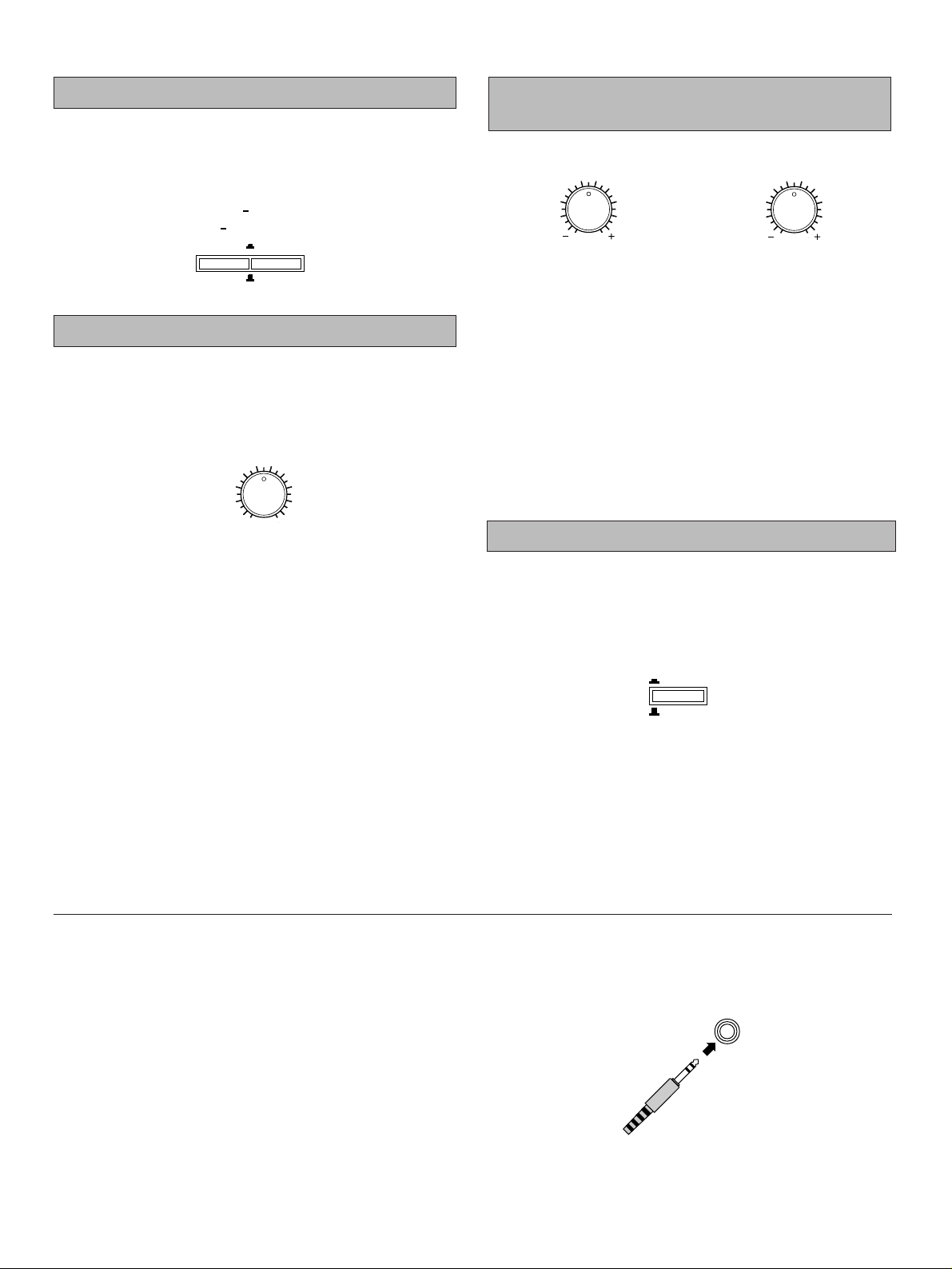
Because one or two speaker systems (as front speakers) can
be connected to this unit, the SPEAKERS switches allow you
to select speaker system A or B, or both at once.
Adjust the balance of the output volume to the left and right
speakers to compensate for sound imbalance caused by
speaker location or listening room conditions.
Note
This control is effective only for the sound from the front
speakers.
BASS : Turn this clockwise to increase (or counter-
clockwise to decrease) the low frequency
response.
TREBLE : Turn this clockwise to increase (or counter-
clockwise to decrease) the high frequency
response.
Note
These controls are effective only for the sound from the front
speakers.
Press this switch to revert instantly to the flat states of the
BASS and TREBLE controls without changing the setting of
these controls.
When you listen with headphones
Connect the headphones to the PHONES jack. You can listen
to the sound to be output from the front speakers through
headphones.
When listening with headphones privately, set both the
SPEAKERS A and B switches to the OFF position and switch
off the digital sound field processor (so that no DSP program
name is illuminated on the display) by pressing the EFFECT
switch.
Selecting the SPEAKER system
Adjusting the BASS and TREBLE
controls
Adjusting the BALANCE control
Using the TONE BYPASS switch
SPEAKERS
A
ON
B
ON
BASS
l0l
2
3
4
55
2
3
4
TREBLE
l0l
2
3
4
55
2
3
4
OFF
OFF
BALANCE
l0l
2
3
4
LR
2
3
4
55
TONE
BYPASS
ON
OFF
PHONES
Page 19
19
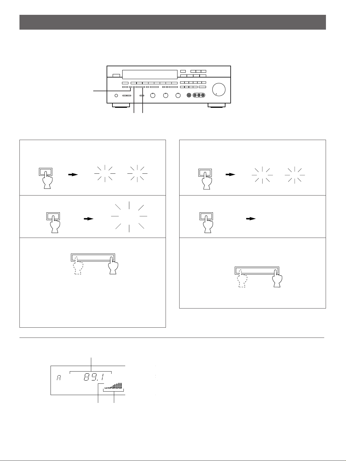
1 Select the reception band (FM or AM) while watching
the display.
2
3 Tune to a desired station manually.
* To continue tuning search, press and hold the button.
FM/AM
FM AM
or
1 Select the reception band (FM or AM) while watching
the display.
2
3
To tune to a higher frequency, press the right side once.
To tune to a lower frequency, press the left side once.
* If the station where tuning search stops is not the desired
one, press again.
* If the tuning search does not stop at the desired station
(because the signals of the station are weak), change to
the MANUAL TUNING method.
TUNING OPERATIONS
Normally, if station signals are strong and there is no interference, quick automatic-search tuning (AUTOMATIC TUNING) is
possible. However, if signals of the station you want to select are weak, you must tune to it manually (MANUAL TUNING).
Display information
➀
Displays the band and frequency of the received station.
➁
Lights up when an FM stereo broadcast is received in
stereo.
➂
Indicates the signal level of the received station.
Note
If you tune to an FM station manually, it is received in
monaural mode automatically to increase the signal quality.
AUTOMATIC TUNING MANUAL TUNING
FM/AM
TUNING
MODE
AUTO/MAN’L MONO
TUNING
MODE
AUTO/MAN’L MONO
DOWN
TUNING UP
DOWN
TUNING UP
PRESET
MHz
FM
STEREO
0
20
l00
40 60
➀
➁
➂
AUTO
TUNING
“AUTO TUNING”
goes off.
FM AM
or
1 3
2
Page 20
20
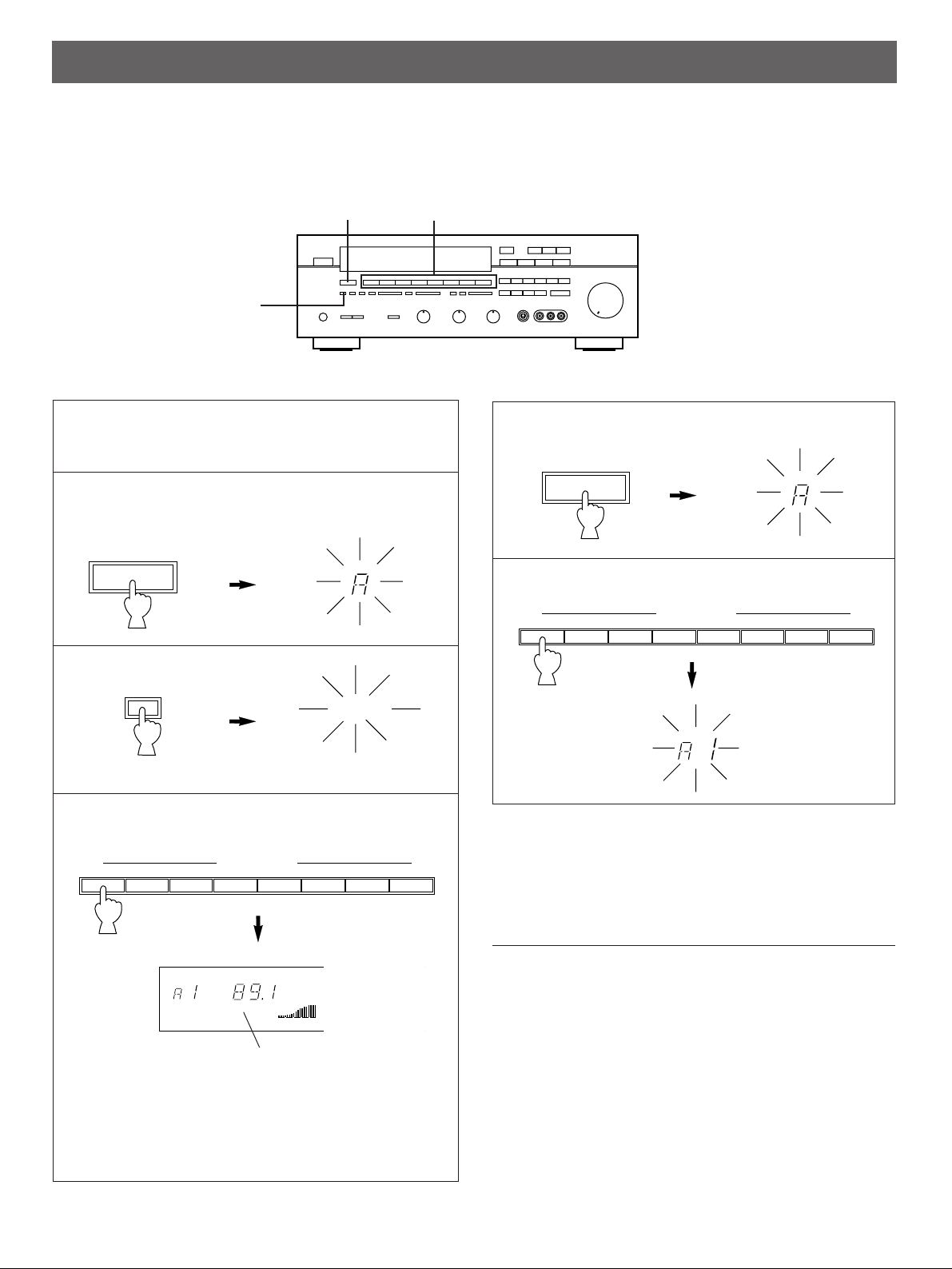
1 Tune to a desired station.
(Refer to the previous page for tuning procedure.)
2 Select a desired page (A – E) of preset station buttons
while watching the display.
3
4 Press a preset station button before “MEMORY”
goes off from the display.
* In the same way, program other stations to A2, A3 ... A8.
* You can program more stations to the preset station
buttons on other pages in the same way by selecting
other pages in step 2.
11 Select the page of preset station buttons.
22 Select the desired preset station button.
Notes
●
A new setting can be programmed in place of the former
one.
●
For presets, the setting of the reception mode (stereo or
monaural) is stored along with the station frequency.
Memory back-up
The memory back-up circuit prevents the programmed data
from being lost even if the POWER switch is set off or the
power plug is disconnected from the AC outlet or the power is
cut due to temporary power failure. If, however, the power is
cut for more than one week, the memory may be erased. If
so, it can be re-programmed by simply following the PRESET
TUNING steps.
MANUAL PRESET TUNING
This unit can store station frequencies (selected by tuning operation) by using the preset station buttons. With this function, you can
select any desired station by only pressing the corresponding preset station button. Up to 40 stations (8 stations x 5 pages) can be
stored.
PRESET TUNING
To store stations
To recall a preset station
3
2, 11
4, 22 (Preset station buttons)
A/B/C/D/E
PRESET
MEMORY
MAN’L/AUTO FM
MEMORY
A/B/C/D/E
PRESET
Flashes on and off
for about 5 seconds.
l 2345 678
PRESET STATIONS
l 2345 678
PRESET STATIONS
PRESET
MHz
FM
STEREO
0
20
l00
40 60
AUTO
TUNING
Shows the displayed station has been
programmed to A1.
PRESET
Page 21
1
2
3
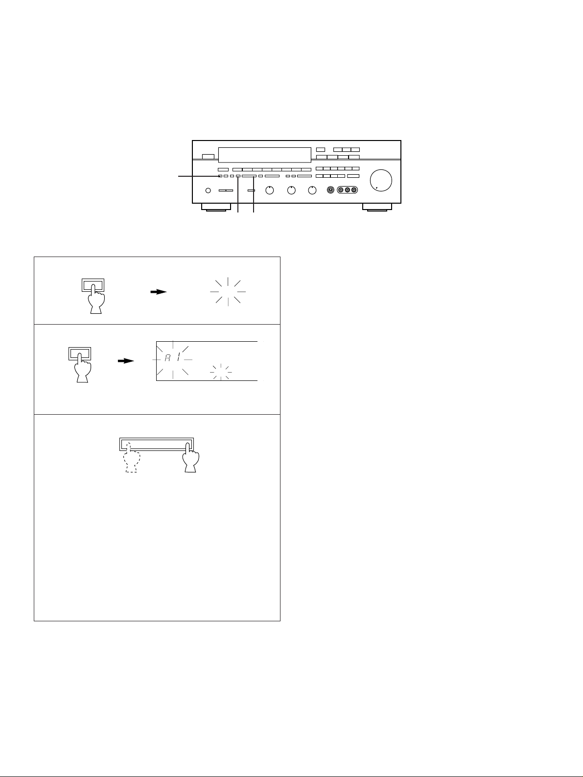
To tune to higher frequencies, press right side once.
To tune to lower frequencies, press left side once.
* If the TUNING button is not pressed, in a while, the
automatic preset tuning begins automatically toward higher
frequencies.
The automatic preset tuning begins from the frequency
currently displayed. Received stations are programmed to
A1, A2 ... A8 sequentially.
* If more than 8 stations are received, they are also
programmed to the preset station numbers on other pages
(B, C, D and E) in that order.
If you want to store the first station received by the
automatic preset tuning to a desired preset station
number.
If, for example, you want to store the first received station to
C5, select “C5” by using the A/B/C/D/E button and the preset
station buttons after pressing the MEMORY button in step 2.
Then press the TUNING button. The first received station is
stored to C5, and next stations to C6, C7 ... sequentially.
If stations are stored up to E8, the automatic preset tuning is
finished automatically.
When the automatic preset tuning is finished
The display shows the frequency of the last preset station.
Check the contents and the number of preset stations by
following the procedure of the section “To recall a preset
station” on page 20.
To recall a preset station
Simply follow the procedure of the section “To recall a preset
station” on page 20.
Notes
●
You can replace a preset station by another FM or AM
station manually by simply following the procedure of the
section “To store stations” on page 20.
●
If the number of received stations is not enough to be stored
up to E8, the search is finished automatically when it
reaches the highest frequency after searching through all
frequencies.
●
With this function, only FM stations with sufficient signal
strength are stored automatically. If the station you want to
program is weak in signal strength, tune to it in monaural
manually and program it by following the procedure of the
section “To store stations” on page 20.
21
AUTOMATIC PRESET TUNING
You can also make use of an automatic preset tuning function for FM stations only. By this function, this unit performs automatic
tuning and stores FM stations with strong signals sequentially. Up to 40 stations are stored automatically in the same way as in the
manual preset tuning method on page 20.
FM/AM
FM
MEMORY
MAN’L/AUTO FM
To store stations
Press and hold for
about 3 seconds.
Flashes.
2
1 3
DOWN
TUNING UP
PRESET
MEMORY
AUTO
TUNING
Page 22
22
EXCHANGING PRESET STATIONS
You can exchange the places of two preset stations with each other as shown below.
Example)
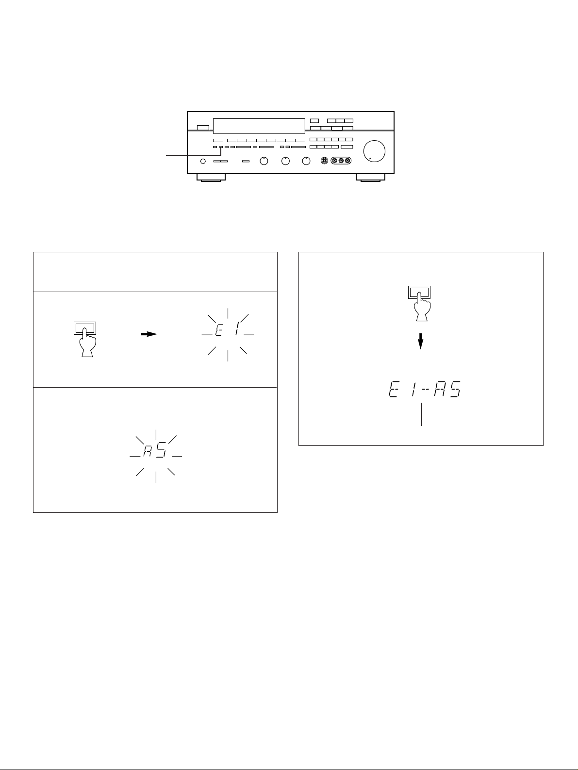
If you want to shift the preset station on E1 to A5, and vice
versa.
1 Recall the preset station on E1 (by following the method
of “To recall a preset station” on page 20).
2
3 Next, recall the preset station on A5 by following the
same method with step 1.
4
Shows the exchange of stations is completed.
Flashes
Flashes
EDIT
EDIT
MEMORY
MEMORY
2, 4
Page 23
23
USING DIGITAL SOUND FIELD PROCESSOR (DSP)
This unit incorporates a sophisticated, multi-program digital sound field processor, which allows you to expand and shape the audio
sound field from both the audio and video sources, for a theater-like experience in the listening/viewing room.
This digital sound field processor has 10 programs; 5 programs for audio sources and 5 programs for Audio/Video sources. You can
create an excellent audio sound field by selecting the suitable program and adding desired adjustments. In addition, when the
DOLBY PRO LOGIC, DOLBY PRO LOGIC ENHANCED or 70 mm MOVIE THEATER program is selected, the built-in automatic
input balance control functions. This presents you the best surround condition without manual adjustment.
DELAY TIME CENTER REAR
CENTER
MODE
JAZZ CLUB
ROCK
CONCERT
CONCERT
HALL
PRO LOGIC
ENHANCED
TV
THEATER
SPORTS
STADIUM
DIGITAL SOUND FIELD PROCESSOR
VIDEO AUX
VCR 2 VCR 1
LD/TV
TAPE
MONITOR
TUNER CD PHONO
EFFECT
45678
PRESET STATIONS
CINEMA DSP
LEVEL
MOVIE THEATER
70mm
CHURCH
kHz
MHz
SLEEP
STEREO
0
20
l00
NORMAL WIDEPHANTOM
40 60
DSP
PRO LOGIC
70 mm
ENHANCED
1
23 4 5 6
Front Panel
Remote Control Transmitter
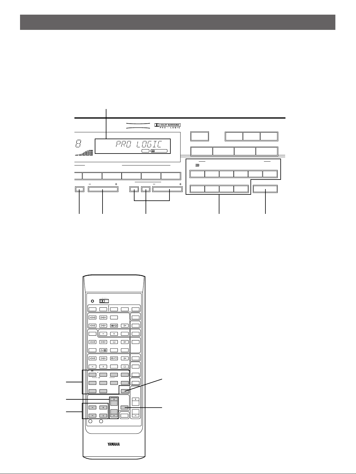
1 Displays your selection on the DSP or
other information.
2 CENTER MODE
Selects the center channel output mode.
(For details, refer to page 14.)
3 DELAY TIME –/+
Adjusts the delay time. (For details, refer
to page 27.)
4 CENTER LEVEL –/+
REAR LEVEL –/+
Adjusts sound output level at each
speaker.
(For details, refer to page 26.)
5 Selects a digital sound field program.
6 EFFECT
Switches on/off the digital sound field
processor (DSP).
7 TEST
Used for speaker balance adjustment.
(For details, refer to page 13, 14 and 15.)
POWER SLEEP TV VCR AUX
TRANSMIT
/LEARN
YPC
USER
LEARN
SKIP
DISC
SKIP
PHONO
CDPLAY
PAUSE/STOP
SEARCH
DECK A/B
PRESET
A/B/C/D/E
TUNER
TAPE MON
PLAYSTOPSEARCH
REC MUTE
REC/PAUSE
DIR A DIR B
LD/TVPLAY
PAUSE/STOP
SEARCH
CHAPTER/CH DISPLAY STOP VCR 1
VCR 2
TV
THEATER
70mm
MOVIE THEATER
ENHANCEDPRO LOGIC
V–AUXJAZZ CLUBROCKSTADIUMSPORTS
SURROUND
DSP
EFFECT
ON/OFF
MASTER
VOLUME
CENTER LEVEL
REAR LEVEL
DELAY
TIME
TEST
RESET CLEAR
1234
5678
MUTING
HALLCHURCH
910
5
3
4
7
6
Page 24

Description of Each Sound Field Program
The following list gives brief descriptions of the sound fields produced by each of the DSP programs. Keep in mind that most of
these are precise digital recreations of actual acoustic environments. The data for them was recorded at the locations described
using sophisticated sound field measurement equipment.
Note
The channel level balance between the left rear effect speaker and the right rear effect speaker may vary depending on the
sound field you are listening to. This is due to the fact that most of these sound field recreations are actual acoustic
environments.
PROGRAM FEATURE
This program is effective for playback of sources encoded with Dolby Surround.
PRO LOGIC
The employment of the digital signal processing system improves crosstalk and transfers the sound source
more smoothly and precisely, compared to the conventional type. A stable movie sound field is recreated.
This program is effective for playback of sources encoded with Dolby Surround.
PRO LOGIC
Enhancing the “Normal” Dolby Pro Logic, the DSP technology simulates the multi-surround speaker
ENHANCED
systems of a 35 mm film theater, thus widening the surrounded-sound field with greater presence.
70 mm MOVIE
This program is effective for playback of sources encoded with Dolby Sorround.
The Yamaha DSP technology is ideally combined with the Dolby Pro Logic to present you incredible
THEATER
listening experience of the 70 mm film movie theater. This program is ideal for precisely reproducing the
sound design of the newest movies. The sound field is made according to the design of the newest movie
theaters, so the reverberations of the sound field itself are restrained as much as possible. The three
dimensional feeling of the sound field is emphasized, and dialog is precisely oriented on the screen. You
can enjoy watching Sci-Fi, adventure movies, etc. with this program.
TV THEATER
This program is suitable for dramas, variety or music programs, etc.. Much surround effect can be gained
for stereo sources.
SPORTS
This program is furnished with a tight sound field in which the sound will not spread excessively on the front
side, but the rear surround side produces a dynamic sound expansion. This program is the most suitable for
sports programs encoded with Dolby Surround.
STADIUM
This program gives you long delays between direct sounds and effect sounds, and extraordinarily
spacious feel of a large stadium.
ROCK CONCERT This program is suitable for rock music. A big, powerful sound is reproduced lively and dynamically.
JAZZ CLUB This is a small, cozy jazz club with a low ceiling. The sound is very close and intimate.
CHURCH
This program recreates the acoustic environment of a modern church with a high pointed dome and
columns along the sides. This interior produces a very few primary reflections.
CONCERT HALL
In this program, the center seems deep behind the front speaker pair, creating an expansive, large hall
ambience.
24
Description of Dolby Pro Logic Surround
DOLBY PRO LOGIC SURROUND: This unit employs
the Dolby Pro Logic Surround system. This system is similar to
professional Dolby Stereo decoders used in movie theaters.
By employing a four-channel system, the Dolby Pro Logic
Surround system divides the input signals into four levels: the
left and right main channels, the center channel (to
characterize dialog), and the rear surround-sound channels (to
characterize sound effects, background noise and other
ambient noise).
Dolby Surround is encoded on the sound track of commercially
available video cassettes and video discs as well. When you
play a source encoded with Dolby Surround on your home
video system, the Dolby Pro Logic Surround system in this unit
decodes the signal and feeds the surround-sound effects.
The Dolby Pro Logic Surround mode may not be always
effective on video sources not encoded with Dolby Surround.
Manufactured under license from Dolby Laboratories Licensing
Corporation. Additionally licensed under Canadian patent
number 1,037,877. “Dolby”, “Pro Logic”, and the double-D
symbol are trademarks of Dolby Laboratories Licensing
Corporation.
Page 25
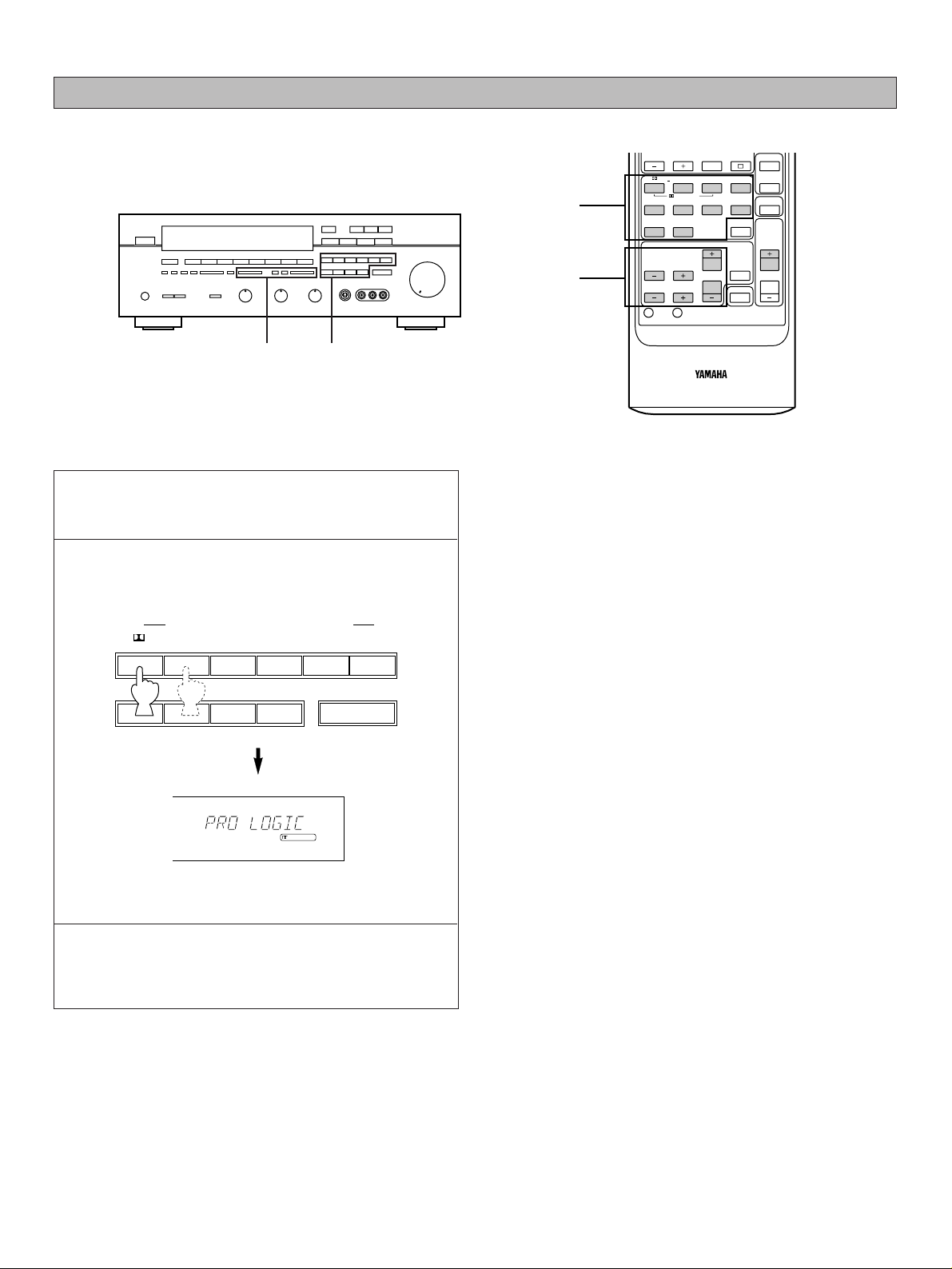
1 Follow steps 1 – 6 shown in “BASIC OPERATIONS” on
page 16.
2 Select the desired program that is suitable for the
source.
The selected program name is shown on the display.
3 If desired, adjust the delay time and the output level of
each speaker. (For details, refer to the corresponding
descriptions on page 26 and 27.)
Notes
●
If you prefer to cancel the DSP, press the EFFECT switch.
The sound will be the normal 2-channel stereo without
surround sound effect.
●
When STADIUM, ROCK CONCERT, JAZZ CLUB,
CHURCH or CONCERT HALL is selected, no sound is
heard from the center speaker.
●
When a monaural sound source is played with DOLBY
PRO LOGIC or DOLBY PRO LOGIC ENHANCED, no
sound is heard from the front speakers and the rear
speakers. Sound is heard only from the center speaker.
However, if the center channel mode is in PHANTOM, the
front speakers output the sound of the center channel.
●
When this unit’s Dolby Pro Logic Surround system is used,
if the main-source sound is considerably altered by
overadjustment of the BASS or TREBLE controls, the
relationship between the center and rear channels may
produce an unnatural effect.
25
To play a source with the digital sound field processor
2
3
CHAPTER/CH DISPLAY STOP VCR 1
VCR 2
TV
THEATER
70mm
MOVIE THEATER
ENHANCEDPRO LOGIC
V–AUXJAZZ CLUBROCKSTADIUMSPORTS
SURROUND
DSP
EFFECT
ON/OFF
MASTER
VOLUME
CENTER LEVEL
REAR LEVEL
DELAY
TIME
TEST
RESET CLEAR
1234
5678
MUTING
HALLCHURCH
910
2
3
PRO LOGIC
ROCK
CONCERT
JAZZ CLUB
DIGITAL SOUND FIELD PROCESSOR
ENHANCED
70mm
MOVIE THEATER
CHURCH
WIDE
TV
THEATER
CONCERT
HALL
PRO LOGIC
SPORTS
EFFECT
STADIUM
Page 26
26
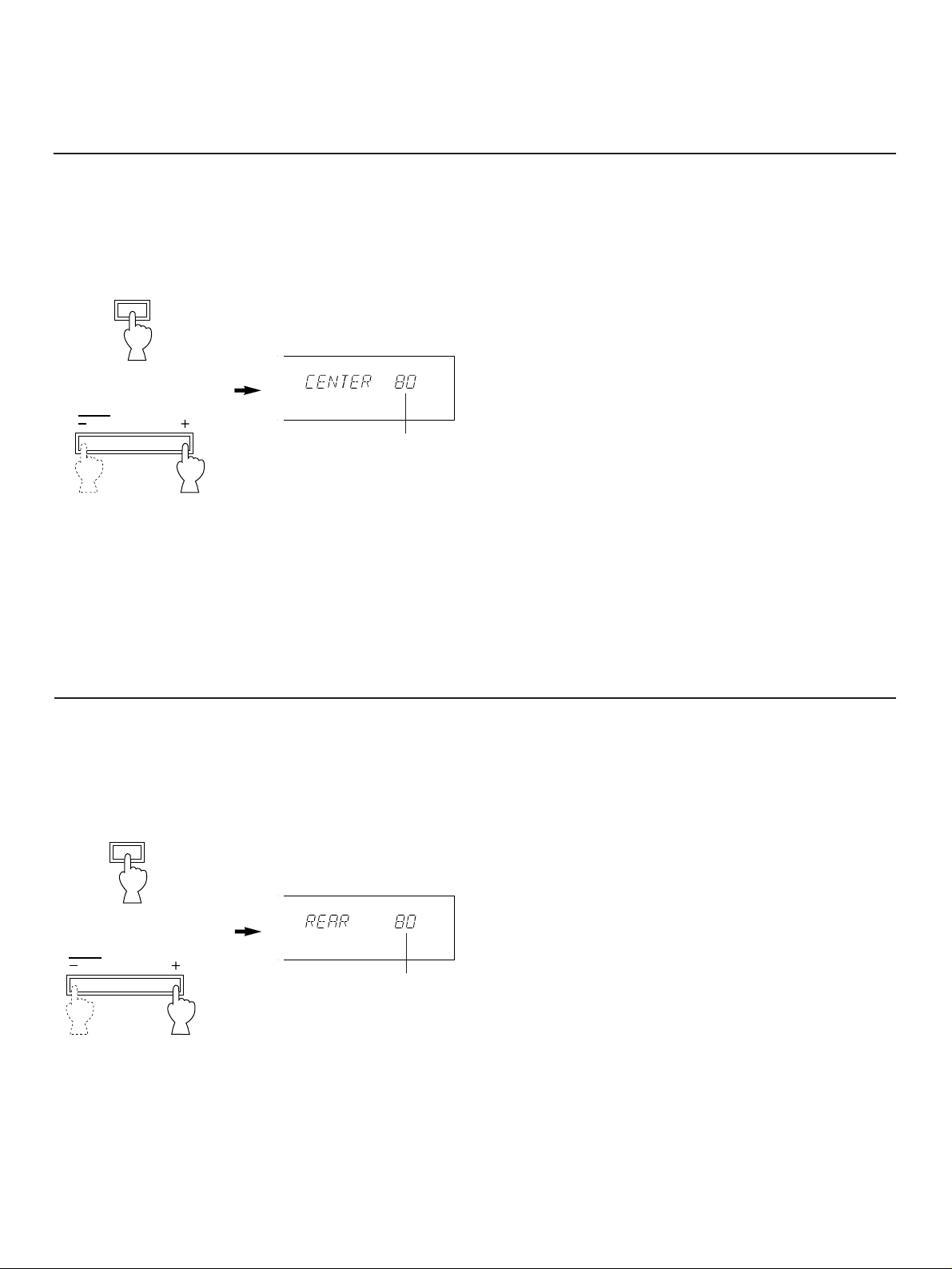
Adjustment of the REAR LEVEL
If desired, you can adjust the sound output level of the rear
speakers even if the output level is already set in “SPEAKER
BALANCE ADJUSTMENT” on page 15.
To operate on the front panel
1
2
Press “+” or “–” before “REAR”
disappears from the display.
To operate on the remote control transmitter
Simply press the REAR LEVEL “+” or “–” key.
By continuously pressing “+” or “–”, the level value changes
continuously. However, the value stops changing momentarily
at the preset point (80).
●
Once the output level is adjusted, the level value will be the
same in all the digital sound field programs.
●
If DOLBY PRO LOGIC or a digital sound field program is
not used, this adjustment cannot be made.
* The following adjustments can be done on the remote control transmitter as well as on the front panel.
If desired, you can adjust the sound output level of the center
speaker even if the output level is already set in “SPEAKER
BALANCE ADJUSTMENT” on page 15.
To operate on the front panel
1
2
Press “+” or “–” before “CENTER”
disappears from the display.
To operate on the remote control transmitter
Simply press the CENTER LEVEL “+” or “–” key.
By continuously pressing “+” or “–”, the level value changes
continuously. However, the value stops changing momentarily
at the preset point (80).
●
If the digital sound field program STADIUM, ROCK
CONCERT, JAZZ CLUB, CHURCH or CONCERT HALL is
selected, this adjustment cannot be made.
●
Once the output level is adjusted, the level value will be the
same in all the programs except mentioned above.
●
If a digital sound field program is not used, this adjustment
cannot be made.
Adjustment of the CENTER LEVEL
CENTER
Adjustable
LEVEL
REAR
Adjustable
LEVEL
Page 27
27
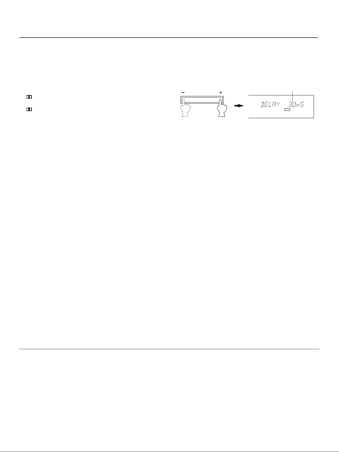
Adjustment of DELAY TIME
You can adjust the time difference between the beginning of
the source sound and the beginning of the effect sound with
the DELAY TIME control.
The DELAY TIME control is effective with all programs.
By applying more or less delay, sound effects, background
noise, and ambient noise coming at you from the rear speakers
can be enhanced or subdued for extra effect.
1. PRO LOGIC : from 15 to 30 milliseconds
(Preset value: 20 milliseconds)
2. PRO LOGIC : from 15 to 30 milliseconds
ENHANCED (Preset value: 20 milliseconds)
3. 70 mm MOVIE : from 1 to 50 milliseconds
THEATER (Preset value: 17 milliseconds)
4. TV THEATER : from 1 to 50 milliseconds
(Preset value: 28 milliseconds)
5. SPORTS : from 1 to 50 milliseconds
(Preset value: 20 milliseconds)
6. STADIUM : from 1 to 50 milliseconds
(Preset value: 45 milliseconds)
7. ROCK CONCERT : from 1 to 50 milliseconds
(Preset value: 22 milliseconds)
8. JAZZ CLUB : from 1 to 50 milliseconds
(Preset value: 26 milliseconds)
9. CHURCH : from 1 to 50 milliseconds
(Preset value: 40 milliseconds)
10. CONCERT HALL : from 1 to 50 milliseconds
(Preset value: 30 milliseconds)
By continuously pressing “+” or “–” on the DELAY TIME
control, the value changes continuously.
However, the value stops changing momentarily at the preset
point.
Note
Adding too much delay will cause an unnatural effect with
some sources. Experiment with the DELAY TIME control to
create the effect that you find most suitable.
DELAY TIME
DSP
Adjustable
Note
The values of the DELAY TIME, CENTER LEVEL and REAR
LEVEL you set the last time will remain memorized even when
the power of this unit is off.
However, if the power cord is kept disconnected for more than
one week, these values will be automatically changed back to
the original factory settings.
Page 28
28
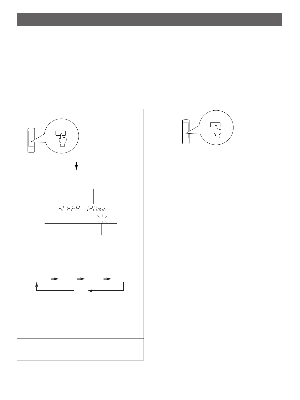
1
Whenever the SLEEP key is pressed, the SLEEP time will
change as follows.
After a while, the display returns to the indication before
the SLEEP timer is set, and the “SLEEP” indicator stops
flashing and lights up.
2 The unit will be turned off automatically at the selected
SLEEP time.
SETTING THE SLEEP TIMER
If you use the SLEEP timer of this unit, you can make this unit turn off automatically. When you are going to sleep while enjoying a
broadcast or other desired input source, this timer function is helpful.
Notes
●
The SLEEP timer can be controlled only with the remote control transmitter.
●
The components on which the SLEEP timer is effective are the sources connected to the SWITCHED AC OUTLET(S) on the rear
panel of this unit.
To set the SLEEP time
Press once or more to
select the desired
SLEEP time.
Indicates the SLEEP time.
Flashes on and off continuously.
To cancel the selected SLEEP time
Press once or more so that “SLEEP OFF” appears on the
display. (It will soon disappear and the “SLEEP” indicator will
go off from the display.)
Note
The SLEEP timer setting can also be canceled by turning off
the power with the POWER switch or disconnecting the power
plug of this unit from the AC outlet.
SLEEP
SLEEP
SLEEP
(Minutes)
120min 90min 60min 30min
OFF
(The SLEEP timer is off.)
Page 29
29
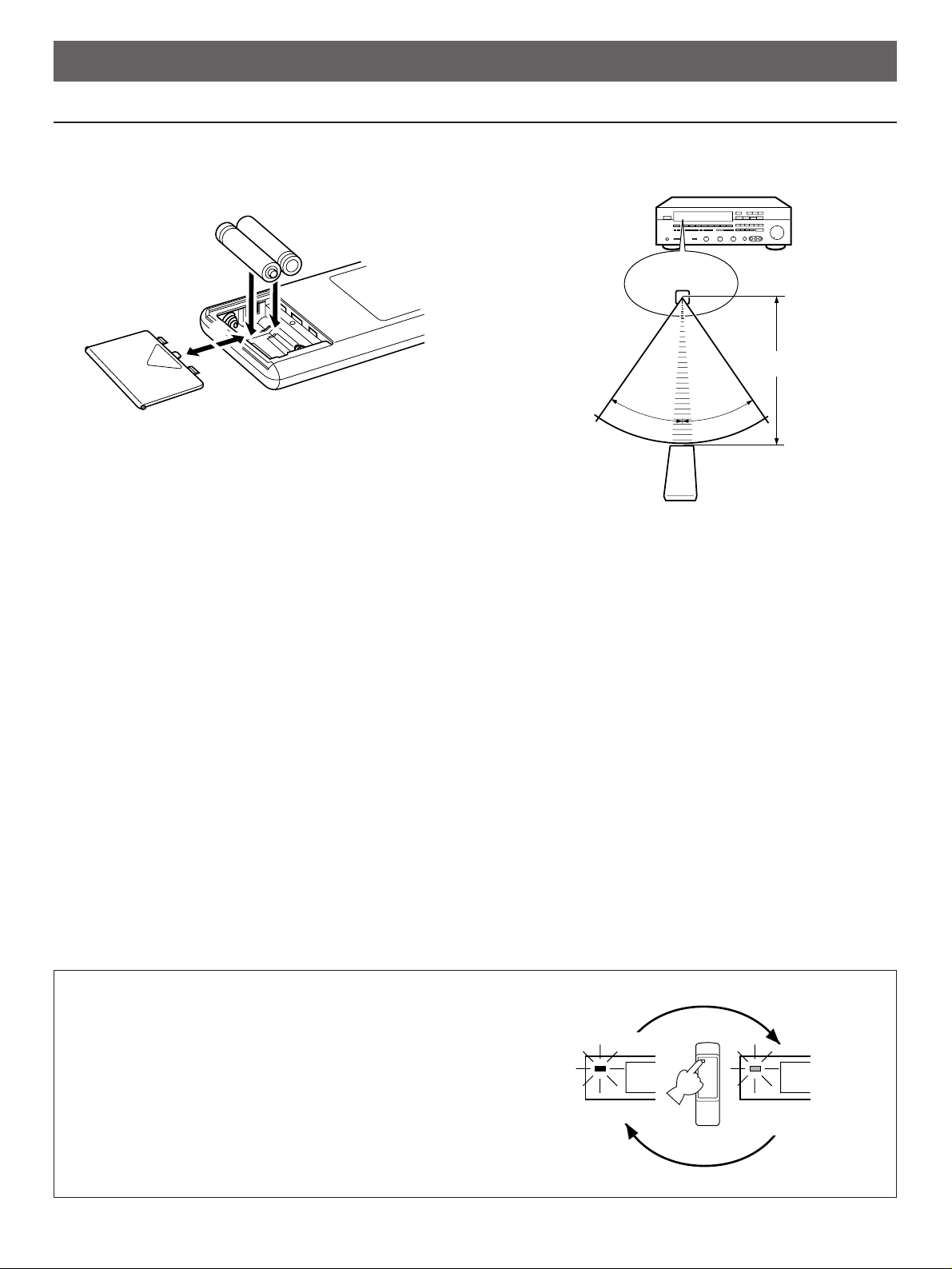
Battery installation
Battery replacement
If you find that the remote control transmitter must be used
closer to the main unit, the batteries are weak. Replace both
batteries with new ones.
Notes
●
Use only AA, R6, UM-3 batteries for replacement.
●
Be sure the polarities are correct. (See the illustration inside
the battery compartment.)
●
Remove the batteries if the remote control transmitter will
not be used for an extended period of time.
●
If batteries leak, dispose of them immediately. Avoid
touching the leaked material or letting it come in contact with
clothing, etc. Clean the battery compartment thoroughly
before installing new batteries.
Remote control transmitter operation range
Notes
●
There should be no large obstacles between the remote
control transmitter and the main unit.
●
If the remote control sensor is directly illuminated by strong
lighting (especially an inverter type of fluorescent lamp etc.),
it might cause the remote control transmitter not to work
correctly. In this case, reposition the main unit to avoid
direct lighting.
REMOTE CONTROL TRANSMITTER
NOTES ABOUT THE REMOTE CONTROL TRANSMITTER
30°
30°
Remote control
sensor
Within approximately
6m (19.7 feet)
1
2
3
STANDBY mode (Singapore model only)
While the power is on, pressing the POWER key on the remote
control transmitter switches the unit to the STANDBY mode. (In
this mode, the indicator is half illuminated.)
POWER on mode STANDBY mode
Page 30
30
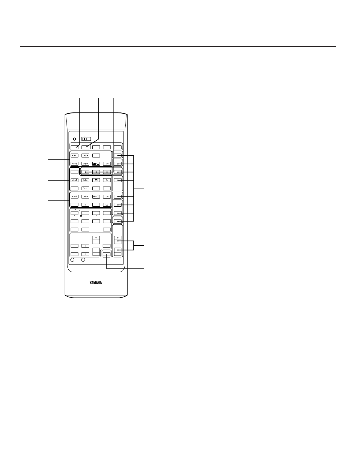
* When you operate this unit and/or other YAMAHA
components with this remote control transmitter, set the
YPC-USER-LEARN switch to the YPC (Yamaha Preset
Code) position.
For Other Component Control
Identify the remote control transmitter keys with your
component’s keys. If these keys are identical, their functions
will be the same. On each key function, refer to the
corresponding instruction on your component’s manual.
1 CD player keys
Controls compact disc player.
*
DISC SKIP is applicable only to compact disc changer.
2 Tape deck keys
Controls tape deck.
*
DIR A, B and DECK A/B are applicable only to double
cassette tape deck.
*
For a single cassette deck with automatic reverse
function, pressing DIR A will reverse the direction of
tape running.
3 LD player keys
Controls LD player.
*
Some models have a key which possesses both the
functions of PLAY and PAUSE.
For Control of This Unit
4 POWER
Turns the power on/off.
5 SLEEP
Refer to “SETTING THE SLEEP TIMER” on page 28.
6 Tuner keys
Controls tuner.
+: Selects higher preset station number.
–: Selects lower preset station number.
A/B/C/D/E Selects the page (A – E) of preset station
buttons.
7 Input selector keys
Selects input source.
8 MASTER VOLUME +/–
Turns the volume level up/down.
9 MUTE
When pressed, mutes the volume level. To resume original
volume level, press this again.
While muting, the indicator on the VOLUME control flashes
continuously.
* For the DSP control keys, refer to page 23.
The remote control transmitter provided with this unit is designed to control all the most commonly used functions of the unit. If the
CD player, tape deck, etc. connected to this unit are YAMAHA components, then this remote control transmitter will also control
various functions of each component.
KEY FUNCTIONS
POWER SLEEP TV VCR AUX
TRANSMIT
/LEARN
YPC
USER
LEARN
SKIP
DISC
SKIP
PHONO
CDPLAY
PAUSE/STOP
SEARCH
DECK A/B
PRESET
A/B/C/D/E
TUNER
TAPE MON
PLAYSTOPSEARCH
REC MUTE
REC/PAUSE
DIR A DIR B
LD/TVPLAY
PAUSE/STOP
SEARCH
CHAPTER/CH DISPLAY STOP VCR 1
VCR 2
TV
THEATER
70mm
MOVIE THEATER
ENHANCEDPRO LOGIC
V–AUXJAZZ CLUBROCKSTADIUMSPORTS
SURROUND
DSP
EFFECT
ON/OFF
MASTER
VOLUME
CENTER LEVEL
REAR LEVEL
DELAY
TIME
TEST
RESET CLEAR
1234
5678
MUTING
HALLCHURCH
910
1
2
3
456
7
8
9
Page 31
31
REMOTE CONTROL “LEARNING” FUNCTION
All of the keys on this remote control transmitter can be programmed to “learn” key-functions from other remote control transmitters
without losing the preset key functions. By using this feature, this unit can then be used in place of one or more other remote control
transmitters, thus making operation of your various audio and video components more convenient. Use the included user program
sheets to indicate a new function learned for each key.
Note
There may occasionally be instances in which, due to the signal-coding and modulation employed by the other remote control
transmitter, this unit will not be able to “learn” its signals.
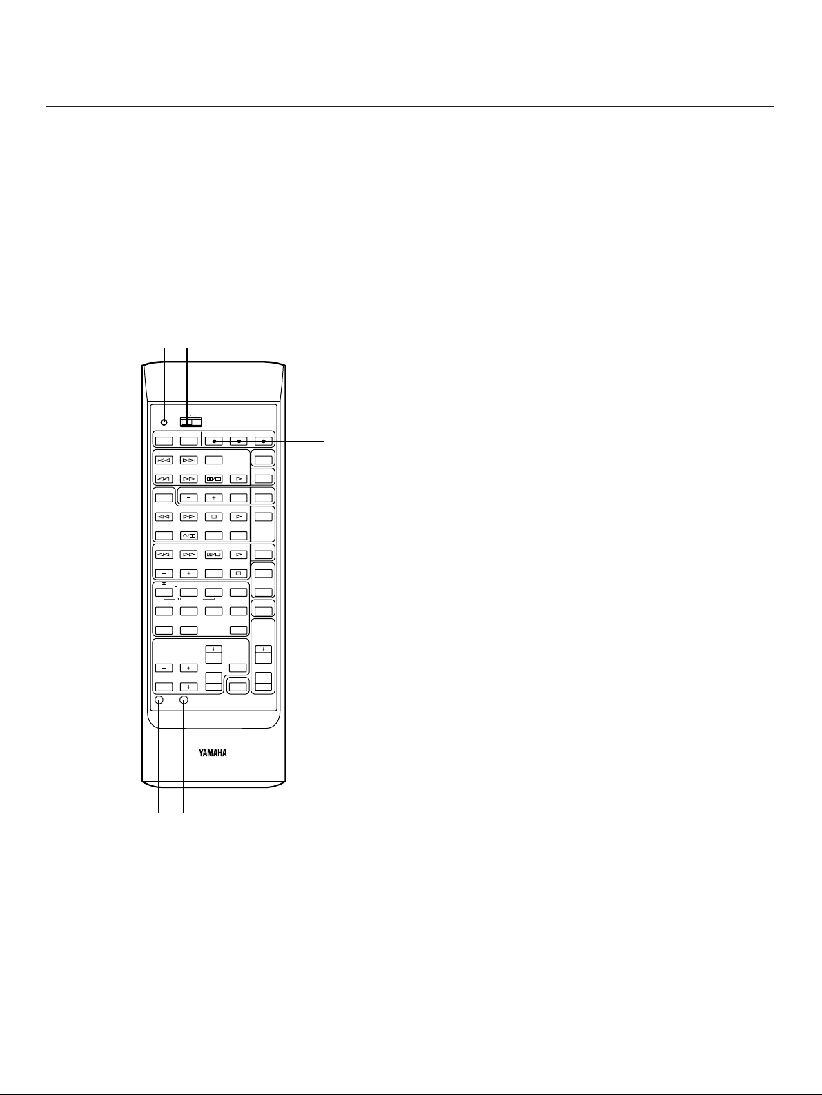
1 TRANSMIT/LEARN indicator
2 YPC-USER-LEARN switch
YPC: Set to this position when using preset key
functions (for controlling this unit and/or
YAMAHA components).
*
“YPC” is the abbreviation of YAMAHA Preset
Code.
USER: Set to this position when using “learned” key
functions.
LEARN: Set to this position when learning new key
functions from other remote control transmitters.
3 Blank keys
These keys have no preset functions and are used only for
learning other remote control transmitter’s functions.
4 RESET button
Press this button to “reset” the internal microcomputer
which controls remote control operations. Microcomputer
“reset” is necessary when the remote control freezes.
* Pressing the RESET button will not erase learned
functions.
5 CLEAR button
This button is used to clear one or all learned key functions.
(Refer to page 33.)
POWER SLEEP TV VCR AUX
TRANSMIT
/LEARN
YPC
USER
LEARN
SKIP
DISC
SKIP
PHONO
CDPLAY
PAUSE/STOP
SEARCH
DECK A/B
PRESET
A/B/C/D/E
TUNER
TAPE MON
PLAYSTOPSEARCH
REC MUTE
REC/PAUSE
DIR A DIR B
LD/TVPLAY
PAUSE/STOP
SEARCH
CHAPTER/CH DISPLAY STOP VCR 1
VCR 2
TV
THEATER
70mm
MOVIE THEATER
ENHANCEDPRO LOGIC
V–AUXJAZZ CLUBROCKSTADIUMSPORTS
SURROUND
DSP
EFFECT
ON/OFF
MASTER
VOLUME
CENTER LEVEL
REAR LEVEL
DELAY
TIME
TEST
RESET CLEAR
1234
5678
MUTING
HALLCHURCH
910
12
45
3
Page 32
32
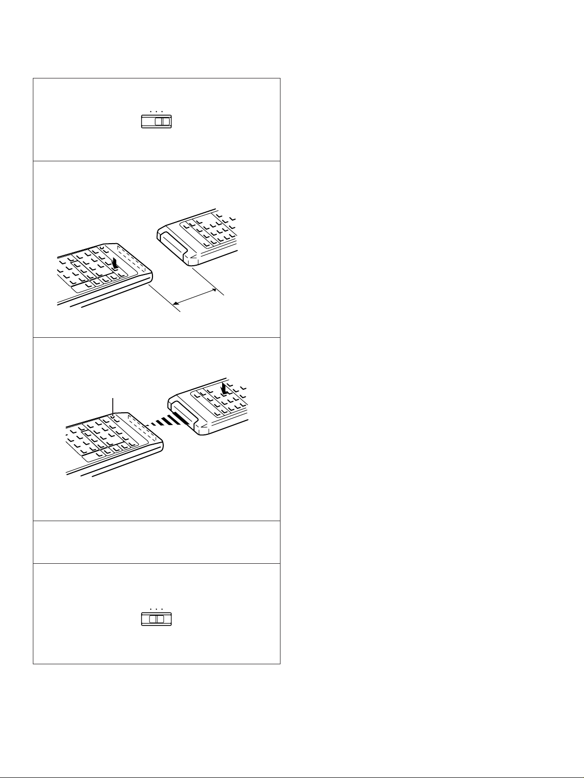
1
Set to the “LEARN” position.
2 Press a key on this unit where a new function will be
learned.
3 Press and hold the key (on the other remote control
transmitter) where the desired new function is.
* When the TRANSMIT/LEARN indicator stops lighting, the
learning is finished.
4 Repeat step 2 and 3 until all desired functions are
successfully learned.
5 Set to the “USER” position.
Try operating your components.
Notes
●
When you operate the desired component with this remote
control transmitter, TRANSMIT/LEARN indicator will flash
steadily.
●
The originally preset function of a key is still available in the
USER position if a new function has not been learned to the
key.
●
Successful learning to a key results in the erasure of
previously learned functions and their replacement by the
newly learned ones.
●
If there is no more room in the memory area for a function to
be learned, the TRANSMIT/LEARN indicator will flash on
and off. In this case, even if some keys are not occupied
with functions from other remote control transmitters, no
further learning is possible.
Memory back-up
All of the learned functions will be retained while you replace
the batteries. However, if no batteries are installed for a few
hours, the learned functions will be erased and will have to be
learned again.
To Learn a New Function
YPC
USER
LEARN
YPC
USER
LEARN
This unit
Other remote
control transmitter
About 5–10 cm
(2–4 in.)
Lights up.
Page 33
33
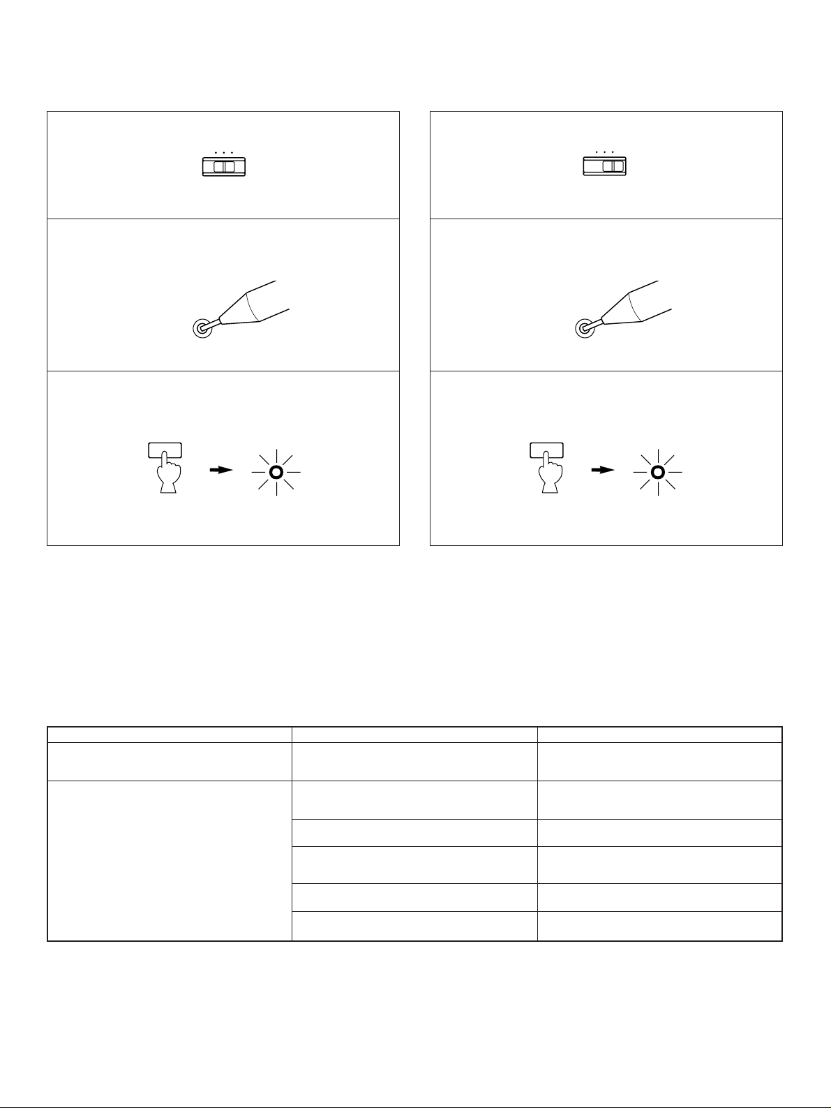
1
Set to the “USER” position.
2 Press and hold the CLEAR button using the point of a
mechanical pencil, etc.
3 Press and hold the key where the learned function to be
deleted is until the indicator flashes 3 times.
To clear two or more functions, repeat step 2 and 3.
Note
If a key is not pressed soon after the CLEAR button is pressed,
this unit will automatically return to the status that was in effect
before the CLEAR button was pressed.
To Clear a Learned Function To Clear All Learned Functions
1
Set to the “LEARN” position.
2 Press and hold the CLEAR button using the point of a
mechanical pencil, etc.
3 Press and hold any key until the indicator flashes 7
times.
CLEAR
TRANSMIT
/LEARN
CLEAR
TRANSMIT
/LEARN
SYMPTOM
The remote control transmitter does not
work.
Learning cannot be made successfully.
(The TRANSMIT/LEARN indicator does not
light up or flash.)
CAUSE
The batteries of this remote control
transmitter are weak.
The internal microcomputer “freezes”.
The batteries of this remote control
transmitter and/or the other remote control
transmitter are weak.
The distance between the two remote control
transmitters is too long or too short.
The signal coding or modulation of the other
remote control transmitter is not compatible
with this remote control transmitter.
Memory capacity is full.
The internal microcomputer “freezes”.
REMEDY
Replace the batteries with new ones and
press the RESET button on the remote
control transmitter.
Replacce the batteries (and press the RESET
button for this remote control transmitter).
Place the remote control transmitters with the
proper distance.
Learning is not possible.
Further learning is not possible without
deleting unnecessary commands.
Press the RESET button on the remote
control transmitter.
Trouble shooting guide
YPC
USER
LEARN
YPC
USER
LEARN
Page 34
34
AmplifierFMAMOthers
Remote control
transmitter
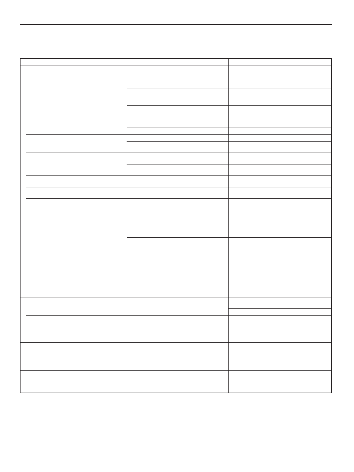
TROUBLESHOOTING
If the unit fails to operate normally, check the following points to determine whether the fault can be corrected by the simple
measures suggested. If it cannot be corrected, or if the fault is not listed in the SYMPTOM column, disconnect the power cord and
contact your authorized YAMAHA dealer or service center for help.
SYMPTOM
The unit fails to turn on when the POWER
switch is pressed.
No sound or no picture.
The sound suddenly goes off.
Only one side speaker outputs the sound.
Sound “hums”.
The volume level is low while playing a record.
The volume level cannot be increased, or
sound is distorted.
No sound from the rear speakers.
No sound from the center speaker.
FM stereo reception is noisy.
There is distortion and clear reception cannot
be obtained even with a good FM antenna.
A desired station cannot be tuned in with Auto
tuning.
A desired station cannot be tuned in with Auto
tuning.
There are continuous crackling and hissing
noises.
There are buzzing and whining noises
(especially in the evening).
The remote control transmitter does not work.
The sound is degraded when monitoring is
performed by using the headphones connected
to the compact disc player or cassette deck
which are connected with this unit.
CAUSE
Power cord is not plugged in or is not completely
inserted.
Incorrect output cord connections.
The MUTING key is ON.
Appropriate input selector is not pressed.
The protection circuit has been activated because
of short circuit etc.
The SLEEP timer functioned.
Incorrect setting of the BALANCE control.
Incorrect cord connections.
Incorrect cord connections.
No connection from the turntable to the GND
terminal.
The record is being played on a turntable with an
MC cartridge.
The power to the component connected to the REC
OUT terminals of this unit is off.
The sound output level to the rear speakers is set
to 0.
The monaural sound source is played in DOLBY
PRO LOGIC or DOLBY PRO LOGIC ENHANCED
mode.
The sound output level to the center speaker is set
to 0.
The center channel mode is in PHANTOM mode.
Incorrect sound field program selection.
No sound field program is selected.
Because of the characteristics of FM stereo
broadcasts, this is limited to cases where the
transmitter is too far away or the antenna input is poor.
There is multipath interference.
The station is too weak.
Weak signal or loose antenna connections.
Noises will result from lightning, fluorescent lamps,
motors, thermostats and other electrical equipment.
A television set is being used nearby.
Direct sunlight or lighting (of an inverter type of
flourescent lamp etc.) is striking the remote control
sensor of the main unit.
The batteries of this remote control transmitter are
too weak.
The power to this unit is off.
REMEDY
Firmly plug in the power cord.
Connect the cords properly. If the problem persists,
the cords may be defective.
First, turn the volume control to full left. Then, turn
the MUTING key OFF with the remote control
transmitter and adjust the volume.
Press the appropriate input selector corresponding
to the input source.
Turning the unit off and then on will reset the
protection circuit.
Cancel the SLEEP timer function.
Adjust it to the appropriate position.
Connect the cords properly. If the problem persists,
the cords may be defective.
Firmly connect the audio plugs. If the problem
persists, the cords may be defective.
Make the GND connection between the turntable
and this unit.
The player should be connected to the unit through
the MC head amplifier.
Turn the power to the component on.
Turn up the sound output level with the REAR
LEVEL control.
Select another program suitable for the monaural
sound source.
Turn up the sound output level with the CENTER
LEVEL control.
Select NORMAL or WIDE.
Select the appropriate program.
Check the antenna connections.
Try using a multiple element FM antenna.
Adjust antenna placement to eliminate multipath
interference.
Use Manual tuning mode.
Use a high quality directional FM antenna.
Tighten the AM loop antenna connections and
rotate it for best reception.
Use Manual tuning mode.
Use an outdoor antenna and a ground wire. This
will help somewhat but it is difficult to eliminate all
noise.
Relocate this unit away from the TV.
Change the position of the main unit.
Replace the batteries with new ones.
Turn the power to this unit on.
Page 35

35
SPECIFICATIONS
AUDIO SECTION
Minimum RMS Output Power per Channel
Front L, R
8 ohms, 20 Hz to 20 kHz, 0.04% THD
[U.S.A. and Canada models]
...................................................80W+80W
[Australia, Singapore and General models]
...................................................75W+75W
6 ohms, 20 Hz to 20 kHz, 0.04% THD
[U.S.A. model only]....................85W+85W
Center
8 ohms, 1 kHz, 0.07% THD
[U.S.A. and Canada models]
............................................................80W
[Australia, Singapore and General models]
............................................................75W
Rear L, R
8 ohms, 1 kHz, 0.3% THD............25W+25W
Maximum Output Power [General model only]
8 ohms, 1 kHz, 10% THD (FRONT L/R)
.................................................115W+115W
Dynamic Power per Channel
(by IHF Dynamic Headroom measuring
method)
8/6/4/2 ohms.................115/140/170/210W
Dynamic Headroom
[U.S.A. and Canada models only]
8 ohms............................................1.58 dB
Power Band Width
8 ohms, 40W, 0.08% THD
..........................................10 Hz to 50 kHz
Damping Factor (SPEAKERS A)
8 ohms, 20 Hz to 20 kHz .............80 or more
Input Sensitivity/Impedance
PHONO MM.....................2.5 mV/47 k-ohms
CD/TAPE/LD·TV/VCR
......150 mV/47 k-ohms
Maximum Input Signal
PHONO MM (1 kHz, 0.04% THD)
............................................110 mV or more
CD/TAPE/LD·TV/VCR (
1 kHz, 0.5% THD,
EFFECT ON)
............................2.2V or more
Output Level/Impedance
REC OUT.......................150 mV/1.0 k-ohms
PRE OUT
............................2.2V/1.2 k-ohms
LPF (EFFECT OFF)
.............3.5V/1.5 k-ohms
Headphone Jack Rated Output/Impedance
Output Level (8 ohms, 1 kHz, 150 mV)
............................................................0.5V
Impedance.....................................390 ohms
Frequency Response (20 Hz to 20 kHz)
CD/TAPE/LD·TV/VCR (FRONT L/R)
........................................................0±0.5 dB
RIAA Equalization Deviation
PHONO MM....................................0±0.5 dB
Total Harmonic Distortion
PHONO MM to REC OUT
20 Hz to 20 kHz, 1V..............0.02% or less
CD/TAPE/LD·TV/VCR
to SP OUT
FRONT L/R (EFFECT OFF)
20 Hz to 20 kHz, 40W/8 ohms
...........................................0.02% or less
REAR L/R
1 kHz, 10W/8 ohms..............0.3% or less
Signal-to-Noise Ratio (IHF-A Network)
PHONO MM to REC OUT (5 mV Input
Shorted)..................................86 dB or more
CD/TAPE/LD·TV/VCR
to SP OUT
(150 mV Input Shorted, EFFECT OFF)
............................................98 dB or more
Residual Noise (IHF-A Network)
FRONT L/R............................140 µV or less
Channel Separation
(Vol. –30 dB, EFFECT OFF)
PHONO MM
(Input Shorted 1 kHz/10 kHz)
.....................60 dB or more/50 dB or more
CD/TAPE/LD·TV/VCR
(Input 5.1 k-ohms Shorted 1 kHz/10 kHz)
.....................60 dB or more/45 dB or more
Tone Control Characteristics
BASS: Boost/cut................±10 dB (50 Hz)
Turnover Frequency.........(350 Hz)
TREBLE: Boost/cut...........±10 dB (20 kHz)
Turnover Frequency.....(3.5 kHz)
Filter Characteristics
LPF (fc=200 Hz)...............................6 dB/oct
Gain Tracking Error (0 to –60 dB)
...................................................3 dB or less
Audio Muting.............................................–
∞
VIDEO SECTION
Video Signal Level..................1 Vp-p/75 ohms
S-Video Signal Level
Y ..........................................1 Vp-p/75 ohms
C ...................................0.286 Vp-p/75 ohms
Maximum Input Level............1.5 Vp-p or more
Signal-to-Noise Ratio................50 dB or more
Monitor Out Frequency Response
..................................5 Hz to 10 MHz, –3 dB
FM SECTION
Tuning Range
[U.S.A. and Canada models]
.........................................87.5 to 107.9 MHz
[Australia, Singapore and General models]
.........................................87.5 to 108.0 MHz
50 dB Quieting Sensitivity (IHF, 75 ohms)
Mono................................1.55 µV (15.1 dBf)
Stereo .................................21 µV (37.7 dBf)
Usable Sensitivity (75 ohms)
(30 dB S/N Quieting, 1 kHz, 100% mod.)
..........................................0.8 µV (9.3 dBf)
Image Response Ratio...........................45 dB
IF Response Ratio..................................80 dB
Spurious Response Ratio.......................70 dB
AM Suppression Ratio............................55 dB
Capture Ratio........................................1.5 dB
Alternate Channel Selectivity ................85 dB
Signal-to-Noise Ratio (IHF)
Mono/Stereo .............................80 dB/75 dB
Harmonic Distortion (1 kHz)
Mono/Stereo ...................................0.1/0.2%
Stereo Separation (1 kHz)......................50 dB
Frequency Response
20 Hz to 15 kHz.............................0 ±1.5 dB
AM SECTION
Tuning Range
[U.S.A., Canada and General models]
...........................................530 to 1,710 kHz
[Australia and Singapore models]
...........................................531 to 1,611 kHz
Usable Sensitivity.............................100 µV/m
Selectivity...............................................32 dB
Signal-to-Noise Ratio .............................50 dB
Image Response Ratio...........................40 dB
Spurious Response Ratio.......................50 dB
Harmonic Distortion (1 kHz) ....................0.3%
AUDIO SECTION
Output Level/Impedance
FM (100% mod., 1 kHz)
.....................................500 mV/2.2 k-ohms
AM (30% mod., 1 kHz)
.....................................150 mV/2.2 k-ohms
GENERAL
Power Supply
[U.S.A. and Canada models]
............................................AC 120V, 60 Hz
[Australia model]..................AC 240V, 50 Hz
[Singapore model] ...............AC 230V, 50 Hz
[General model]
..................AC 110/120/220/240V, 50/60 Hz
Power Consumption
[U.S.A. and Canada models]
................................................310W/380 VA
[Australia, Singapore and General models]
.............................................................320W
Maximum Power Consumption
[General model only]............................620W
AC Outlets
2 SWITCHED OUTLETS
[U.S.A., Canada, Singapore and General
models].............................120W max. total
1 SWITCHED OUTLET
[Australia model]...............120W max. total
Dimensions (W x H x D)
........................................435 x 146 x 386 mm
(17-1/8” x 5-3/4” x 15-3/16”)
Weight..............................10 kg (22 lbs. 0 oz.)
Accessories..........................AM loop antenna
Indoor FM antenna
Remote control transmitter
Batteries
User Program Sheets
Specifications are subject to change without
notice.
Page 36
YAMAHA ELECTRONICS CORPORATION, USA 6660 ORANGETHORPE AVE., BUENA PARK, CALIF. 90620, U.S.A.
YAMAHA CANADA MUSIC LTD. 135 MILNER AVE., SCARBOROUGH, ONTARIO M1S 3R1, CANADA
YAMAHA ELECTRONIK EUROPA G.m.b.H. SIEMENSSTR. 22-34, D-25462 RELLINGEN BEI HAMBURG, F.R. OF GERMANY
YAMAHA ELECTRONIQUE FRANCE S.A. RUE AMBROISE CROIZAT BP70 CROISSY-BEAUBOURG 77312 MARNE-LA-VALLEE CEDEX02, FRANCE
YAMAHA ELECTRONICS (UK) LTD. YAMAHA HOUSE, 200 RICKMANSWORTH ROAD WATFORD, HERTS WD1 7JS, ENGLAND
YAMAHA SCANDINAVIA A.B. J A WETTERGRENS GATA 1, BOX 30053, 400 43 VÄSTRA FRÖLUNDA, SWEDEN
YAMAHA MUSIC AUSTRALIA PTY, LTD. 17-33 MARKET ST., SOUTH MELBOURNE, 3205 VIC., AUSTRALIA
VS 94270
 Loading...