

Page 1
Quick Reference Guide
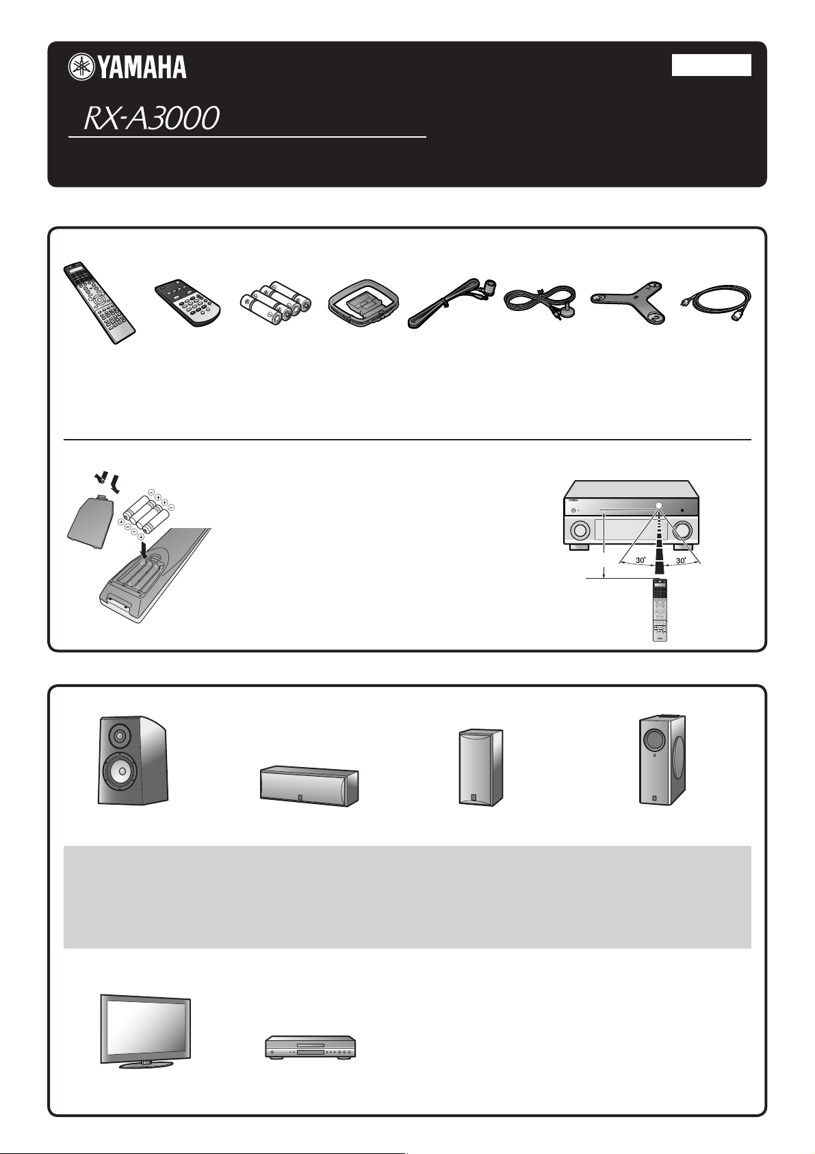
Accessories
■
The following accessories are supplied with this product.
English
for U.S.A.
Remote control Batteries (4)
* The gure of the supplied power cable may differ depending upon regions.
Simple remote
control
(AAA, LR03, UM-4)
AM loop antenna Indoor FM antenna
Preparing the remote control
Take off the battery compartment cover.
1
3
1
Insert the four supplied AAA batteries
2
into the battery case, following the
polarity markings.
2
Snap the battery compartment cover
3
back into place.
Items necessary for connection
■
Speakers
YPAO microphone Microphone base
Be sure to aim the remote control directly at the remote
control sensor on this unit during operation.
within 20 feet (6 m)
Power cable
✽
E.g. E.g.
Front speaker
• Use speakers with an impedance of at least 6 Ω. 4 Ω speakers can also be used as the front speakers. For more information on speaker
impedance, refer to page 3.
• If you are using a CRT monitor, we recommend that you use magnetically shielded speakers.
• Prepare at least two front speakers. The priority of the other speakers is as follows:
1 Two surround speakers
2 One center speaker
3 One (or two) surround back speaker (s)/presence speakers
Center speaker Surround speaker, surround back
External components
TV
Playback device such as
BD (Blu-ray Disc)/DVD players
E.g. E.g.
Active subwoofer
speaker, and presence speaker
Cable
• Cables for connecting external components
(may differ depending on the components you are connecting)
• Speaker cables
(a quantity to match the number of speakers you are connecting)
• Audio pin cable
(for subwoofer)
- 1 -
Page 2
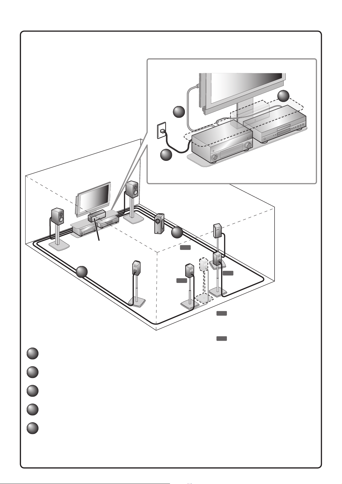
Connect and install as follows the rst time you use this unit.
See the following explanations for the connections for each number.
2
4
TV
3
BD/DVD player
(recorder)
This unit
Front
speaker L
Center speaker
1
1
Connect the speakers
Surround
speaker L
Front
speaker R
Subwoofer
Surround back
speaker L
1
6.1
Surround back
speaker
7.1
Surround
speaker R
7.1
Surround back
speaker R
7.1
Connect when using with 7.1-channel speaker
layout. Place the surround back speakers
(L/R) 12 in (30 cm) or more away from each
other.
6.1
Connect when using with 6.1-channel speaker
layout. Place the surround back speaker
behind the listening position.
2
Connect a TV
3
Connect playback devices such as BD/DVD players and recorders
4
Connect the power cable
5
Set up the speaker parameters automatically (YPAO)
- 2 -
Page 3
///
/
/
/
/
FRO
N
T
(
S
IN
GL
E
)
RE OUT
CE
NTER
CE
NTER
S
U
R
.
BA
C
KSU
R
R
U
ND
1
2
FR
O
NT
F
R
O
N
T
1
AV 1 AV 2 AV 3 AV 4
PBPRYPBP
FRONT
E3/
CE
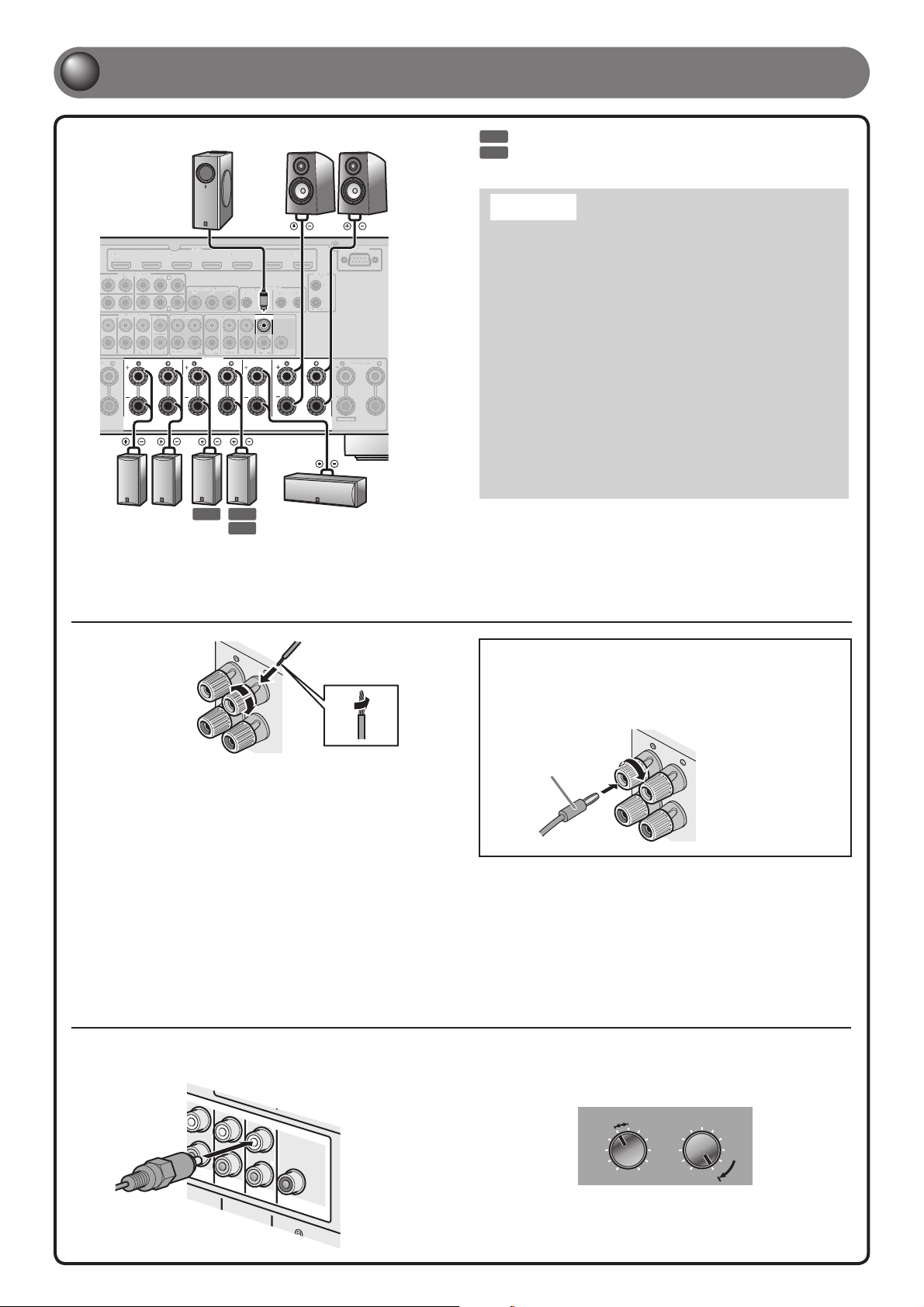
Connect the speakers
Front speaker
R L
REMOTE
12
OUT IN OUT
(FRONT)(SINGLE)
1
2
(REAR)
CENTER
SUBWOOFER
CENTER
FRONT
Center speaker
TRIGGER
OUT
1
2
+12V 0.1A MAX.
EXTRA SP1
RS-232C
ZONE2/ZONE3/
F.PRESENCE
(1 BD/DVD)
COMPONENT VIDEO
AV 3
AV 4
MULTI CH INPUT
SURROUND
SUR. BACK
SURROUND SURROUND BACK/
R L
Surround
speaker
CENTER
SUBWOOFER
C
D
ZONE 2
Subwoofer
HDMI
R
MONITOR OUT/ZONE OUT
YPBP
ZONE OUT PRE OUT
ZONE 3/
FRONT/
SURROUND
R. PRESENCE
F. PRESENCE
SPEAKERS
BI-AMP
SINGLE
7.1 7.1
R L
Surround back
speaker
AV 5 AV 6 AV 7
R
IN
SUR. BACK
6.1
7.1
Connect when using with 7.1-channel speaker layout.
6.1
Connect when using with 6.1-channel speaker layout.
Caution:
• Remove the power cable of this unit from the power outlet before
connecting the speakers.
• Generally speaker cables consist of two parallel insulated
cables. One of these cables is a different color, or has a line
running along it, to indicate different polarity. Insert the different
colored (or lined) cable into the “+” (positive, red) terminal
on this unit and the speakers, and the other cable into the “-”
(minus, black) terminal.
• Be careful that the core of the speaker cable does not touch
anything or come into contact with the metal areas of this unit.
This may damage this unit or the speakers. If the speaker cables
short circuit, “CHECK SP WIRES!” will appear on the front panel
display when this unit is switched on.
• This unit is con gured for 8 Ω speakers at the factory setting.
When connecting 6 Ω speakers, con gure the speaker
impedance setting of this unit to 6 Ω. When this unit is
con gured for 6 Ω speakers, 4 Ω speakers can also be used as
the front speakers. For more information on setting the speaker
impedance, refer to “Changing speaker impedance” in the
Owner’s Manual.
• When connecting the presence speakers, refer to “Presence speaker
connection” in the Owner’s Manual.
• This unit can connect speakers that support Bi-amp connection for front
speakers. Refer to “Bi-amp connection” in the Owner’s Manual.
Connecting speakers
3
+
2
-
1
4
Remove approximately 10 mm (0.4 in) of
1
insulation from the ends of the speaker cables,
and twist the bare wires of the cables together
rmly so that they will not cause short circuits.
Loosen the speaker terminals.
2
Insert the bare wire of the speaker cable into the
3
gap on the side of the terminal.
Tighten the terminal.
4
Connecting the subwoofer
Connect the subwoofer input jack to the SUBWOOFER
1
1 jack on this unit with an audio pin cable.
(
F
R
ONT
)
Connecting the banana plug
Tighten the knob, and then insert the banana plug
into the end of the terminal.
+
Banana plug
Set the subwoofer volume as follows.
2
Volume: Set to approximately half volume (or slightly less than half).
Crossover frequency (if available): Set to maximum.
CROSSOVER/
VOLUME
HIGH CUT
S
UBWO
(
R
EA
R
)
OF
E
R
- 3 -
MIN MAX
Subwoofer examples
MIN MAX
Page 4
E
///
/
/
/
/
ZONE2/ZONE3/
ANTENNA
R.PRESENCE
AV 1
HDMI OUT
A
EXTRA SP2
12
NETWORK
AV 1
AV 2
OPTICAL OPTICAL
OPTICAL
AUDIO 1
(2 TV)
(3 CD)
AUDIO 2 AUDIO 3 AUDIO 4
FRONT
SURROUND
SU
MULTI CH IN
COMPONENT
COAXIAL
MON.OUT/ZONE OUT
AV OUT
AV OUT/
ZONE 4
Ԛԛ Ԝԝ
YPBP
R
A
B
(1 BD/DVD)
HD Radio
GND
AMM
(4 RADIO)
ARC
SELECTABLE
ARC
/
/
/
/
/
2
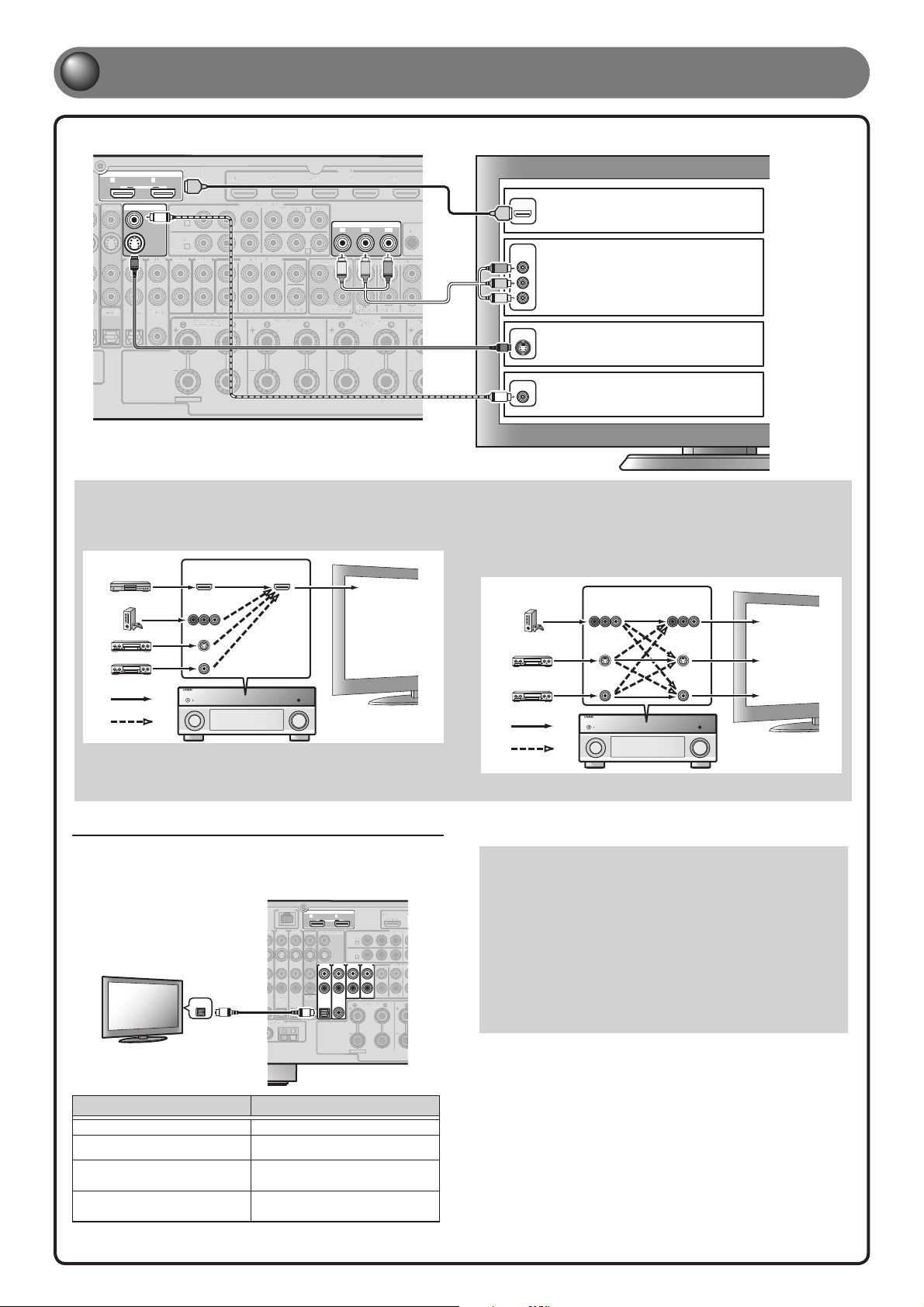
Connect a TV
If your TV has multiple inputs, connect with the following priority (A to D).
HDMI OUT
12
ARC ARC
SELECTABLE
AV OUT
MON.OUT/ZONE OUT
V
AUDIO 1
AUDIO 2 AUDIO 3 AUDIO 4
(2 TV)
(3 CD)
S
AV OUT/
AL
OPTICAL
COAXIAL
Ԝԝ
ZONE 4
EXTRA SP2
* For details on selecting the active HDMI OUT jack, refer to
“Selecting the active HDMI OUT jack” in the Owner’s Manual.
When connecting to an HDMI compatible TV
Video signal such as component video, S-video and video received by
this unit is converted to HDMI and output to the TV. Just select HDMI
input on the TV to view video from any external source connected to
this unit.
AV 1
AV 2 AV 3 AV 4
HDMI
AV 1
A
AV 2
B
(1 BD/DVD)
COMPONENT VIDEO
YPBPRYPBP
MULTI CH INPUT
FRONT
SURROUND
ZONE2/ZONE3/
R.PRESENCE
Input Output
HDMI
COMPONENT
VIDEO
O
E
D
I
V
S
VIDEO
SUR. BACK
AV 3
AV 4
CENTER
SUBWOOFER
SURROUND SURROUND BACK/
HDMI
Through
Converted
For more information on video signal conversion, refer to “Connecting a TV monitor” in the Owner’s Manual.
HDMI
R
C
MONITOR OUT/ZONE OUT
YPBP
D
ZONE OUT PRE OUT
P
Y
ZONE 3/
R. PRESENCE
FRONT/
F. PRESENCE
SPEAKERS
BI-AMP
ZONE 2
HDMI input
AV 5
A When the HDMI input is
HDMI
HDMI
R
IN
COMPONENT
(SINGLE)
P
R
B
SURROUND
SUR. BACK
C
SINGLE
TV
VIDEO
P
R
P
B
Y
S VIDEO
S
VIDEO
V
When connecting to a non-HDMI compatible TV
Connect to the TV using the same type of connection that you used to
connect to the playback device.
If the playback device and TV are equipped with different types of
analog video jacks, this unit will convert the video signals to another
type of video signal, according to the type of video input jacks used
on the TV.
available.*
B When the component
video input is available.
C When the S-video input is
available.
D When only the video input
is available.
Input Output
COMPONENT
VIDEO
O
DE
VI
S
Through
Converted
COMPONENT
VIDEO
O
DE
VI
S
VIDEOVIDEO
TV
Component
video input
S-video input
Video input
Listening to TV audio
To play back TV audio on this unit, connect the TV audio output to this unit.
Connect the following input jacks, matching the audio output jacks on your TV.
When viewing your TV, select the appropriate input source on this unit.
OPTICAL
O
Audio
output
Audio output from TV Input jack on this unit
Optical digital output AUDIO1
Coaxial digital output AUDIO2
Analog output
HDMI Audio Return Channel
(Described in the right column)
AUDIO1, AUDIO2, AUDIO3, or
AUDIO4
HDMI OUT 1 or HDMI OUT 2
✽ Connecting to AUDIO1 allows you to playback TV audio just by pressing
the SCENE2 key.
O
When using a TV that supports the Audio Return Channel
function and HDMI Control function
When using an HDMI compatible TV that supports
Audio Return Channel functions and / or HDMI Control functions
(e.g., Panasonic VIERA Link), you can enjoy the TV sound on this
unit.
The audio / video output from the unit to the TV and audio output
from the TV to the unit are possible using a single HDMI cable.
The input source is switched automatically to match operations
carried out on the TV, and that makes TV sound control easier to
use.
For the connections and settings, refer to “Using the HDMI Control
function” in the Owner’s Manual.
- 4 -
Page 5
O
R
/
/
/
/
/
O
/
/
3
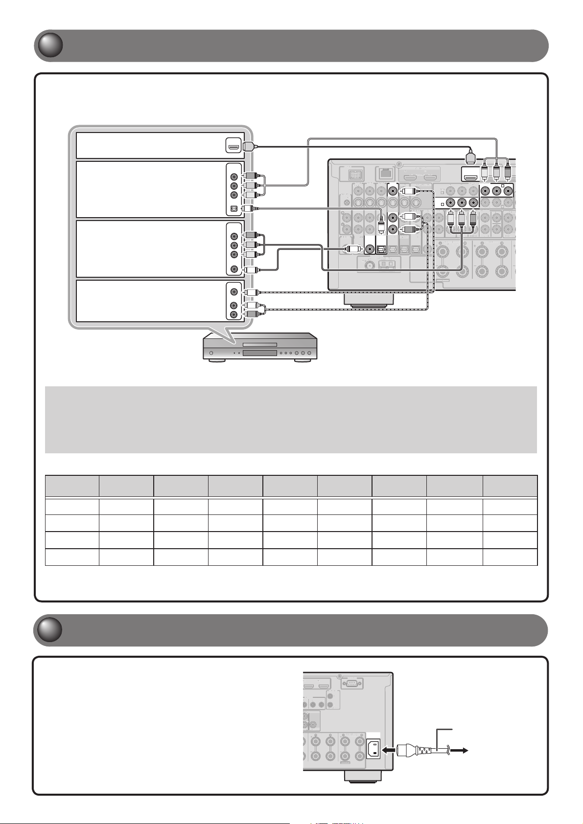
Connect playback devices such as BD/DVD players and recorders
If your playback device has multiple audio/video outputs, connect with the following priority
(A to D) to enjoy a higher quality sounds and images.
A When the HDMI output is
available.
B When the component video
output is available (with
optical digital audio output).
C When the component video
output is available (with
coaxial digital audio output).
D When only the video input
is available (with the analog
audio output).
HDMI
COMPONENT
VIDEO
OPTICAL
COMPONENT
VIDEO
COAXIAL
VIDEO
AUDIO
HDMI
P
R
P
B
Y
O
P
R
P
B
Y
C
V
L
R
DOCK NETWORK
AV 1
AV 2 AV 3 AV 4
(1 BD/DVD)
PHONO
GND
SIRIUS
O
COAXIAL COAXIAL
OPTICAL OPTICAL
ԘԙԚԛ Ԝԝ
C
ANTENNA
(4 RADIO)
HD Radio
GND
75
12
AV OUT
AV OUT/
ZONE 4
AMFM
HDMI OUT
ARC ARC
SELECTABLE
MON.OUT/ZONE OUT
V
AUDIO 1
(2 TV)
L
R
OPTICAL
AUDIO 2 AUDIO 3 AUDIO 4
(3 CD)
COAXIAL
EXTRA SP2
HDMI
AV 1
(1 BD/DVD)
COMPONENT VIDEO
YPBPRYPBP
AV 1
A
AV 2
B
MULTI CH INPUT
PBP
R
Y
FRONT
SURROUND
ZONE2/ZONE3/
R.PRESENCE
SUR. BACK
AV 2 AV 3
YP
B
AV 3
AV 4
CENTER
SUBWOOFER
SURROUND
C
D
ZONE 2
R
P
R
ZONE
✽ Refer to “Connecting BD/DVD players and other devices” in Owner's Manual for details on connection other than above illustration.
• When playing back a device, select the corresponding input source to which the jack is connected.
• If necessary, you can connect components that cannot be connected using the above methods, such as devices that output video from
component video output jacks and audio from analog output jacks. Refer to “Connecting external components” in the Owner’s Manual for
details.
• At the default settings, input sources and sound programs are preset on the SCENE keys. When a playback device is connected to AV1,
pressing the SCENE1 key selects the AV1 input. When a playback device is connected to AUDIO2, pressing the SCENE3 selects the AUDIO2
input. The input source and sound program preset on the SCENE key can be changed.
Default scene settings
SCENE Input Audio Select HDMI Output
Sound
Program
1 (BD/DVD) AV1 Auto OUT1+2 Drama Auto
2 (TV) AUDIO1 Auto OUT1+2 STRAIGHT Auto
3 (CD) AUDIO2 Auto OUT1+2 STRAIGHT Auto
4 (RADIO) TUNER - - - OUT1+2 STRAIGHT Auto
The several settings other than ones in the above table can be assigned to the SCENE keys. For more information on the SCENE function, refer to “Changing
input settings with a single key (SCENE function)” in the Owner’s Manual.
Pure Direct
Mode
Tone Control Adaptive DRC Enhancer
Bass:0.0dB
Treble:0.0dB
Bass:0.0dB
Treble:0.0dB
Bass:0.0dB
Treble:0.0dB
Bass:0.0dB
Treble:0.0dB
On Off
On On
Off Off
Off On
4
Connect the power cable
Plug the supplied power cable into the AC
inlet after all other connections are complete,
then plug the power cable into an AC wall
outlet.
V 6 AV 7
REMOTE
UT IN OUT
ONT)
1
2
EAR)
CENTER
OOFER
R
2
RS-232C
TRIGGER
OUT
1
2
+12V 0.1A MAX.
ZONE2/ZONE3/
F.PRESENCE
AC IN
FRONT
Power cable
To the power outlet
EXTRA SP1
- 5 -
Page 6
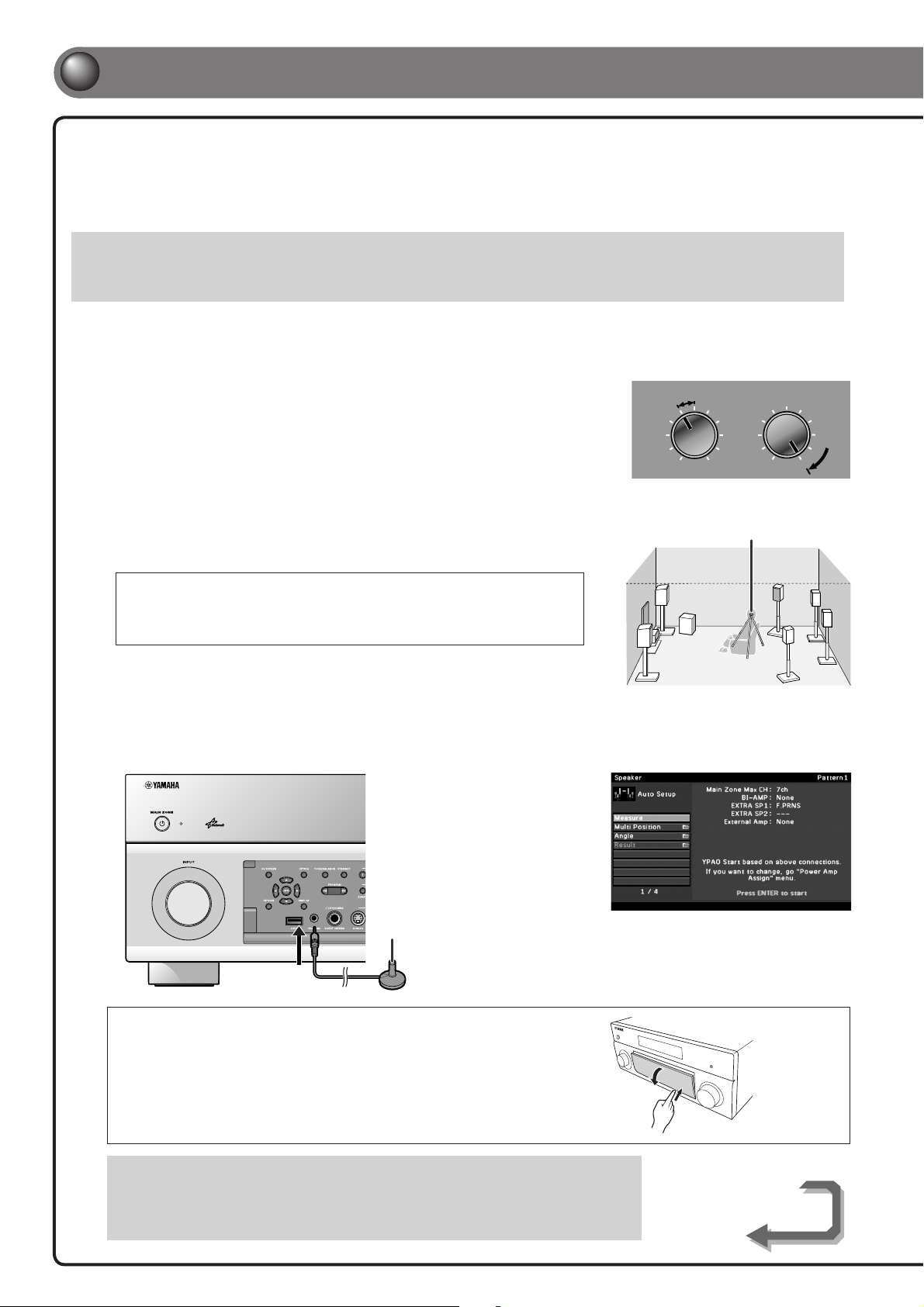
5
Set up the speaker parameters automatically (YPAO)
When all connections are complete, adjust the con guration, sizes, and volume
balance of the speakers to provide an optimal sound eld. This unit is equipped with a
Yamaha Parametric Room Acoustic Optimizer (YPAO) function that adjusts the speaker
balance automatically with a simple procedure.
Be aware of the following when using YPAO.
• The amount of time for measurement varies from about two to ten minutes according to settings.
• The test tone is output at high volume. Refrain from using this function at night when it may be a nuisance to others.
• Take care that the test tone does not frighten small children.
YPAO operations can be viewed on the front panel display or TV screen. TV display is used here to explain operation.
Check the following before using YPAO.
1
This unit
• The headphones are removed.
TV
• This unit is connected to the TV correctly.
• The power is turned on.
• The video input to which the video output
from this unit has been selected.
Subwoofer
• The power is turned on.
• Volume is set to approximately half, and the
cross-over frequency (if present) is set to
maximum.
VOLUME
MIN MAX
Subwoofer examples
CROSSOVER/
HIGH CUT
MIN MAX
Place the supplied YPAO microphone at ear height in your listening
2
position.
• When positioning the microphone, we recommend that you use equipment that allows you
to adjust the height (such as a tripod) as a microphone stand. When using a tripod, use the
tripod screws to x the microphone in place.
• Measuring, for multiple listening positions, is also available. For more information, refer to
“Setting up the speaker parameters automatically (YPAO)” in the Owner’s Manual.
Press RECEIVER A on the remote control to switch this unit on.
3
Connect the YPAO microphone to the YPAO MIC jack on the front panel.
4
“Mic On View ON SCREEN”
appears on the front panel
display, and the display at right
appears on the TV screen.
YPAO can be performed viewing
only front panel display on this
unit without the TV screen.
YPAO microphone
YPAO microphone
Opening and closing the front panel door
Before step 4, gently press the bottom of the door to open it.
Keep the door closed when not using controls or jacks behind the front
panel door.
This completes preparation. To achieve more accurate results, take note of the following when
measuring acoustics.
• Keep the room as quiet as possible for a few minutes.
• Wait in a corner of the room, or leave it entirely, while acoustics are measured to avoid creating
an obstruction between the speakers and the YPAO microphone.
- 6 -
Continues to
the next page
Page 7
/
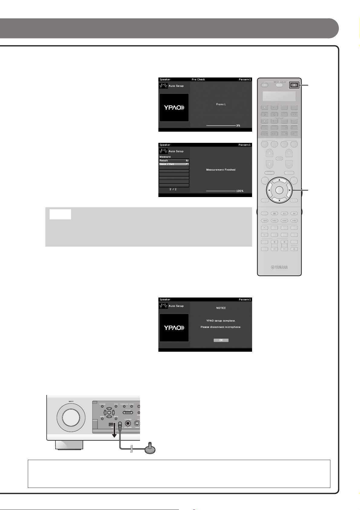
Use the cursor B/C to select the “Measure” and press ENTER to start
5
measurement.
When “Multi Position” and/or “Angle” is set to “Yes”
(default), the measurement of Multi Position and/
or Angle continues. Refer to “Setting up the speaker
parameters automatically (YPAO)” for details on
“Multi Position” and “Angle” in the Owner’s Manual.
The display at right appears if measurement nishes
without any problems.
Result
Displays the results of automatic acoustics
measurement. For details, refer to “Reviewing the
automatic setup parameters” in the Owner’s Manual.
Save/Exit
Applies the result to the speaker setup and nishes
the automatic measurement.
SOURCE
RECEIVER
AV
75 6
AUDIO
USB
MULTI
PHONO
TUNER
DOCK
1
ON SCREEN
RETURN DISPLAY
PROGRAM
TOP MENU
SIRIUS
SCENE
2
3
MUTE
VOLUME
POP-UP/MENU
ENTER
V-AUX
NET
[ A ]
OPTION
4
431 2
431 2
4
RECEIVER A
ENTER, Cursor
Note
If a problem occurs, an error message or report is displayed either during or after acoustic
measurement. Refer to “When an error message is displayed during measurement,” or “When a
warning message is displayed after measurement” in the Owner’s Manual to resolve the problem
and measure acoustics with YPAO again.
Use the cursor B/C to select “Save/Exit” and press ENTER.
6
Use the cursor D/E to select “SAVE” and press ENTER.
7
When the display at right appears, the YPAO setup is
complete.
Press ENTER.
8
YPAO is terminated. Disconnect the YPAO microphone.
REC
HOLD TAG PRG SELECT
LIVE
CLASSICAL
MOVIE
TV
TV VOL TV CH
CLUB
STEREO
PRESET
INPUT
MUTE
ENTERTAIN
STRAIGHT
PURE
DIRECT
All the preparation is completed.
Enjoy the various functions provided by this unit. For details on the operations, refer to the Owner’s
Manual.
- 7 -
Page 8
Basic operations
PHONO
DOCK
1
PROGRAM
MULTI
TUNER
SOURCE
2
6
2
2
AUDIO
SCENE
AV
MUTE
RECEIVER
31
75
31
USB
SIRIUS
3
VOLUME
V-AUX
NET
[ A ]
4
4
4
4
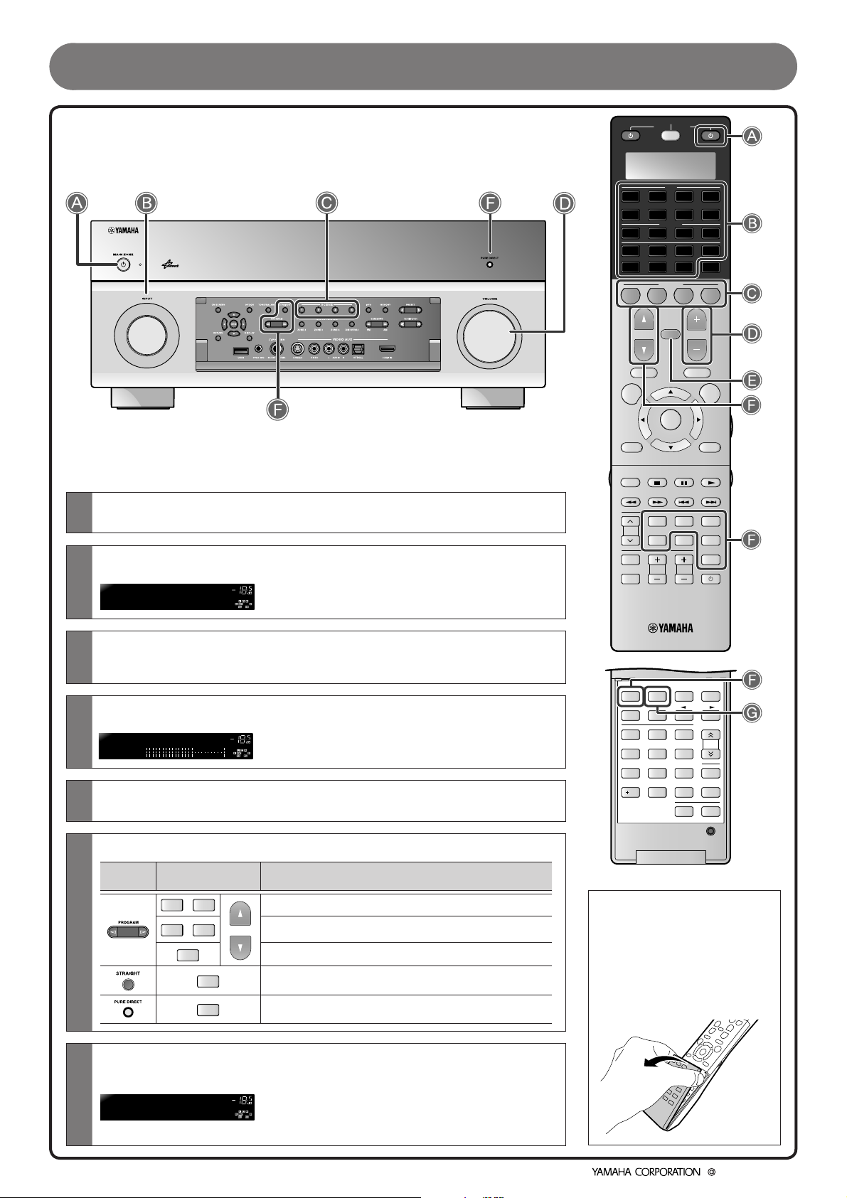
A
Switches this unit between on and standby mode
This unit switches between on and standby mode every time you press this key.
B
Selects an input source to listen to
The name of the selected input source appears on the front panel display.
C
Selects a scene
You can switch the settings such as input sources and sound eld programs with a single key. Refer to
“Default scene settings” on page 5 for details on the settings assigned to this unit.
Adjusts the volume level
D
The current volume level is displayed on the front panel display.
E
Mutes the sound
The MUTE indicator blinks while the sound is muted.
ENTER
CLASSICAL
MOVIE
TV
TV VOL TV CH
ENHANCER
MEMORY
21
5
8
0
POP-UP/MENU
LIVE
CLUB
STEREO
PARTY
FM
3
6
9
ENT
ZONE
CATEGORY
OPTION
ENTERTAIN
STRAIGHT
DIRECT
HDMI OUT
TUN./CH
SLEEP
LEVEL
SETUP
TOP MENU
ON SCREEN
RETURN DISPLAY
REC
HOLD TAG PRG SELECT
PRESET
INPUT
MUTE
SUR.
DECODE
INFO
4
7
10
PURE
AM
F
Selects sound eld programs and sound decoders
Front
panel
G
Turns on Compressed Music Enhancer
Press ENHANCER to turn on Compressed Music Enhancer for playback of the compressed music
source with better sound quality.
To disable Compressed Music Enhancer, press ENHANCER again.
© 2010 Yamaha Corporation
Remote control Description
LIVE
CLASSICAL
ENTERTAIN
DECODE
SUR.
CLUB
MOVIE
STRAIGHT
PURE
DIRECT
Selects sound eld programs optimized for appreciating music.
Selects sound eld programs optimized for viewing movies,
PROGRAM
dramas, and sports.
Selects surround decoders such as Dolby Pro Logic II.
Switches to Straight decoding mode for stereo/multi-channel
playback without using a sound eld program.
Switches to Pure Direct Mode for faithful reproduction of audio.
- 8 -
Opening the remote
control cover
Hold the tabs on the sides
of the remote control with
your ngers, and pull the
cover to open.
YC713A0/QREN1
 Loading...