

Page 1
Page 2
●
Precautions
Do not expose the plug-in board to direct sunlight,
excessive humidity, high temperatures, excessive dust
or strong vibrations.
●
Before handling the plug-in board, be sure to touch a
metal surface to discharge any static electricity which
may be in your body.
●
When holding the plug-in board, do not touch the inside
area of the circuit board or apply excessive pressure to
the board, and be sure to protect the board from contact
with water or other liquids.
●
Before installing the plug-in board onto a tone generator/sound card, unplug the power connector of your
computer.
* The company names and product names in this Owner’s Manual are the trademarks or re gistered
trademarks of their respective companies.
* The screens as illustrated in this owner’s manual are for instructional purposes only, and may
appear somewhat different from the ones of your instrument.
●
Before connecting the computer to other devices, turn
off the power switches of all devices.
●
Yamaha is not responsible for loss of data through computer malfunctions or operator actions.
●
The plug-in board contains no user-serviceable parts, so
never touch the inside area of the circuit board or
tamper with the electronic circuitry in any way. Doing
so may result in electrical shock or damage to the plugin board.
YAMAHA CANNOT BE HELD RESPONSIBLE
FOR DAMAGE CAUSED BY IMPROPER
CARE AND USE OF THE PLUG-IN BOARD.
FCC INFORMATION (U.S.A.)
1. IMPORTANT NOTICE: DO NOT MODIFY THIS UNIT!
This product, when installed as indicated in the instructions contained in this manual, meets FCC requirements. Modifications
not expressly approved by Yamaha may void your authority, granted by the FCC, to use the product.
2. IMPORTANT:
Cable/s supplied with this product MUST be used. Follow all installation instructions. Failure to follow instructions could void
your FCC authorization to use this product in the USA.
3. NOTE:
”B” digital devices. Compliance with these requirements provides a reasonable level of assurance that your use of this product
in a residential environment will not result in harmful interference with other electronic devices. This equipment generates/uses
radio frequencies and, if not installed and used according to the instructions found in the users manual, may cause interference
harmful to the operation of other electronic devices. Compliance with FCC regulations does not guarantee that interference will
not occur in all installations. If this product is found to be the source of interference , which can be determined by turning the unit
”OFF” and ”ON”, please try to eliminate the problem by using one of the following measures:
Relocate either this product or the device that is being affected by the interference.
Utilize power outlets that are on different branch (circuit breaker or fuse) circuits or install AC line filter/s.
In the case of radio or TV interference, relocate/reorient the antenna. If the antenna lead-in is 300 ohm ribbon lead, change the
lead-in to co-axial type cable.
If these corrective measures do not produce satisfactory results, please contact the local retailer authorized to distribute this
type of product. If you can not locate the appropriate, please contact Yamaha Corporation of America, Electronic Service Division, 6600 Orangethorpe Ave, Buena Park, CA 90620
* This applies only to products distributed by YAMAHA CORPORATION OF AMERICA.
When connecting this product to accessories and/or another product use only high quality shielded cables.
This product has been tested and found to comply with the requirements listed in FCC Regulations, Part 15 for Class
CANADA
This Class B digital apparatus complies with Canadian ICES-003.
Cet appareil numérique de la classe B est conforme à la norme NMB-003 du Canada.
• This applies only to products distributed by Yamaha Canada Music Ltd.
• Ceci ne s’applique qu’aux produits distribués par Yamaha Canada Musique Ltée.
2
Page 3

3
Congratulations and thank you for purchasing the Yamaha PLG150-DX Advanced DX/TX Plugin Board!
The PLG150-DX features the same 6-operator FM tone generation system that powered the
famous DX-series synthesizers. The PLG150-DX can be installed to and integr ated with instruments of the Modular Synthesis Plug-in System (such as the CS6x, CS6R, S80, etc.) It can
also be used seamlessly with the MU128 Tone Generator (as well as other MU-series instruments and the SW1000XG PCI Audio/MIDI Board). Once it’s installed, the PLG150-DX puts
the dynamic and flexible sound of FM synthesis right at your fingertips, with a total 912 DXseries voices.
The settings and parameters of the PLG150-DX can also be conveniently edited via MIDI with a
Windows PC computer by using the DX Easy Editor and DX Simulator software modules
(included in the XGworks Music Sequencer software).
To install your PLG150-DX correctly and to ensure full enjoyment of its sophisticated functions,
be sure to read this manual very carefully. When finished, keep the manual in a secure and
convenient place for future reference.
Table of Contents
Overview of the PLG150-DX
FM Tone Generation
Operators..............................................................6
Combinations of Two Operators...........................7
Carrier and Modulator...........................................8
Harmonics ............................................................9
Algorithms...........................................................10
Feedback............................................................11
Voice Editing Essentials.....................................12
...................................................6
Memory Buffer Structure
Specifications
............................................................15
About the Included CD-ROM and Floppy Disk
Installing the PLG150-DX
Included Items
...........................................................18
Required and Recommended Items
Synthesizer/Tone Generator/
Sound Card Compatible with the Modular
Synthesis or XG Plug-in Systems..................18
XGworks or XGworks lite
Music Sequencing Software..........................19
DX Easy Editor...................................................19
DX Simulator ......................................................19
Installing and Starting the Plug-in
Editor Software (Windows 95/98)
Installing the Software........................................20
Starting the DX Easy Editor................................20
Starting the DX Simulator...................................21
.....................................4
......................................14
.........................................18
.......................18
...................20
.......16
Selecting DX Voices
(Modular Synthesis Plug-in System)
Enabling and Selecting DX Voices .................... 22
................ 22
Editing the DX Native Part Parameters
(Modular Synthesis Plug-in System)
................ 23
Selecting/Editing the DX System Parameters
(Modular Synthesis Plug-in System)
Selecting DX Voices (XG Plug-in System)
Enabling and Selecting DX Voices .................... 25
................ 24
............ 25
Editing the DX Native Part Parameters
(XG Plug-in System)
............................................. 27
Selecting/Editing the DX System Parameters
(XG Plug-in System)
Parameters
DX Native Part Parameters................................ 29
DX System Parameters ..................................... 32
Appendix
Chart of Algorithms
Voice List
DX Parameter List
(XG / Modular Synthesis Plug-in System)
MIDI Data Format
When Your PLG150-DX
Seems to Have a Problem
MIDI Implementation Chart
.............................................................. 29
.................................................................... 34
............................................................... 36
............................................. 28
............................................. 34
.................................................. 47
............................... 57
................................. 60
.... 46
Page 4

■
■
■
■
Overview of the PLG150-DX
FM Synthesis
The PLG150-DX employs the same FM tone generation system — with 6 operators and 32 algorithms — as made famous by the popular DX-series synthesizers.
912 Preset Voices
Built right into the PLG150-DX is a huge total of 912 DX voices. From conventional instrument
sounds such as electric piano and bass to wild and unusual sound effects, the PLG150-DX gives you
the full range of voices that made the DX-series instruments famous.
16-note Polyphony
The PLG150-DX features a maximum polyphony of 16 notes, the same as on the DX7 and DX7II.
However, unlike with those instruments, you can install multiple PLG150-DX boards (up to a maximum of eight) for a total polyphony of 128 notes. For example, when three PLG150-DX boards are
installed to a MU128 tone generator, the maximum polyphony becomes 48 voices.
■
Voice Data Transfer
Since the PLG150-DX is compatible with the DX-series instruments, voice data can be transferred
between the plug-in board and the DX7 or DX7II. This allows you to use those instruments (or compatible editing software) to edit and create voices, which can then be transferred to the PLG150-DX.
The PLG150-DX is also compatible with voice parameters for the DX1, DX7S, TF1 modules (such as
for the TX816), TX7, and the TX802.
Some voices on the compatible devices mentioned above may sound slightly different when played on
the PLG150-DX.
Built-in Filters and Equalizer
The PLG150-DX gives you additional sound-shaping power with built-in low pass and high pass filters, plus a two-band equalizer. You can use these together with other FM voice parameters to create
your own original voices.
4
Page 5
Overview of the PLG150-DX
About the Modular Synthesis Plug-in System
The Yamaha Modular Synthesis Plug-in System offers powerful expansion and upgrade capabilities for Modular Synthesis-Plug-in-compatible synthesizers, tone generators and sound cards.
This enables you to easily and effectively take advantage of the latest and most sophisticated
synthesizer and effects technology, allowing you to keep pace with the rapid and multi-faceted
advances in modern music production.
About the XG Plug-in System
The Yamaha XG Plug-in System offers powerful expansion and upgrade capabilities for XGPlug-in-compatible tone generators and sound cards. This enables you to easily and effectively
take advantage of the latest and most sophisticated synthesizer and effects technology, allowing
you to keep pace with the rapid and multi-faceted advances in modern music production.
5
Page 6
FM Tone Generation
Before actually editing the PLG150-DX voices , let’ s get an idea of ho w the FM tone generator works.
Operators
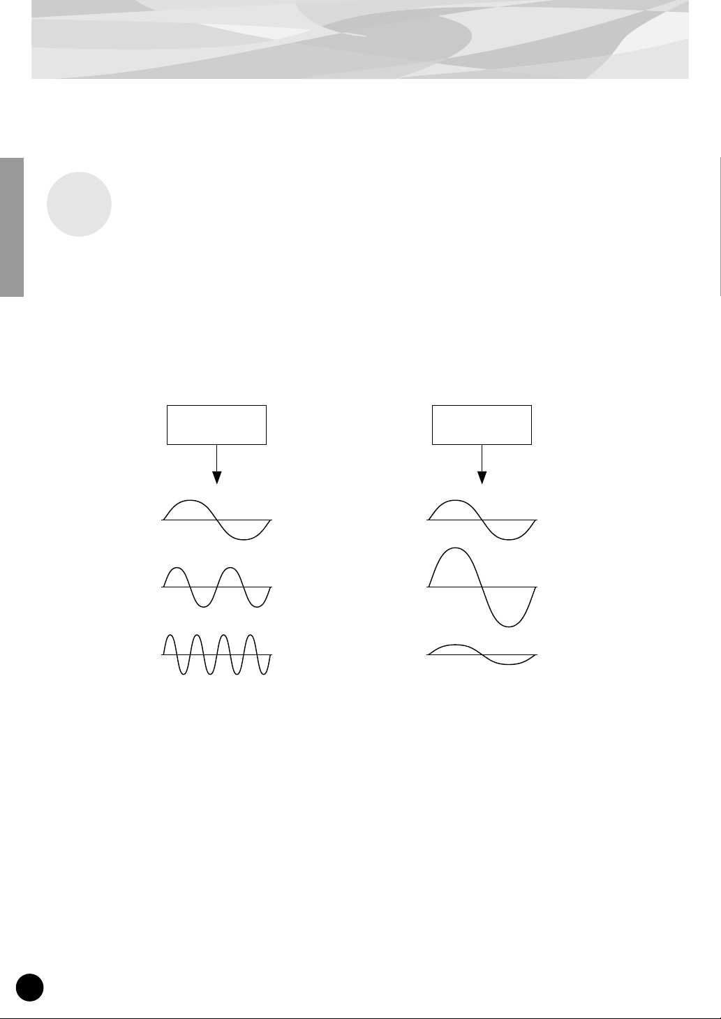
In the PLG150-DX, there are six special devices called “operators” that generate sine waves. A sine
wave is the fundamental wave of a note, with absolutely no overtones or harmonics added. These six
operators are combined in various ways to make up the dif ferent v oices produced by the PLG150-DX.
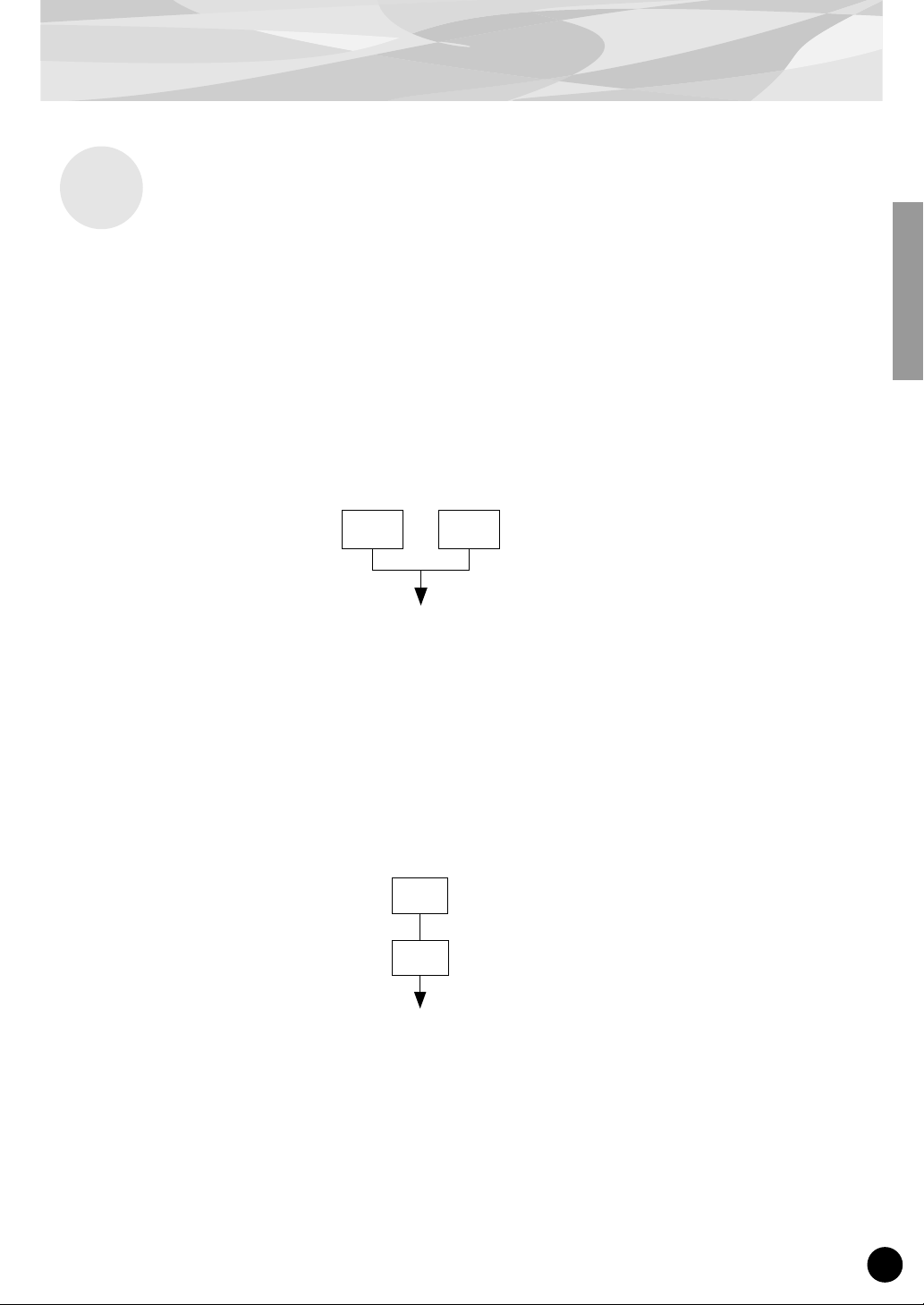
The operators can be used to freely change two different aspects of the sound:
(1) The frequency (pitch) of the generated sine wave.
(2) The amplitude (volume or output level) of the generated sine wave.
Operator Operator
The frequency of the
sine wave is changed.
This results in the pitch
becoming higher or
lower.
The amplitude of the
sine wave is changed.
This results in the volume
becoming higher or lower.
6
Page 7
Combinations of Two Operators
Although the six operators can be combined in a wide variety of ways for many dif ferent sounds, here
we’ll look at the fundamental combinations of just two operators, to help you understand the basics of
FM synthesis.
Two sine wave operators (labelled “A” and “B” here) can be combined in one of two ways: horizontally or vertically.
(1) Horizontal Combination
When the two operators are combined horizontally, the sounds of the two are simply mixed together.
This combining of two or more different sounds is called additive synthesis.
FM Tone Generation
A B
Mixed sound of A and B
(2) Vertical Combination
When the two operators are combined vertically, the sound of the top operator (B) “modulates” that of
the lower operator (A). In this situation, operator B produces no sound, but alters the sound of operator A, producing a sound of greater harmonic complexity. This “stacking” of operators is called Frequency Modulation (FM) synthesis.
Operator B changes or modulates the sound
B
of A (but produces no sound itself).
Operator A produces the actual sound, as
A
modulated by B.
T o sum it up, when tw o operators are combined horizontally, both operators generate the sound; when
combined vertically, one operator changes the sound, the other produces it.
7
Page 8
FM Tone Generation
Carrier and Modulator
In FM tone generation, each of the six operators functions as either a carrier or a modulator. The
operator doing the modulation is called the modulator; the one being modulated and delivering the
actual sound is called the carrier. Referring back to “Vertical Combination” on the previous page,
operator A is the carrier and operator B is the modulator.
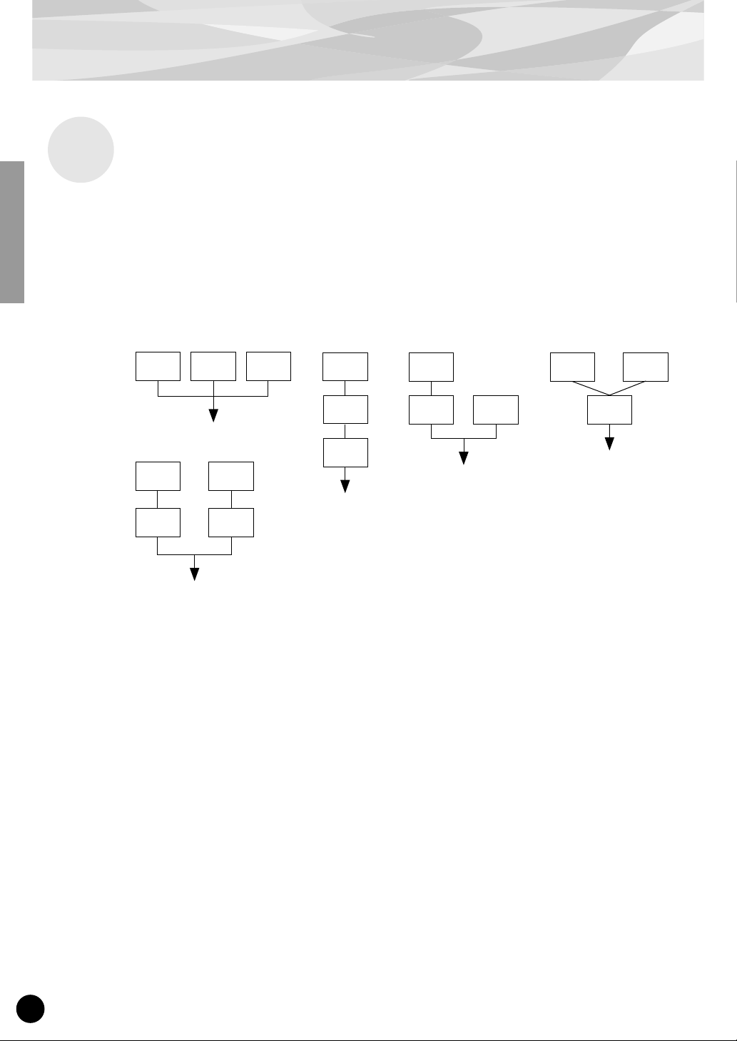
Let’s take a look at some more complex configurations, in which three or more operators are used.
Keep in mind that the modulator/carrier function is the same in all examples.
fig. 1
C C C
fig. 5
fig. 2
M
M
fig. 3 fig. 4
M
C
C
M M
C
C
M M
C C
“C” Carrier
“M” Modulator
●
In fig. 1, all operators are combined horizontally and there are no modulators, only carriers. Without modulation, all carriers output simple sine waves.
●
In fig. 2, three operators are stacked vertically, and only the lowest is a carrier. The top operator
modulates the middle one, which in turn modulates the carrier at the bottom. This results in a complex waveform, with many harmonics or overtones. (An explanation of harmonics follows on the
next page.)
●
In fig. 3, there are two carriers and one modulator. The sole carrier on the right produces a simple
sine wave, while the modulator/carrier pair on the left produce a more complex waveform with
added harmonics. The actual sound is a mix of the two carriers.
●
In fig. 4, two modulators are used change the sound of a single carrier. Using two modulators produces an even more complex sound than is possible with one, with a greater amount of harmonics.
●
In fig. 5, there are two modulator/carrier pairs, each generating a complex sound with many harmonics. As with the operators in fig. 3, the actual sound is a mix of the two carriers.
8
Page 9
Harmonics
Most sounds are made up of multiple tones that are different than the pitch (frequency). Within these
multiple tones, the one that determines the pitch of the entire sound is called the fundamental tone
(fundamental frequency). All the tones besides the fundamental tone are called harmonics or overtones.
When all the harmonics that are related to a particular fundamental tone are arranged in order, it is
called a harmonic series. Each tone in the harmonic series is given a name in order, with the fundamental tone being one, followed by the second harmonic, third harmonic and so on.
The frequency of each harmonic in the harmonic series is a natural number multiple of the frequency
of the fundamental tone. Overtones that have frequencies that are not natural number multiples of the
fundamental are called unharmonic overtones.
FM Tone Generation
Generally, the more harmonics the tone has, the brighter the sound. On the other hand, if the amount
of harmonics is reduced, the tone will sound darker. Furthermore, the voice will change a lot according to the type and volume of the harmonics. For example, if there are a lot of high pitched harmonics
in the tone, it will have a brilliant, crisp sound. On the other hand, a tone with a large amount of lower
harmonics will have a rather “fat,” warm sound.
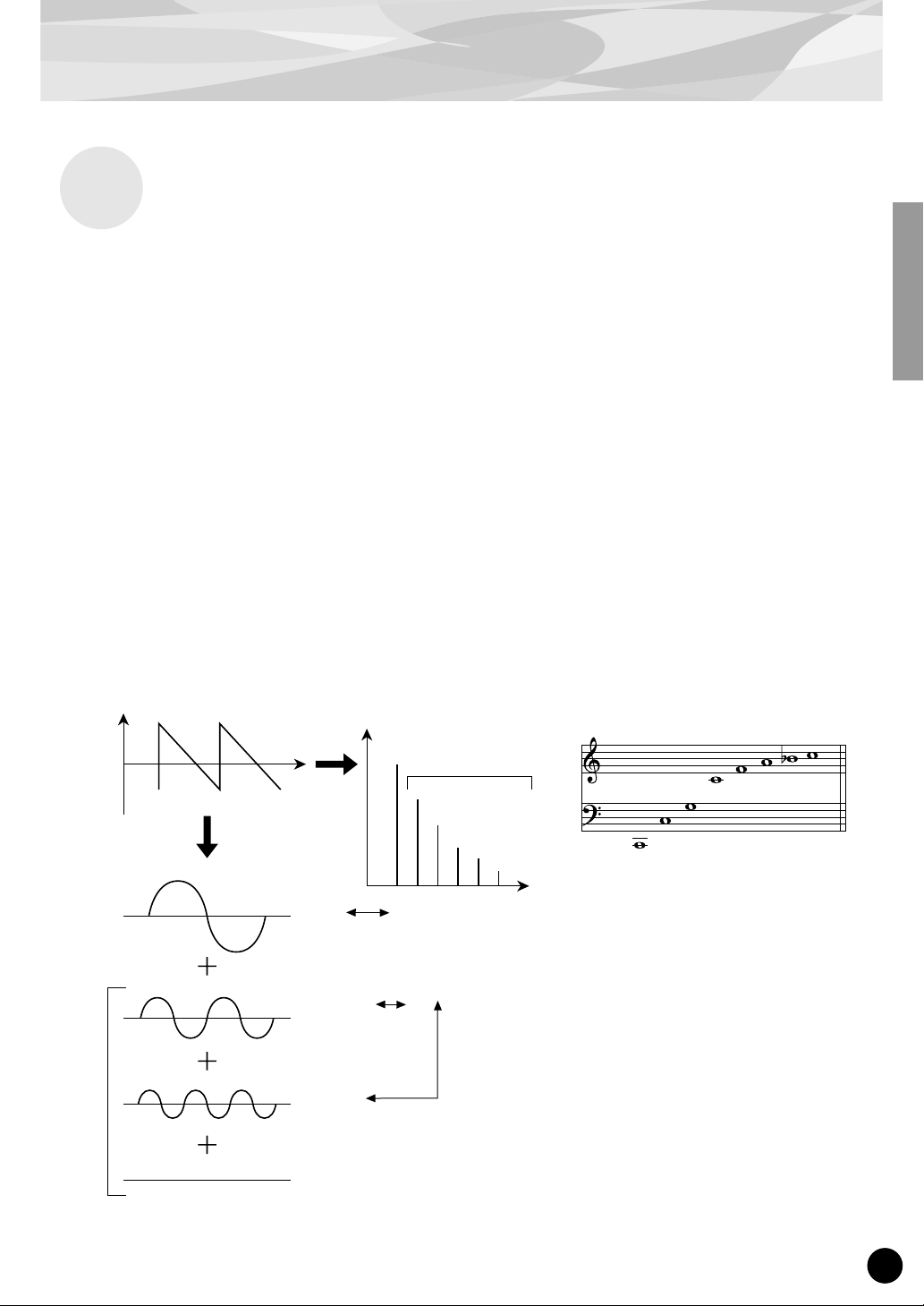
Harmonics
Level
Waveform
Fundamental Wave
Second Harmonic
Time
Level
Fundamental and
Harmonics (graph)
Harmonics
Fourth Harmonic
Third Harmonic
Second Harmonic
Fundamental
Frequency
Natural Harmonic Series
(when C1 is the fundamental tone)
Fifth Harmonic
Fourth Harmonic
Third Harmonic
Second Harmonic
Fundamental
Sixth Harmonic
Seventh Harmonic
Eighth Harmonic
Harmonic
Third Harmonic
9
Page 10
FM Tone Generation
Algorithms
Although two operators can be combined in only two different ways, six operators can be configured
in a wide variety of combinations. These combinations are called “algorithms.” Just as on the original DX7, the PLG150-DX features 32 different algorithms, giving you different levels of harmonic
complexity for various applications.
Since the function of any given operator depends on the particular algorithm, you should check a
voice’s algorithm carefully while editing the voice. For a chart showing all 32 algorithms, see page
34. Each operator in the algorithm is numbered to distinguish it from the others in editing.
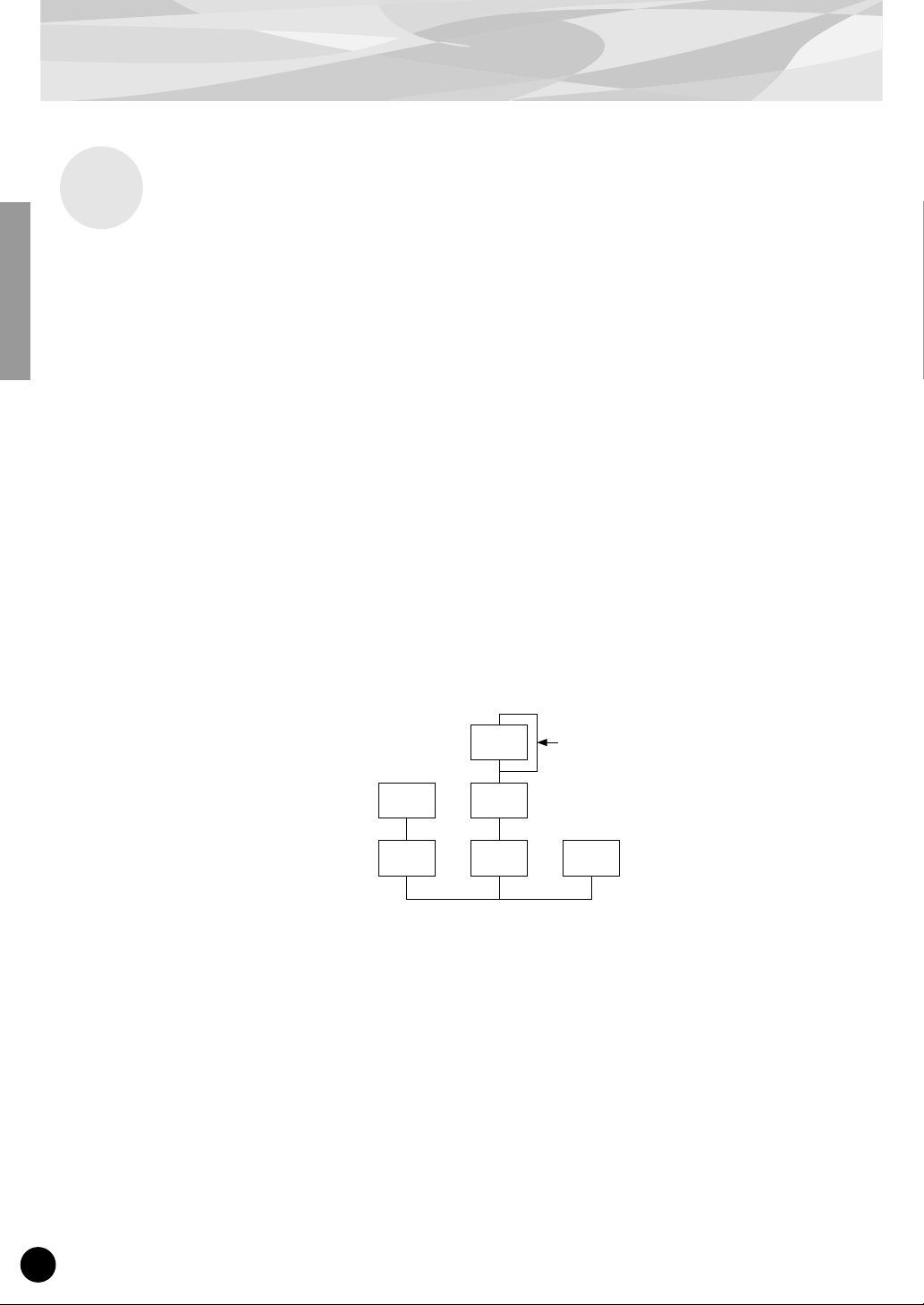
Let’s take a look at algorithm 28 as an example. The various operators function as follows:
Operator 1.............Carrier; is modulated by Operator 2, and outputs the resulting sound.
Operator 2.............Modulator; modulates Operator 1.
Operator 3.............Carrier; is modulated by Operator 4, and outputs the resulting sound.
Operator 4.............Modulator; modulates Operator 3.
Operator 5.............Modulator; modulates itself with a feedback loop, and modulates
Operator 6.............Carrier; outputs a sine wave.
Operator 4.
Algorithm 28
2 4
1 3 6
5
Feedback loop
(see next section)
10
Page 11
Feedback
Each algorithm has a special feedback loop, programmed to a fixed location in the algorithm. With
feedback, a modulator’s output is connected to its own input, so that it modulates itself. This can be
used to increase the harmonic content of the sound, making it more rich and complex. When set to a
high level, feedback can generate noise effects — making it useful for percussive voices, metallic
sounds, and distortion effects.
Some algorithms feature a feedback loop that takes in two or three operators as a group. One such
example is algorithm 4 shown below, in which the output of operator 4 is returned to the input of
operator 6, thus modulating the entire stack. This provides even greater possibilities for tonal variation and richness.
FM Tone Generation
Algorithm 4
3
2
1
6
5
4
Feedback loop
11
Page 12

FM Tone Generation
Voice Editing Essentials
There are four main elements that determine the character of a voice:
(1) Each operator’s output level.
(2) Each operator’s frequency.
(3) The feedback level.
(4) Each operator’s envelope generator (EG).
(1) Operator Output Level
The output levels of the operators are the most important parameters in editing a voice. Among these,
the output level of the modulator(s) has the greatest effect on the timbre or tonal quality of the voice.
If a modulator’s output level is set to “0” so that it does not modulate the carrier, the resulting output
of the carrier will be a simple sine wave (belo w). Increasing the output of the modulator increases the
degree of modulation and, hence, the amount of harmonics in the sound. Generally, the greater the
modulator’s output, the brighter the sound will be. Extremely high values result in a harsh, noisy
sound.
Modulator
Carrier
Since the carrier actually produces the sound, increasing the output level of a carrier increases the volume of the sound. If there are two or more carriers, changing the output level of individual carriers
may also affect the timbre of the sound, since the volume balance of the different carriers is changed.
B
Output Level = 0
A
Sine wave The waveform changes
B
The output level is
increased slightly.
A
slightly.
B
The output level is
greatly increased.
A
The waveform changes a lot.
(2) Operator Output Frequency
The type of harmonics added to the carrier output by means of the modulator is determined by the
ratio between the frequencies of the modulator and carrier. F or e xample, when two operators are combined vertically, and “F COARSE” for both of them is set to 1.00, the frequency ratio will be 1:1 and
the first, second, third and following whole number series harmonics will be generated in order. This
type of harmonic configuration is called a sawtooth wave, and is used for making voices like brass,
strings, or piano.
12
Page 13

FM Tone Generation
If the “F COARSE” for the modulation in this situation is changed to 2.00, the frequency ratio
becomes 1:2, and the odd numbered harmonics, the first, third and fifth and following harmonics will
be generated. This harmonic configuration is called a rectangular wave, and is used for creating w oodwind voices for like clarinet and oboe.
Furthermore, if “F FINE” is set so that the frequency ratio is not a whole number, many non-integer
overtones will be produced. The sound can be used for creating metallic sounds, the noise when
strings are hit with something, or breath noise.
Modulator
Carrier
B
Frequency
ratio 1:1
A
Sawtooth wave Rectangular wave
B
Frequency
ratio 1:2
A
(3) Feedback Level
As we saw earlier, feedback is a function in which a modulator’s output is connected to its own input,
so that it modulates itself. Increasing the feedback level increases the harmonic content of the sound,
making it brighter and complex. Keep in mind that the total effect also depends on the output level of
the feedback-applied operator; if that operator’s output level is set to “0,” feedback level will have no
affect on the sound.
(4) EG (Envelope Generator)
The EG (Envelope Generator) parameters allow you to shape the sound of the voice. In other words,
these determine how the level of the voice changes over time, from when a key on the keyboard is
played until it is released and the sound dies out.
The EG parameters let you reproduce the sound of acoustic instruments, and their natural patterns of
attack, sustain and decay. For example, the sound of a piano has a very sharp attack and a moderately
long sustain: The sound gets loud the instant a key is played, and gradually fades away as the key is
held. The tone or timbre of the sound also changes in time, with the sound starting out very bright and
gradually growing warmer and softer (as the harmonics start to fade).
Since each operator has its own EG, the PLG150-DX gives you comprehensive and dynamic control
over both the volume and timbre of the voice, letting you accurately reproduce these natural acoustic
effects. The carrier EGs af fect the volume of the sound over time, while the modulator EGs affect the
timbre.
13
Page 14

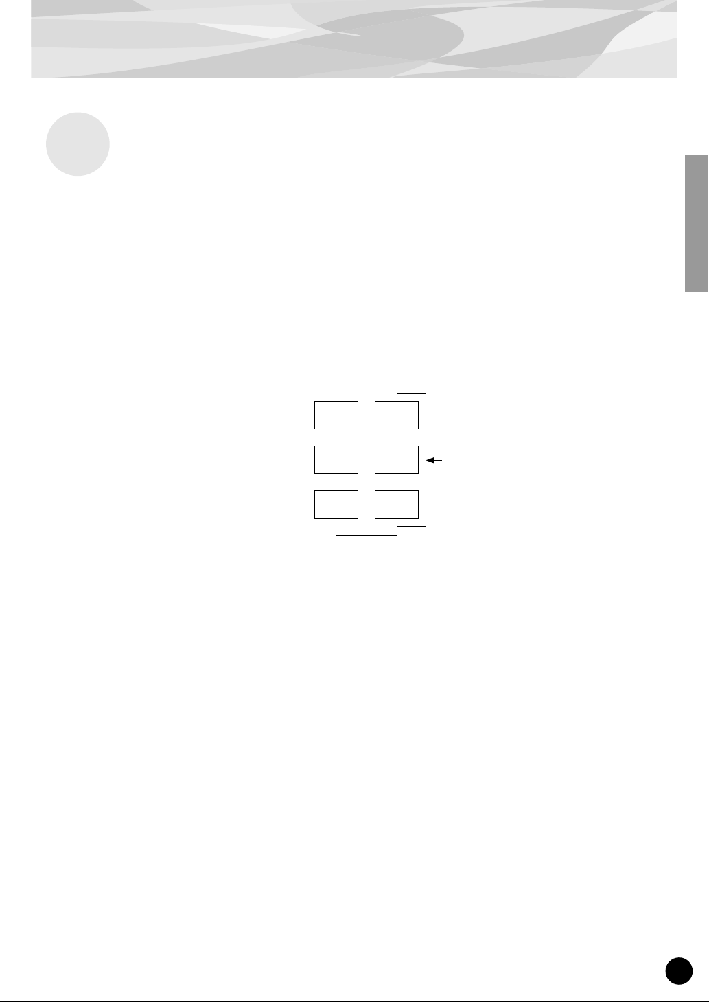
Memory Buffer Structure
The diagram below shows the memory buffer configuration of the PLG150-DX.
Recall
Voice Edit Buffer
Compare
Edit Recall
Edit Recall Buffer
When editing the voices (using the DX Simulator), only the User voices can be fully edited; Preset voices can be edited only as far as the XG and DX Native Part parameters.
When Using the User voices:
• When a DX voice is selected from one of the User voices, the DX voice’s settings for the following
parameters take precedence over the corresponding settings.
XG Native Part Parameters
Mono/Poly Mode
Pitch Bend Control
Portamento Switch
Portamento Time
PLG150-DX Native Part Parameters
Pitch Bend Step
Portamento Step
Portamento Mode
In other words, the settings of these XG Part parameters (on an MU128, etc.) are replaced by those
of the selected DX voice. Naturally, once the voice is selected, the Part parameter values can then
be changed from the panel of the XG-compatible “mother” device (MU128, etc.). The XG Native
Part parameters can also be changed by appropriate parameter change messages.
• If an XG System On is received, or part assignment is changed, the User voices will be initialized,
but the 64 voice VMEM and AMEM areas will not be initialized.
Store
Preset Memory
(912 Voices)
User Voices
(64 Voices)
14
Page 15

Specifications
Tone Generator Type : FM tone generator with six operators and 32 algorithms
Maximum Simultaneous Polyphony :
Filters : Part EQ (two band), low pass filter, high pass filter (effective only when
Interface : Plug-in connector
Number of Voices : 912 preset voices, 64 user voices
Bulk Information that Can Be Received from Other Devices :
Parameter Changes that Can Be Received from Other Devices :
16 notes (latest note priority)
By using multiple boards in combination, polyphony can be expanded to
a maximum of 128 notes (with 8 boards)
the platform for the PLG150-DX has no filter functions)
DX7 Voice Edit Buffer, Packed 32 Voice
DX7II Voice Edit Buffer, Packed 32 voice, a portion of the Additional
Edit Buffer, a portion of the Packed 32 Additional (Pitch EG
range, rs, velocity switch, Unison detune, AMS, Random pitch,
Poly/Mono, Unison Sw, Pitch bend range, step, Portamento
mode, step, time)
DX7 VCED, a portion of ACED (Pitch EG range, rs, velocity switch, Unison detune, AMS, Random pitch, Poly/Mono, Unison Sw, Pitch bend
range, step, Portamento mode, step, time)
Dimensions (W x H x D) : 138.5 x 89.0 x 8.5mm
Weight : 63g
Included Items : Owner’s Manual, CD-ROM × 1
* Specifications subject to change without notice.
15
Page 16

About the Included CD-ROM and Floppy Disk
On the included CD-ROM, you’ll find special editing software for the PLG150-DX. The included
floppy disk contains demonstration songs as well as V oice/Performance data for the “mother” device.
To use the editing software and transf er the song/Voice/Performance data to your particular “mother”
device, you should have a computer (running Windows 95/98) with a MIDI interface, with the MIDI
OUT on the interface connected to the MIDI IN of the “mother” device. You should also have
XGworks (v3.0 or higher) or XGworks lite installed to your computer; this is necessary to use the
editing software (page 19). In order to use the editing software, insert the CD-ROM into the computer and start the installation.
For playing bac k the demonstr ation songs and tr ansferring the Voice/Performance data, you can use
any compatible sequence software (such as XGworks/XGworks lite) or hardware sequencer capable of sending bulk data.
The included CD-ROM contains the following software:
■ DX Easy Editor (page 19)
■ DX Simulator (page 19)
The included floppy disk contains the following software:
■ Demonstration Songs
“Many Colors of the DX7 system” (02Colors.MID)
By: Hirohiko Fukuda of Shofuku
For: Modular Synthesis Plug-in System devices (CS6x, etc.)
One of the strongest points of FM Synthesis is its ability to create complex overtones in real time. In this
song, system exclusive messages are used, in addition to velocity, to directly control the output of the
modulators. This creates an even greater variety of sound changes — allowing complex sound shaping
that just isn’t possible through wave sampling and conventional filter systems.
16
“The Soul Of DX” (12SoulDX.MID)
By: Minoru Mukaiya of Casiopea
For: XG Plug-in System devices (MU128, etc.)
This powerful song uses the crystal-clear sound of the DX7 with techno drums, and combines the XG
and DX systems to produce an extraordinarily dynamic sound.
“Ie Kia Bara Hein” (12IeKia.MID)
By: Noritaka Ubukata of Shofuku
For: XG Plug-in System devices (MU128, etc.)
The title of the song means “What kind of spell is this?” in the Hindi language. It features the voice that
simulates a santur (hammer dulcimer) together with a sitar.
“DX VOICE” (12Voice.MID)
By: Noritaka Ubukata of Shofuku
For: XG Plug-in System devices (MU128, etc.)
Starting with an electric piano sound, this song features a variety of popular voices used with the original
DX7. The changes in velocity produce subtle variations in the sound that cannot be accomplished with
sampling. Another special feature is the FM choir (starting around measure 43). You may want to try
mix this sound with an actual human voice or choir — for example, by using the data in track 1 to also
play a connected sampler — you can get a much more dynamic and realistic choir sound.
“Vel&EffectWorks1” (12V_EfW1.MID)
“Vel&EffectWorks2” (12V_EfW2.MID)
“DX Short Demo” (12ShtDM.MID)
By: Yasuhiko Fukuda of Shofuku
For: XG Plug-in System devices (MU128, etc.)
These songs showcase the unique ability of FM Synthesis to use velocity to produce dramatic changes in
the sound.
Page 17

About the Included CD-ROM and Floppy Disk
“80’s Pops” (12Pop80.MID)
By: Katsumi Nagae of Idecs Inc.
For: XG Plug-in System devices (MU128, etc.)
This song recalls the pop scene of the 80’s with synth pads and a variety of crisp and bright metallic
sounds.
“D-Rock” (12DRock.MID)
By: Katsumi Nagae of Idecs Inc.
For: XG Plug-in System devices (MU128, etc.)
This song brings back the digital rock sound and features various digital noise and FM sound effects that
are only possible with the DX.
“EP Ballade” (12Ep.MID)
By: Katsumi Nagae of Idecs Inc.
For: XG Plug-in System devices (MU128, etc.)
If it’s ballads you want-well, there is nothing like DX electric piano.
The voice in the electric piano part will also work with different electric pianos. Try playing the song
with different piano voices.
“House” (12House.MID)
By: Katsumi Nagae of Idecs Inc.
For: XG Plug-in System devices (MU128, etc.)
The typical house music sound is simulated in this song, which experiments with reproducing sampling
phrases using the DX Voice system. In addition, the second half of the song features the metalic sound
that is a strong point of the DX.
“Jungle” (12Jungle.MID)
By: Katsumi Nagae of Idecs Inc.
For: XG Plug-in System devices (MU128, etc.)
This song adds a touch of Chinese feeling to the Jungle. The Oriental image is underscored by the
“CHINA_S&” and “IMAGE9” plug-in SE voices.
If no sounds are played, or if you experience other problems with playback, see Appendix “When Your
PLG150-DX Seems to Have a Problem.”
■ Plug-in Voice Data for the CS6x/CS6R/S80
(Modular Synthesis Plug-in System)
This is Plug-in voice data, featuring a total of 64 voices that were created using the PLG150-DX Preset voices.
When the PLG150-DX is installed to PLG1, select the file “01PlgVc1.mid”; when the board is installed to PLG2,
select the file “01PlgVc2.mid”.
For a complete list of these voices, refer to the Plug-in Voice List in the Owner’s Manual.
■ Performance Data for the MU128/MU100/MU100R (XG Plug-in System)
This is Performance data, featuring a total of 64 Performances that were created using the PLG150-DX Preset
voices (“11Perf.MID”).
For a complete list of these Performances, refer to the Performance List in the Owner’s Manual.
17
Page 18

Installing the PLG150-DX
For detailed instructions on installing the PLG150-DX, refer to the owner’s manual of the Plug-incompatible “mother” device (e.g., CS6x, MU128, etc.).
Included Items
The following items have been included in the package of your new PLG150-DX. Please make sure
that you have them all before starting to setup and use the instrument. If an item is missing, contact
the store or dealer from which you purchased the PLG150-DX.
• PLG150-DX board
• PLG150-DX Owner’s Manual (this book)
• CD-ROM
• Floppy Disk
Required and Recommended Items
In addition to the included items listed above, you should also have the following:
Synthesizer/Tone Generator/Sound Card Compatible with the
Modular Synthesis or XG Plug-in Systems
In order to use the PLG150-DX, you’ll need a synthesizer, tone generator or sound card compatile
with the Modular Synthesis Plug-in System or the XG Plug-in System. Compatible instruments
include the CS6x, MU128, and the SW1000XG. The synthesizer/tone generator/sound card should
also have an available slot or space for installing the PLG150-DX.
18
Page 19

Required and Recommended Items
XGworks or XGworks lite Music Sequencing Software
When you use Yamaha’s XGworks(lite) as your sequence software, you can take advantage of the two
editing software programs explained below, the “DX Simulator” and the “DX Easy Editor.” These
programs make it really easy to edit the voices of your PLG150-DX board.
DX Easy Editor
The DX Easy Editor is a special plug-in software module for XGworks and XGworks lite. It provides
convenient easy-to-use control over the most important PLG150-DX settings and parameters. It also
provides exceptionally intuitiv e editing, with virtual sliders and b uttons, as well as special graphs with
click-and-drag operation.
Using the DX Easy Editor is just like using the Part editing controls on your tone generator — it indirectly and temporarily changes the DX voices without making changes to the original voice. The
changed parameters can either be inserted into a song to automate sound changes, or can be saved as a
DX Parameter file for future recall. Continuous real-time parameter changes can be recorded to a song
as well. The DX Easy Editor software is contained on the included CD-ROM.
DX Simulator
As with DX Easy Editor above, the DX Simulator is special software for use with XGworks and
XGworks lite. It allows you to directly edit all of the DX voice settings and parameters from your
computer. It also provides exceptionally intuitive editing, with a virtual “front panel” display that lets
you change the settings with buttons and sliders, just as you would on an actual DX7. It also features
a special Edit List window, that lets you quickly and easily edit all parameters from one convenient
chart.
More comprehensive than the DX Easy Editor above, the DX Simulator gives you convenient access
to all of the PLG150-DX’s parameters, controls and functions. The changed parameters can either be
inserted into a song to automate sound changes, or can be saved as a DX Cartridge file for future
recall. Continuous real-time parameter changes can be recorded to a song as well. It also lets you save
your edits directly as a User voice for future recall. The DX Simulator software is contained on the
included CD-ROM.
19
Page 20

Installing and Starting the Plug-in Editor Software
(Windows 95/98)
Installing the Software
Double-click the “Setup.exe” file on the CD-R OM to start the installation. Click “Ne xt” or “Yes” and
follow the subsequent instructions on the screen to complete the installation.
Starting the DX Easy Editor
1 Start XGworks (or XGworks lite).
2 Click the “Plug-in” menu and select “DX
Easy Editor.”
Alternately, press Alt + P, then D, and ENTER. The
“Select DX Part” dialog box appears.
3 Set the desired Part number and click “OK.”
The DX Easy Editor window appears.
If the PLG150-DX has been properly installed and all computer/MIDI connections have been
properly made, operating the DX Easy Editor should directly affect the PLG150-DX. For details
on using the DX Easy Editor, refer to the on-line help file that is included with the software.
When using a Modular Synthesis Plug-in System “mother” device, the Part assignment depends on
which mode is used — Voice or Performance — and also on whether the PLG150-DX board is
installed/assigned to PLG1 or PLG2, as described below.
When using the Voice mode:
Depending on which slot the PLG150-DX board has been installed to, press PLG1 or PLG2, then
set the Part to “1” (no matter what the PLG1 or PLG2 assignment is).
When using the Performance (Multi) mode:
If the PLG150-DX board is assigned to PLG1, set the Part to “16.”
If the PLG150-DX board is assigned to PLG2, set the Part to “15.”
20
Page 21

Installing and Starting the Plug-in Editor Software (Windows 95/98)
Starting the DX Simulator
1 Start XGworks (or XGworks lite).
2 Click the “Plug-in” menu and select “DX
Simulator.”
Alternately, press Alt + P, then D, and ENTER. The
“Select DX Part” dialog box appears.
3 Set the desired Part number and click “OK.”
The DX Simulator window appears.
If the PLG150-DX has been properly installed and all computer/MIDI connections have been
properly made, operating the DX Simulator should directly affect the PLG150-DX. For details
on using the DX Simulator, refer to the on-line help file that is included with the software.
● To use the DX Simulator, your copy of XGworks must be version 1.05 or later.
You can download the proper update of XGworks or XGworks lite from the Yamaha website
(http://www.yamaha.co.uk).
● When using a Modular Synthesis Plug-in System “mother” device, the Part assignment depends on
which mode is used — Voice or Performance — and also on whether the PLG150-DX board is
installed/assigned to PLG1 or PLG2, as described below.
When using the Voice mode:
Depending on which slot the PLG150-DX board has been installed to, press PLG1 or PLG2,
then set the Part to “1” (no matter what the PLG1 or PLG2 assignment is).
When using the Performance (Multi) mode:
If the PLG150-DX board is assigned to PLG1, set the Part to “16.”
If the PLG150-DX board is assigned to PLG2, set the Part to “15.”
21
Page 22

Selecting DX Voices
(Modular Synthesis Plug-in System)
When the PLG150-DX is installed to a CS6x Control Synthesizer, the DX voices can be selected in
the same way as the internal voices of the synthesizer.
The example displays used in the following explanations are all taken from the CS6x.
Enabling and Selecting DX Voices
1 Press the VOICE button.
2 Press the appropriate PLG button (PLG1 or PLG2, depending on which
slot the PLG150-DX board has been installed to), then press the appropriate BANK button and PROGRAM button to select the desired Plug-in
voice.
VCE Play) PLG1:001(A01)[--:Plig-InVce]
EQLow-G EQMid-G EQHi-G ------- -------
To select a different bank, simultaneously hold down the appropriate PLG button and turn knob C (or
press the DEC/INC buttons) to select the desired bank.
The bank is expressed in two numbers: MSB and LSB.
VCE Play) P1-B:001(A01)[--:MM-Pno 1 ]
BANK= 083/065
If a selected bank is not available, the bank letter indication in the display (A - H) will not change.
For a list of the available banks and their MSB/LSB values, refer to the “DX-XG Voice Map” at
the back of this manual.
22
Page 23

Editing the DX Native Part Parameters
(Modular Synthesis Plug-in System)
● Keep in mind that the parameter values and settings below represent offsets of the actual voice settings. This
means that adjustments made to the parameters may not make much change in the actual sound, depending
on the original settings of the voice. For parameter values, a setting of “0” results in no change, while positive
and negative values increase and decrease the value respectively.
● The following explanations show how to edit the DX native part parameters when creating PLG voices, using
the CS6x Control Synthesizer as an example. For information on storing the PLG voices with your particular
Modular Synthesis Plug-in System compatible instrument, refer to the owner’s manual of that instrument.
1 Select the desired DX voice, as described in “Selecting DX Voices” on
page 22.
2 Press the EDIT button.
The EDIT menu display appears.
GEN Name) Ctgry a-Z 0-? Cursor
Common [--:MM-Pno 1 ]
3 Turn knob A clockwise until “Elem” is shown at the bottom left of the dis-
play.
OSC Assign) Bank Number
Elem 083/065 1[MM-Pno 1]
4 Turn the PAGE knob clockwise until “PLG150-DX” is shown at the bottom
left of the display.
Keep turning the knob to select the different DX Part parameters, indicated just abo ve knob C and
knob 2.
NTV Param) Carrier1 Carrier2
PLG150-DX +00 ***
5 Use knobs C and 2 to select the desired parameter and change the value.
Once one of the parameters is selected (the arrow cursor appears next to the value), you can also
adjust the value with the DATA knob or the DEC/INC buttons.
● In order to store User voices on a Modular Synthesis Plug-in System compatible instrument that
have been edited/created with the computer-based DX Simulator (or with the compatible instrument
itself), you’ll need to use an external memory device , such as a memory card. For details on storing
voices, refer to the owner’s manual of your Modular Synthesis Plug-in System compatible instrument.
● The actual parameter names may differ, depending on whether the instrument you are using is XG
Plug-in System compatible or Modular Synthesis Plug-in System compatible. For details, refer to
the Parameter List (XG / Modular Synthesis Plug-in System).
23
Page 24

Selecting/Editing the DX System Parameters
(Modular Synthesis Plug-in System)
The example displays used in the following explanations are all taken from the CS6x.
1 Press the UTILITY button.
The Utility Mode display appears.
MSTR TG) Vol NoteShift Tune
Sys 127 + 0 + 0.0c
2 Turn the PAGE knob clockwise until “PLG150-DX” is shown at the bottom
left of the display.
Keep turning the knob to select the different DX System parameters, indicated just above knob C
and knob 2.
PLG1 System) BulkBlock VelCurve
PLG150-DX 01-32 Normal
3 Use knobs C and 2 to select the desired DX System parameter and change
the value.
Once one of the parameters is selected (the arrow cursor appears next to the value), you can also
adjust the value with the DATA knob or the DEC/INC buttons.
24
Page 25

Selecting DX Voices (XG Plug-in System)
The PLG150-DX voices can be selected just like the v oices of the XG tone gener ator. Keep in mind,
though, that they can only be selected when the Sound Module Mode is set to XG or Performance.
Also, the Part Assign parameter in the Utility mode (see below) must be set to the desired Part.
The example displays used in the following explanations are all taken from the MU128.
Enabling and Selecting DX Voices
1 Set the Sound Module Mode to “XG” or “PFM” (Performance).
Press the MODE button and use the SELECT </> buttons.
The Performance mode is not available on the SW1000XG.
2 Set the Part Assign parameter to the desired Part number.
To do this:
1) Press the UTIL button.
2) Select the “PLUGIN” menu (with the SELECT
3) Select the “PLG150-DX” menu if necessary (with the SELECT
ENTER.
4) Select the Part Assign parameter (with the SELECT
tons or dial to change the Part number.
> button) and press ENTER.
</> buttons), and press
< button), and use the VALUE -/+ but-
The Part Assign range for the XG mode is 1 - 16 and “off”; for the Performance mode, it is 1 - 4 and
“off.”
Press the EXIT button to return to the Play mode.
This operation can also be quickly and conveniently done from the DX Easy Editor or DX Simu-
lator (in XGworks).
3 Enable the PLG150-DX board for the desired Part.
First, make sure that the appropriate Part is selected (using the PART -/+ buttons), then press the
SELECT button. The icon of the selected board appears in the display and the corresponding
LED at the bottom of the panel (PLG-1, -2, or -3) flashes briefly.
25
Page 26

Selecting DX Voices (XG Plug-in System)
4 Select the desired bank number.
Move the cursor to the Bank Number parameter with the SELECT </> buttons and use the
VALUE -/+ buttons to select the desired bank.
5 Select the desired voice number.
Move the cursor to the Voice (Program) Number parameter with the SELECT </> buttons and
use the VALUE -/+ buttons to select the desired voice.
Voices (and Voice banks) can also be selected by using the Voice Category buttons.
Alternately, you can select v oices from a connected MIDI ke yboard, or from sequencing software
(such as XGworks) on a connected computer.
Bank Number parameter
For a list of available voices and their bank/voice numbers, see page 36.
26
Page 27

Editing the DX Native Part Parameters
(XG Plug-in System)
Any of the DX voices can be freely edited from the front panel with the DX Par t parameters. These
same parameters can also be edited from a computer using the DX Easy Editor software (in
XGworks).
Keep in mind that changing the Par t parameters does not permanently affect the original voice settings. The edits that you make here temporarily change the settings of the currently selected voice.
When you select a different voice for the Part, the settings are applied to the newly selected voice.
● The Part parameter settings cannot be saved in Multi Play mode. If you wish to save your Part parameter
edits, do it from the Performance mode or the DX Easy Editor. If y ou wish to save your edits to a voice, use the
DX Simulator software to edit the parameters of a voice, then save it as a User voice.
● The example displays used in the following explanations are all taken from the MU128.
1 Select the Part having the DX voice, then select the desired voice.
Select the appropriate Part with the PART -/+ buttons, then, with the cursor at the Voice Number
parameter, select the desired voice.
2 Press the EDIT button to enter the Edit mode.
3 Select the “PLUGIN” menu.
Use the SELECT > button, then press the ENTER button. The PLG150-DX Edit menu appears.
4 Select the desired parameter.
Use the [SELECT </>] buttons.
5 Adjust the value or change the setting for the selected parameter.
Use the [VALUE +/-] buttons.
6 Return to the main Play display.
Press the [EXIT] button several times, or press the [PLAY] button once.
27
Page 28

Selecting/Editing the DX System Parameters
(XG Plug-in System)
The parameters that apply to the entire system of the PLG150-DX are included in the Utility mode
menu of the XG tone generator.
The example displays used in the following explanations are all taken from the MU128.
1 Press the [UTIL] button.
The Utility mode menu appears.
2 Select the “PLUGIN” menu.
Use the [SELECT >] button to highlight “PLUGIN,” then press the [ENTER] button.
3 Select the PLG150-DX board.
If the PLG150-DX board is the only one installed, “PLG150-DX” is already displayed and can be
selected by pressing the [ENTER] button. If additional boards have been installed to the tone
generator, you may need to select “PLG150-DX.” To do this, first use the [SELECT </>] buttons, then press [ENTER].
The System parameter menu for the PLG150-DX appears.
4 Select the desired parameter.
Use the [SELECT </>] buttons.
5 Adjust the value or change the setting for the selected parameter.
Use the [VALUE +/-] buttons.
6 Return to the main Play display.
Press the [EXIT] button several times, or press the [PLAY] button once.
28
Page 29

Parameters
DX Native Part Parameters
Keep in mind that the parameter values and settings represent offsets of the actual voice settings. This
means that the actual sound that results from the settings made here depends on the original settings
of the voice.
Also keep in mind that these are “Part” parameters and as such, are temporary; they simply alter or
offset the settings of the currently selected voice. The original voice settings are permanently maintained in memory.
For parameter values, a setting of “0” results in no change, while positiv e and ne gati v e v alues increase
and decrease the value respectively.
Let’s look at a specific example. If the original Feedback Level parameter of the selected voice is set
to +2, and you set the Feedback Level (below) to “-4,” the actual Feedback Level will become “-2.” If
you set it to “+1, ” the v alue will become “+3.” Naturally, this also means that the parameter value cannot be increased or decreased beyond its maximum or minimum values. In our example, Feedback
values higher than “+5” have no effect on the sound, since the actual range is -7 — +7.
● Depending on the selected voice and the particular parameter being edited, the sound or actual
parameter value of certain voices may change very little or not at all, even when the parameter v alue
is changed drastically.
● For Modular Synthesis Plug-in System compatible devices, the voices you edit/create can be stored
to the device as PLG voices. For details on storing voices, refer to the owner’s manual of your Modular Synthesis Plug-in System compatible instrument.
■ Carrier1 — Carrier6 (Carrier Operator 1 — 6 Level)
Range: -64 — +63 (“***” : not available)
• This determines the output level of each of the carrier operators. A carrier operator produces the
sound for the voice. Changing the output level here changes the level of the voice. When more than
one carrier is used in the algorithm, the timbre of the voice is also affected.
• In this parameter, modulators cannot be edited; if a modulator operator is seleceted, “***” appears in
the display and the setting cannot be changed. (To change the modulator operator, use the Modulator 1 — 6 parameter below.) Whether a certain operator is a carrier or not depends on the assigned
algorithm of the selected voice. (For a chart showing the operator configurations for all 32 algorithms, see page 34.)
■ Modulator1 — Modulator6 (Modulator Operator 1 — 6 Level)
Range: -64 — +63 (“***” : not available)
• This determines the output level of each of the modulator operators. A modulator operator modulates the operator below it in the algorithm. Changing the output level here changes in the timbre or
tonal quality of the voice. Higher levels generally make the sound brighter.
• In this parameter, carriers cannot be edited; if a carrier operator is seleceted, “***” appears in the display and the setting cannot be changed. (To change the carrier operator, use the Carrier 1 — 6
parameter above.) Whether a certain operator is a modulator or not depends on the assigned algorithm of the selected voice. (For a chart showing the operator configurations for all 32 algorithms,
see page 34.)
29
Page 30

Parameters
■ Feedback
Range: -7 — +7
• This determines the level of the feedback loop in the algorithm. Each algorithm provides a feedback
operator, in which the output signal of the operator is looped back to its input. As its name implies,
Feedback produces harsh noise-like harmonics in the voice. The degree of harshness or amount of
noise depends not only on this setting, but also on the level of the feedback operator and its position
in the algorithm. (For a char t showing the Feedback configurations for all 32 algorithms, see page
34.)
■ PortaMd (Portamento Mode)
Settings: flw/ftm (Sus-Key P Follow/Full Time Porta)
rtn/fgr (Sus-Key P Retain/Fingered Porta)
• Portamento is an effect that produces a smooth, continuous glide in pitch between two notes (or
chords) of different pitches. This parameter determines the way in which portamento is applied, and
the settings differ depending on the selected keyboard mode, Mono or Poly.
• When the keyboard is in Mono mode, the available settings are “Fingered Porta” and “Full Time
Porta.” Fingered Por tamento is glide that occurs only when you play legato — in other words, playing successive notes smoothly, not releasing a previously played note until after the next note is
played. Full Time Portamento produces glide from one note to the next even when you play staccato
(releasing one note before playing the next).
• When the keyboard is in Poly mode, the available settings are “Sus-Key P Follow” and “Sus-Key P
Retain.” In the “Follow” mode, if you play a note or chord and then play another note or chord, the
sustain from the original note/chord glides to the pitch of the most recently played note/chord. In the
“Retain” mode, the pitch of the new note or chord glides from the original pitch(es) without interr upting the sustain of the original note or chord.
30
■ PortaStep (Portamento Step)
Range: 0 — 12 (semitones)
• This determines whether the Portamento effect is continuous (setting of “0”), or is a glissando effect,
in which the glide in pitch occurs in discrete semitone steps (settings of 1 — 12). This effect is best
heard with a slower rate and when two widely separated notes are played one after the other. The
value determines the amount of semitones by which the pitch changes. For example, a setting of “1”
changes the pitch in semitone steps; for a setting of “12,” the pitch changes in octave jumps.
■ PitBndStep (Pitch Bend Step)
Range: 0 — 12 (semitones)
• This determines the size of the increments by which the Pitch Bend wheel (on a connected MIDI
keyboard) changes the pitch. A setting of “0” results in perfectly smooth pitch bending. Values other
than “0” represent the number of semitones by which the pitch will “jump” as you move the wheel.
For example, the maximum setting of “12” will cause the wheel to change the pitch in a single, oneoctave jump.
Page 31

Parameters
■ AC4 CC No. (AC4 Controller Assign)
Settings: OFF
MOD (Modulation wheel)
BC (Breath controller)
FC (Foot controller)
EXP (Expression pedal)
CAT (Channel aftertouch)
PB (Pitch bend wheel)
• This determines which MIDI controller is to be used for controlling EG Bias (when “AC4CtrPrm1”
below is set to “EGbias”).
• When the Amplitude Modulation Sensitivity parameter of a carrier is set to a v alue other than “0,” this
lets you use the selected controller to change the volume in real time. When the Amplitude Modulation Sensitivity parameter of a modulator is set to a value other than “0,” this lets you use the
selected controller to change the timbre of the sound in real time. Amplitude Modulation Sensitivity
can be edited by using the DX Simulator editing software; see page 19.)
■ AC4CtrPrm1 (AC4 Controller Parameter 1)
Settings: Off, EGbias
• This determines whether the AC4 controller (as set in “AC4 CC No.” above) is used to control EG
Bias or not.
■ AC4CtrDpt1 (AC4 Controller Parameter Depth)
Range: -64 — +63
• This determines the depth over which the AC4 controller affects the EG Bias (when “AC4CtrPrm1”
above is set to “EGbias”). Negative values produce a reverse action in the controller; for example,
for a modulation wheel, moving the wheel down (instead of up) would change the EG Bias.
■ RcvDxSysEx (Receive DX System Exclusive)
Settings: OFF, ON
• The determines whether DX system exclusive messages will be received or not.
The follow conditions must be met for DX system exclusive messages to be received:
With VCED, ACED (Parameter change, Bulk Dump)
Bulk select: User Bank
RcvDxSysEx: ON
With VMEM, AMEM: (bulk dump, 32 voice bulk dump)
RcvDxSysEx: ON
31
Page 32

Parameters
DX System Parameters
■ Part Assign
Settings: 01 — 16, off
• This determines the Part to which the PLG150-DX voice is assigned. If a Part is not properly
assigned here, none of the PLG150-DX voices can be selected for the Part. (This applies to XG
Plug-in System compatible “mother” devices.)
■ BulkBlock
Settings: 01 — 32, 33 — 64
• This determines which User voice memory block (1 — 32, or 33 — 64) will be used when tr ansf erring
32-voice bulk data to the PLG150-DX from an external MIDI device or computer.
■ Vel Curve (Velocity Curve)
Settings: DX7, Normal, Soft1, Soft2, Easy, Wide, Hard
• This determines how key velocity (the strength at which the keys are played) affects the volume of
the voices. Six different preset velocity “curves” let you quickly tailor the response to your playing
preferences.
The PLG150-DX voices can only be assigned to a single Part.
● DX7
This sets the velocity curve for the DX7 and DX7II.
● Normal
The volume of the sound changes in direct proportion to the
strength at which you play the keyboard.
● Soft1
Compared to “Normal,” this curve produces greater volume in the
soft velocity range, making it suitable for players having a light
touch.
Volume
Playing strength
Volume
Playing strength
32
Page 33

Parameters
● Soft2
This curve also produces greater volume in the soft velocity range,
but is less pronounced than “Soft1” above.
● Easy
This curve also produces greater volume in the soft velocity range,
but results in a more consistent, stable response throughout the
entire velocity range than the other “Soft” curves .
● Wide
This curve decreases the volume for softer v elocities and increases
it for stronger velocities, resulting in a wider dynamic range overall.
Volume
Playing strength
Volume
Playing strength
Volume
Playing strength
● Hard
Compared to “Normal,” this curve produces greater volume in the
hard (strong) velocity range, making it suitable for players having a
heavy touch.
Volume
Playing strength
33
Page 34

Appendix
Chart of Algorithms
34
 Loading...