

Page 1
Analog Physical Modeling Plug-in Board
Analog Physical Modeling Plug-in Board
Carte Plug-in de Synthèse à Modélisation Analogique
Owner’s Manual
Bedienungsanleitung
Mode d’emploi
Page 2
Precautions
●
Do not expose the plug-in board to direct sunlight,
excessive humidity, high temperatures, excessive dust or
strong vibrations.
●
Before handling the plug-in board, be sure to touch a
metal surface to discharge any static electricity which
may be in your body.
●
When holding the plug-in board, do not touch the inside
area of the circuit board or apply excessive pressure to
the board, and be sure to protect the board from contact
with water or other liquids.
●
Before installing the plug-in board onto a tone generator/sound card, unplug the power connector of your
computer.
* The company names and product names in this Owner’s Manual are the trademarks or registered
trademarks of their respective companies.
* The screens as illustrated in this owner’s manual are for instructional purposes only, and may
appear somewhat different from the ones of your instrument.
●
Before connecting the computer to other devices, turn
off the power switches of all devices.
●
Yamaha is not responsible for loss of data through computer malfunctions or operator actions.
●
The plug-in board contains no user-serviceable parts, so
never touch the inside area of the circuit board or
tamper with the electronic circuitry in any way. Doing
so may result in electrical shock or damage to the plugin board.
YAMAHA CANNOT BE HELD RESPONSIBLE
FOR DAMAGE CAUSED BY IMPROPER
CARE AND USE OF THE PLUG-IN BOARD.
FCC INFORMATION (U.S.A.)
1. IMPORTANT NOTICE: DO NOT MODIFY THIS UNIT!
This product, when installed as indicated in the instructions contained in this manual, meets FCC requirements. Modifications
not expressly approved by Yamaha may void your authority, granted by the FCC, to use the product.
2. IMPORTANT:
Cable/s supplied with this product MUST be used. Follow all installation instructions. Failure to follow instructions could void
your FCC authorization to use this product in the USA.
3. NOTE:
”B” digital devices. Compliance with these requirements provides a reasonable level of assurance that your use of this product
in a residential environment will not result in harmful interference with other electronic devices. This equipment generates/uses
radio frequencies and, if not installed and used according to the instructions found in the users manual, may cause interference
harmful to the operation of other electronic devices. Compliance with FCC regulations does not guarantee that interference will
not occur in all installations. If this product is found to be the source of interference, which can be determined by turning the unit
”OFF” and ”ON”, please try to eliminate the problem by using one of the following measures:
Relocate either this product or the device that is being affected by the interference.
Utilize power outlets that are on different branch (circuit breaker or fuse) circuits or install AC line filter/s.
In the case of radio or TV interference, relocate/reorient the antenna. If the antenna lead-in is 300 ohm ribbon lead, change the
lead-in to co-axial type cable.
If these corrective measures do not produce satisfactory results, please contact the local retailer authorized to distribute this
type of product. If you can not locate the appropriate, please contact Yamaha Corporation of America, Electronic Service Division, 6600 Orangethorpe Ave, Buena Park, CA 90620
* This applies only to products distributed by YAMAHA CORPORATION OF AMERICA.
When connecting this product to accessories and/or another product use only high quality shielded cables.
This product has been tested and found to comply with the requirements listed in FCC Regulations, Part 15 for Class
CANADA
This Class B digital apparatus complies with Canadian ICES-003.
Cet appareil numérique de la classe B est conforme à la norme NMB-003 du Canada.
• This applies only to products distributed by Yamaha Canada Music Ltd.
• Ceci ne s’applique qu’aux produits distribués par Yamaha Canada Musique Ltée.
2
Page 3

Congratulations and thank you for purchasing the Yamaha PLG150-AN Control Synthesizer
Plug-in Board!
The PLG150-AN is a custom tone generator designed for use with a variety of Yamaha electronic musical instruments. Foremost, the PLG150-AN can be installed to and integrated with
instruments of the Modular Synthesis Plug-in System (such as the CS6x, CS6R, S80, etc.) It
can also be used seamlessly with the MU128 Tone Generator (as well as other MU-series
instruments and the SW1000XG PCI Audio/MIDI Board). The PLG150-AN employs Analog
Physical Modeling synthesis, for faithful reproduction of analog synthesizer sounds. It not only
features the same familiar oscillator, filter and other sound creation elements on traditional analog synthesizers — it gives you the full spectrum of warm, fat, and punchy sounds that made
those legendary instruments famous.
The settings and parameters of the PLG150-AN can also be conveniently edited with a Windows PC computer by using the AN Easy Editor and AN Expert Editor software modules
(included in the XGworks Music Sequencer software).
Table of Contents
Overview of the PLG150-AN
.....................................4
Analog Physical Modeling Synthesis and
the PLG150-AN Tone Generator
PLG150-AN Tone Generator Block Diagram.......7
VCO......................................................................7
Noise, Ring Modulator and Feedback................10
VCF....................................................................11
VCA....................................................................11
LFO 1, 2 and PEG, FEG ....................................12
Effects ................................................................12
Memory Buffer Structure
Specifications
...........................................................14
......................................13
About the Included Floppy Disks
Installing the PLG150-AN
Included Items
...........................................................16
........................................16
Required and Recommended Items
Synthesizer/Tone Generator/
Sound Card Compatible with the Modular
Synthesis or XG Plug-in Systems..................16
XGworks or XGworks lite
Music Sequencing Software..........................17
AN Easy Editor...................................................17
AN Expert Editor.................................................17
..........................6
............................14
......................16
Installing and Starting the Plug-in
Editor Software (Windows 95/98)
Installing the Software........................................18
Starting the AN Easy Editor................................18
Starting the AN Expert Editor.............................19
...................18
Selecting AN Voices
(Modular Synthesis Plug-in System)
Enabling and Selecting AN Voices.....................20
................20
Editing the AN Native Part Parameters
(Modular Synthesis Plug-in System)
................21
Selecting/Editing the AN System Parameters
(Modular Synthesis Plug-in System)
Selecting AN Voices (XG Plug-in System)
Enabling and Selecting AN Voices.....................23
................22
............23
Editing the AN Native Part Parameters
(XG Plug-in System)
..............................................25
Selecting/Editing the AN System Parameters
(XG Plug-in System)
Parameters
AN Native Part Parameters................................28
AN System Parameters......................................34
Appendix
Voice List
Tone Generator And Effect Signal Flow
Arpeggio Type List
Control Matrix &
Free EG Track Parameter List
Parameter List
(XG / Modular Synthesis Plug-in System)
MIDI Data Format
MIDI Implementation Chart
...............................................................28
.....................................................................38
................................................................38
..............................................27
...........47
...............................................48
.........................49
..................................................51
.................................70
....50
3
Page 4

Overview of the PLG150-AN
The PLG150-AN gives you a full-featured, powerful synthesizer with stunning analog-like sound —
thanks to the Analog Physical Modeling system — in a compact plug-in board. In addition to being
packed with standard synthesizer “modules” (including VCO, VCF and VCA) that provide comprehensive, flexible control over the sound, the PLG150-AN also features a built-in Arpeggio and Step
Sequencer for generating and playing back complex patterns at the touch of a key.
■
Easy Installation
Once it is connected, the PLG150-AN automatically becomes another sound source in the tone generator/sound card, and can be used as one of the instrument Parts. You can create your own original AN
voices and combine AN voices with the other voices in the “mother” device.
■
256 Voices and Five-note Polyphony
The PLG150-AN is packed with a total of 256 dynamic and powerful voices, each of which can be
changed temporarily, using the Part Edit parameters, or edited (using the AN Expert Editor software)
to create your own original voices. With the five notes of polyphony, you can play the rich sounds
with full-handed chords, or use the Unison mode to create huge, fat monophonic sounds.
■
Comprehensive Editing Functions
Naturally, the AN voices can be processed and edited in the same way as the normal voices of the tone
generator/sound card. Moreover, once you’ve equipped your tone generator with the PLG150-AN
board, a special set of AN parameters become automatically available — letting you edit and change
the sounds as desired. And for further editing convenience and power, the included AN Easy Editor
and AN Expert Editor software let you change all parameters from a computer.
■
Super Fat Unison Sound
The PLG150-AN gives you all the sonic power and punch of vintage analog synthesizers with the
Unison feature. This slightly detunes each of the five available sound elements in a voice, and gangs
them together to create one huge, fat monophonic sound.
■
Powerful “Morphing” Control
This exceptionally powerful function allows you to use any MIDI controller (such as a modulation
wheel, foot controller, or after touch) to “morph” or crossfade between two distinct voices — in real
time as you play! Naturally, you can record controller data to a sequencer for automated morphing
within a song as well. This lets you create dramatic or subtle sonic changes in your performance or
song.
4
Page 5
Overview of the PLG150-AN
■
Pattern Generator with Arpeggio and Step Sequencer
These features let you automatically produce a wide variety of note patterns in real time as you perform. Arpeggio lets you play perfect arpeggiated chords at the simple press of a key. The Step
Sequencer permits quick, easy creation of highly sophisticated looped patterns which can be triggered
from the keyboard in a variety of ways. Both of these can be edited in detail with the AN Expert Editor software in XGworks (page 17).
■
Four-track Free EG
The four-track Free EG lets you program changes to four independent parameters — such as filter,
resonance, LFO and many others — and have the changes play back automatically by simply playing
a voice, and even have the tempo of the changes sync to MIDI clock. The Free EG can be edited in
detail with the AN Expert Editor software in XGworks (page 17).
About the Modular Synthesis Plug-in System
The Yamaha Modular Synthesis Plug-in System offers powerful expansion and upgrade capabilities for Modular Synthesis-Plug-in-compatible synthesizers, tone generators and sound cards.
This enables you to easily and effectively take advantage of the latest and most sophisticated
synthesizer and effects technology, allowing you to keep pace with the rapid and multi-faceted
advances in modern music production.
About the XG Plug-in System
The Yamaha XG Plug-in System offers powerful expansion and upgrade capabilities for XGPlug-in-compatible tone generators and sound cards. This enables you to easily and effectively
take advantage of the latest and most sophisticated synthesizer and effects technology, allowing
you to keep pace with the rapid and multi-faceted advances in modern music production.
About AN-XG
The AN Extension for XG (abbrieviated as “AN-XG”) built-into the PLG150-AN significantly
enhances and expands the musical capabilities of the XG format with the rich analog-style
sounds and comprehensive control features of the Analog Physical Modeling synthesis system.
The PLG150-AN incorporates all the versatile functions of the AN1x Control Synthesizer —
including multiple oscillators, filters, Morphing, Free EG, and a Pattern Generator with Arpeggio and Step Sequencer — into an XG tone generator/sound card.
5
Page 6
Analog Physical Modeling Synthesis and
the PLG150-AN Tone Generator
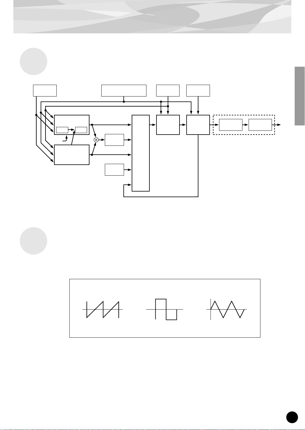
As the PLG150-AN Tone Generator Block Diagram (page 7) illustrates, the VCO module generates
the basic signal, then passes it along the signal path to the MIXER and VCF modules, processing
the signal in a variety of ways before passing it on to the VCA module, which controls the volume of
the signal — before passing it along to be processed (by Distortion and 3-BandEQ) along with the
other Parts of the tone generator. Along the way, various real-time and other controllers can be
applied to each module in a variety of ways , providing enormous sound-shaping and sound-creating
possibilities.
Some of the parameters mentioned in the following explanations cannot be accessed from the “mother” device;
however, they can be controlled with the special AN Easy Editor and AN Expert Editor plug-in software modules
(used in XGworks or XGworks lite). Even without the use of the plug-in software, the original AN voices of the
PLG150-AN provide enormous sonic complexity and flexibility, especially with the use of the Part parameters and
the AN Assignable Controllers on the “mother” device.
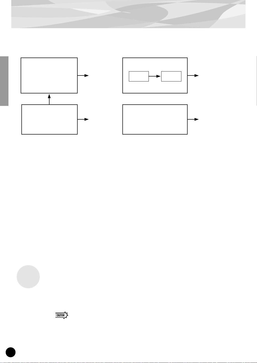
Oscillators, Filters And Amplifiers
What does it take to make a sound? And how does the PLG150-AN generate sounds?
In the simplest of terms, there are three basic elements which make up a sound: pitch, or how low or high it
is; tone, or what its overall quality, or timbre is like; and amplitude, or how loud the volume level is.
Synthesizers rely on three key electronic components to generate sounds and electronically imitate the
soundwaves of familiar musical instruments, as well as create entirely unique sounds. In traditional analog
synthesis, the source sound pitch and waveform is generated by an oscillator; its tone is controlled by a filter; and its volume is determined by an amplifier. With the PLG150-AN, these three elements are termed
the VCO (voltage controlled oscillator), the VCF (voltage controlled filter), and the VCA (voltage controlled amplifier).
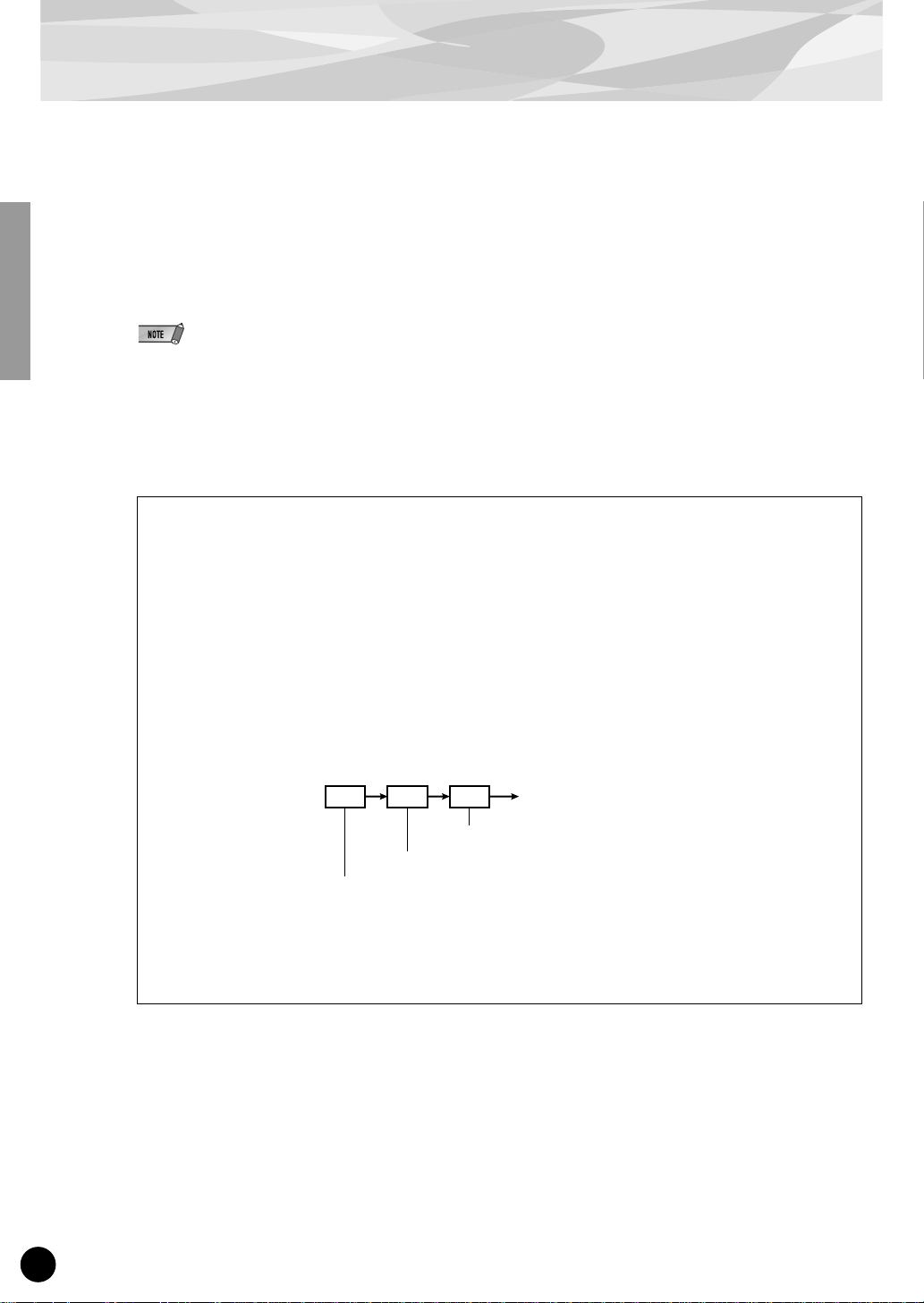
VCO VCF VCA OUT
The amplifier determines the volume
The filter controls the timbre
The oscillator creates the source pitch
(and also the basic timbre, depending on the waveform)
The “signal path” starts at the VCO, flows to the VCF, then flows to the VCA. The signal is “processed” at
each block, or “module” along the way to the final output.
6
Page 7
Analog Physical Modeling Synthesis and the PLG150-AN Tone Generator
PLG150-AN Tone Generator Block Diagram
VCO
PEG
VCO1
Oscillator Sync
Master
FM
VCO2
Slave
Oscillator
Sync
LFO1 & LFO2
Ring
Modulator
MIXER
Noise
FEG AEG
Feedback
VCA
Effects
Distortion
3-Band EQVCF
The VCO module is where the original sound waveform is generated. In general, the VCOs of analog
synthesizers feature the simple waveforms shown below.
Saw (Sawtooth) Pulse (Square) Triangle
Basic sawtooth waveform Basic pulse waveform Basic triangle waveform
In theory, these waveforms are very simple; in the real world, they’re not so simple. Because of the
characteristics of electronic circuits, all analog synthesizers introduce subtle imperfections into the
waveform. These imperfections result in slightly rounding off the edges of the wave, or adding noise,
and other artifacts — and they give each synthesizer its own special, unique sound.
Although a single oscillator is enough to generate the basic sawtooth, pulse (square) or other waves
required for different types of musical instrument sounds, the PLG150-AN’s VCO module provides
far greater flexibility. The PLG150-AN’s digital VCO creates mathematically exact waveforms.
7
Page 8

Analog Physical Modeling Synthesis and the PLG150-AN Tone Generator
However, the instrument also gives you a wide variety of tools (including Pulse Width Modulation
and Edge) for introducing analog-like “imperfections” to the waveforms and making them much more
complex and interesting.
The VCO of the PLG150-AN actually has two blocks: VCO 1 and VCO 2. With VCO 1, you can
select a variety of wav es, and it can be configured with one of three “sync modes” that syncs “master”
and “slave” oscillators within the VCO 1. Thus, when the sync is on, the VCO 1 is actually two oscillators in one, and additional waves are available.
The VCO 1 is alw ays fixed as the FM carrier, but the carrier can either be the master or slave oscillator
depending on the selected algorithm, when Sync mode is set to on. The FM modulator can be
selected from VCO2, the PEG, FEG, LFO1, LFO2 or others. The Pitch Envelope Generator (PEG)
lets you determine how the pitch of the VCO changes o v er time, and the LFO can be used to modulate
the VCO to create vibrato.
The PLG150-AN also has a second oscillator section: VCO 2. VCO 2 has many of the same waves
and controls as does VCO 1, but differs slightly in the waves that are available . For certain waves, it
also features special cross-modulation that generates complex harmonics by modulating the frequency of the oscillator. The VCO 2 can also be set (with the Sync parameter) to modulate the VCO
1.
■
Pulse Width and Pulse Width Modulation
In conventional analog synthesizers, pulse width (PW) is used to change the shape of a pulse waveform. This changes the harmonics or overtones (which determine the timbre or tone) of the sound.
Pulse width modulation (PWM) uses an LFO to periodically change the width, and hence, the harmonics.
The PLG150-AN lets you control not only the Pulse wave in this way, but also Saw and Mix (a combination of Saw and Pulse). In addition to using an LFO to modulate the Pulse Width, the PLG150AN lets you create a “fat” chorus-like effect, depending on the parameter settings.
Saw (Sawtooth)Pulse
When the Pulse
When Pulse
Width is small...
...the sound has
many harmonics.
Width is set to
"64" (50%)...
...the sound is that
of typical pulse
wave, with only
odd-numbered
harmonics.
When Pulse
Width is large...
...the sound has
many harmonics.
Basic sawtooth
waveform.
When Pulse Width
is set to a value
under “64”.
8
Page 9
Analog Physical Modeling Synthesis and the PLG150-AN Tone Generator
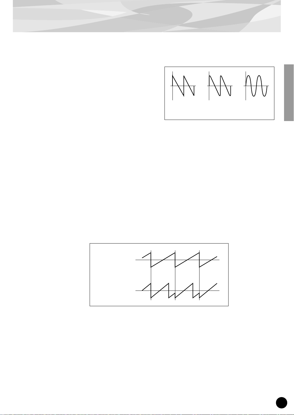
■
Edge
This useful parameter lets you make fine, subtle
changes to the waveform. Higher Edge v alues produce a sharper waveform, resulting in a harder,
harsher sound with many harmonics. Reducing the
value makes the waveform rounder, producing a
softer, warmer sound. (At the minimum v alue, this
actually results in a sine wave.)
■
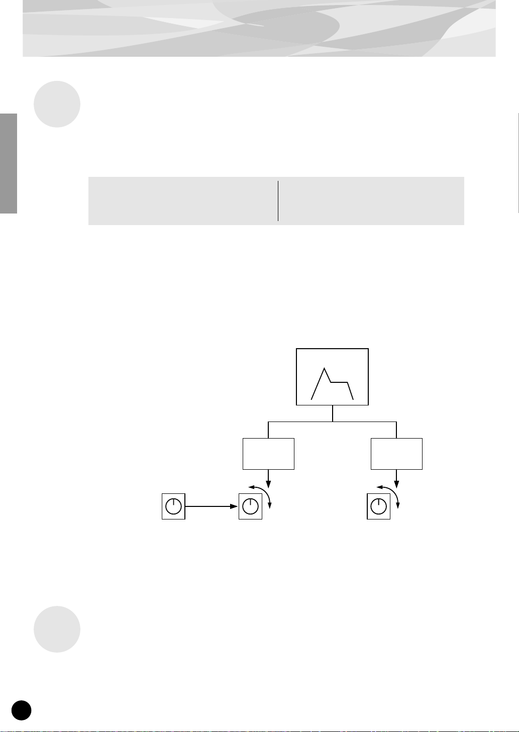
Oscillator Sync
Oscillator Sync is another common function in analog synthesis that synchronizes one oscillator’s
waveform with that of another oscillator.
In the illustration below, the waveform of oscillator 1 is constantly reset so that it starts its wave cycle
at the same phase point (the first position of the wave cycle) as oscillator 2. As a result, the waveform
of oscillator 1 becomes more complex than normal, adding harmonics to the sound. (In the illustration below, the sound of oscillator 1 becomes brighter than what it would be originally.)
Sharp-edged
waveform
Slightly rounded
edges
Sine wave
Here, oscillator 1 is referred to as the “slave” oscillator, while oscillator 2 is called the “master.”
Changing the pitch of the master oscillator changes the pitch of the overall sound. On the other hand,
changing the pitch of the slave oscillator changes the timbre or tone of the overall sound by altering
the amount of harmonics.
Oscillator 2 (master)
Oscillator 1 (slave)
Just as with conventional analog synthesizers, the PLG150-AN allows you to synchronize the oscillators of VCO 1 and VCO 2. What’s more, it allows you to use Oscillator Sync with only VCO 1, since
VCO 1 actually has two oscillators by itself.
9
Page 10
Analog Physical Modeling Synthesis and the PLG150-AN Tone Generator
VCO1
Slave oscillator.
Determines the timbre
or tone.
Oscillator Sync
VCO2
Master oscillator.
(This determines the pitch.)
Using Oscillator Sync to lock VCO 1 to VCO2
This method is the same as on conventional analog
synthesizers. The sound quality can be changed by
giving VCO 1 and VCO 2 different pitches.
■
FM
Adds harmonics
to the sound,
due to Oscillator
Sync.
Output of the
basic sound.
FM uses the wave of one oscillator (called the “modulator”) to periodically change the pitch or frequency of another oscillator (called the “carrier”).
VCO1
Oscillator Sync
Master
oscillator
Determines
the pitch.
VCO2
Using Oscillator Sync within VCO 1
This method is unique to the PLG150-AN. Since
VCO 1 and VCO 2 are independent, you can still use
Oscillator Sync to get more harmonics, yet layer VCO
1 and VCO 2 to produce sound of even greater
complexity and richness.
Slave
oscillator
Determines
the timbre or tone.
Adds harmonics to
the sound, due to
Oscillator Sync.
A different sound can
be layered, completely
independent of the
oscillator sync output
of VCO 1.
The FM generated sound is output by the carrier, and the type and amount of harmonics that are added
to the sound differs depending on the ratio of the modulator and carrier frequencies.
On the PLG150-AN, the following can be used as the modulator: VCO 2, LFO, and each EG. The
carrier is fixed to VCO 1.
Noise, Ring Modulator and Feedback
In addition to the VCO 1 and VCO 2 oscillators, the PLG150-AN includes a Noise oscillator, plus
Ring Modulator and Feedback controls. The levels of these five sound sources can be freely mixed,
giving you a wide range of sonic possibilities and comprehensive sound shaping control.
Avoid making drastic changes to Feedback, or setting the Feedback level to values at or near
the maximum. Doing so could damage your speakers (and your ears!). If you hear any strange
or unusual vibrations in your speakers as you are adjusting the Feedback level, immediately
turn Feedback down.
10
Page 11
VCF
Analog Physical Modeling Synthesis and the PLG150-AN Tone Generator
Once the VCO 1, VCO 2, Ring Modulator, Noise and Feedback signals are mixed in the MIXER
module, they can then be filtered by the VCF module. The VCF includes a comprehensive set of filters, including Low Pass Filter (LPF), High Pass Filter (HPF), Band P ass Filter (BPF) and Band Eliminate Filter (BEF). You can determine the Cutoff frequency of the VCF, as well as amount of
Resonance, or emphasis around the frequency cutoff point. Resonance and Cutoff actually work
interdependently with each other, and their overall effect depends also on the voice selected. On the
PLG150-AN, you can adjust the Cutoff frequency over an exceptionally wide range. Also, high values for Resonance create a relatively warm analog-like quality.
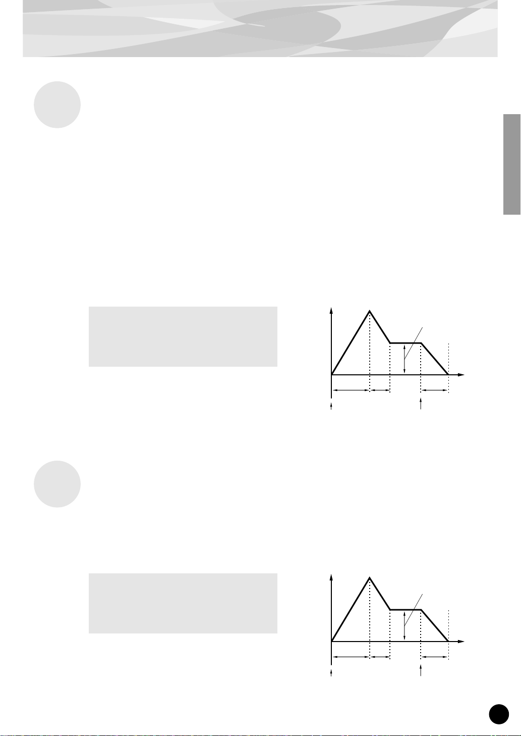
The Filter Envelope Generator (FEG) lets you determine how the timbre of the signal changes over
time, and the LFO1 or LFO2 can be used to modulate the VCF to create wah.
VCA
The FEG features four parameters:
Attack Time
Decay Time
Sustain Level
Release Time
Level
Sustain
Time
Attack ReleaseDecay
Key on Key off
The VCA module is where the overall output level of the signal is determined. The Amplitude Envelope Generator (AEG) lets you determine how the volume of the signal changes over time, and the
LFO1 or LFO2 can be used to modulate the VCA to create tremolo.
The AEG features four parameters:
Attack Time
Decay Time
Sustain Level
Release Time
Level
Sustain
Attack ReleaseDecay
Key on Key off
Time
11
Page 12
Analog Physical Modeling Synthesis and the PLG150-AN Tone Generator
LFO 1, 2 and PEG, FEG
The LFO 1 and LFO 2 sections provide a sophisticated set of modulation possibilities, allowing you
to modulate the VCO 1, VCO 2, VCA, and VCF sections in various ways and degrees.
The LFO can be used to control:
Pmod (pitch of the oscillator) PWM (Pulse Width Modulation)
Fmod (Cutoff frequency of the filter) Sync Pitch (pitch of the slave oscillator)
Amod (depth of the amplifier, or volume) FM Depth
This gives you enormous flexibility in controlling and shaping the sound.
The PEG (Pitch EG) section lets you control the pitch of the VCO 1 and/or VCO 2 over time, with a
conventional envelope generator. The FEG (Filter EG) gives you similar control over how the filter
affects the sound over time. On the PLG150-AN, the PEG and FEG give you additional modulation
control sources, providing the comprehensive and flexible control as found on vintage analog synthesizers — yet without the expense of additional modules and the complexity of dozens of patch cords.
Effects
Example
Oscillator
Pitch of the master
oscillator (determines the
pitch of the overall sound).
Sync
Pitch of the slave
oscillator (determines
the timbre or tone
of the overall sound).
Changing the
harmonics
over time.
FEG
Filter cutoff frequency
Opening and
closing the filter
over time.
12
The PLG150-AN also features an Effects section that includes Distortion and 3-Band EQ. These
effects give you further sonic control over the AN voice, letting you apply and adjust distortion, and
make detailed equalization settings.
Page 13

Memory Buffer Structure
● AN-XG Bank Voice 236 voices
MSB=84 (AN-XG/A)
LSB=0, 64 — 81, 96 — 107
PrgNo.=39 — 128 (origin : 1)
MSB=100 (AN-XG/B)
LSB=0, 64 — 76
PrgNo.=39 — 120 (origin : 1)
Voice
● Custom Bank Voice
Preset1 128 voices
MSB=36
LSB=0
PrgNo.=1 — 128 (origin : 1)
Preset2 128 voices
MSB=36
LSB=1
PrgNo.=1 — 128 (origin : 1)
User 128 voices
MSB=36
LSB=2
PrgNo.=1 — 128 (origin : 1)
* When the power is turned off and on again, the
contents of the User memory are replaced by voices
from the Preset 1 and 2 banks. To save your edits to a
User voice, use the AN Expert Editor software.
Voice
Voice
Voice
Voice Parameter
Tone Generator Parameter
VCO1, VCO2, SYNC, FM
MIXER, LFO1, LFO2
PEG, VCF (FEG), VCA (AEG),
DISTORTION, 3-Band EQ
Free EG
Free EG Parameter
Free EG Data
Pattern Generator
Arpeggio Parameter
Step SEQ Parameter
Step SEQ Pattern Data
Part Parameter
XG Part Parameter
AN Native Part Parameter
User Step SEQ Pattern
Step SEQ Parameter
Step SEQ Pattern Data
System Parameter
AN Native System Parameter
128
patterns
13
Page 14

Specifications
TONE GENERATOR/MODULES :
Analog Physical Modeling, 2VCO(OSCILLATOR & FM), Ring Modulator,
Noise, VCF(FEG), VCA(AEG), PEG, 2LFO, Arpeggio/Step Sequencer
Generator, 4 Track FreeEG
POLYPHONY :
NUMBER OF VOICES :
INTERFACE :
EFFECTOR :
DIMENSIONS (W x H x D) :
WEIGHT :
POWER REQUIREMENTS :
INCLUDED ITEMS :
5 notes maximum (latest note priority; polyphony is expandable *1)
*1 Depending on the particular “mother” device, up to eight additional
boards can be installed, for a total of 40-note polyphony. On the CS6x,
for example, two boards can be installed for a maximum of 10 notes; on
the MU128, three boards can be installed for a maximum of 15 notes.
236 XG voices (AN-XG/A, AN-XG/B)
256 Preset voices
128 User voices
XG Plug-in connector
Guitar Amp.Simulator (Distortion)
3-Band EQ
XG Part EQ
138.5 x 89.0 x 8.5mm
65g
320mA
Owner’s Manual, Floppy disk (3)
* Specifications subject to change without notice.
About the Included Floppy Disks
The three included floppy disks contain editing software for the PLG150-AN as well as demonstration songs and Voice/Performance data for the “mother” device.
To use the editing software and transf er the song/Voice/Performance data to your particular “mother”
device, you should have a computer (running Windows 95/98) with a MIDI interface, with the MIDI
OUT on the interface connected to the MIDI IN of the “mother” device. You should also have
XGworks (v3.0 or higher) or XGworks lite installed to your computer; this is necessary to use the
editing software (page 17). For playing back the demonstration songs and transferring the Voice/
Performance data, you can use any compatible sequence software (such as XGworks/XGworks lite)
or hardware sequencer capable of sending bulk data. Insert Disk #1 into the computer and start the
installation.
The following software is included on the disks:
14
Page 15

About the Included Floppy Disks
■
AN Easy Editor (page 17)
■
AN Expert Editor (page 17)
■
Demonstration Songs
(1) “AN Solo” (for Modular Synthesis Plug-in System devices:M_Solo.MID)
(for XG Plug-in System devices:X_Solo.MID)
By: Katsunori Ujiie (Idecs, Inc.)
For: Modular Synthesis Plug-in System devices (CS6x, etc.) and XG Plug-in System devices
(MU128, etc.)
To play this song with a Modular Synthesis Plug-in System device (such as the CS6x, etc.), first call up
the Voice mode (press the VOICE button), then press PLG1 or PLG2 (depending on which slot the
PLG150-AN board has been installed to), and select a voice.
(2) “R&B” (R&B.MID)
By: Takashi Morio
For: XG Plug-in System devices (MU128, etc.)
(3) “Old Tek” (Old_T ek.MID)
By: Takashi Morio
For: XG Plug-in System devices (MU128, etc.)
(4) “Progressive Rock” (Progrock.MID)
By: Katsumi Nagae (Idecs, Inc.)
For: XG Plug-in System devices (MU128, etc.)
(5) “Trance” (Trance.MID)
By: Katsumi Nagae (Idecs, Inc.)
For: MU128/MU100/MU100R
■
Plug-in Voice Data for the CS6x/CS6R/S80
(Modular Synthesis Plug-in System)
This is Plug-in voice data, featuring a total of 64 voices that were created using the PLG150-AN Preset voices. When the PLG150-AN is installed to PLG1, select the file “PLG_vce1.MID”; when the
board is installed to PLG2, select the file “PLG_vce2.MID.”
For a complete list of these voices, refer to the Plug-in Voice List (page 45) in the Owner’s Manual.
■
Performance Data for the MU128/MU100/MU100R (XG Plug-in System)
This is Performance data, featuring a total of 64 Performances that were created using the PLG150AN Preset voices (“AN_Perf.MID”).
For a complete list of these P erf ormances, refer to the Performance List (page 46) in the Owner’ s Manual.
15
Page 16

Installing the PLG150-AN
For detailed instructions on installing the PLG150-AN, refer to the owner’s manual of the Plug-incompatible “mother” device (e.g., CS6x, MU128, etc.).
Included Items
The following items have been included in the package of your new PLG150-AN. Please make sure
that you have them all before starting to setup and use the instrument. If an item is missing, contact
the store or dealer from which you purchased the PLG150-AN.
• PLG150-AN board
• PLG150-AN Owner’s Manual (this book)
• Three floppy disks
Required and Recommended Items
In addition to the included items listed above, you should also have the following:
Synthesizer/Tone Generator/Sound Card Compatible with the Modular Synthesis or XG Plug-in Systems
16
In order to use the PLG150-AN, you’ll need a synthesizer, tone generator or sound card compatible
with the Modular Synthesis Plug-in System or the XG Plug-in System. Compatible instruments
include the CS6x, MU128, and the SW1000XG. The synthesizer/tone generator/sound card should
also have an available slot or space for installing the PLG150-AN.
Page 17

Required and Recommended Items
XGworks or XGworks lite Music Sequencing Software
These software sequencers provide convenient tools for taking full advantage of the PLG150-AN, letting you create song data that automatically selects and plays back the AN voices. They also include
the powerful AN Easy Editor and AN Expert Editor (see below) for editing and controlling the AN
voices. XGworks lite is contained on a CD-ROM included with the CS6x, MU128, etc., and
XGworks is contained on a CD-ROM included with the SW1000XG.
AN Easy Editor
The AN Easy Editor is a special plug-in software module for XGw orks and XGw orks lite. It pro vides
convenient easy-to-use control over the most important PLG150-AN settings and parameters. It also
provides exceptionally intuitive editing, with a virtual “front panel” display that lets you change the
settings with knobs and buttons.
Using the AN Easy Editor is just like using the Part editing controls on your tone generator — it indirectly and temporarily changes the AN voices without making changes to the original voice. The
changed parameters can either be inserted into a song to automate sound changes, or can be saved as
an AN parameter file for future recall. Continuous real-time parameter changes can be recorded to a
song as well. The AN Easy Editor software is contained on the included floppy disks.
AN Expert Editor
As with AN Easy Editor above, the AN Expert Editor is special software for use with XGworks and
XGworks lite. It allows you to directly edit all of the AN voice settings and parameters from your
computer. It also pro vides exceptionally intuitive editing, with a virtual “front panel” display that lets
you change the settings with knobs, buttons and other controls.
More comprehensive than the AN Easy Editor above, the AN Expert Editor gives you convenient
access to all of the PLG150-AN’s parameters, controls and functions. The changed parameters can
either be inserted into a song to automate sound changes, or can be saved as an AN Expert Data file
for future recall. Continuous real-time parameter changes can be recorded to a song as well. It also
lets you save your edits directly as a User voice for future recall.
The AN Expert Editor software is contained on the included floppy disks.
17
Page 18

Installing and Starting the Plug-in Editor Software
(Windows 95/98)
Installing the Software
Double-click the “Setup.exe” file in the “plg-an” folder on the floppy disk to start the installation.
Click “Next” or “Yes” and follow the subsequent instructions on the screen to complete the installation.
Starting the AN Easy Editor
Start XGworks (or XGworks lite).
1
Click the “Plug-in” menu and select “AN
2
Easy Editor.”
Alternately, press Alt + P, then A, and ENTER. The
“Select AN Part” dialog box appears.
18
Set the desired Part number and click “OK.”
3
The AN Easy Editor window appears.
If the PLG150-AN has been
properly installed and all computer/MIDI connections have
been properly made, operating
the AN Easy Editor should
directly affect the PLG150-AN.
For details on using the AN Easy
Editor, refer to the on-line help
file that is included with the software.
When using a Modular Synthesis Plug-in System “mother” device, the Part assignment depends on
which mode is used — Voice or Performance — and also on whether the PLG150-AN board is
installed/assigned to PLG1 or PLG2, as described below.
When using the Voice mode:
Depending on which slot the PLG150-AN board has been installed to, press PLG1 or PLG2, then
set the Part to “1” (no matter what the PLG1 or PLG2 assignment is).
When using the Performance (Multi) mode:
If the PLG150-AN board is assigned to PLG1, set the Part to “16.”
If the PLG150-AN board is assigned to PLG2, set the Part to “15.”
Page 19

Installing and Starting the Plug-in Editor Software (Windows 95/98)
Starting the AN Expert Editor
1 Start XGworks (or XGworks lite).
2 Click the “Plug-in” menu and select “AN
Expert Editor.”
Alternately, press Alt + P, then A (twice), and ENTER.
The “Select AN Part” dialog box appears.
3 Set the desired Part number and click “OK.”
The AN Expert Editor window appears.
If the PLG150-AN has been properly installed and all computer/MIDI connections have been
properly made, operating the AN Expert Editor should directly affect the PLG150-AN. For
details on using the AN Expert Editor, refer to the on-line help file that is included with the software.
● To use the AN Expert Editor, your copy of XGworks must be version 1.05 or later.
You can download the proper update of XGworks or XGworks lite from the Yamaha website
(http://www.yamaha.co.uk).
● When using a Modular Synthesis Plug-in System “mother” device, the Part assignment depends on
which mode is used — Voice or Performance — and also on whether the PLG150-AN board is
installed/assigned to PLG1 or PLG2, as described below.
When using the Voice mode:
Depending on which slot the PLG150-AN board has been installed to, press PLG1 or PLG2,
then set the Part to “1” (no matter what the PLG1 or PLG2 assignment is).
When using the Performance (Multi) mode:
If the PLG150-AN board is assigned to PLG1, set the Part to “16.”
If the PLG150-AN board is assigned to PLG2, set the Part to “15.”
19
Page 20

Selecting AN Voices
(Modular Synthesis Plug-in System)
When the PLG150-AN is installed to a CS6x Control Synthesizer, the AN voices can be selected in
the same way as the internal voices of the synthesizer.
The example displays used in the following explanations are all taken from the CS6x.
Enabling and Selecting AN Voices
1 Press the VOICE button.
2 Press the appropriate PLG button (PLG1 or PLG2, depending on which
slot the PLG150-AN board has been installed to), then press the appropriate BANK button and PROGRAM button to select the desired Plug-in
voice.
VCE Play) PLG1:001(A01)[--:Killer ]
EQLow-G EQMid-G EQHi-G ------- -------
To select a different bank, simultaneously hold down the appropriate PLG button and turn knob C (or
press the DEC/INC buttons) to select the desired bank.
The bank is expressed in two numbers: MSB and LSB.
VCE Play) PLG1:001(A01)[--:Killer ]
BANK= 036/000
If a selected bank is not available, the bank letter indication in the display (A - H) will not change.
For a list of the available banks and their MSB/LSB values, refer to the “AN-XG Voice Map” at
the back of this manual (pages 43 — 44).
20
Page 21

Editing the AN Native Part Parameters
(Modular Synthesis Plug-in System)
● Keep in mind that the parameter values and settings below represent offsets of the actual voice settings. This
means that adjustments made to the parameters may not make much change in the actual sound, depending
on the original settings of the voice. For parameter values, a setting of “0” results in no change, while positive
and negative values increase and decrease the value respectively.
● The following explanations show how to edit the AN native part parameters when creating PLG voices, using
the CS6x Control Synthesizer as an example. For information on storing the PLG voices with your particular
Modular Synthesis Plug-in System compatible instrument, refer to the owner’s manual of that instrument.
1 Select the desired AN voice, as described in “Selecting AN Voices” on
page 20.
2 Press the EDIT button.
The EDIT menu display appears.
GEN Name) Pf-Sq a-Z 0-? Cursor
Common [--:Killer ]
3 Turn knob A clockwise until “Elem” is shown at the bottom left of the dis-
play.
PLG Assign) Bank Number
Elem 036/000 1[Killer ]
4 Turn the PAGE knob clockwise until “PLG150-AN” is shown at the bottom
left of the display.
Keep turning the knob to select the different AN Part parameters, indicated just above knob C and
knob 2.
NTV Param) Unison Sw Arp/SEQ Sw
PLG150-AN Vce Off
5 Use knobs C and 2 to select the desired parameter and change the value.
Once one of the parameters is selected (the arrow cursor appears next to the value), you can also
adjust the value with the DATA knob or the DEC/INC buttons.
● In order to store User voices on a Modular Synthesis Plug-in System compatible instrument that
have been edited/created with the computer-based AN Expert Editor (or with the compatible instrument itself), you’ll need to use an external memory device, such as a memory card. For details on
storing voices, refer to the owner’s manual of your Modular Synthesis Plug-in System compatible
instrument.
● The actual parameter names may differ, depending on whether the instrument you are using is XG
Plug-in System compatible or Modular Synthesis Plug-in System compatible. For details, refer to
the Parameter List (XG / Modular Synthesis Plug-in System) on page 50.
You can use the Mono/Poly Mode and Portamento Switch parameters in tandem to create a smoother
note-to-note sound when playing legato passages. To do this, set Mono/Poly Mode to “Mono” and Portamento Switch to “On.” When set in this w ay, sucessively played notes do not retrigger the PEG, FEG
or AEG, resulting in a smoother, more consistent sound.
21
Page 22

Selecting/Editing the AN System Parameters
(Modular Synthesis Plug-in System)
The example displays used in the following explanations are all taken from the CS6x.
1 Press the UTILITY button.
The Utility Mode display appears.
MSTR TG) Vol NtShift Tune
Sys 127 + 0 + 0.0c
2 Turn the PAGE knob clockwise until “PLG150-AN” is shown at the bottom
left of the display.
Keep turning the knob to select the different AN System parameters, indicated just above knob C
and knob 2.
PLG1 MIDI) Mrph CtrlNo Mrph Pgm No
PLG150-AN 0 0
3 Use knobs C and 2 to select the desired AN System parameter and change
the value.
Once one of the parameters is selected (the arrow cursor appears next to the value), you can also
adjust the value with the DATA knob or the DEC/INC buttons.
22
Page 23

Selecting AN Voices (XG Plug-in System)
The PLG150-AN voices can be selected just like the v oices of the XG tone gener ator. Keep in mind,
though, that they can only be selected when the Sound Module Mode is set to XG or Performance.
Also, the Part Assign parameter in the Utility mode (see below) must be set to the desired Part.
The example displays used in the following explanations are all taken from the MU128.
Enabling and Selecting AN Voices
1 Set the Sound Module Mode to “XG” or “PFM” (Performance).
Press the MODE button and use the SELECT </> buttons.
The Performance mode is not available on the SW1000XG.
2 Set the Part Assign parameter to the desired Part number.
To do this:
1) Press the UTIL button.
2) Select the “PLUGIN” menu (with the SELECT
3) Select the “PLG150-AN” menu if necessary (with the SELECT
ENTER.
4) Select the Part Assign parameter (with the SELECT
tons or dial to change the Part number.
> button) and press ENTER.
</> buttons), and press
< button), and use the VALUE -/+ but-
The Part Assign range for the XG mode is 1 - 16 and “off”; for the Performance mode, it is 1 - 4 and
“off.”
Press the EXIT button to return to the Play mode.
This operation can also be quickly and conveniently done from the AN Easy Editor or AN Expert
Editor (in XGworks).
3 Enable the PLG150-AN board for the desired Part.
First, make sure that the appropriate Part is selected (using the PART -/+ buttons), then press the
SELECT button. The icon of the selected board appears in the display and the corresponding
LED at the bottom of the panel (PLG-1, -2, or -3) flashes briefly.
23
Page 24

Selecting AN Voices (XG Plug-in System)
4 Select the desired bank number.
Move the cursor to the Bank Number parameter with the SELECT </> buttons and use the
VALUE -/+ buttons to select the desired bank.
5 Select the desired voice number.
Move the cursor to the Voice (Program) Number parameter with the SELECT </> buttons and
use the VALUE -/+ buttons to select the desired voice.
Voices (and Voice banks) can also be selected by using the Voice Category buttons.
Alternately, you can select v oices from a connected MIDI ke yboard, or from sequencing software
(such as XGworks) on a connected computer.
Bank Number parameter
For a list of available voices and their bank/voice numbers, see page 43.
24
Page 25

Editing the AN Native Part Parameters
(XG Plug-in System)
Any of the AN voices can be freely edited from the front panel with the AN Par t parameters. These
same parameters can also be edited from a computer using the AN Easy Editor software (in
XGworks).
Keep in mind that changing the Par t parameters does not permanently affect the original voice settings. The edits that you make here temporarily change the settings of the currently selected voice.
When you select a different voice for the Part, the settings are applied to the newly selected voice.
● The Part parameter settings cannot be saved in Multi Play mode. If you wish to save your Part parameter
edits, do it from the Perf ormance mode or the AN Easy Editor. If you wish to sav e y our edits to a v oice , use the
AN Expert Editor software to edit the parameters of a voice, then save it as a User voice.
● The example displays used in the following explanations are all taken from the MU128.
1 Select the Part having the AN voice, then select the desired voice.
Select the appropriate Part with the PART -/+ buttons, then, with the cursor at the Voice Number
parameter, select the desired voice.
2 Press the EDIT button to enter the Edit mode.
3 Select the “PLUGIN” menu.
Use the SELECT > button, then press the ENTER button. The PLG150-AN Edit menu appears.
4 Select the desired parameter.
Use the [SELECT </>] buttons.
5 Adjust the value or change the setting for the selected parameter.
Use the [VALUE +/-] buttons.
25
Page 26

Editing the AN Native Part Parameters (XG Plug-in System)
6 Return to the main Play display.
Press the [EXIT] button several times, or press the [PLAY] button once.
● When an AN voice is selected from one of the custom banks (Preset 1, Preset 2, or User), the AN
voice’s settings for the following parameters take precedence over the corresponding XG Part settings.
Mono/Poly Mode
Pitch Bend Control
Portamento Switch
Portamento Time
In other words, the settings of these XG Part parameters (on an MU128, etc.) are replaced by those
of the selected AN voice. Naturally, once the voice is selected, the Part parameter values can then
be changed from the panel of the XG-compatible “mother” device (MU128, etc.), or by sending
appropriate MIDI messages.
● When an AN voice is properly assigned to a Part on an XG-compatible “mother” device (MU128,
etc.), the AN voice can be changed by editing the XG Part parameters from the panel. However, for
the following XG Par t parameters, changing the value has no effect on the sound (even though the
value changes in the display).
PEG ReleTime (Pitch EG Release Time)
PEG ReleLvl (Pitch EG Release Level)
26
Page 27

Selecting/Editing the AN System Parameters
(XG Plug-in System)
The parameters that apply to the entire system of the PLG150-AN are included in the Utility mode
menu of the XG tone generator.
The example displays used in the following explanations are all taken from the MU128.
1 Press the [UTIL] button.
The Utility mode menu appears.
2 Select the “PLUGIN” menu.
Use the [SELECT >] button to highlight “PLUGIN,” then press the [ENTER] button.
3 Select the PLG150-AN board.
If the PLG150-AN board is the only one installed, “PLG150-AN” is already displayed and can be
selected by pressing the [ENTER] button. If additional boards have been installed to the tone
generator, you may need to select “PLG150-AN.” To do this, first use the [SELECT </>] buttons, then press [ENTER].
The System parameter menu for the PLG150-AN appears.
4 Select the desired parameter.
Use the [SELECT </>] buttons.
5 Adjust the value or change the setting for the selected parameter.
Use the [VALUE +/-] buttons.
6 Return to the main Play display.
Press the [EXIT] button several times, or press the [PLAY] button once.
27
Page 28

Parameters
AN Native Part Parameters
Keep in mind that the parameter values and settings represent of fsets of the actual v oice settings. This
means that the actual sound that results from the settings made here depends on the original settings
of the voice.
Also keep in mind that these are “Part” parameters and as such, are temporary; they simply alter or
offset the settings of the currently selected voice. The original voice settings are permanently maintained in memory.
For parameter values, a setting of “0” results in no change, while positiv e and ne gati v e v alues increase
and decrease the value respectively.
Let’s look at a specific example. If the original Mix VCO1 Level parameter of the selected voice is
set to 100, and you set the Mix VCO1 Level (below) to “-25,” the actual Mix VCO1 Level will
become “75.” If you set it to “+10,” the value will become “110.” Naturally, this also means that the
parameter value cannot be increased or decreased beyond its maximum or minimum values. In our
example, Mix VCO1 Level values higher than “+27” have no effect on the sound, since the actual
range is 0 — 127.
● Depending on the selected voice and the particular parameter being edited, the sound or actual
parameter value of certain voices may change v ery little or not at all, ev en when the parameter v alue
is changed drastically.
● For Modular Synthesis Plug-in System compatible devices, the voices you edit/create can be stored
to the device as PLG voices. For details on storing voices, ref er to the owner’s manual of your Modular Synthesis Plug-in System compatible instrument.
■ Unison Sw (Unison Switch)
Settings: vce (voice), off, on
This determines whether the Unison mode is on or off. Setting this to on is an instant w ay to get a “fat”
analog-like lead sound. When Unison is on, the selected voice is layered with slightly detuned copies
of itself, and set to play monophonically (one note at a time). When this is set to “vce” (voice), the
default Unison Switch setting for the v oice is used. In other words, the Unison mode will turn on and off
automatically, depending on the selected voice.
● This setting overrides the Mono/Poly Mode par ameter setting (of the Modular Synthesis Plug-in Sys-
tem PLG voice or the XG Part). Even if the PLG voice or the XG Part is set to “poly,” the voice will
only play monophonically (with up to five v oices sounding together) when Unison Switch is set to on.
● All voices in the AN-XG voice bank have a default Unison Switch setting of “off.” This means that
setting this parameter to “vce” (voice) is the same as setting it to “off.”
28
Page 29

Parameters
■ Arp/SEQ Sw (Arpeggio/Step Sequencer Switch)
Settings: vce (voice), off, on
This determines whether the Arpeggio or Step Sequencer is on or off. When this is set to on, the
Arpeggio or Step Sequencer function can be used. When this is set to “vce” (voice), the def ault Arpeggio/Step Sequencer Switch setting for the voice is used. In other words, the Arpeggio/Step Sequencer
will turn on and off automatically, depending on the selected voice.
Refer to the Preset1/2 Bank Voice List (pages 38 — 41) for details on whether the Arpeggio or Step
Sequencer is set to on or not for the selected voice.
■ Tempo
Settings: vce (voice), midi (midi clock), 40 - 240 bpm
This determines the tempo for the PLG150-AN’s internal clock in beats per minute (bpm), o ver a range
of 40 - 240 bpm. The Tempo setting controls the playback of both the Arpeggio and Step Sequencer.
When Tempo is set to “midi,” the clock of the PLG150-AN can be controlled by the clock of an external
MIDI device such as a music sequencer, connected to the MIDI IN terminal. When this is set to “vce”
(voice), the default Tempo setting for the voice is used.
When the Free EG Length parameter is set to one of the “bar,” the Free EG sequence will be synchronized with the Tempo set here.
■ LFO2 Speed
Range: -64 — +63
This determines the speed of the LFO2 modulation. The higher the value, the greater the modulation
speed.
The LFO1 speed is controlled by Vibr ato Rate in the Modular Synthesis Plug-in System PLG voice and
the XG Part parameters. (Refer to the manual of your specific synthesizer/tone generator.)
■ Sync Pitch (Oscillator Sync Pitch)
Range: -64 — +63
This determines the pitch of the slave oscillator in semitones, available only when Sync is set to on.
This lets you create a difference in pitch between master and slave oscillators and control the resulting
harmonic interval.
Higher values increase the interval, and lower values result in a softer sound.
● To acheive a discernible result, make sure that the VCO1 Level (page 31) is set to an appropriately
high value.
● For voices whose Oscillator Sync Mode parameter is set to off, this parameter cannot be changed
****” appears in the display).
(“
29
Page 30

Parameters
■ FM Depth
Range: -64 — +63
This determines the amount of modulation created by the FM function. Higher values result in greater
modulation depth.
■ VCO Detune
Range: -64 — +63
This determines the amount of pitch difference between VCO1 and VCO2.
■ VCO1 Edge
Range: -64 — +63
This determines the sharpness or smoothness of
the edge of the VCO1 waveform. Higher (positive)
values produce a sharper wave, resulting in a
harsher sound. Lower (negative) values produce a
rounder wave, resulting in a softer sound. A value
of “-64” results in a sine wave.
● This parameter differs from that in FM Synthesis (such as used by DX-series synthesizers). Too
deep of a setting will change the pitch of the voice.
● Depending on the selected voice, this parameter may not be changeable (“****” appears in the
display).
Sharp-edged
waveform
Slightly rounded
edges
Sine wave
30
■ VCO1 PW (Pulse Width)
Range: -64 — 0 — +63
This determines the width of the VCO1 pulse wave. Higher (positive) values produce more harmonics,
resulting in a fatter sound. In general, pulse width is used to control the pulse wave; however, the
PLG150-AN can use PW with other waves as well, for a wider possible variety of sounds than usual.
When Pulse
Width is small...
...the sound has
many harmonics.
When the Pulse
Width is set to "64" (50%)...
...the sound is that of typical
pulse wave, with only
odd-numbered harmonics.
When Pulse
Width is large...
...the sound has
many harmonics.
Page 31

Parameters
■ VCO1 PWMDp (Pulse Width Modulation Depth)
Range: -64 — +63
This determines the amount of depth of the pulse width modulation of the VCO1, based on the PWM
Source parameter. Higher (positive) values produce a deeper modulation.
For most of the voices, the PWM Source is set to LFO2, but for some voices this is set to LFO1 or
another setting (depending on the selected voice).
■ VCO2 Edge
■ VCO2 PW (Pulse Width)
■ VCO2 PWMDp (Pulse Width Modulation Depth)
These parameters are the same as those of VCO1, described on pages 30 — 31.
■ Mix VCO1 (Mix VCO1 Level)
Range: -64 — +63
This determines the balance of the VCO1 level in relation to the VCO2, Ring Modulator, and Noise levels. Higher values result in a higher VCO1 level. Set this to "-64" when not using VCO 1.
■ Mix VCO2 (Mix VCO2 Level)
Range: -64 — +63
This determines the balance of the VCO2 level in relation to the VCO1, Ring Modulator, and Noise levels. Higher values result in a higher VCO2 level. Set this to "-64" when not using VCO 2.
■ Mix RingMd (Mix Ring Modulator Level)
Range: -64 — +63
This determines the balance of the Ring Modulator level in relation to the VCO1, VCO2, Noise, and
VCA Feedback levels. The higher the value, the greater the Ring Modulator level. When not using the
Ring Modulator, set this value to “-64.”
The Ring Modulator combines the VCO1 and VCO2 signals. It is particularly effective for producing
dissonant interval sounds with a clangorous, or metallic effect.
■ Mix Noise (Mix Noise Level)
Range: -64 — +63
This determines the balance of the Noise signal in relation to the VCO1, VCO2, Ring Modulator, and
VCA Feedback levels. The higher the value, the greater the Noise Level. When not using Noise, set
the level value to “-64.”
By mixing in Noise and using the AN Expert Editor to select an appropriate Filter Type (such as VCF,
HPF, etc.), you can create a wide variety of unique “special effect” sounds.
31
Page 32

Parameters
■ Mix FdBack (Mix Feedback Level)
Range: -64 — +63
This determines the level of feedbac k output from the VCA that is returned (or “fed back”) into the input
of the mixer, causing the signal to build up in amplitude according to the level you set. Higher values
increase the Feedback level, resulting in a fatter sound.
VCO Mixer HPF
Feedback
● Feedback should be applied slowly and with caution. Too much feedback can create extremely high
frequencies, potentially resulting in damage to your speakers.
● Too much feedback may drastically change the VCF characteristics.
VCF VCA OUT
■ VCF FmodDp (Filter Modulation Depth)
Range: -64 — +63
This determines the depth of the filter modulation of the VCF by the LFO1 or LFO2 (depending on the
voice selected). Filter Modulation adds a cyclical change to the filter cutoff frequency to create a wah
effect. Higher (positive) values widen the range of the cutoff frequency change.
■ FEG Depth (Filter EG Depth)
Range: -64 — +63
This determines the range of movement of the cutoff frequency. Higher (positive) values increase the
FEG Depth. This must be set to a proper level for the FEG parameters (Attack, Decay, Sustain, and
Release) to have an effect on the sound.
32
■ FEG Attack (Filter EG Attack Time)
Range: -64 — +63
This determines the attack time of the FEG, which is the time it takes for the signal to reach its maximum cutoff frequency level after a key is pressed (key on). Higher values produce a longer Attack
time.
■ FEG Decay (Filter EG Decay Time)
Range: -64 — +63
This determines the decay time of the FEG, which is the time it takes for the signal to reach its sustain
level from the maximum level while a key is held. Higher values produce a longer Decay time.
Page 33

Parameters
■ FEG Sustin (Filter EG Sustain Level)
Range: -64 — +63
This determines the level of sustain of the FEG, which is the fixed level of the cutoff frequency maintained as long as the key is held. Higher values increase the Sustain level.
■ FEG Releas (Filter EG Release Time)
Range: -64 — +63
This determines the release time of the FEG, which is the time it takes for the filter to reach a level of
“0” after a key is released (key off). Higher values increase the Release time.
■ VCA AmodDp (VCA Amplitude Modulation Depth)
Range: -64 — +63
This determines the depth of the amplitude modulation of the VCA by the LFO1 or LFO2 (depending
on the voice selected). Amplitude Modulation adds a cyclical change to the volume level to create a
tremolo effect. Higher (positive) values widen the range of the volume change.
■ AEG Attack (Amplitude EG Attack Time)
Range: -64 — +63
This determines the attack time of the AEG, which is the time it takes for the signal to reach its maximum volume level after a key is pressed (key on). Higher values produce a longer Attack time.
■ AEG Decay (Amplitude EG Decay Time)
Range: -64 — +63
This determines the decay time of the AEG, which is the time it takes for the signal to reach its sustain
level from the maximum level while a key is held. Higher values produce a longer Decay time.
■ AEG Sustin (Amplitude EG Sustain Level)
Range: -64 — +63
This determines the level of sustain of the AEG, which is the level at which the volume will be maintained as long as the key is held. Higher values increase the Sustain level.
■ AEG Releas (Amplitude EG Release Time)
Range: -64 — +63
This determines the release time of the AEG, which is the time it takes for the signal to reach a level of
“0” after a key is released (key off). Higher values increase the Release time.
33
Page 34

Parameters
■ Dist Drive (Distortion Drive)
Range: off, -63 — +63
This determines the amount of distortion “drive” for the guitar amplifier simulation effect block. The
higher the value, the greater the degree of distortion in the sound. When this is et to “off,” the guitar
amplifier simulation block is bypassed, regardless of the setting of the selected voice.
■ AC1CtrlPrm (AC1 Control Parameter Number)
Settings: off, P:1 — P:46
This determines which PLG150-AN parameter number is to be controlled by the Assignable Controller
(AC1). This allows you to continuously control any one of the PLG150-AN parameters in real time with
the desired MIDI controller (modulation wheel, breath controller, foot controller, etc.). For a list of the
parameters that can be controlled, see page 49. When this is set to “off,” AC1 control over the
PLG150-AN is disabled.
The actual controller that is used to affect the PLG150-AN is determined by the Assignable Controller
1 Control Change Number parameter (in the Modular Synthesis Plug-in System PLG voice or the XG
Part parameters). Refer to the relevant section in the manual of your specific synthesizer/tone gener ator.
■ AC1CtrlDp (AC1 Control Depth)
Range: -64 — drct (direct) — +63
This determines the depth over which the AC1 controller affects the specified PLG150-AN parameter
(set in AC1 Control Parameter Number above).
When the Control Depth is set to “drct,” the Direct Control function is enabled, allowing you to directly
edit the parameter assigned to the controller within its original range.
AN System Parameters
■ Part Assign
Settings: 01 — 16, off
This determines the Part to which the PLG150-AN voice is assigned. If a Part is not properly assigned
here, none of the PLG150-AN voices can be selected for the Part. (This applies to XG Plug-in System
compatible "mother" devices.)
The PLG150-AN voices can only be assigned to a single Part.
34
Page 35

Parameters
■ Vel Curve (Velocity Curve)
Settings: norm, soft1, soft2, easy, wide, hard
This determines how key velocity (the strength at which the keys are played) affects the volume of the
voices. Six different preset velocity “curves” let you quickly tailor the response to your playing preferences.
● norm (Normal)
The volume of the sound changes in direct proportion to the
strength at which you play the keyboard.
● soft1
Compared to “norm,” this curve produces greater volume in the soft
velocity range, making it suitable for players having a light touch.
● soft2
This curve also produces greater volume in the soft velocity range,
but is less pronounced than “soft1” above.
Volume
Playing strength
Volume
Playing strength
Volume
Playing strength
● easy
This curve also produces greater volume in the soft velocity range,
but results in a more consistent, stable response throughout the
entire velocity range than the other “soft” curves .
● wide
This curve decreases the volume for softer v elocities and increases
it for stronger velocities, resulting in a wider dynamic range overall.
Volume
Playing strength
Volume
Playing strength
35
Page 36

Parameters
● hard
Compared to “norm,” this curve produces greater volume in the
Volume
hard (strong) velocity range, making it suitable for players having a
heavy touch.
Playing strength
■ Mrph CtrlNo (Morphing Control Change Number)
Settings: off, 1 — 95, AT
This determines which MIDI controller (modulation wheel, breath controller, foot controller, etc.) is used
to “morph” or crossfade between two different voices.
Morphing is an exceptionally powerful function that allows you to use any MIDI controller to “morph” or
crossfade between two distinct voices — in real time as you play. Naturally, the controller data can be
recorded to a sequencer for automated morphing within a song as well.
Any one of the 95 control change numbers can be used as the Morphing controller. When this is set to
“AT,” channel after touch (the amount of pressure you apply to the keys while holding them down), is
used to morph between voices. When this is set to “off,” the Morphing function is cancelled.
The Morphing function affects the following voice parameters:
[PEG] PEG Attack Time, PEG Decay Time, PEG Depth
[LFO] LFO1 Speed, LFO2 Speed, LFO1 Delay
[SYNC] Sync Pitch Control Depth
[FM] FM Depth
[VCO1] VCO1 Pitch, VCO1 Fine, PWM Depth, PW, Edge, Sync Pitch
[VCO2] VCO2 Pitch, VCO2 Fine, PWM Depth, PW, Edge
[MIXER] VCO1 Level, VCO2 Level, Noise Level, Ring Mod. Level, Feedback Level
[VCF] VCF Cutoff, Resonance, Key Track, HPF Cutoff, FEG Velocity Sense
[VCA] Volume, V eleocity Sense,
Parameters not listed here do not respond to the Morphing control and remain fixed at the values set
for the currently selected voice (not the Morphing voice).
VCO1 Pmod Depth, VCO2 Pmod Depth, VCA Mod Depth, VCF Mod Depth
FEG Depth, FEG Attack, FEG Decay, FEG Sustain, FEG Release
AEG Attack, AEG Decay, AEG Sustain, AEG Release
36
■ Mrph Pgm No (Morphing Program Number)
Range: 001 — 128
■ MrphBankLSB (Morphing Bank Select LSB Number)
Range: 000 — 002 (when set to Custom; MSB = 036)
000 — 107 (when set to AN-XG/A; MSB = 084)
000 — 076 (when set to AN-XG/B; MSB = 100)
Page 37

Parameters
■ MrphBankMSB (Morphing Bank Select MSB Number)
Settings: 036 (Custom), 084 (AN-XG/A), 100 (AN-XG/B)
These parameters are used together to select the “second” voice for the Morphing function. The currently selected voice (called up from the panel or by MIDI) is paired with the voice selected here , letting
you “morph” between them.
Each voice is assigned to a different program number — up to a maximum of 128. Each group of 128
voices is assigned to a different voice bank, selectable with the LSB and MSB parameters.
Normally, you should set these parameters in the following order:
1) Bank Select MSB (for the Custom, AN-XG/A, or AN-XG/B bank sets)
2) Bank Select LSB (for the specific bank)
3) Program Number (for the specific voice)
● When the Morphing Control Change Number parameter is set to “off,” the morphing function is can-
celled.
● The available range of voices (program numbers) may differ, depending on the selected bank (MSB
and LSB).
● The available range of LSB values may differ, depending on the selected MSB value.
■ AN CtrlNo.1 (AN Control Change Number - Assignable Controller 1)
■ AN CtrlNo.2 (AN Control Change Number - Assignable Controller 2)
■ AN CtrlNo.3 (AN Control Change Number - Assignable Controller 3)
■ AN CtrlNo.4 (AN Control Change Number - Assignable Controller 4)
Settings: off, 1 — 95, AT
This determines which MIDI controller (modulation wheel, breath controller, foot controller, etc.) is used
for each of the four Assignable Controllers (AC 1 - AC 4). Any one of the 95 control change numbers
can be used as the controller.
The Assignable Controllers can be used to affect various parameters, such as the filter, volume, or the
Distortion. Naturally, for optimum control, each of these should be set to different values, and they
should be different from the Morphing Control Change Number parameter above.
When this is set to “AT,” channel after touch (the amount of pressure you apply to the keys while holding them down), is used to change the selected parameter. When this is set to “off,” the selected
Assignable Controller has no effect.
For a list of the availab le par ameters that can be controlled with the Assignable Controllers, refer to the
Voice List on pages 38 — 41.
37
Page 38

Appen-
■
Preset 1 Bank Voice List
VoiceName Category Key Assign Pattern Generator AN AC1 AN AC2 AN AC3 AN AC4
No.
1
Killer Sq Legato StepSEQ On Sync Pitch Dp FEG Decay FEG Sustain VCF Cutoff
2
Cream Ba Legato StepSEQ FEG Decay FEG Sustain VCF Cutoff Resonance
3
2001 Ba Legato On Techno-B Sync Pitch FEG Decay FEG Sustain VCF Cutoff
4
Uni Saw Ba Legato On StepSEQ FEG Decay FEG Sustain VCF Cutoff Resonance
5
Ruff Ba Mono Techno-C VCF Mod Dp Dist. Dry/Wet VCF Cutoff Resonance
6
Squeaky Ba Legato UpOct2 Sync Pitch VCO1 Level,
7
BiggMac Ba Mono UpDwBOct1 VCF Mod Dp FEG Attack FEG Decay VCF Cutoff
8
Monty Ba Legato StepSEQ VCO1 Edge LFO2 Speed HPF Cutoff VCF Cutoff
9
Insomnia Ba Poly StepSEQ Sync Pitch VCA Feedback,
10
Maise Ld Poly UpOct1 Sync Pitch VCO1 Edge VCO2 PW FEG Attack
11
Bombastc Ld Legato On PulseLine FEG Decay FEG Sustain VCF Cutoff Resonance
12
ANSyncLd Ld Legato UpDwBOct4 Sync Pitch VCO1 PW,
13
Squeamer Ld Legato PulseLine Sync Pitch VCF Mod Dp VCF Cutoff Resonance
14
Dre-full Ld Poly BassLineC VCO2 PWM Dp VCF Mod Dp HPF Cutoff VCF Cutoff
15
Faaaat Ld Poly StepSEQ FEG Decay FEG Sustain VCF Cutoff Resonance
16
VA Pig Ld Legato On StepSEQ Sync Pitch HPF Cutoff VCF Cutoff Resonance
17
Lipstick Ld Poly UpOct4 VCO1 Edge,
18
HardBrss Br Poly Techno-C VCO1 Pmod Dp,
19
ToToHorn Br Poly UpDwAOct2 Sync Picth VCO2 Edge VCA Feedback FEG Attack
20
So-Lina St Poly DwOct2 FEG Release VCF Mod Dp VCF Cutoff Resonance
21
MultiSaw St Poly DwOct4 VCO1 Edge VCO1 Mix Noise Level HPF Cutoff
22
Contnent Pd Poly UpOct2 VCO1 Edge,
23
PWMSweep Pd Poly UpOct1 Sync Pitch VCO1 PWM Dp,
24
Laos Fx Poly UpOct1 Sync Pitch VCO1 Edge VCA Feedback LFO1 Speed,
25
CyberBag Fx Poly DAHouse Sync Pitch Dist. Dry/Wet VCO1 Level HPF Cutoff
26
Unstable Fx Poly UpOct1 Sync Pitch VCO1 Edge,
27
Fire Fx Poly StepSEQ VCO1 Pmod Dp VCF Mod Dp LFO2 Speed FEG Decay
28
Jack Fx Poly UpOct1 LFO1 Speed Dist. Dry/Wet VCF Cutoff Resonance
29
ULTSound Dr Poly UpOct2 VCO2 X-Mod Dp VCA Feedback VCO1 Level PEG Decay
30
HiQ Reso Pc Poly SyncopaA FEG Decay Noise Level Dist. Dry/Wet VCF Cutoff
31
Fumble Se Poly UpOct1 Sync Pitch VCO1 Edge VCO2 X-Mod Dp HPF Cutoff
32
Invade Se Poly UpOct1 Noise Level VCO1 Level,
33
FreeEdge Se Poly UpOct2 Sync Pitch Dp PEG Depth PEG Decay VCF Cutoff
34
Touch Se Poly Techno-C VCO2 X-Mod Dp AEG Attack AEG Decay AEG Release
35
Chemical Se Poly UpOct1 Sync Pitch FM Depth LFO1 Speed HPF Cutoff
36
AnalgAge Se Mono UpOct1 FEG Attack FEG Decay FEG Depth LFO1 Delay,
37
Fat Run Sq Poly StepSEQ On VCO1 Mix FEG Decay VCF Cutoff Resonance
38
Power Sq Legato StepSEQ On Dist. Dry/Wet FEG Attack HPF Cutoff VCF Cutoff
39
Metallic Sq Poly StepSEQ On VCA Feedback Noise Level FEG Depth FEG Decay
40
Zebedee Sq Legato StepSEQ On VCO1 Edge,
41
ANSynBas Ba Poly Techno-C VCO2 Edge VCO1 Level VCF Cutoff Resonance
42
RealMini Ba Legato UpDwBOct1 VCO1 Edge,
43
Chamleon Ba Legato Techno-B VCO1 Edge,
44
Maxx Ba Legato DwOct2 FEG Decay FEG Sustain VCF Cutoff Resonance
45
BlapMoth Ba Mono Techno-B FEG Attack VCF Mod Dp VCF Cutoff Resonance
46
Prphtic1 Ba Legato On SyncopaB FEG Depth FEG Decay FEG Sustain Portmnt Time
47
Prphtic2 Ba Mono On UpOct1 PEG Depth VCF Mod Dp VCF Cutoff Resonance
48
Wonder Ba Legato Techno-C VCO2 Edge VCO1 Level VCF Cutoff Resonance
49
Slum Ba Legato BassLineC Sync Pitch VCF Mod Dp VCO1 Edge VCO1 PW
50
X-Bass Ba Legato On UpDwBOct2 VCO2 X-Mod Dp VCA Feedback,
51
DustedUp Ba Poly SyncopaA Sync Pitch VCO1 Edge,
52
FootBase Ba Poly SyncopaA FEG Decay FEG Depth VCO2 Level Dist. Dry/Wet
53
Mini Low Ba Legato UpOct1 Sync Pitch VCO1 PWM Dp VCF Cutoff Resonance
54
DuckBass Ba Legato Techno-C VCO2 Edge VCO1 Level HPF Cutoff VCF Cutoff
55
10thTone Ba Poly Techno-D VCO1 Edge,
56
DuckBas2 Ba Poly Techno-C VCO2 Edge VCO1 Level HPF Cutoff VCF Cutoff
57
BirdWrld Ba Mono On UpDwAOct4 FEG Decay FEG Depth VCF Cutoff Resonance
58
Woodbass Ba Poly BassLineA Sync Pitch Dist. Dry/Wet VCF Cutoff Resonance
59
RubbaBas Ba Mono SyncoEcho Sync Pitch VCO1 Edge VCF Cutoff Resonance
60
Smooth Ba Legato TekkEchoA VCO2 Edge VCO2 PW VCA Mod Dp HPF Cutoff
61
Smoovey Ba Poly UpOct2 Sync Pitch VCF Mod Dp VCF Cutoff Resonance
62
Zed Bass Ba Poly UpDwBOct1 VCF Mod Dp Dist. Dry/Wet VCF Cutoff Resonance
63
Oizo Ba Legato StepSEQ Sync Pitch Sync Pitch Dp VCO1 Edge,
64
Dog Bass Ba Legato UpOct1 VCO2 Edge Ring Mod HPF Cutoff Resonance
65
Stranger Ba Legato UpOct1 Sync Pitch,
66
38
Hardstep Ba Poly UpOct1 Sync Pitch VCO1 Edge VCO2 Edge PEG Decay
Voice List
(Bank Select MSB = 36, LSB = 0)
Mode
Unison
Type Switch ( Default CC#41 ) ( Default CC#42 ) ( Default CC#43 ) ( Default CC#44 )
VCO2 Edge
VCO2 Pmod Dp
VCO2 Edge
VCO2 Edge
VCO2 Edge
VCO2 Edge
VCO2 Edge
Sync Pitch Dp
Ring Mod
VCA Volume
VCO2 PW
VCF Mod Dp FEG Attack HPF Cutoff
Portmnt Time VCF Cutoff Resonance
Noise Level HPF Cutoff VCF Cutoff
VCO2 PWM Dp
VCO2 Edge
VCO2 Level
VCA Feedback FEG Attack FEG Sustain
VCF Mod Dp FEG Decay,
VCF Mod Dp FEG Decay,
VCA Volume
VCO2 Edge
Portmnt Time VCF Cutoff Resonance
VCO1 Edge,
VCO2 Edge
LFO2 Speed HPF Cutoff
PEG Depth HPF Cutoff
Dist. Dry/Wet LFO2 Speed
VCF Cutoff Resonance
LFO2 Speed
Dist. Dry/Wet Portmnt Time
FEG Attack FEG Depth
LFO1 Speed
FEG Release
FEG Release
Dist. Dry/Wet HPF Cutoff
VCA Feedback HPF Cutoff
VCO2 Edge
VCA Feedback HPF Cutoff
Portmnt Time
Portmnt Time
VCA Feedback
 Loading...