

Page 1
Multipoint Audio Control Unit
Introduction
Getting Started
Setting up a
Conference
Starting a Conference
with a Reservation
Starting a Conference
without a Reservation
Performing Device
Maintenance
POWER
ALARM
STATUS
CONFERENCE
LAN
LINK
/
DATA
1
AUDIO
IN
SPEED
OUT
PROJECTPHONE
2
IN
CONSOLE
OUT
INIT
Instruction Manual
Thank you for purchasing Yamaha PJP-MC24.
Read this manual thoroughly in advance to correctly install and
configure the PJP-MC24.
Be sure to observe the warnings and cautions in this manual and
use the PJP-MC24 safely.
Keep this manual in a safe place.
Troubleshooting
Appendix
Page 2
IMPORTANT SAFETY INSTRUCTIONS
CAUTION
RISK OF ELECTRIC SHOCK
DO NOT OPEN
CAUTION: TO REDUCE THE RISK OF ELECTRIC
SHOCK, DO NOT REMOVE COVER (OR BACK).
NO USER-SERVICEABLE PARTS INSIDE. REFER
SERVICING TO QUALIFIED SERVICE PERSONNEL.
Explanation of Graphical Symbols
•
The lightning ash with arrowhead symbol, within
an equilateral triangle, is intended to alert you to the
presence of uninsulated “dangerous voltage” within
the product’s enclosure that may be of sufcient
magnitude to constitute a risk of electric shock to
persons.
The exclamation point within an equilateral triangle
is intended to alert you to the presence of important
operating and maintenance (servicing) instructions in
the literature accompanying the appliance.
Read Instructions – All the safety and operating instructions
1
should be read before the product is operated.
Retain Instructions – The safety and operating instructions
2
should be retained for future reference.
Heed Warnings – All warnings on the product and in the
3
operating instructions should be adhered to.
Follow Instructions – All operating and use instructions
4
should be followed.
Cleaning – Unplug this product from the wall outlet before
5
cleaning. Do not use liquid cleaners or aerosol cleaners.
Attachments – Do not use attachments not recommended by
6
the product manufacturer as they may cause hazards.
Water and Moisture – Do not use this product near water –
7
for example, near a bath tub, wash bowl, kitchen sink, or
laundry tub; in a wet basement; or near a swimming pool;
and the like.
Accessories – Do not place this product on an unstable
8
cart, stand, tripod, bracket, or table. The product may
fall, causing serious injury to a child or adult, and serious
damage to the product. Use only with a cart, stand, tripod,
bracket, or table recommended by the manufacturer, or
sold with the product. Any mounting of the product should
follow the manufacturer’s instructions, and should use a
mounting accessory recommended by the manufacturer.
A product and cart combination should be moved with care.
9
Quick stops, excessive force, and uneven surfaces may
cause the product and cart combination to overturn.
Ventilation – Slots and openings in the cabinet are provided
10
for ventilation and to ensure reliable operation of the
product and to protect it from overheating, and these
openings must not be blocked or covered. The openings
should never be blocked by placing the product on a bed,
sofa, rug, or other similar surface. This product should
not be placed in a built-in installation such as a bookcase
or rack unless proper ventilation is provided or the
manufacturer’s instructions have been adhered to.
Power Sources – This product should be operated only from
11
the type of power source indicated on the marking label. If
you are not sure of the type of power supply to your home,
consult your product dealer or local power company. For
products intended to operate from battery power, or other
sources, refer to the operating instructions.
Grounding or Polarization – This product may be equipped
12
with a polarized alternating current line plug (a plug having
one blade wider than the other). This plug will t into
the power outlet only one way. This is a safety feature. If
you are unable to insert the plug fully into the outlet, try
reversing the plug. If the plug should still fail to t, contact
your electrician to replace your obsolete outlet. Do not
defeat the safety purpose of the polarized plug.
Power-Cord Protection – Power-supply cords should be
13
routed so that they are not likely to be walked on or pinched
by items placed upon or against them, paying particular
attention to cords at plugs, convenience receptacles, and the
point where they exit from the product.
Lightning – For added protection for this product during a
14
lightning storm, or when it is left unattended and unused
for long periods of time, unplug it from the wall outlet and
disconnect or cable system. This will prevent damage to the
product due to lightning and power-line surges.
Power Lines – An outside antenna system should not be
15
located in the vicinity of overhead power lines or other
electric light or power circuits, or where it can fall into
such power lines or circuits. When installing an outside
antenna system, extreme care should be taken to keep from
touching such power lines or circuits as contact with them
might be fatal.
Overloading – Do not overload wall outlets, extension
16
cords, bend cords, or integral convenience receptacles as
this can result in a risk of re or electric shock.
Object and Liquid Entry – Never push objects of any kind
17
into this product through openings as they may touch
dangerous voltage points or short-out parts that could
resultin a re or electric shock. Never spill liquid of any
kind on the product.
Servicing – Do not attempt to service this product yourself
18
as opening or removing covers may expose you to
dangerous voltage or other hazards. Refer all servicing
toqualied service personnel.
Damage Requiring Service – Unplug this product from
19
the wall outlet and refer servicing to qualied service
personnelunder the following conditions:
a) When the power-supply cord or plug is damaged,
b) If liquid has been spilled, or objects have fallen into the
product,
c) If the product has been exposed to rain or water,
2
Page 3

d) If the product does not operate normally by following
the operating instructions. Adjust only those controls
that are covered by the operating instructions as an
improper adjustment of other controls may result in
damage and will often require extensive work by a
qualied technician to restore the prod uct to its normal
operation,
e) If the product has been dropped or damaged in any
way, and
f) When the product exhibits a distinct change in
performance - this indicates a need for service.
Replacement Parts – When replacement parts are required,
20
be sure the service technician has used replacement parts
specied by the manufacturer or have the same characteristics
as the original part. Unauthorized substitutions may result in
re, electric shock, or other hazards.
Safety Check – Upon completion of any service or repairs
21
to this product, ask the service technician to perform safety
checks to determine that the product is in proper operating
condition.
Do not install this product upside down or in upright position,
22
or mount it on a wall. Install the product on a stable, at
surface by orienting it horizontally.
Heat – The product should be situated away from heat
23
sources such as radiators, heat registers, stoves, or other
products (including ampliers) that produce heat.
IMPORTANT SAFETY INSTRUCTIONS
COMPLIANCE INFORMATION STATEMENT
(DECLARATION OF CONFORMITY PROCEDURE)
Responsible Party: Yamaha Electronics Corporation, U.S.A.
Address: 6660 Orangethorpe Avenue Buena Park,
California 90620
Telephone: (714)522-9105
Hours of operation: Monday through Friday 8 a.m. - 4 p.m. PST.
Type of Equipment: IP Audio Conference System
Model Name: PJP-MC24
This device complies with Part 15 of the FCC Rules.
Operation is subject to the following two conditions:
1) this device may not cause harmful interference, and
2) this device must accept any interference received
including interference that may cause undesired operation.
See user manual instructions if interference to radio
reception is suspected.
For residents in California
This product contains a battery that contains perchlorate
material.
Perchlorate Material — special handling may apply.
See www.dtsc.ca.gov/hazardouswaste/perchlorate.
FCC INFORMATION (for US customers)
1 IMPORTANT NOTICE: DO NOT MODIFY THIS
UNIT!
This product, when installed as indicated in the
instructions contained in this manual, meets FCC
requirements. Modications not expressly approved by
Yamaha may void your authority, granted by the FCC, to
use the product.
2 IMPORTANT:
When connecting this product to
accessories and/or another product use only high quality
shielded cables. Cable/s supplied with this product MUST
be used. Follow all installation instructions. Failure to
follow instructions could void your FCC authorization to
use this product in the USA.
3 NOTE:
This product has been tested and found to comply
with the requirements listed in FCC Regulations, Part 15
for Class “A” digital devices. Compliance with these
requirements provides a reasonable level of assurance that
your use of this product in a commercial environment will
not result in harmful interference with other electronic
devices. However, operation of this product in a residential
area is likely to cause interference in some form. In this
case you, the user, bear the responsibility of correcting this
condition.
This product generates/uses radio frequencies and, if not
installed and used according to the instructions found in
the users manual, may cause interference harmful to the
operation of other electronic devices.
Compliance with FCC regulations does not guarantee that
interference will not occur in all installations. If this
product is found to be the source of interference, which
can be determined by turning the product “OFF” and
“ON”, please try to eliminate the problem by using one of
the following measures:
Relocate either the product generating the interference or
the device that is being affected by the interference.
Utilize power outlets that are on different branch (circuit
breaker of fuse) circuits or install AC line lter/s.
In the case of radio or TV interference, relocate/reorient
the antenna. If the antenna lead-in is 300 ohm ribbon lead,
change the lead-in to coaxial type cable.
If these corrective measures do not produce satisfactory
results, please contact your local retailer authorized to
distribute this type of product. If you can not locate the
appropriate retailer, please contact Yamaha Electronics
Corp., U.S.A. 6660 Orangethorpe Ave, Buena Park, CA
90620.
The above statements apply ONLY to those products
distributed by Yamaha Corporation of America or its
subsidiaries.
3
Page 4
CAUTION: READ THIS BEFORE OPERATING YOUR UNIT.
To assure the nest performance, please read this manual
1
carefully. Keep it in a safe place for future reference.
Install this unit in a well ventilated, cool, dry, clean place with at
2
least 10 cm on the top, 10 cm on the left and right, and 10 cm at
the back of this unit — away from direct sunlight, heat sources,
vibration, dust, moisture, and/or cold.
Locate this unit away from other electrical appliances, motors,
3
or transformers to avoid humming sounds.
Do not expose this unit to sudden temperature changes from
4
cold to hot, and do not locate this unit in an environment
with high humidity (i.e. a room with a humidier) to prevent
condensation inside this unit, which may cause an electrical
shock, re, damage to this unit, and/or personal injury.
Avoid installing this unit where foreign object may fall onto
5
this unit and/or this unit may be exposed to liquid dripping or
splashing. On the top of this unit, do not place:
– Other components, as they may cause damage and/or
discoloration on the surface of this unit.
– Burning objects (i.e. candles), as they may cause re, damage
to this unit, and/or personal injury.
– Containers with liquid in them, as they may fall and liquid
may cause electrical shock to the user and/or damage to this
units.
Do not cover this unit with a newspaper, tablecloth, curtain, etc.
6
in order not to obstruct heat radiation. If the temperature inside
this unit rises, it may cause re, damage to this unit, and/or
personal injury.
Do not plug in this unit to a wall outlet until all connections are
7
complete.
Do not operate this unit upside-down. It may overheat, possibly
8
causing damage.
Do not use force on switches, knobs and/or cords.
9
When disconnecting the power cable from the wall outlet, grasp
10
the plug; do not pull the cable.
Do not clean this unit with chemical solvents; this might damage
11
the nish. Use a clean, dry cloth.
Only voltage specied on this unit must be used. Using this unit
12
with a higher voltage than specied is dangerous and may cause
re, damage to this unit, and/or personal injury. YAMAHA will
not be held responsible for any damage resulting from use of
this unit with a voltage other than specied.
Do not attempt to modify or x this unit. Contact qualied
13
YAMAHA service personnel whenany service is needed. The
cabinet should never be opened for any reasons.
When not planning to use this unit for long periods of time (i.e.
14
vacation), disconnect the AC power plug from the wall outlet.
Be sure to read the “Troubleshooting” section on common
15
operating errors before concluding that this unit is faulty.
Before moving this unit, turn the power off, and disconnect the
16
AC power plug from the wall outlet.
Condensation will form when the surrounding temperature
17
changes suddenly. Disconnect the power cable from the outlet,
then leave the unit alone.
When using the unit for a long time, the unit may become warm.
18
Turn the power off, then leave the unit alone for cooling.
Install this unit near the wall outlet and where the AC power
19
plug can be reached easily.
This unit is not disconnected from the AC power source as long as
it is connected to the AC wall outlet, even if this unit itself is turned
off. This state is called the standby mode. In this state, this unit is
designed to consume a very small quantity of power.
FOR CANADIAN CUSTOMERS
To prevent electric shock, match wide blade of plug to wide
slot and fully insert.
This Class A digital apparatus complies with Canadian
ICES-003.
WARNING
TO REDUCE THE RISK OF FIRE OR ELECTRIC SHOCK,
DO NOT EXPOSE THIS UNIT TO RAIN OR MOISTURE.
WARNING
THE POWER SUPPLY CABLE OF THIS UNIT MUST BE
CONNECTED TO THE MAIN SOCKET OUTLET VIA A
PROTECTIVE EARTHING CONNECTION.
WARNING
This is a class A product. In a domestic environment this
product may cause radio interference in which case the user
may be required to take adequate measures.
For U.K. customers
If the socket outlets in the home are not suitable for the
plug sup-plied with this appliance, it should be cut off and
an appropriate 3 pin plug tted. For details, refer to the
instructions described below.
Note
The plug severed from the mains lead must be destroyed, as a
plug with bared exible cord is hazardous if engaged in a live
socket outlet.
Special Instructions for U.K. Model
WARNING-THIS APPARATUS MUST BE EARTHED.
IMPORTANT
THE WIRES IN THIS MAINS LEAD ARE COLOURED IN
ACCORDANCE WITH THE FOLLOWING CODE:
GREEN-AND-YELLOW:EARTH
BLUE:NEUTRAL
BROWN:LIVE
As the colours of the wires in the mains lead of this apparatus may not correspond with the coloured markings
identifying the terminals in your plug, proceed as follows:
The wire which is coloured GREEN-AND-YELLOW
must be connected to the terminal in the plug which is
marked by the letter E or by the safety earth symbol or
coloured GREEN or GREEN-and-YELLOW.
The wire which is coloured BLUE must be connected to the terminal which is marked with the letter N or coloured BLACK.
The wire which is coloured BROWN must be connected to the
terminal which is marked with the letter L or coloured RED.
4
Page 5

Read This First
Note
Thank you for purchasing this product.
The PJP-MC24 is a Multipoint Audio Control Unit designed exclusively for use with
YAMAHA's IP audio conference system
Please Check the Package Contents.
• LAN cable (1 pc.) • CD-ROM (1 pc.)
• Instruction Manual (this manual, 1 pc.) • PJP-MC24
In This Manual
Connecting to a network
• Preparing to connect to a network
Holding a conference
• Setting up a Conference
• Starting a Conference with a Reservation
• Starting a Conference without a Reservation
“ProjectPhone.”
Page
Page
Page
Page
14
31
49
65
Performing daily maintenance
Page
• Performing device maintenance
Fixing problems
Page
• Troubleshooting
• Yamaha Customer Support
• This manual contains information about the fundamental features of this product.
• See the built-in Web interface help for more detailed information.Use the web help as
necessary.
This document also contains many more information.
Refer to the table of contents for details.
Refer to page6
Page
69
77
86
5
Page 6

Contents
Read This First ....................................................................................................................................5
Notations Used in This Manual .........................................................................................................
Introduction
About the Product ...............................................................................................................................9
Component Names and Functions ................................................................................................
Front ..........................................................................................................................................11
Rear/bottom .............................................................................................................................
Getting Started
Setup Flowchart ................................................................................................................................14
Setup 1: Connecting the PJP-MC24 ..............................................................................................
Setup 2: Accessing the Web interface ...........................................................................................
Setup 3: Setting Passwords ............................................................................................................
Setup 4: Setting the Date and Time ................................................................................................
Setup 5:
Conguring Network Settings ..........................................................................................23
1. Set the LAN Port IP Address of the PJP-MC24 ................................................................
2. Specify a Default Gateway .................................................................................................
3. Specify a DNS Server .........................................................................................................
4. Specify IP Addresses to be Checked with IP Keepalive ..................................................
8
11
13
16
17
19
21
23
25
27
29
Setting up a Conference
Conguration Flowchart ...................................................................................................................31
Setup 1: Setting the SIP Domain Name .........................................................................................
Setup 2: Specifying Participant Information ...................................................................................
Using a
Setup 3: Changing ProjectPhone Settings ....................................................................................
Setup 4:
6
CSV File to Congure All Participant Settings .........................................................37
Conrming Settings ..........................................................................................................48
33
35
43
Page 7

Starting a Conference with
a Reservation
Overview of Conference Using the PJP-MC24 .............................................................................49
Registering a Conference Time and Participants (Reserving a Conference)
Starting a Conference ......................................................................................................................
Operations during Reserved Conference ......................................................................................
Ending a Conference .......................................................................................................................
Increasing the Number of Mixer Conference Participants (Cascade) .........................................
.............................51
57
60
63
64
Starting a Conference without
a Reservation
Overview of Conference without a Reservation ............................................................................65
Starting a Conference in a Conference Space Provided by the Host (Ad-hoc Conference) ....
Starting a Conference with One ProjectPhone Calling Other Project Phone .............................
66
68
Performing Device Maintenance
PJP-MC24 Maintenance and Management Features .................................................................69
Utilizing Latest Functions
Changing Settings from the CONSOLE Port ...............................................................................
(Revision Upgrade) ..............................................................................71
74
Troubleshooting
If you suspect a failure ....................................................................................................................77
Q1: When LEDs are off or blinking ..............................................................................................78
Q2: When the Web Interface is Not Working .............................................................................80
Q3: When you cannot hold a conference ...................................................................................82
Q4: Other problems ........................................................................................................................83
Initializing the
If You Forget Your Password ........................................................................................................
Contacting Customer Support ......................................................................................................
Before Contacting Customer Support ....................................................................................
PJP-MC24 ...............................................................................................................84
85
86
86
Appendix
General Specications .....................................................................................................................87
Notes about Product Transfer and Disposal ..................................................................................
Index ..................................................................................................................................................89
88
7
Page 8

Notations Used in This Manual
Abbreviations
The following product names are abbreviated throughout the manual.
• YAMAHA PJP-MC24: This product
• IP Phone Conference System PJP-100H, PJP-50R: ProjectPhone
• Microsoft® Windows®: Windows
• 10BASE-T
(
100BASE-TX
Conguration examples
Examples of congured items such as IP addresses, domain names, and URLs, are only
being used to help clarify explanations. When configuring this product, set up the
conguration based on the actual network that this product will be connected to.
Technical terms and understanding
Users need to have extensive knowledge of networks and the Internet to use this product
properly. The manuals included with this product do not provide this knowledge. For more
information please refer to commercial guides and reference books.
Trademark acknowledgments
• Ethernet is a registered trademark of Xerox Corporation.
• Microsoft, Windows, and Microsoft Excel are either registered trademarks or
trademarks of Microsoft Corporation in the United States and/or other countries.
)
cable: LAN cable
8
Page 9
About the Product
PO
WER
ALARM
ST
A
TUS
IN
LAN
CONFERENCE
LINK
/
D
A
T
A
SPE
ED
OUT
IN
A
UDIO
CONSOLE
PR
OJECTPHONE
2
1
OUT
INIT
PJP-MC24
Participant M
1
2
3
4
5
6
7
8
9
0
MIC MUTE
VOL
Participant N Participant O
1
2
3
4
5
6
7
8
9
0
MIC MUTE
VOL
Participant V
1
2
3
4
5
6
7
8
9
0
MIC MUTE
VOL
Participant W Participant X
Participant P
1
2
3
4
5
6
7
8
9
0
MIC MUTE
VOL
Participant Q Participant R
Participant S
1
2
3
4
5
6
7
8
9
0
MIC MUTE
VOL
Participant T Participant U
1
2
3
4
5
6
7
8
9
0
MIC MUTE
VOL
Participant B
Participant A
Participant C
1
2
3
4
5
6
7
8
9
0
MIC MUTE
VOL
Participant E
Participant D
Participant F
1
2
3
4
5
6
7
8
9
0
MIC MUTE
VOL
Participant H
Participant G
Participant I
1
2
3
4
5
6
7
8
9
0
MIC MUTE
VOL
Participant K
Participant J
Participant L
(Audio mixing and conference control)
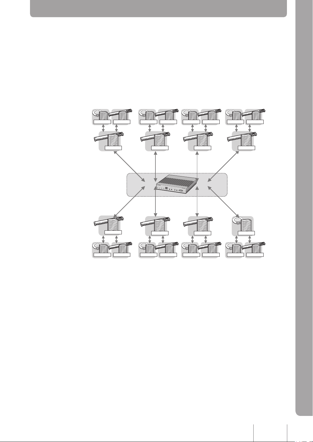
The PJP-MC24 is a Multipoint Audio Control Unit designed exclusively for use with
YAMAHA' s IP phone conference system “ProjectPhone.”
It manages terminal address information and routes calls between terminals. It also
manages conference schedules and automatically establishes connections between
terminals for conferencing.Equipped with the digital mixing function, the PJP-MC24
enables a voice conference with multiple participants by connecting up to 24 ProjectPhones
(or up to 96 ProjectPhones if four PJP-MC24 units are linked).
Introduction
Introduction
Manages address information and routes calls between
terminals
This product manages the address information of individual terminals and routes
connection requests to the appropriate recipients. Even when a terminal’s address is not
fixed (i.e. the address is assigned dynamically by DHCP), it can always be accessed
using the same dialing number. Also, even when calls are made directly between
terminals, this product functions as a SIP server and records information about the calls.
Digital mixing function
Equipped with the digital mixing function, this product is able to connect eight ProjectPhones.
By connecting two PJP-MC24 units to each ProjectPhone, up to 24 ProjectPhones can be
connected for a voice conference with multiple participants.
Link function that supports conferences of varying scales
The link function can be used to connect up to four PJP-MC24 units. When four PJPMC24 units are connected, four conferences, each with 24 participants, can be held
simultaneously, or one conference with 96 participants can be held.
9
Page 10

10
Introduction
Multi-participant voice conference based on interconnection
of ProjectPhones
By using the mixing function of the ProjectPhone instead of the digital mixing function of
the PJP-MC24, up to 30 voice conferences can be held simultaneously, each with
10 participants, independent of conferences that are held using the mixing function of the
PJP-MC24. The audio data trafc is processed directly between each terminal so that the
trafc load never concentrates on a specic participant location.
Enables automated conferencing with conference
management functions and remote control
If you make a conference reservation by selecting the participants and setting the
conference time, this product automatically constructs a conference network by calling up
and connecting to all of the participants’ ProjectPhones. The participants at each location
can join in the conference immediately without bothering to operate their ProjectPhones.
The ad hoc conference function allows up to 10 participants to join a conference without
a reservation, to hold a casual conference where the participants can discuss the topics
freely in an open space.
Audio port
You can also connect an audio device to the audio port on the front panel of the PJP-MC24
to allow the audio device to join the voice conference. Devices equipped with a general
audio interface, such as mobile phones, third-party conference systems and PCs, can be
connected.
Easy to operate
• You can congure this product using its built-in Web interface (GUI screen). Not only
can you use a Web browser on the PC to congure this product, you can also monitor
active conferences and conference participants in real time.
• This product’s front panel indicator LEDs indicate connection problems as well as call
and conference status.
Page 11
Component Names and Functions
POWER ALARM STATUS IN
LAN
CONFERENCE
LINK
/
DATA
SPEED
OUT IN
AUDIO CONSOLE
PROJECTPHONE
21
OUT INIT
1 2 3 4 5 6 7
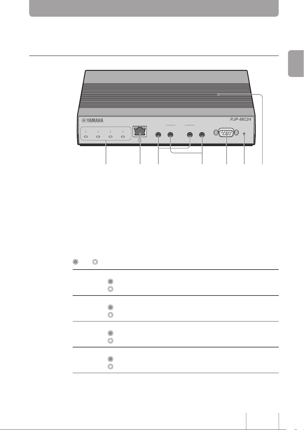
Front
1. LED
Indicates the product’s operating status.
• POWER: Indicates whether or not the product is on. Lights when the PJP-MC24 is on.
• ALARM: Indicates the status of the product.Lights when an error of high priority, such
as a rmware error or memory error, is present.
• STATUS: Indicates the communication status of the product.
• CONFERENCE: Indicates the conference status. Lights when a conference is in session.
Introduction
LED States
Basic indicator LED lighting patterns are listed below.For more information, see “Q1: When
LEDs are off or blinking” (page 78).
POWER LED
The power is on.
The power is off or the product is not receiving power.
ALARM LED
The product is experiencing an error of high priority.
The product is not experiencing an error of high priority.
STATUS LED
There is a problem with the network.
The network is functioning normally.
CONFERENCE LED
A conference is in session. Lights if even one conference is in session.
A conference is not in session.
On Off
11
Page 12

12
Introduction
2. LAN port
For connecting the product to network equipment (such as a personal computer, router or
hub) with a LAN cable.
A LINK LED (left side) and a SPEED LED (right side) are above every LAN port.
• LINK LED: The LINK LED blinks if data is being sent and lights if a link has been
established. If the LINK LED is off, there is no link.
• SPEED LED: The SPEED LED does not light when 10BASE-T is used and lights when
100BASE-TX is used.
3. AUDIO IN terminal
Connect this terminal to the line output terminal on an audio device or PC.
4. AUDIO OUT terminal
Connect this terminal to the line input terminal on an audio device or PC.You can connect
a commercial IC recorder to record voice during a conference.
5. CONSOLE port
Connect the RS-232C terminal (serial connector) on a PC if you want to change the
settings of this product or when you forget your password. For more information, see
“Changing Settings from the CONSOLE Port” (page 74) or “If You Forget Your Password”
(page 85).
6. INIT switch
You can revert your PJP-MC24 to the factory settings by turning on the power while
pressing this switch.
For details, see “Initializing the PJP-MC24” (page 84).
7. Vent holes
Help to prevent overheating.
Page 13
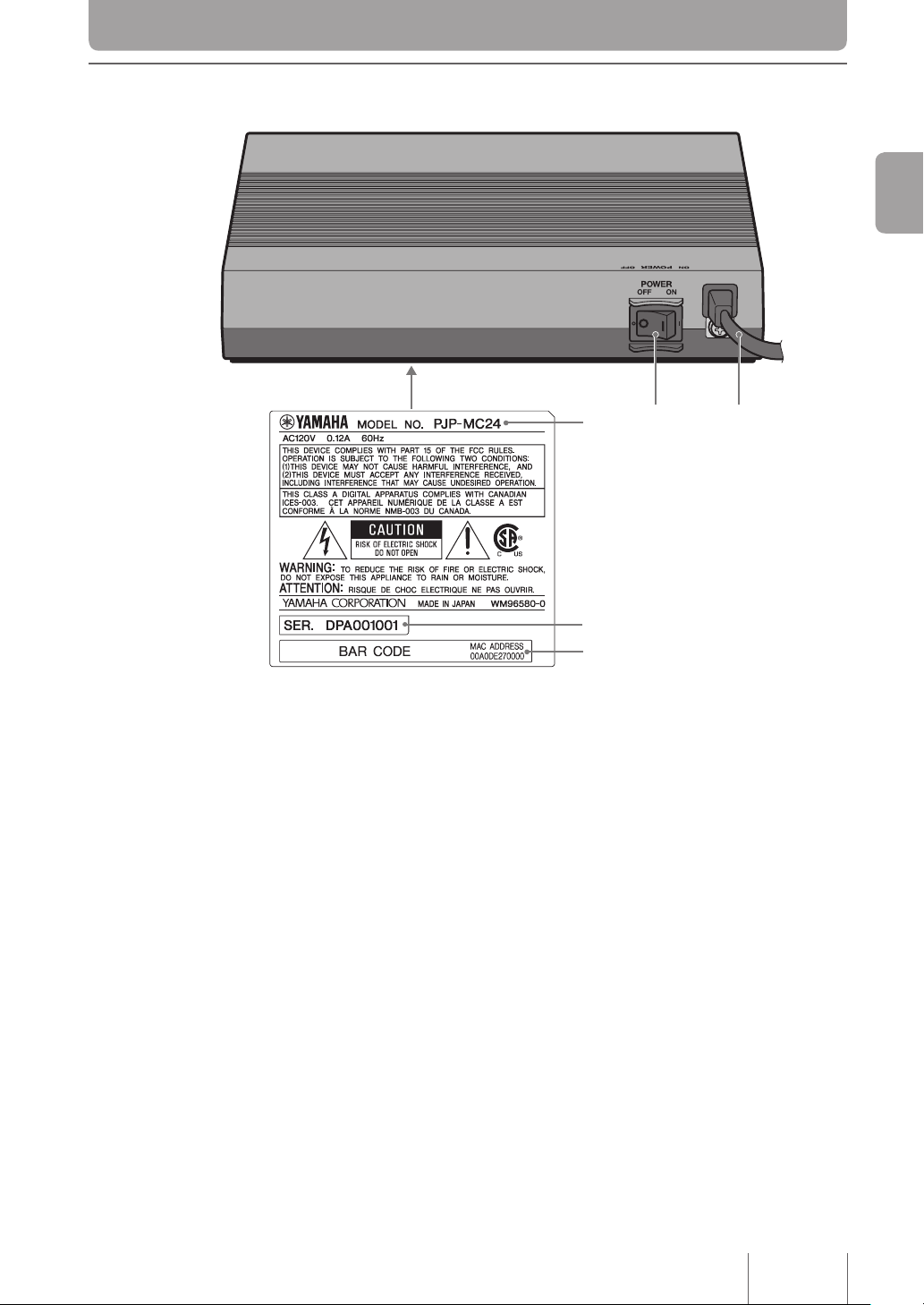
Rear/bottom
4
3
5
1 2
Introduction
1. POWER switch
Turns the power on and off.
2. Power cord
3. Device name
Indicates the product name.
4. Serial number
Indicates the serial number. The serial number is used to identify and manage the product.
5. MAC address
Indicates the unique network ID number for this product’s LAN port.
13
Page 14
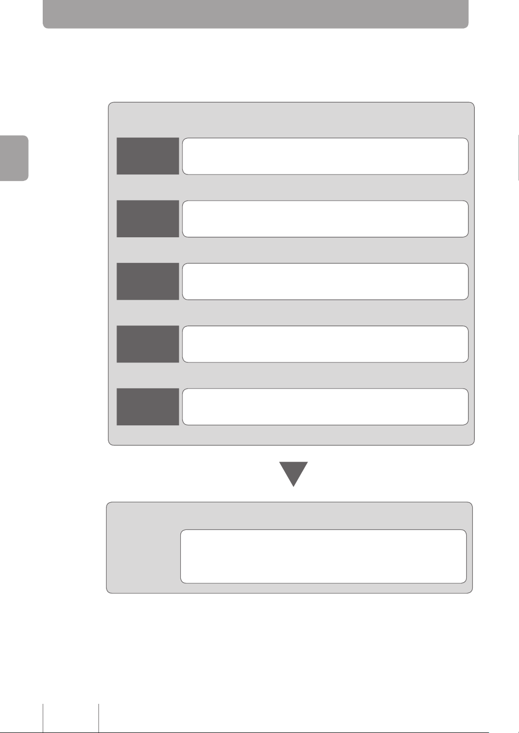
Setup Flowchart
Follow these steps to prepare the product for use.
Connecting the product to a network
Step 1
Getting Started
Connect the product to the host
network and turn the power on.
►
Page
16
▼
Page
Step 2
Accessing the Web interface.
►
17
▼
Page
Step 3
Set passwords for the product.
►
19
▼
Page
Step 4
Set the date and time.
►
21
▼
Page
Step 5
Congure basic network settings.
►
23
14
Setting up a Conference
Configure conference participant settings,
register ProjectPhone information, etc. For more
information, see “Conguration Flowchart.”
►
Page
31
Page 15

Prepare the Following Before You Begin
LAN cable
Obtain a LAN cable compatible with 10BASE-T or 100BASE-TX and make sure the cable
is long enough to cover the distance to the host network.
If you use a commercially available LAN cable, select a STP (Shielded Twisted Pair)
cable.
*This is only applied when used in European region.
Network information
Obtain or determine the following information prior to the installation of this product.
• The administrator password set for this product
• IP address set for this product
• The LAN default gateway and DNS server IP address
Getting Started
Getting Started
15
Page 16
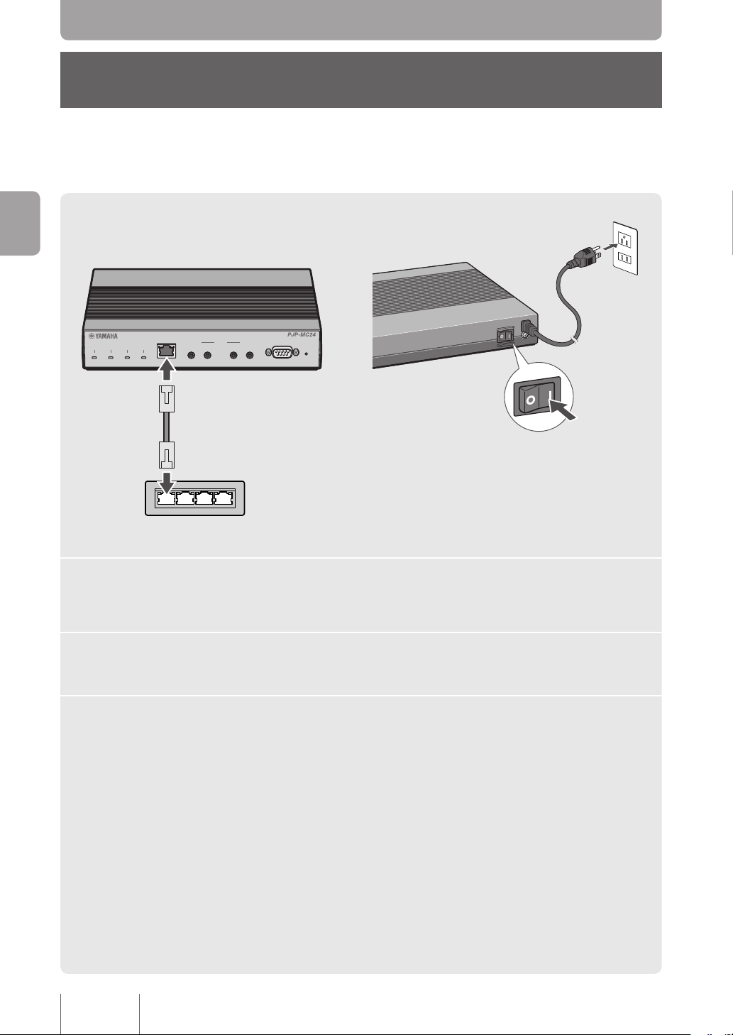
Step 1
POWER ALARM STATUS IN
LAN
CONFERENCE
LINK
/
DATA
SPEED
OUT IN
AUDIO CONSOLE
PROJECTPHONE
21
OUT INIT
O
N
P
O
W
E
R
O
F
F
P
O
W
E
R
O
F
F
O
N
Connecting the PJP-MC24
Getting Started
1
2
3
1
Connect the PJP-MC24 to an AC outlet.
2
3
Connect the LAN ports of the host network and PJP-MC24 using
a LAN cable.
Flip the POWER switch on the PJP-MC24 to ON to turn on the
power.
After all of the LEDs turn on, they will all go off except for the POWER LED.
16
Page 17
Step 2
Note
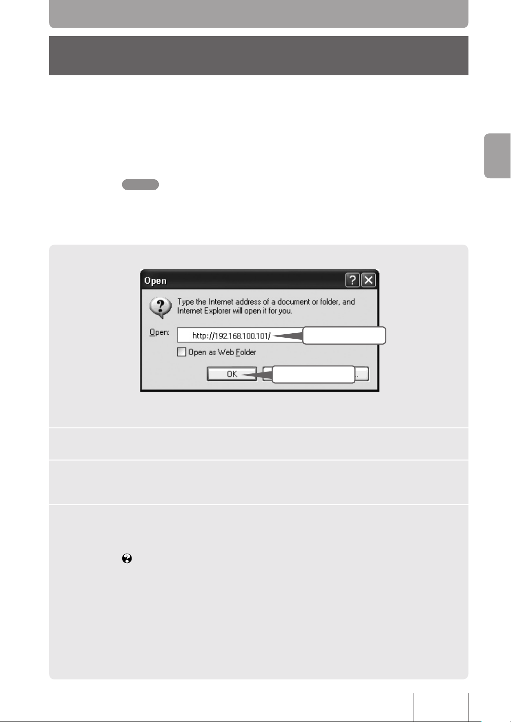
Accessing the Web interface
Congure the PJP-MC24 by connecting it to a PC and using a Web browser to access the
PJP-MC24 Web interface.
You can access the Web interface by following the steps outlined in this section.
To access the Web interface, you need to use a Web browser equivalent to Windows Internet
Explorer 6.0 or later.
Enter
3
Getting Started
Click
3
Conrm that the product is on.
1
Open a Web browser on the PC and click Open on the File menu.
2
Enter “http://192.168.100.101/” using single-byte alphanumerics,
3
and click
The Web interface’s user level main window opens.
If the Web interface’s user level main window does not open,
see “Q2: When the Web Interface is Not Working” (page 80).
OK.
17
Page 18
Getting Started
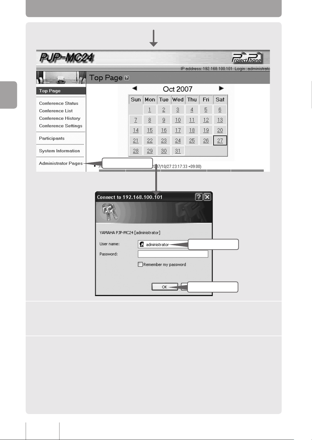
Click
4
Enter
5
Click
5
Click Administrator Pages.
4
Enter “administrator” in the User box, and click OK.
5
18
The Connect to 192.168.100.101 window opens.
You do not need to enter a password.
The Web interface’s administrative main window opens.
Page 19
Step 3
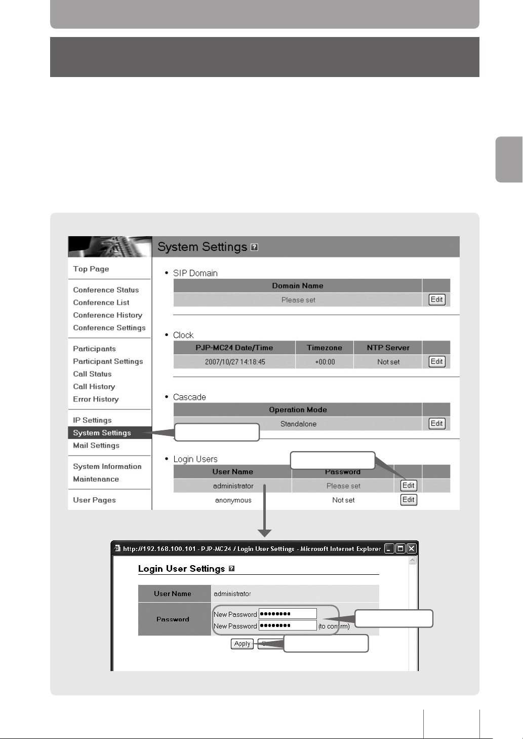
Setting Passwords
The product is not factory set with a login password. For security reasons, we recommend
that you set a password. Setting a password that must be entered for access to the
product will make it more difcult for a third party to tamper with its settings.
Getting Started
1
Click
4
Click
2
Click
3
Enter
19
Page 20

Click System Settings on the Web interface’s user level main
1
window.
The System Settings window opens.
2
Enter the password in the Password box.
Getting Started
3
Click Apply.
4
Click Close.
5
Enter “administrator” in the User box. Enter the password you set
6
Click the Edit button under Login Users next to administrator box.
The Login User Settings window opens.
Each entered character is indicated with a ●.
The set password becomes active, and a conrmation window opens.
The Connect to 192.168.100.101 window opens.
in Step 3 in the
The System Settings window appears again.
Password box. Then click OK.
20
Page 21
Step 4
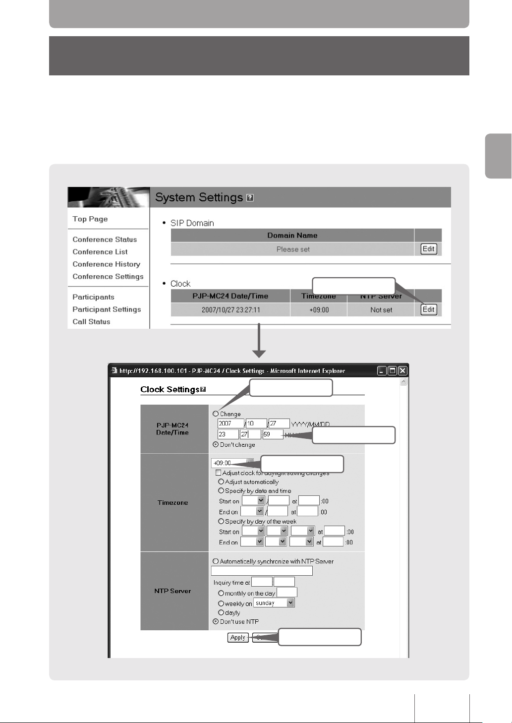
Setting the Date and Time
On the Clock Settings window, you can set the date and time of the PJP-MC24.
Click
1
Getting Started
2
Click
Select
4
5
Click
3
Enter
21
Page 22

On the System Settings window, click Edit under Clock.
Note
1
The Clock Settings window opens.
Click Change next to PJP-MC24 Date/Time.
2
Enter the date and time.
3
Tips
Getting Started
Set the time zone in the Timezone.
4
Click Apply.
5
Click Close.
6
To set the time accurately, set a time slightly ahead of the current time, and then click the
Apply button just as that time is reached.
If you are in Japan, select +09:00.
A conrmation window opens.
The System Settings window appears again.
For areas with daylight saving time
Select the Adjust clock for daylight saving changes check box, and then enter the
daylight saving starting and ending times. For more information, click the help icon on
Clock Settings window.
the
22
Setting the time automatically
You can set the time automatically using an Internet NTP (Network Time Protocol)
server.
For more information, click the help icon on the
The security settings of the LAN network that the PJP-MC24 is located on may not allow it to
use an NTP server to set the time. When using an external NTP server, please congure your
network equipment appropriately. Refer to your network equipment documentation for more
information.
Clock Settings window.
Page 23
Step 5
Note
Conguring Network Settings
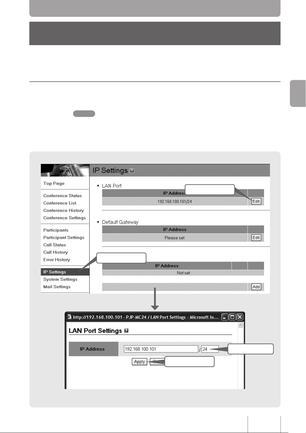
1. Set the LAN Port IP Address of the PJP-MC24
Set an IP address and netmask that conform to the LAN.
The LAN port is factory set to an IP address of 192.168.100.101/24. Be sure to set the product to
an IP address that is not already being used by another device on the LAN.
Click
2
Click
1
Getting Started
4
Click
3
Enter
23
Page 24

Click IP Settings in the Web interface navigation bar.
1
The IP Settings page appears.
Click Edit under LAN port
2
Enter the product IP address.
Getting Started
3
Click Apply.
4
Click Close.
5
The LAN Port Settings window opens.
A conrmation window opens.
You will return to the IP Settings page.
.
24
Page 25
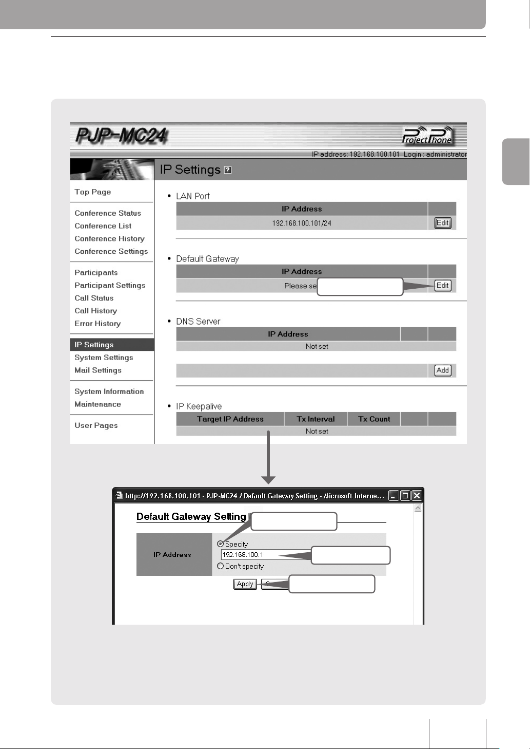
2. Specify a Default Gateway
Specify the default gateway that the PJP-MC24 will use.
1
Getting Started
Click
2
Click
4
3
Click
Enter
25
Page 26

On the IP Settings page, click Edit under Default Gateway.
1
Click Specify.
The Default Gateway Setting window opens.
2
Enter the default gateway.
3
Getting Started
Click Apply.
4
Click Close.
5
A conrmation window opens.
You will return to the IP Settings page.
26
Page 27
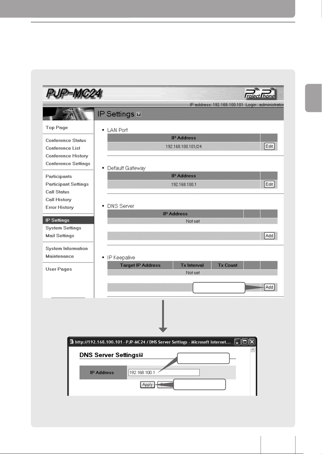
3. Specify a DNS Server
Specify the DNS servers that the PJP-MC24 will use. You can set a maximum of four
DNS servers.
Getting Started
3
2
Click
1
Enter
Click
27
Page 28

On the IP Settings page, click Add under DNS Server.
1
Enter the DNS server IP address in the IP Address box.
The DNS Server Settings window opens.
2
Click Apply.
3
Getting Started
Click Close.
4
A conrmation window opens.
You will return to the IP Settings page.
28
Page 29

4. Specify IP Addresses to be Checked with IP Keepalive
Congure the IP Keepalive feature of the PJP-MC24 as necessary. The PJP-MC24 will
search for network errors by sending an ICMP Echo request at a specied time interval to
the IP addresses you select here. When the PJP-MC24 detects a network error, its front
panel STATUS LED will light.
Tips
You can also congure the product to send an error notication mail (page 69).
Getting Started
2
4
Enter
3
Click
Click
1
Select
29
Page 30

On the IP Settings page, click Add under IP Keepalive
1
Enter the ICMP Echo request target IP address in the Target IP
2
The IP Keepalive Settings window opens.
Address box.
Enter the IP address of a device whose connection you want to check (for example,
the default gateway IP address).
.
Getting Started
Specify the transmit interval and count in the Transmit Interval
Transmit Count boxes as necessary.
3
Click Apply.
4
Click Close.
5
and
Transmit Interval
You can specify the interval between ICMP Echo transmissions in seconds. If the PJPMC24 receives an ICMP Echo Reply before the next Echo request transmission, the
address passes. If no reply is received, the address fails.
Transmit Count
Sets the number of ICMP Echo request transmissions that will be sent. If the PJPMC24 does not receive an ICMP Echo reply for the number of transmissions set under
Transmit Count, the IP address is considered invalid.
A conrmation window opens.
You will return to the IP Settings page.
30
Page 31

Conguration Flowchart
Continue on to these steps to congure the PJP-MC24 for use.
Congure all devices.
Step 1
Step 2
Step 3
Step 4
Set the SIP domain name (for the
PJP-MC24).
▼
Specify participant information (for the
PJP-MC24).
▼
Conguring ProjectPhones
▼
Conrming Settings
Page
Page
Page
Page
Setting up a Conference
33
35
Setting up a Conference
43
48
31
Page 32

Prepare the Following Before You Begin
32
Setting up a Conference
Participant setup information
Configuration will be easier if you determine or acquire the following participant
information before you begin.
• The names you will assign to participants
• The location numbers you will assign to participants
• Whether or not you will require authentication
• The authentication password that you will use
PJP-MC24 setup information
This information will be necessary when conguring the participants’ ProjectPhones.
• IP address of the PJP-MC24 (page 23)
• The SIP domain name to be set in the PJP-MC24 (page 33)
About location number limitations
If a participant sets the PJP-50R to use zero as the PSTN (public switched telephone
network) prex, then you will not be able to use location numbers that start with zero,
such as “01” or “0050”. For more details, please see the PJP-50R Basic Operation Guide.
Page 33

Step 1
Setting the SIP Domain Name
Set the PJP-MC24's SIP domain name. The SIP domain name is a group identier that
enables participants’ ProjectPhones to connect to the PJP-MC24.
Click
2
Setting up a Conference
4
Select
1
Click
3
Click
Click
5
33
Page 34

Click System Settings on the Web interface’s main window while
34
Setting up a Conference
1
logged in as an administrator.
The System Settings window opens.
Click Edit under SIP Domain
2
Click Specify.
The SIP Domain Setting window opens.
.
3
Enter the SIP domain name.
4
Click Apply.
5
Click Close.
6
The SIP domain name functions as a group identifier that enables participants’
ProjectPhones to connect to the PJP-MC24.When assigning SIP addresses to
participants’ ProjectPhones (see page 45), use the SIP domain name specied here.
Tips
Because the SIP domain name is not resolved by the DNS, you can set it to any name that you
like (“PJP-NETWORK” for example).
A conrmation window opens.
The System Settings window appears again.
Page 35

Step 2
Specifying Participant Information
You can set participant information one location at a time on the Participant Settings
window (500 participants max.
Tips
• You can also download participant information in CSV le format, use a spreadsheet program
such as Microsoft Excel to edit the information, and set the edited information to the PJP-MC24
(page 37).
• After you have registered participants, you can also register participant groups. Participant
groups are useful for arranging participants according to the kinds of conferences that they
participate in. Participant groups can help you avoid making mistakes when selecting the
participants for a particular conference.
).
Setting up a Conference
1
Click
7
Click
2
3
4
5
Click
Select
Select
Select
6
Select
35
Page 36

Click Participant Settings on the Web interface’s main window
Note
Note
Note
Note
36
Setting up a Conference
1
Click Add under Participants.
2
while logged in as an administrator.
The Participant Settings window appears.
The Participant Settings window opens.
Enter the location number in the Number box (max. 16 characters).
3
• Location numbers do not have to all have the same number of digits.
• Numbers starting from the prex for ad hoc conference (page 66) (default: 1111) cannot be
Enter a participant name in the Participant box if necessary.
4
Select ProjectPhone in the Terminal Type box.
registered as participant numbers.
Enter the participant name that is displayed in places such as the Participants page
(max. 32 characters; can be omitted).
Participant names cannot contain “&”, “=”, “+” and “%”.
5
The Other SIP Terminal option is for future expansion.
In Authentication, specify whether or not the PJP-MC24 will require
6
authentication to answer participant requests.
• Digest authentication: Digest authentication is performed. You must set a password.
• No authentication: Authentication is not performed.
• Set a password other than the password for the product (page 19).
• You can select different passwords for each participant.
• Passwords cannot contain “&”, “=”, “+” and “%”.
Click Apply.
7
If you want to enter the information for another participant, click
8
When you have nished entering participant settings, click Close.
The set participant information is saved, and a Conrmation window opens.
Add another participant and repeat steps 3 through 7.
9
Page 37

Using a CSV File to Congure All Participant
Settings
1. Create a participant information le.
After downloading a template CSV le, you can congure participant information all at
once by using a spreadsheet program such as Microsoft Excel.If you want to use the Web
interface to set individual participant information, such as making minor adjustments to the
information you have already set, see page 35.
Click
1
Setting up a Conference
5
Click
2
Click
3
Click
37
Page 38

Click Participant Settings on the Web interface’s main window
38
Setting up a Conference
1
Under Participant Settings Management click Execute next to
2
Right click Participant Settings CSV File and click Save
3
while logged in as an administrator.
The Participant Settings page appears.
Output Settings to CSV File
The Output Participant Settings to CSV File window opens.
Target As.
.
Specify the lename and save location, and then save the CSV le.
4
Click Close.
5
You will return to the Participant Settings page.
Page 39

2. Enter participant information.
Note
Use a spreadsheet program such as Microsoft Excel to enter all participant information
into the template CSV le. You can input information for up to 500 participants.
Data entry guidelines
Follow these guidelines when entering participant information.
1. Put quotation marks around the location number.
If you do not do this, you may experience problems when assigning location numbers
that start with zero, because Microsoft Excel automatically deletes preceding zeros.
× (0166) ○ (“0166”)
Tips
You do not need to put quotation marks around location numbers that do not start with zero.
However, the PJP-MC24 automatically puts quotation marks around all numbers when
saving data to a CSV le.
• If one of the participating terminals is a PJP-50R, see page 32 for special considerations
that need to be made when choosing location number prexes.
• Do not surround location numbers with quotation marks when entering them in the Web
interface.
2. How the PJP-MC24 handles blank spaces
• The spaces before and after character data are not recognized as data.
• Spaces inside of quotation marks are recognized as data.
• Spaces contained within characters other than commas are recognized as data.
“TokyoOfce” will be read as “TokyoOfce”
Tokyo Ofce will be read as “Tokyo Ofce”
3. How the PJP-MC24 handles single quotation marks, double quotation marks,
and commas.
They can all be used within character data.
○ Chicago’Ofce ○ Paris“Ofce ○ Beijing,Ofce
Setting up a Conference
4. Lines that begin with a pound sign will be treated as comment lines.
5. Line feed code
CSV files are designed to be created and edited using Windows. They only use
CR+LF newline.
39
Page 40

Open the CSV le that was saved in “1. Create a Participant
Note
Note
Note
40
Setting up a Conference
1
Information File” (page 37) using a spreadsheet program such as
Microsoft Excel.
You can open the le with any spreadsheet program or text editor that is capable of
handling CSV le format.
Enter participant information and save the le
2
The following is an explanation of how to edit participant information using Microsoft
Excel.
.
Column A: Location number
Enter the participant’s location number in column A (max. 16 characters).
Also read “About location number limitations” (page 32) before setting a location number.
• Location numbers do not have to all have the same number of digits.
Column B: Participant name
Enter the participant name that is displayed in places such as the Participants page
(max. 32 characters; can be omitted).
Participant names cannot contain “&”, “=”, “+” and “%”.
Column C: Terminal type
Enter the type of terminal that is installed at the participant location.
• pjp: A ProjectPhone
• non-pjp: Reserved for future expansion
Column D: Authentication
Specify whether or not the PJP-MC24 will require authentication to answer participant
requests.
• Blank: Digest authentication. Enter a password in column E.
• “none”: No authentication.
Column E: Password
If the participant is set to digest authentication (column D is left blank), enter a password
here.
Passwords cannot contain “&”, “=”, “+” and “%”.
Page 41

3. Upload the participant information le.
Note
Upload the CSV le that you created to the PJP-MC24, and use it to congure participant
information settings.
Please be aware that when you upload a CSV le, it overwrites all participant information that was
stored on the PJP-MC24.
Names of les to be uploaded should not contain “&”.
Click
1
Setting up a Conference
5
2
Click
Click
3
Click
41
Page 42

Click Participant Settings on the Web interface’s main window
42
Setting up a Conference
1
Under Participant Settings Management click Execute next to
2
Click Browse.
3
while logged in as an administrator.
The Participant Settings window appears.
Input Settings to CSV File
The Input Participant Settings from CSV File window opens.
The Choose le window opens.
.
Select the le that you used in “2. Enter participant information”
4
Click Upload.
5
Click Close.
6
Conrm that the CSV le’s participant information is listed properly
7
(page 39) and click
The PJP-MC24 will load the participant information from the le that you selected in
step 4.
You will return to the Participant Settings window.
The participant information settings are now complete.
under
If it is displayed properly, the participant information settings are complete.Please
proceed to “Step 3: Changing ProjectPhones Settings” (page 43).
If the information listed under Participants is incorrect:
If the participant information is not entered properly into the CSV le, the information will
not be congured properly.
Correct the CSV le, and then upload the le again.
Participants.
Open.
Page 43

Step 3
Note
Changing ProjectPhone Settings
After participant information has been configured on the PJP-MC24, configure the
participants’ ProjectPhones to join conferences via the PJP-MC24.
Conguration Flowchart
Follow these steps to congure the participants’ ProjectPhones.
1. Set the IP address (next page).
Set the IP address, netmask, and default gateway that the ProjectPhone will use.
2. Register SIP server information (page 45).
Congure the participant’s ProjectPhones so that they refer to the PJP-MC24 as a SIP
server.
3. Enable remote control from the PJP-MC24 (page 47).
Congure the ProjectPhone to accept control signals from the PJP-MC24 used to start
conferences.
• Before performing the following operations, you need to congure the ProjectPhones network
connection settings. For more details, please see the ProjectPhone Setup Guide.
• The following explanation gives examples of how the settings would be congured using the
PJP-100H ProjectPhone.
If a participant is using a PJP-50R:
If you are using a PJP-50R and want to make calls directly to other ProjectPhones, then
you need to pay special attention to the PJP-50R dialing prex settings.
• You can use prexes to identify the type of network that you want to call to. To dial other
ProjectPhones, you enter the IP network prex, followed by the location number. If you
choose not to specify a prex for IP network calls, you can call other ProjectPhones by
simply entering their location numbers.
• However, if location numbers start with network prex numbers (for example a network
prex is set to zero and there is a location number “0010” then you will have to change
the PJP-50R dialing prex settings in order to reach those location numbers. For more
details, please see the PJP-50R Basic Operation Guide.
Setting up a Conference
43
Page 44

1. Set the IP Address
44
Setting up a Conference
Use the ProjectPhone keys to set the IP address, netmask, and default gateway that the
ProjectPhone will use. For more information, see “Step 2: Registering the network settings
of this unit” (PJP-100H) or “Step 2: Registering the settings of this unit” (PJP-50R) in the
ProjectPhone Basic Operation Guide.
Tips
You can use a DHCP server instead of setting a xed IP address. This will not interfere with
conferences in any way.
When you have nished entering the settings
Conrm the settings and connection status on the ProjectPhone display. For more details,
please see the ProjectPhone Basic Operation Guide
.
Page 45

2. Register SIP Server Information
Congure the participant’s ProjectPhones so that they refer to the PJP-MC24 as a SIP
server.You will need to know the PJP-MC24 settings, such as the SIP domain name, so
obtain this information before you start.
Setting up a Conference
8
Click
4
Click
3
Click
5
6
7
Enter
Enter
Enter
45
Page 46

Connect the ProjectPhone to the PC you will use to congure it.
46
Setting up a Conference
1
Open a Web browser and enter “http://<ProjectPhone’
2
Click SIP Server.
3
Set SIP Server to Enable.
4
In the SIP Server Name box, type the PJP-MC24 IP address.
5
In the SIP Server Password box, enter the authentication
6
s_IP_address>” into the address bar.
The ProjectPhone Web Settings page appears.
The SIP Server page appears.
Enter the IP address that has been assigned to the PJP-MC24 LAN port (page 23).
password.
If an authentication password has been set using the PJP-MC24 Participant Settings
(page 36), enter that password. If
password box blank.
No Authentication has been selected, leave the
In the SIP Address box, enter the ProjectPhone’s SIP address in
7
Click Submit.
8
the following format: sip: (location number)@(PJP-MC24 SIP
domain name).
• Location number: The location number for the participant using the ProjectPhone
(page 36).
• SIP domain name: The domain name set on page 34.
SIP address example
If the participant using the ProjectPhone has the location number 0010, and the SIP
domain name is PJP-NETWORK, the SIP address would be “sip:0010@PJPNETWORK”.
Check the ProjectPhone display and make sure that it is connected properly to the
PJP-MC24.
Page 47

3. Enable Remote Control from the PJP-MC24
Note
Congure the ProjectPhone to accept control signals from the PJP-MC24 used to start
conferences.
• If you do not congure the ProjectPhone to allow remote control from the PJP-MC24, it will not
be able to participate in scheduled conferences. Be sure to enable remote control.
• If a password is set for the ProjectPhone, the PJP-MC24 cannot implement communication
control even when the remote control is enabled. Cancel the ProjectPhone password, if set.
To allow remote control, follow these steps using the ProjectPhone keys:
On the initial screen, press the
1
Press the or
2
Press the or
3
Press the or
4
Press the
5
The Menu screen appears.
key and select Settings, and then press the
key.
The Settings menu screen appears.
key and select General Settings, and then press
the
The General Settings screen appears.
the
The Remote Control screen appears.
Remote control from the PJP-MC24 is now enabled.
key.
key.
key.
key and select Remote Control, and then press
or
key and select Enable, and then press the
key.
Setting up a Conference
47
Page 48

Step 4
Conrming Settings
After you have completed the product and ProjectPhone settings, confirm that the
participants are registered properly.
Setting up a Conference
Click
1
Click Participants on the Web interface’s main window while
1
Make sure that all of the participants that were congured on
2
Conrm that the Status column lists all participants as being
3
logged in as an administrator.
The Participants page appears.
page 35 are listed under
Registered.
Conrm
2
Conrm
3
Participant Information.
48
If a participant is listed as “Not registered”
• The PJP-MC24 has not registered the participant. Please review pages 33 to 47 and
conrm that the ProjectPhone is congured properly and that the correct participant
conguration information has been entered into the PJP-MC24.
• Conrm that the participant’s ProjectPhone is on.
• Conrm that the participant’s ProjectPhone is connected properly to the network.
If “Error” is displayed under the status column
See “Troubleshooting” on page 77.
Page 49

Overview of Conference Using
PO
WER
ALARM
ST
A
TUS
IN
LAN
CONFERENCE
LINK
/
D
A
T
A
SPE
ED
OUT
IN
A
UDIO
CONSOLE
PR
OJECTPHONE
2
1
OUT
INIT
PJP-MC24
Participant M
1
2
3
4
5
6
7
8
9
0
MIC MUTE
VOL
Participant N Participant O
1
2
3
4
5
6
7
8
9
0
MIC MUTE
VOL
Participant V
1
2
3
4
5
6
7
8
9
0
MIC MUTE
VOL
Participant W Participant X
Participant P
1
2
3
4
5
6
7
8
9
0
MIC MUTE
VOL
Participant Q Participant R
Participant S
1
2
3
4
5
6
7
8
9
0
MIC MUTE
VOL
Participant T Participant U
1
2
3
4
5
6
7
8
9
0
MIC MUTE
VOL
Participant B
Participant A
Participant C
1
2
3
4
5
6
7
8
9
0
MIC MUTE
VOL
Participant E
Participant D
Participant F
1
2
3
4
5
6
7
8
9
0
MIC MUTE
VOL
Participant H
Participant G
Participant I
1
2
3
4
5
6
7
8
9
0
MIC MUTE
VOL
Participant K
Participant J
Participant L
(Audio mixing and conference control)
the PJP-MC24
Types of Conferences You Can Hold with the
PJP-MC24
Two types of conferences can be held with the PJP-MC24: Mixer conference and local
conference. You can select the conference type according to the number of participants
and other conditions.
Tips
For conferences not requiring a reservation, see “Starting a Conference without a Reservation”
(page 65).
Mixer Conference
The mixing function of the PJP-MC24 is used to connect ProjectPhones at a maximum of
24 locations.
• Multiple mixer conferences cannot be held simultaneously if only one PJP-MC24 unit is used.
• When Cascade (page 64) is used to link four PJP-MC24 units, you can hold up to four
mixer conferences simultaneously, each with 24 participants, or one mixer conference
with 96 participants.
Starting a Conference with a Reservation
Starting a Conference with a Reservation
Local Conference
The mixing functions of the participant's terminals (ProjectPhones) can be used to hold up
to 30 conferences in addition to mixer conferences. Local conferences are classied into
the mesh connection type and the cascade connection type.
• The PJP-MC24 schedules conferences, manages participants and conference
resources, and constructs the conference network.
• Once connection has been established between the participants, they transfer audio
data directly with each other without going through the PJP-MC24.
49
Page 50

Mesh Connection
Scheduled Conference
Start Time
Scheduled Conference
End Time
Time
Automatic Calling
Participant and Topology Setup
Conference in Session
(Extension)
1
2
3
4
5
6
7
8
9
0
MIC MUTE
VOL
1
2
3
4
5
6
7
8
9
0
MIC MUTE
VOL
Participant A Participant B
Participant C Participant D
Audio Signal
Audio Signal Audio Signal
Audio Signal
Audio Signal
Audio Signal
PO
WER
ALARM
ST
A
TUS
IN
LAN
CONFERENCE
LINK
/
D
A
T
A
SPE
ED
OUT
IN
A
UDIO
CONSOLE
PR
OJECTPHONE
2
1
OUT
INIT
PJP-MC24
(Conference control
signal only)
Server
1
2
3
4
5
6
7
8
9
0
MIC MUTE
VOL
Participant 5 Participant 6
ClientClient
Participant 2
1
2
3
4
5
6
7
8
9
0
MIC MUTE
VOL
1
2
3
4
5
6
7
8
9
0
MIC MUTE
VOL
Participant 9 Participant 10
ClientClient
Server
Participant 4
1
2
3
4
5
6
7
8
9
0
MIC MUTE
VOL
Participant 7 Participant 8
ClientClient
Server
Participant 3
1
2
3
4
5
6
7
8
9
0
MIC MUTE
VOL
Audio Signal Audio SignalAudio Signal
Server
PO
WER
ALARM
ST
A
TUS
IN
LAN
CONFERENCE
LINK
/
D
A
T
A
SPE
ED
OUT
IN
A
UDIO
CONSOLE
PR
OJECTPHONE
2
1
OUT
INIT
PJP-MC24
(Conference control
signal only)
Participant 1
50
Starting a Conference with a Reservation
In a mesh network, a communication path is established between each participant. The
PJP-MC24 can connect up to four participants on this type of network.
Cascade Connection
Up to 10 participants can be cascaded-connected. The PJP-MC24 automatically sets
server and client terminals based on the number of participants.
Conference Flowchart
Schedule a conference by specifying the conference participants and the starting time.
• At the scheduled conference start time, the PJP-MC24 will automatically connect to the
participants and construct the conference network.
• Scheduled conferences will be held according to the following process.
Tips
You can manually start a conference without waiting for the scheduled conference start time
(page 59). However, you still must make a conference reservation and register all conference
participants.
Page 51

Registering a Conference Time and Participants (Reserving a Conference)
To hold a conference, you have to make a reservation by specifying the participant
information and the conference date and time.
Reserving a Conference
Click
1
Click
2
Starting a Conference with a Reservation
5
Enter
Click
7
3
Click
4
Enter
6
Select
51
Page 52

Click Top Page in the Web interface navigation bar.
52
Starting a Conference with a Reservation
1
Click the day on the calendar on which you want to hold
2
Click the Add button under Scheduled Conferences.
3
The Top Page appears.
Top Page calendar, the current date is surrounded by a red box.
On the
a conference.
The selected date will be surrounded by a blue box (if today’s date is selected, it will be
surrounded by a purple box).
To choose a date in a different month, click the triangles above the calendar to switch to
that month.
The Add/Edit Conference Schedule window opens.
Enter the conference name in the Name box.
4
Enter the conference number used to identify the conference in the
5
Click Specify next to Date/Time, and enter the conference start time.
6
Click the Select button next to Participants.
7
You can enter up to 128 characters.
Number box (max. 4 digits).
After conrming the conference date, enter the conference start time (to the nearest
quarter hour).
Tips
• If you want to make a reservation for a recurring conference, see “Setting Up a Recurring
Conference” (page 55).
• You can make a conference reservation without specifying the conference date and time.
However, you will have to initiate the conference manually (page 59).
The Add/Edit Conference Schedule/Participants window opens.
Page 53

9
Click
8
Select
哈
Select the conference participants.
8
If a participant group has been set up, a list of participant groups will be displayed
above the list of individual participants. Select or clear a participant group check box to
select or deselect all of the participants in that group.
15
12
13
Click
10
11
Click
Select
14
Select
Select
Enter
Starting a Conference with a Reservation
Click Apply.
9
You will return to the Add/Edit Conference Schedule window.
53
Page 54

From the Audio Port, select the PJP-MC24 audio port check box
54
Starting a Conference with a Reservation
10
Select the conference type from the Type list.
11
to be used.
The device connected to the selected audio port can connect to the audio channel used
for the conference.
Select the conference type based on the number of participants.
• Max. 4 ('ProjectPhone' series only): A local conference of mesh type (page 50) is
held.
• Max. 10: A local conference of cascade type (page 50) is held. The PJP-MC24 will
automatically connect all participants by setting server and client terminals based on the
number of participants.
• Max. 24: A mixer conference (page 49) is held independently by the PJP-MC24.
• Max. 48/72/96: A mixer conference is held using Cascade (page 64).
Click Reservation Inquiry.
12
If necessary, select a participant that you want at the center of the
13
Enter information into the (Owner), (Contact), and (Description)
14
The Add/Edit Conference Schedule / Reservation Inquiry window opens.
This window displays a reservation graph with each day broken into units of 15 minutes.
Unreserved time slots are colored green, while reserved time slots are colored red.
If you cannot reserve a conference because resources or participants are unavailable,
you can use this window to nd out what the problem is and to search for open time
slots.
network topology from the
you selected
The PJP-MC24 will construct the topology around the selected central participant
(selection of a central participant is optional).
boxes as necessary.
You can enter supplementary conference information (optional).
You can type up to 24 characters in the
128 characters in the
Max. 10 for the conference type in step 11).
(Description) box.
Center Participant list (only available if
(Owner) and (Contact) boxes and up to
15
Click Apply.
You have made a conference reservation.
Page 55

Setting Up a Recurring Conference
You can reserve weekly and other recurring conferences for up to half a year.
3
4
2
Enter
Select
Select
Click
5
Click Repeat in the Add/Edit Conference Schedule window
1
Select the Repeat check box and then select the frequency of
2
Enter the day when conference repetition will end in the End
3
If necessary, select dates that are exceptions and will not be
4
(page 51).
The Add/Edit Conference Schedule / Repeat Setting window will appear.
repetition (
Day box.
You can enter an ending day that is up to half a year after the rst conference day.
reserved.
You can select up to 5 dates by using the following format: YYYY/MM/DD (example:
2007/10/10)
Tips
To except six or more dates, please adjust the ending date (End Day) for the recurring
conference, and make a new reservation for the later dates.
Every day/Every week/Every month).
Starting a Conference with a Reservation
Click Apply.
5
You will return to the Add/Edit Conference Schedule page.
The conference repetition conditions will be displayed to the right of the
Repeat button.
55
Page 56

Deleting a Conference Reservation
Note
56
Starting a Conference with a Reservation
If a conference has been canceled, delete the conference reservation.
1
Click
Click
2
On the Top Page, click Delete next to the conference reservation
1
Click Delete.
2
listed under
The Delete Scheduled Conference window opens.
The conference reservation will be deleted.
You cannot delete a reservation for an active conference.
To delete a repeating conference
Repeating conference reservations can only be deleted from the Conference List page
(accessed by clicking
from the
repeating conference’s excepted days list (and the repeating conference itself will not
be deleted).
Scheduled Conferences that you want to delete.
Conference List on the main window). If you delete a conference
Top Page that is part of a repeating conference, it will be added to the
Page 57

Starting a Conference
You can start a conference after you have reserved it.
Starting a Conference According to Schedule
You can start a reserved conference at the scheduled time without operating the PJPMC24. The following explains the connection process for participants.
Prepare the ProjectPhone for the Conference.
1
• Turn on the ProjectPhone and connect its LAN cable, so that it will be able to connect to
the PJP-MC24.
• Disconnect the ProjectPhone from all other terminals.You can check the ProjectPhone
display to see whether or not the ProjectPhone is connected to other terminals and
whether or not it will be able to connect to the PJP-MC24.
Pre-conference Conference Status page display
The Participants list on the Conference Status (page 60) page displays Will attend
in the status of scheduled conference participants.
Starting a Conference with a Reservation
57
Page 58

Wait for the PJP-MC24 to Establish a Connection
Note
Note
58
Starting a Conference with a Reservation
2
When the schedule time arrives, the PJP-MC24 automatically calls the terminals of the
participants.
The PJP-MC24 will automatically establish a connection, so there is no need to operate
the ProjectPhone or to try to call the product. When the PJP-MC24 calls a terminal, the
ProjectPhone will ring briey before automatically connecting to the network.
The PJP-MC24 builds the network topology at the start of the conference, so participants will
not be able to connect to the product before it has established a connection with them. Please
wait for the PJP-MC24 to establish a connection.
Conference Status page display after participants have
been called
The status of scheduled conference participants is listed as Inviting.
Start the Conference
3
• The MIC MUTE is automatically switched on once connection has been established. Before
the conference starts, use the
• If a server is disconnected while a conference is in session, the clients that are connected to
the server will also be disconnected. The line will be connected automatically, so please wait.
Conference Status page display once the conference
has started
Conference participants are listed as Attending.
If the Conference Does Not Start
See “Q3: When You Cannot Hold a Conference” (page 82).
MIC MUTE button to switch MIC MUTE off.
Page 59

Starting a Conference Before the Scheduled
Note
Start Time
To start a conference immediately without waiting for the scheduled conference start time,
follow these steps on the Web interface.
Click
1
Starting a Conference with a Reservation
Click
2
On the Top Page under Scheduled Conferences, click the name
1
Click the Start button under Operation.
2
Select the conference duration, and then click Start.
3
of the scheduled conference that you want to start.
The Conference Status page appears.
The Start Conference window opens.
The PJP-MC24 will begin conference preparation.
The PJP-MC24 will finish preparing in about 10 seconds and will then start calling
participants.
It may not be possible to start the selected conference using this method if another conference
is already in session.
59
Page 60

Operations during Reserved
60
Starting a Conference with a Reservation
Conference
Checking Conference Status
You can check the status of an active conference on the Conference Status page.
Conference Status page shows you information such as participant status and
The
conference reservation details.
Click
Conference
information
Participant
information
Click Conference Status on the main window.
The Conference Status page appears.
Monitoring a conference in real time
Click Monitor on the Conference Status page to open the Monitor Conference
window.
Set the
Refresh Interval and then click Start to begin monitoring the conference.
Page 61

Extending a Conference
Note
To extend a conference beyond the scheduled conference end time, follow these steps on
the Web interface.
1
Click
Starting a Conference with a Reservation
Select
2
Click
2
On the Conference Status page (see previous page), click
1
Select the amount of time for which you want to extend the
2
Extend under Operation.
The Extend Conference window opens.
conference, and then click
The conference time will be extended.
It may not be possible to extend the selected conference using this method if another
conference is already in session.
Execute.
61
Page 62

Changing the Participants in an Active
62
Starting a Conference with a Reservation
Conference
You can add or remove participants in an active conference.
Points to consider when changing participants
Different limitations apply to changing participants, depending on which conference type
you selected on the
When the conference type is Max. 4 (Project Phone series only)
• You can add or remove participants as long as the number of participants stays at
4 or below.
• If you want to add more than four participants, you will have to temporarily stop the
conference and switch the conference type to
When the conference type is Max. 10
• You can add or remove participants as long as the number of participants stays at
10 or below.
On the Conference Status page (page 60), click Edit under
1
• Removing a server terminal may cause the clients connected to it to be disconnected.
The line will be connected automatically, so please wait.
Schedule.
Add/Edit Conference Schedule window (page 51).
Max. 10.
The Add/Edit Conference Schedule window opens.
Change the participants.
2
To add new participants
• Click the Select button next to Participants to open the Add/Edit Conference
Schedule / Participants window.
• Click to put a check next to the participants that you want to add, and click
To remove participants from a conference
Remove the checks that are next to the participants that you want to remove.
Click Apply.
3
The participants specied in step 2 will be added or removed.
Apply.
Page 63

Ending a Conference
Ending a Conference at the Scheduled
Ending Time
No operation is necessary.
When the conference ending time is reached, the PJP-MC24 automatically disconnects
all participants.
Ending a Conference Immediately
Follow these steps on the Web interface:
Click
1
Starting a Conference with a Reservation
Click
2
On the Conference Status page (see page 60), click Terminate
1
Click Execute.
2
under
The Terminate Conference window opens.
The PJP-MC24 will end the conference.
To ensure that they disconnect, all participants should close their connections by
pressing the ProjectPhone hang-up button.
Operation.
63
Page 64

Increasing the Number of Mixer
Participant
Participant
Participant
Participant
Participant
Participant
Participant
Participant
Participant
Participant
Participant
Participant
Participant
Participant
Participant
Participant
Participant
Participant
Participant
Participant
Participant
Participant
Participant
Participant
Participant
Participant
Participant
Participant
PO
WER
PO
WER
ALARM
ST
A
TUS
IN
LAN
CONFERENCE
LINK
/
D
A
T
A
SPE
ED
OUT
IN
A
UDIO
CONSOLE
PR
OJECTPHONE
2
1
OUT
INIT
PJP-MC24
Participant
1
2
3
4
5
6
7
8
9
0
MIC MUTE
VOL
Participant Participant
1
2
3
4
5
6
7
8
9
0
MIC MUTE
VOL
Participant
1
2
3
4
5
6
7
8
9
0
MIC MUTE
VOL
Participant Participant
Participant
1
2
3
4
5
6
7
8
9
0
MIC MUTE
VOL
Participant Participant
Participant
1
2
3
4
5
6
7
8
9
0
MIC MUTE
VOL
Participant Participant
1
2
3
4
5
6
7
8
9
0
MIC MUTE
VOL
Participant
Participant
Participant
1
2
3
4
5
6
7
8
9
0
MIC MUTE
VOL
Participant
Participant
Participant
1
2
3
4
5
6
7
8
9
0
MIC MUTE
VOL
Participant
Participant
Participant
1
2
3
4
5
6
7
8
9
0
MIC MUTE
VOL
Participant
Participant
Participant
• Master x 1 unit
• Slave x 3 units
Conference Participants
(Cascade)
You can hold a mixer conference with up to 96 participants by linking up to four PJPMC24 units.
Starting a Conference with a Reservation
64
How to Use Cascade
In the Cascade Setting window, assign each PJP-MC24 comprising the system as either
the master (1 unit only) that manages conference reservations or a slave in charge of
mixing only.
How to Open the Cascade Setting Window
Select System Settings, and click Change next to Cascade.
Tips
For more information on Cascade settings, refer to Help of the Cascade Setting window.
Page 65

Overview of Conference without
Participant CParticipant B
1
2
3
4
5
6
7
8
9
0
MIC MUTE
VOL
Participant A
Participant I
1
2
3
4
5
6
7
8
9
0
MIC MUTE
VOL
Participant J
PO
WER
ALARM
ST
A
TUS
IN
LAN
CONFERENCE
LINK
/
D
A
T
A
SPE
ED
OUT
IN
A
UDIO
CONSOLE
PR
OJECTPHONE
2
1
OUT
INIT
PJP-MC24
Conference space
Host
(Creation of
conference space)
Participation
Participation Participation
Participation
……
a Reservation
Two types of conferences can be held using the PJP-MC24 without a reservation: Ad-hoc
conferences, and conferences started by one ProjectPhone calling other ProjectPhone
directly.
You can select the conference type according to the number of participants and other
conditions.
Tips
To start a conference with a reservation, refer to “Starting a Conference with a Reservation”
(page 49).
Ad-hoc Conference
Up to 10 participants can join a conference space provided by the host without a reservation.
The participants can join a conference given at any time and held in an open space where
they can discuss freely.
Starting a Conference without a Reservation
Starting a Conference without a Reservation
Conference Started by One ProjectPhone Calling Other
ProjectPhone
If the PJP-MC24 is used in an environment where a SIP server is implemented, it is
possible to dial other participants from a ProjectPhone.
65
Page 66

Starting a Conference in
Note
66
Starting a Conference without a Reservation
a Conference Space Provided by
the Host (Ad-hoc Conference)
Up to 10 participants can join a conference space (by calling the conference number)
provided by the host without a reservation (ad-hoc conference).
• See the next page if you want to start a conference with 11 or more participants without
a reservation.
• In an ad-hoc conference, the security function such as password-based connection authentication
cannot be used.To limit the participants, hold a conference with a reservation (page 49).
The host dials the prex for ad-hoc conference “1111” followed by
1
a given “conference number.”
The conference number should be different from any of the conference numbers
already used for reserved conferences or ad-hoc conferences in session.
Example: Starting an ad-hoc conference using conference number 3030
jjjjlili
Dial “
”.
If you hear a warning tone,
The conference number is already in use.Specify a different conference number and
dial again.
If you hear a busy tone,
The maximum number of simultaneous conferences may be currently in session.Wait
for a while and dial again.
Tips
The prex can also be changed in the Ad-hoc Conference Settings in the Conference Settings
page displayed by clicking
The host noties the participants of the ad-hoc conference number.
Conference Settings on the left side of the Web interface.
2
Each participant dials the ad-hoc conference number.
3
The participants join the conference.
When the conference is over,
Each participant, including the host, clicks the On-Hook button to disconnect from the
conference.
The ad-hoc conference will end automatically when there is no longer any participant
connected to the conference.
Page 67

Starting a Conference with 11 or More
Participants without a Reservation
To start a conference with 11 or more participants, or an emergency conference in a secure
manner, follow these steps on the Web interface of the PJP-MC24.
Tips
The following operation lets you hold a conference without a reservation, even when the number
of participants is 10 or less.
Reserve a conference following the steps listed under
1
“Reserving a Conference” (page 51).
Enter the following information when you make the reservation:
• Name: Enter the conference name (any name is ne).
• Number: Enter the conference number (any number is ne).
• Date/Time: Pick any future date and time.
• Participants: Specify the conference participants.
• Type: Select the conference type.
You do not need to congure any settings other than the ones listed above.
Start the conference by following the steps listed under
2
“Starting a Conference Before the Scheduled Start Time”
(page 59).
Starting a Conference without a Reservation
67
Page 68

Starting a Conference with One ProjectPhone Calling Other Project Phone
If the PJP-MC24 is used in an environment where a SIP server is implemented, it is
possible to dial other participants from a ProjectPhone.
Tips
For more information on calls between ProjectPhones using a SIP server, see “Using a SIP
Server” in the ProjectPhone manual.
Starting a Conference without a Reservation
68
Page 69

PJP-MC24 Maintenance and
Note
Management Features
This chapter explains this product’s maintenance
and management features. For more detailed
information about each feature, refer to the help in
the Web interface.
Only the 100 latest records meeting the lter conditions
can be displayed on the Web interface as conference
history, call history and error history information. To
check all records stored in the PJP-MC24, download
the CSV file and open it in Microsoft Excel or other
spreadsheet software.
Checking Call Status
If you are logged in as an administrator, you can click
Call Status on the Web interface’s main window to
check the status of all calls that are made using the
PJP-MC24 as a SIP server.
You can display call start
(the location number that was dialed from),
number (the location number that was dialed to),
Call Duration.
and
Date/Time, Caller number
Callee
Viewing Detected Errors
If you are logged in as an administrator, you can click
Error History on the Web interface’s main window to
view the error history of all errors that the PJP-MC24
has detected (a maximum of 1,500 errors can be
recorded).
• You can view
location number that was dialed from),
number (the location number that was dialed to),
Error Level, and Error Info.
• You can also search for history items that
match certain criteria (call date and time, callee
number, etc.).
• You can congure the PJP-MC24 to automatically
send a notication e-mail whenever it detects an
error.Click
main window while logged in as an administrator
and then configure the settings on the
Settings page.
Call Date/Time, Caller number (the
Callee
Mail Settings on the Web interface’s
Mail
Performing Device Maintenance
Performing Device Maintenance
Viewing Call History
If you are logged in as an administrator, you can click
Call History on the Web interface’s main window
to view the
made using the PJP-MC24 as a SIP server
(a maximum of 25,000 calls can be recorded).
• You can view
(the location number that was dialed from),
Callee number (the location number that was
dialed to),
the time a call ended).
• You can also search for history items that
match certain criteria (call date and time, callee
number, etc.).
Call History of all calls that have been
Call Date/Time, Caller number
Call Duration, and Call Status (at
69
Page 70

Maintenance and
History information management
Management
Click Maintenance on the Web interface’s main
window while logged in as an administrator to open
Maintenance page.
the
Conguration management
You can manage data recorded in the PJP-MC24
conguration le (CONFIG).
• Input Commands: You can display and change
settings using individual commands.
• Output Conguration to Window: Displays the
current PJP-MC24 conguration settings.
• Output Conguration to File: Saves the current
PJP-MC24 conguration settings to a PC.
SYSLOG management
Performing Device Maintenance
You can manage th e comma nd history data
recorded in the PJP-MC24
• Host Address: The IP address of the SYSLOG
server used when the PJP-MC24 sends the
SYSLOG to the server.
• DEBUG/INFO/NOTICE: You can individually
choose whether or not to save or display the
following types of SYSLOG.
• Output SYSLOG to Window: Displays the current
SYSLOG.
• Output SYSLOG to File: Saves the current
SYSLOG le to a PC.
• Delete SYSLOG: Deletes all SYSLOGs recorded
in the PJP-MC24.
SYSLOG le.
You can manage all history information (conference
history, call history, and error history).
• Flash-Memory Save Time: You can set the time
when the PJP-MC24 will save its history information
to the flash memory. While the PJP-MC24 is
saving the data (for less than 100 seconds), all call
controlling stops, so set a save time when the PJPMC24 is unlikely to be in use.
• Save History Information: Saves history
information to the non-volatile ash memory.
• Delete History Information: Deletes all history
information including the information that has
been saved to the ash memory.
Special functions
• Switch to Maintenance Mode: Switch the PJP-
MC24 to maintenance mode before changing
setting configurations. New conference and call
requests will be ignored while the PJP-MC24 is in
the maintenance mode.
• Restart: The PJP-MC24 will cancel all calls and
restart itself.
• Recover Initial Settings: See “Initializing the
PJP-MC24” (page 84).
70
Page 71

Utilizing Latest Functions (Revision Upgrade)
You can utilize the latest functions by downloading
from our website the latest program (firmware)
to manage the functions of this product (revision
upgrade).
Software License Agreement
To use the revision upgrading function, you should
accept the following software licensing agreement.
1 Permission of use
The present Software Licensing Agreement is
intended to allow Yamaha Corporation (hereinafter
referred to as “Yamaha”) to permit you to use the
firmware (hereinafter “this program”) for Yamaha
Proje ctP hone progr am after having acc epted
(hereinafter “this product”) You can download this
the terms and conditions of the present Software
Licensing Agreement.
The present Software Licensing Agreement is
applicable to the downloaded copy of this program
as well as to its duplicates produced in accordance
with the present Software Licensing Agreement.
4 Inhibition of decompiling, reverse
engineering or disassembling
You may no t de co m p il e , rever s e - e ng i n ee r,
disassemble, alter, permit the use of, distribute or
create any derivative works of this program
5 Limitation of liabilities
Under any situation including a negligence of its
own, Yamaha will not assume any liabilities on the
damage tothe customers caused by the present
Software Licensing Agreement.
6 Export control
You shall comply with all applicable export laws
and regulations of any relevant countries including
but not limited to Japan and your country. You shall
not, directly or indirectly, export or re-export this
program except in compliance with such laws and
regulations.
7 Compliance to laws and regulations
This Software Licensing Agreement should be
compliant to the laws and regulations of Japan
and your country, and should be interpreted in
accordance with the laws of Japan.
Performing Device Maintenance
2 Inhibition of redistribution
You are permitted to download this program only
when you are intended to upgrade the functions
of this product. It is inhibited to upload or post this
program in a website accessible by an unspecied
number of the general public unless there is a
permission from Yamaha.
3 Production of duplicates
You may not produce duplicates of this program
unless when it is necessary for backing up purpose
or for upgrading of more than one of this product.
71
Page 72

Utilizing the latest functions (revision upgrade)
(Continued
)
Upgrading to the Latest
Revision
Obtain the latest firmware using a PC, etc., and
transfer the firmware to the product via TFTP to
upgrade the program to the latest revision.
1. Check the latest revision number
Check Revision of the System Information window.
Opening the System Information window:
Performing Device Maintenance
Click the following items in the Web interface:
System Information in the main window while
logged in as an administrator
3.Permit TFTP server access
Permit the product to access the TFTP server on
TFTP Server Settings window.
the
Opening the TFTP Server Settings window
Click the following items in the Web interface:
Maintenance on the main window while logged
in as an administrator.
Change under TFTP Server Settings
2. Obtain the latest rmware
Access the ProjectPhone support page from a PC
to obtain the latest rmware.
ProjectPhone support page
http://www.yamaha.co.jp/projectphone/
72
Page 73

4. Transfer the rmware to the product
Note
Once the revision upgrade is started, never perform
any operation until the upgrade is completed and the
product is restarted.If the upgrade is interrupted, the
product may become unusable.In this case, you must
bring the product to YAMAHA for repair.
Once the revision upgrade is completed, the product
restarts automatically. When the product is restarted,
all communication is disconnected.
Never disconnect the LAN cable while the revision
upgrade is still in progress.Doing so may render the
product unusable, in which case you must bring the
product to YAMAHA for repair.
Once the revision upgrade is completed,
the product is restarted.
In
Revision of the System Information window,
conrm that the revision number has been updated.
Follow the operating steps below:
Launch Command Prompt on a Windows
1
PC where the product has been permitted
to access the TFTP server (previous
page).
If you are using a Windows XP PC, click Start,
All Programs, click Accessories, and
click
then select
Enter and execute the following
2
command:
tftp -i [IP address of the product]
put [File name]exec -i
Entry example:
tftp -i 192.168.100.101 put pjp_mc24.
bin exec -i
Command Prompt.
Opening the System Information window:
Click the following items in the Web interface:
System Information in the main window while
logged in as an administrator
Performing Device Maintenance
The revision upgrade is started.
It takes several minutes before the product
is upgraded.
The ALARM, STATUS and CONFERENCE
LEDs turn on one by one while the product is
being upgraded.Do not turn off the power to the
product while any of the LEDs is lit.
73
Page 74

Changing Settings from the
POWER ALARM STATUS IN
LAN
CONFERENCE
LINK
/
DATA
SPEED
OUT IN
AUDIO CONSOLE
PROJECTPHONE
21
OUT INIT
CONSOLE Port
The settings of the PJP-MC24 can be changed
using a PC connected to the CONSOLE port.
1. Connect the CONSOLE
port to the SFlb PC
Use a cross serial cable to connect the PJP-MC24
CONSOLE port and a PC serial port.
CONSOLE Port
Tips
Use connectors that match the PJP-MC24 (D-sub9 pin,
male) and the PC.
Performing Device Maintenance
2. Conrming the CONSOLE
port number
Check the COM port number of the PC serial port
that you intend to connect to.
Click My Computer on the Start menu.
1
Click View System Information under
2
System Tasks.
The System Properties window opens.
Click the Hardware tab.
3
Click Device Manager.
4
The Device Manager window opens.
Click Ports (COM&LPT) and confirm
5
the Communications Port (COMx)
number.
74
The COM port number is typically COM1.
Close the Device Manager and
6
System Properties windows.
Page 75

3. Specify the CONSOLE
port and establish
connection.
Log in to the PJP-MC24 using the PC that is
connected to the CONSOLE port. Use console
commands to congure settings. The following
example uses Windows
On the task bar, click Start, point
1
to Programs > Accessories >
Communications, and click
HyperTerminal.
The Connection Description window
opens.
Enter the connection name in the Name
2
box.
You can enter any connection name.
Select the CONSOLE port number that
3
you identied in “2. Conrming the
CONSOLE Port Number” from Connect
Using and click OK.
HyperTerminal.
Enter the following values.
4
• Bits per second: 9600
• Data bits: 8
• Parity: None
• Stop bits: 1
• Flow control: Xon/Xoff
Click OK
5
The HyperTerminal window opens.
Performing Device Maintenance
The COMx Properties window opens.
75
Page 76

Changing Settings from the CONSOLE Port
(Continued)
4.Log in.
Turn the PJP-MC24 off.
1
Use a serial cable to connect the
2
Start a terminal software program on
3
Turn the PJP-MC24 on.
4
Press the Enter key.
5
Performing Device Maintenance
Press the Enter key.
6
PJP-MC24 CONSOLE port and a PC
serial port.
For information on PC settings and connection,
see page 74.
the PC.
See the previous page for details.
The PC terminal software displays the PJPMC24 ROM version and waits for you to press
the Enter key.
The Password: box appears.
If a > is displayed you can enter console
commands.
When the Password: box appears, type
8
the administrator password.
When # appears, you can change the settings
of the PJP-MC24 using console commands.
Enter console commands to set desired
9
items.
When all items have been set, type “save”
10
and then press the Enter key.
The settings you just made with console
commands are saved to the PJP-MC24's
memory.
To end the settings, type “quit” and then
11
press the Enter key.
Type “administrator” and press the
7
Enter key.
76
Page 77

If you suspect a failure
Before Contacting Customer
Support
Before contacting customer support, please review
the information in this manual to see if you can use
it to solve your problem.
Conrm the following:
• Is the POWER LED on?
If not, refer to the next page.
• Is the LINK LED at the LAN port on?
If not, refer to the next page.
Check the STATUS LED
If it is on, there is a connection problem. See
page 79.
How to Fix Your Problem
Refer to the help chapter that matches the situation
most:
• Q1: When LEDs are off or blinking (next page)
• Q2: When the Web Interface is Not Working
(page 80)
• Q3: When You Cannot Hold a Conference
(page 82)
• Q4: Other Problems (page 83)
If your problem was not solved
Contact YAMAHA customer support (page 86).
Troubleshooting
77
Troubleshooting
Page 78

78
Troubleshooting
Q1
When LEDs are off or blinking
Symptom
All LEDs
do not light.
The LINK LED at the
LAN port does not
turn on.
Cause
The PJP-MC24 is not turned on. Turn the power switch on.
The power cord is
not connected.
The main or
line circuit breakers
have been tripped.
There is a power outage. Wait until power returns.
The outlet is not receiving power.
(when other devices cannot be
used either).
The PC or hub is
turned off.
The PJP-MC24 is not connected
properly.
Solution
Make sure that the power cord is secured
rmly in the power socket.
•
If the breaker is switched off, switch it
on.
•
If the breaker is switched on, switch it
off and then back on again.
•
If other devices are not functioning
either, have the outlet or wiring xed.
•
If other devices are functioning on the
same outlet, have the PJP-MC24 xed.
Confirm that the PJP-MC24 and the
devices connected to it are on. Even if
a device is connected correctly to the LAN
port, the LAN LED will not light unless the
connected device is turned on.
Remove all cords and then reinsert them,
making sure that they click into place.
All LEDs are
lighted
The cable in use is
not a LAN cable.
The PC LAN (network) card is
not functioning properly, or its
connection mode is not
compatible with the PJP-MC24.
Immediately after the power
has been turned on (normal
operation).
The PJP-MC24 is broken. Have the PJP-MC24 repaired.
•
Make sure that you are not using an
ISDN cable (the connectors look exactly
the same, so it can be hard to tell the
difference).
•
Try switching to a different LAN cable.
•
If other devices are not functioning
either, have the outlet or wiring xed.
•
If other devices are functioning on the
same outlet, have the PJP-MC24 xed.
Wait for about three seconds for loading
to nish.
Page 79

Q1
When LEDs are off or blinking
(continued)
Symptom
STATUS LED is
blinking.
STATUS LED is
lighted.
There is a connection
problem, but the
STATUS LED does
not light.
Cause
The PJP-MC24 is
malfunctioning.
There is a connection problem. • Confirm that there is no connection
IP Keepalive has not been set. Congure the IP Keepalive settings
The IP Keepalive function does
not detect a connection
problem.
Solution
Initialize the PJP-MC24 (page 84), and
recongure its settings.
problem, and the IP Keepalive settings
are properly congured (page 29).
• The STATUS LED lights if the PJP-MC24
fails to connect to even one IP Keepalive
recipient address.
(page 29).
Wait for a few minutes, and check the
STATUS LED again.
79
Troubleshooting
Page 80

80
Troubleshooting
When the Web Interface
Q2
is Not Working
Symptom
The Web interface
is inaccessible.
Cause
The PJP-MC24 does not
recognize the PC (The LINK
LED above the LAN port is not
lighted).
The PC network settings are
incorrect (other PCs and
printers on the LAN are not
functioning).
The PJP-MC24 is
malfunctioning.
The PJP-MC24 LAN Port IP
address has not been set.
Access to the Web interface is
blocked.
Solution
See “The LINK LED at the LAN port does
not turn on” (page 78).
•
Recongure the LAN port and card
settings, and reboot the PC.
•
Reset the PC IP address.
Initialize the PJP-MC24 (page 84), and
recongure the settings.
•
If connecting to a PC through a LAN port,
set the LAN port IP address.
•
Properly congure the PC network
settings. When using DHCP, use
a separate DHCP server.
• If the IP address access limitation feature
is enabled, the following message will be
displayed when you try to connect from
an unauthorized host:
Error503
“This server is available to members
only. I’m sorry, your host is not member.”
When using remote control, recongure
GUI Settings.
the
• Connect to the PJP-MC24 using a PC
that has been granted access permission
or change the access settings on the
GUI Settings window.
The port number has been
changed on the
window.
The specied URL is invalid. When using the PJP-MC24 for the rst
The Web browser is
not congured to connect
via LAN.
GUI Settings
Access by typing “http://(IP address):(port
number)/” (for example http://192.168.100.
101:80/) into your Web browser.
time or after reverting it to the defaults,
access “http://192.168.100.101/.”
If you are using Windows Internet Explorer
6: the connection settings are found in the
Connection tab under Internet Options.
If the connection method is set to dial-up,
the browser will not be able to access the
Web interface. Change the connection
setting to
Never dial a connection.
Page 81

When the Web Interface Is
Q2
Not Working
Symptom
The Web interface
is inaccessible
(continued).
The Web interface
cannot be accessed
even when
a password
is entered.
(Continued
Cause
The Web browser is using
a proxy server.
The password is incorrect.
(The interface indicates that
the password is incorrect).
)
Solution
•
You can only access the Web interface
if the proxy settings are congured
properly.
•
If you are using Windows Internet
Explorer 6: On the Tools menu, click
Internet Options. Click the Connection
tab and then click LAN Settings. Then
clear the
LAN check box.
•
The password is case sensitive. Make
sure that the case is correct for every
letter.
•
A problem may arise if the Web
browser is set to automatically enter
a password and username when
connecting. Delete the username and
then enter the password again, or close
the browser before accessing the Web
interface again.
Use a proxy server for your
The settings have
returned to their
previous
conguration.
Cannot save a set
password in the Web
browser for logging
in to the Web
interface.
A login prompt
appears even though
a password has not
been set.
You cannot access the Web
interface using the entered
password.
The Apply button was not
clicked after conguration.
The user box is blank on the
Network Password page.
A login prompt will appear even
if no password has been set
(this is normal).
Enter the administrator password.
Be sure to save settings made on the Web
interface by clicking the Apply button.
Settings will not be saved if the Apply
button is not clicked.
Some Web browsers do not let you
save a password without also saving
a username. Enter a username.
Log in as “administrator” and leave the
password blank. And click
OK.
Troubleshooting
81
Page 82

82
Troubleshooting
Q3
When you cannot hold a conference
Symptom
Cannot register
participant
information
(nothing is displayed
in the error history)
Cannot register
participant
information to the
Web interface.
(a 401 error is
displayed in the
error history)
Cannot register
participant
information to the
Web interface.
(a 403 error is
displayed in the
error history)
Cause
The participant’s ProjectPhone
is not congured to register to
the PJP-MC24. Or the server
address is not correct.
There is a problem with the
network connecting the PJP-
MC24 to the participant’s
ProjectPhone.
The participant information has
not yet been entered into the
PJP-MC24.
The authentication password is
incorrect.
The SIP domain name is
incorrect.
Solution
Make sure that the participant’s
ProjectPhone is set to recognize the
PJP-MC24 (LAN port) IP address as a
SIP server address.
• Conrm that all network devices are
congured properly.
• Ping all connected network devices to
nd the source of the error.
Enter the participant information.
Congure the ProjectPhone to use the
same password as the one set for
participants on the PJP-MC24 (passwords
are case sensitive).
Set the ProjectPhone’s SIP address to the
same value as the domain name in the
PJP-MC24
(location number)@(domain name)).
Basic Settings (i.e. sip:
Cannot register
participant
information
to the Web interface.
(a 480 error is
displayed in the
error history)
A conference
participant cannot
be reached
The PJP-MC24 is in
maintenance mode.
The participant’s ProjectPhone
is not on.
The participant’s ProjectPhone
LAN cable is disconnected.
The participant’s ProjectPhone
Remote Control feature is not
activated.
The PJP-MC24 will not register new
information while in maintenance mode.
Click
Execute next to Switch to Normal
Mode.
Check to make sure that the ProjectPhone
is plugged in and switched on.
Properly connect the LAN cable.
Adjust the settings using the keys on the
ProjectPhone (page 47).
Page 83

Q4
Other problems
Symptom
Cannot synchronize
the PJP-MC24 or PC
to an NTP server.
to the Web interface.
An incorrect time
is displayed.
Cannot log in on
CONSOLE Port
Cause
The NTP server IP address or
domain name is incorrect.
The route to the registered NTP
server has not been congured.
The time zone is not set
properly.
You are using a straight serial
cable.
The serial port settings are
incorrect.
Solution
• Check to make sure that the settings
match the NTP server information.
• Ping the NTP server to conrm that it is
functioning.
Check the provider and route settings.
Set the time zone according to the
PJP-MC24 location.
Use a cross serial cable.
Set to 9600 bps, 8 bits, 1 stop bit, and no
parity (page 75).
83
Troubleshooting
Page 84

84
Troubleshooting
Note
Initializing the PJP-MC24
P
O
W
E
R
A
L
A
R
M
S
T
A
T
U
S
I
N
L
A
N
C
O
N
F
E
R
E
N
C
E
L
I
N
K
/
D
A
T
A
S
P
E
E
D
O
U
T
I
N
A
U
D
I
O
C
O
N
S
O
L
E
P
R
O
J
E
C
T
P
H
O
N
E
2
1
O
U
T
I
N
I
T
You can recover the PJP-MC24’s factory settings.
When recovering initial settings, please keep in mind the
following:
• All communications will be interrupted when the
recovering initial settings is nished.
• All settings with initial values will return to those
values.
• All registered addresses will be deleted.
• Non-volatile memory will be overwritten.
• The process is irreversible. You cannot undo the
initialization.
Initializing on the Web
interface
You can initialize the PJP-MC24 (recover its factory
settings) from
Recover Initial Settings page.
If initialization cannot be
performed on the Web
interface, such as when
a wrong IP address has
been set for the PJP-MC24,
perform the following
operation.
Turn the PJP-MC24 off.
1
There is no need to disconnect the cables.
Turn on the PJP-MC24 while pressing the
2
INIT switch.
This switch is located at the bottom of a small
hole. Press it using the tip of a precision
screwdriver, ball-point pen or other object
with a sharp tip.
For more information, click the help icon on the Web
interface to display an explanation of the settings.
How to Access the Recover Initial Settings
Page
Click the following items in the Web interface:
Maintenance on the main window while logged
in as an administrator.
Execute, next to Recover Initial Settings under
Special Functions.
The LEDs on the front panel of the PJP-MC24
blink several times.
Release the INIT switch.
3
All settings of the PJP-MC24 return to the
factory settings.
Since all items you have set are initialized,
you must congure all settings again.
Page 85

If You Forget Your Password
If you forget your login or administrator password,
you will be unable to access the PJP-MC24.
However, you can access the PJP-MC24 from
a serial terminal connected to the CONSOLE port
by logging on with this emergency password.
Emergency Password
w,lXlma
You will have administrative privileges when you log
in wi t h th e emergency password. Se t ne w
administrative and login passwords. When you
change passwords and are prompted for the
previous password, you can use the emergency
password in place of the actual previously set
password.
Resetting Passwords
Log in to the PJP-MC24 using the emergency
password and reset the passwords.
Perform steps 1 to 7 under 4, “Log In”
1
(page 76).
When the Password: box appears, enter
2
the emergency password.
Enter a command appropriate for the type
3
of the password you want to reset.
• If you forgot the administrator password, type
“administrator password” and press the Enter
key.
• If you forgot the login password, type “login
password” and press the Enter key.
When the Old_Password: box appears,
4
enter the emergency password.
When the New_Password: box appears,
5
enter the new password.
When the New_Password: box appears
6
again, enter the new password set in
step 5 one more time for conrmation.
Type “save” and press the Enter key.
7
Type “quit” and press the Enter key.
8
The password has been reset.
The next time you log in, use the new password
entered in step 5.
Troubleshooting
85
Page 86

Contacting Customer Support
Before Contacting Customer Support
Please check the manual
Check to see if the solution to your problem can be
found in the manual.
Check log information and setting
congurations
A Yamaha representative may ask for log (SYSLOG)
or configuration (config) information in order to
understand the situation. The problem may be easier
to x if you provide log and conguration information
along with a description of your problem.
You can view the log and
using the following method.
conguration information
Open a PC Web browser and click Open
1
on the File menu.
The Open dialog box opens.
Type “http://192.168.100.101/” using single-
2
Troubleshooting
byte alphanumerics, and then click OK.
The Web interface’s user level main window
opens.
Click Administrator Pages.
3
The Web interface’s administrative main window
opens.
Click Maintenance.
4
Click Execute next to Output
5
Conguration to Window in the
Conguration Management window
to view conguration information. Click
Execute next to Output SYSLOG to
Window in the SYSLOG Management
window.
to view log information.See also, “Maintenance
and Management” (page 70).
86
Page 87

General Specications
External dimensions (width x height x depth)
220 mm x 42.6 mm x 220 mm
Weight
1,200 g
Power requirements
120 VAC, 60 Hz (USA, Canada)
230 VAC, 50 Hz (Europe)
220 VAC, 50 Hz (China)
100 VAC, 50/60 Hz (Japan)
Current consumption
0.12 A max.
Operating environment
Ambient temperature: 0 to 40°C
Ambient humidity: 15 to 80 %
(no condensation)
Storage conditions
Ambient temperature: -20 to 50°C
Ambient humidity: 10 to 90 %
(no condensation)
Radio interference standards
FCC Part 15 Class A (US)
EN55022 Class A (EU)
LAN interface
10BASE-T/100BASE-TX Ethernet
1 port
Protocol: IEEE802.3/IEEE802.3u
Communication mode: Auto negotiation and
xed setting
Connector: RJ-45
MAC address: Written on the PJP-MC24 label
Polarity: straight or cross auto detection
Serial interface
DTE xed (cross cable for PC connection)
Number of Ports: 1
Asynchronous serial: RS-232C
Connector: D-sub 9 pin
Bits per second: 9600 bps
Data bit length: 8 bits
Parity check: None
Stop bits: 1 bit
Flow control: Software (Xon/Xoff)
Audio input/output interface:
Stereo analog inputs/outputs (2 lines each).
Connector: Mini jack
Display function (LED)
POWER, ALARM, STATUS, CONFERENCE,
LINK, SPEED
Accessories
• LAN cable x 1
• Instruction Manual (this manual) x 1
• CD-ROM x 1
Note: Use the supplied LAN cable to connect
a network hub or router and this unit. If you use
a commercially available LAN cable, select a
STP (Shielded Twisted Pair) cable.
*This is only applied when used in European region.
*Specications are subject to change without notice.
Appendix
Appendix
87
Page 88

Notes about Product Transfer and
Note
Disposal
When disposing of or transferring this product to
another party, be sure to initialize the settings.
When transferring this product to another party, please
be sure to include the manuals and instructions.
The saved configuration data contains registered
participant IDs and passwords, call information, and
other important information. If you hand over or
dispose of the PJP-MC24 without initializing it, its
data could be abused by a third party.
For instructions on how to initialize the PJP-MC24,
see “Initializing the PJP-MC24” (page 84).
Appendix
88
Page 89

Index
A
Ad-hoc Conference..................................... 66
ALARM LED ................................................11
AUDIO IN terminal ................................ 12, 54
AUDIO OUT terminal ............................ 12, 54
C
Call History ................................................. 69
Call Status .................................................. 69
Component Names......................................11
Conference
Ad-hoc Conference .................................. 66
Conference Flowchart .............................. 50
Deleting a Conference Reservation ......... 56
Ending a Conference ............................... 63
Extending a Conference .......................... 61
Overview .................................................. 49
Recurring Conference .............................. 55
Reserving a Conference .......................... 51
Starting a Conference .............................. 57
When you cannot hold a conference ...... 82
CONFERENCE LED ..................................11
Conference Status ...................................... 60
cong ................................................... 70, 86
D
DSU switch ................................................. 13
E
Error History ............................................... 69
H
History ........................................................ 69
Call History ............................................... 69
Error History ............................................. 69
History information...................................... 69
I
Initialization ................................................. 84
INIT switch ............................................ 12, 84
Internet Explorer ......................................... 17
IP address
Specifying the LAN port IP address ......... 23
IP Keepalive ............................................... 29
Items to note before disposing of your
PJP-MC24 ........................................ 88
Items to note before transferring your
PJP-MC24 ........................................ 88
Appendix
conguration information (cong) ......... 70, 86
Connection ................................................. 16
CONSOLE port ............................... 12, 74, 85
CSV File ................................................37-42
Customer Support ...................................... 86
L
LAN port ............................................... 12, 23
Log (SYSLOG) ..................................... 70, 86
89
Page 90

M
R
MAC address .............................................. 13
Maintenance/management ......................... 69
Microsoft Excel ........................................... 39
N
NTP ......................................................... 22
Number ................................................. 32, 36
P
Participant information
Participant information le ................... 37-42
Participants page ..................................... 48
Setting participant information ................ 35
Password
Administrator (login) password of the
PJP-MC24 .................................. 19, 84
Recurring conference ................................ 55
Revision upgrade........................................ 71
S
Setting le ............................................. 70, 86
Setting operations using the web
browser ............................................. 17
Setting participants ..................................... 35
Settings
PJP-MC24 settings ............................ 17, 32
Setting a participant's ProjectPhones ..... 43
SIP domain name ................................. 34, 46
Specications ............................................. 87
STATUS LED .................................. 11, 77, 79
Summer time .............................................. 22
SYSLOG ............................................... 70, 86
Authentication password of each
participant ................................... 36, 46
PJP-100H and PJP-50R settings
→ ProjectPhone
Power connector......................................... 13
Power cord ................................................. 13
POWER LED ...............................................11
Appendix
ProjectPhone .............................................. 43
T
Troubleshooting .......................................... 77
W
Web interface ............................................. 17
90
Page 91

Yamaha Electronics Corporation, U.S.A.
Yamaha Corporation,
Asia-Pacific Music Marketing Group
THE UNITED KINGDOM/IRELAND
Yamaha Music U.K. Ltd.
GERMANY
Yamaha Music Central Europe GmbH
SWITZERLAND/LIECHTENSTEIN
Yamaha Music Central Europe GmbH,
Branch Switzerland
AUSTRIA
Yamaha Music Central Europe GmbH,
Branch Austria
CZECH REPUBLIC/SLOVAKIA/
HUNGARY/SLOVENIA
Yamaha Music Central Europe GmbH,
Branch Austria, CEE Department
POLAND
Yamaha Music Central Europe GmbH,
So.z. o.o. Oddzial w Polsce
THE NETHERLANDS/
BELGIUM/LUXEMBOURG
Yamaha Music Central Europe GmbH,
Branch Benelux
FRANCE
Yamaha Musique France
ITALY
Yamaha Musica Italia S.P.A.
SPAIN/PORTUGAL
Yamaha Musica Iberica, S.A.
SWEDEN/FINLAND/NORWAY/
ICELAND
Yamaha Scandinavia AB
DENMARK
YS Copenhagen Liaison Office
OTHER EUROPEAN COUNTRIES
Yamaha Music Central Europe GmbH
Yamaha Corporation,
Asia-Pacific Music Marketing Group
TURKEY/CYPRUS
Yamaha Music Central Europe GmbH
OTHER COUNTRIES
Yamaha Corporation,
Asia-Pacific Music Marketing Group
THE PEOPLE'S REPUBLIC OF
CHINA
Yamaha Music & Electronics (China)
Co.,Ltd.
OTHER ASIAN COUNTRIES
Yamaha Corporation,
Asia-Pacific Music Marketing Group
Yamaha Corporation,
Asia-Pacific Music Marketing Group
NORTH AMERICA
CENTRAL & SOUTH
AMERICA
EUROPE
AFRICA
MIDDLE EAST
ASIA
OCEANIA
HEAD OFFICE
Yamaha Corporation, Sound Network Division
Page 92

YAMAHA CORPORATION
10-1 Nakazawa-cho, Naka-ku, Hamamatsu, Shizuoka 430-8650, Japan
©
2007 All rights reserved.
Printed in Japan
WN08850
This owner’s manual is based on the latest version of the firmware as
of December, 2007. The functions and specifications could be possibly
added or changed by a firmware update.
Visit the PJP website to obtain the latest firmware and manuals.
PJP website:
http://www.yamaha.co.jp/english/product/projectphone/
As of December, 2007
 Loading...