

Page 1

PJP-50R
IP Audio Conference System
Système de conférence audio IP
G
/ STANDBY
HOOK
Setup Guide
Guide des réglages
Setup-Anleitung
BEDIENUNGSANLEITUNG
VOL
3
2
6
1
4
7
MIC MUTE
5
9
8
0
OWNER’S MANUAL
MODE D’EMPLOI
Page 2
Important Safety Instructions
CAUTION
RISK OF ELECTRIC SHOCK
DO NOT OPEN
CAUTION: TO REDUCE THE RISK OF
ELECTRIC SHOCK, DO NOT REMOVE
COVER (OR BACK). NO USER-SERVICEABLE
PARTS INSIDE. REFER SERVICING TO
QUALIFIED SERVICE PERSONNEL.
• Explanation of Graphical Symbols
The lightning flash with arrowhead symbol, within an
equilateral triangle, is intended to alert you to the
presence of uninsulated “dangerous voltage” within
the product’s enclosure that may be of sufficient
magnitude to constitute a risk of electric shock to
persons.
The exclamation point within an equilateral triangle
is intended to alert you to the presence of important
operating and maintenance (servicing) instructions in
the literature accompanying the appliance.
1 Read Instructions – All the safety and operating instructions
should be read before the product is operated.
2 Retain Instructions – The safety and operating instructions
should be retained for future reference.
3 Heed Warnings – All warnings on the product and in the
operating instructions should be adhered to.
4 Follow Instructions – All operating and use instructions
should be followed.
5 Cleaning – Unplug this product from the wall outlet before
cleaning. Do not use liquid cleaners or aerosol cleaners.
6 Attachments – Do not use attachments not recommended by
the product manufacturer as they may cause hazards.
7 Water and Moisture – Do not use this product near water –
for example, near a bath tub, wash bowl, kitchen sink, or
laundry tub; in a wet basement; or near a swimming pool;
and the like.
8 Accessories – Do not place this product on an unstable cart,
stand, tripod, bracket, or table. The product may fall,
causing serious injury to a child or adult, and serious
damage to the product. Use only with a cart, stand, tripod,
bracket, or table recommended by the manufacturer, or sold
with the product. Any mounting of the product should
follow the manufacturer’s instructions, and should use a
mounting accessory recommended by the manufacturer.
9 A product and cart combination should be moved with care.
Quick stops, excessive force, and uneven surfaces may
cause the product and cart combination to
overturn.
Important Safety Instructions
10 Ventilation – Slots and openings in the cabinet are provided
for ventilation and to ensure reliable operation of the
product and to protect it from overheating, and these
openings must not be blocked or covered. The openings
should never be blocked by placing the product on a bed,
sofa, rug, or other similar surface. This product should not
be placed in a built-in installation such as a bookcase or rack
unless proper ventilation is provided or the manufacturer’s
instructions have been adhered to.
11 Power Sources – This product should be operated only from
the type of power source indicated on the marking label. If
you are not sure of the type of power supply to your home,
consult your product dealer or local power company. For
products intended to operate from battery power, or other
sources, refer to the operating instructions.
12 Grounding or Polarization – This product may be equipped
with a polarized alternating current line plug (a plug having
one blade wider than the other). This plug will fit into the
power outlet only one way. This is a safety feature. If you
are unable to insert the plug fully into the outlet, try
reversing the plug. If the plug should still fail to fit, contact
your electrician to replace your obsolete outlet. Do not
defeat the safety purpose of the polarized plug.
13 Power-Cord Protection – Power-supply cords should be
routed so that they are not likely to be walked on or pinched
by items placed upon or against them, paying particular
attention to cords at plugs, convenience receptacles, and the
point where they exit from the product.
14 Lightning – For added protection for this product during a
lightning storm, or when it is left unattended and unused for
long periods of time, unplug it from the wall outlet and
disconnect the antenna or cable system. This will prevent
damage to the product due to lightning and power-line
surges.
15 Power Lines – An outside antenna system should not be
located in the vicinity of overhead power lines or other
electric light or power circuits, or where it can fall into such
power lines or circuits. When installing an outside antenna
system, extreme care should be taken to keep from touching
such power lines or circuits as contact with them might be
fatal.
16 Overloading – Do not overload wall outlets, extension
cords, or integral convenience receptacles as this can result
in a risk of fire or electric shock.
17 Object and Liquid Entry – Never push objects of any kind
into this product through openings as they may touch
dangerous voltage points or short-out parts that could result
in a fire or electric shock. Never spill liquid of any kind on
the product.
18 Servicing – Do not attempt to service this product yourself
as opening or removing covers may expose you to
dangerous voltage or other hazards. Refer all servicing to
qualified service personnel.
19 Damage Requiring Service – Unplug this product from the
wall outlet and refer servicing to qualified service personnel
under the following conditions:
a) When the power-supply cord or plug is damaged,
b) If liquid has been spilled, or objects have fallen into the
product,
c) If the product has been exposed to rain or water,
English
i
Page 3

Important Safety Instructions
1 IMPORTANT NOTICE: DO NOT MODIFY THIS
C
d) If the product does not operate normally by following
the operating instructions. Adjust only those controls
that are covered by the operating instructions as an
improper adjustment of other controls may result in
damage and will often require extensive work by a
qualified technician to restore the product to its normal
operation,
e) If the product has been dropped or damaged in any
way, and
f) When the product exhibits a distinct change in
performance - this indicates a need for service.
20 Replacement Parts – When replacement parts are required,
be sure the service technician has used replacement parts
specified by the manufacturer or have the same
characteristics as the original part. Unauthorized
substitutions may result in fire, electric shock, or other
hazards.
21 Safety Check – Upon completion of any service or repairs to
this product, ask the service technician to perform safety
checks to determine that the product is in proper operating
condition.
22 Wall or Ceiling Mounting – This unit should be mounted to
a wall or ceiling only as recommended by the manufacturer.
23 Heat – The product should be situated away from heat
sources such as radiators, heat registers, stoves, or other
products (including amplifiers) that produce heat.
COMPLIANCE INFORMATION STATEMENT
(DECLARATION OF CONFORMITY PROCEDURE)
Responsible Party: Yamaha Electronics Corporation,
U.S.A.
Address: 6660 Orangethorpe Avenue Buena Park,
California 90620
Telephone: (714)522-9105
Hours of operation: Monday through Friday
8 a.m. - 4 p.m. PST.
Type of Equipment: IP Audio Conference System
Model Name: PJP-50R
This device complies with Part 15 of the FCC Rules.
Operation is subject to the following two conditions:
1) this device may not cause harmful interference, and
2) this device must accept any interference received
including interference that may cause undesired operation.
See user manual instructions if interference to radio
reception is suspected.
For residents in California
This product contains a battery that contains perchlorate
material.
Perchlorate Material—special handling may apply.
See www.dtsc.ca.gov/hazardouswaste/perchlorate.
FCC INFORMATION (for US customers)
UNIT!
This product, when installed as indicated in the
instructions contained in this manual, meets FCC
requirements. Modifications not expressly approved by
Yamaha may void your authority, granted by the FCC,
to use the product.
2 IMPORTANT: When connecting this product to
accessories and/or another product use only high
quality shielded cables. Cable/s supplied with this
product MUST be used. Follow all installation
instructions. Failure to follow instructions could void
your FCC authorization to use this product in the USA.
3 NOTE: This product has been tested and found to
comply with the requirements listed in FCC
Regulations, Part 15 for Class “A” digital devices.
Compliance with these requirements provides a
reasonable level of assurance that your use of this
product in a commercial environment will not result in
harmful interference with other electronic devices.
However, operation of this product in a residential area
is likely to cause interference in some form. In this
case you, the user, bear the responsibility of correcting
this condition.
This product generates/uses radio frequencies and, if
not installed and used according to the instructions
found in the users manual, may cause interference
harmful to the operation of other electronic devices.
ompliance with FCC regulations does not guarantee
that interference will not occur in all installations. If
this product is found to be the source of interference,
which can be determined by turning the product “OFF”
and “ON”, please try to eliminate the problem by using
one of the following measures:
Relocate either the product generating the interference
or the device that is being affected by the interference.
Utilize power outlets that are on different branch
(circuit breaker of fuse) circuits or install AC line
filter/s.
In the case of radio or TV interference, relocate/
reorient the antenna. If the antenna lead-in is 300 ohm
ribbon lead, change the lead-in to coaxial type cable.
If these corrective measures do not produce
satisfactory results, please contact your local retailer
authorized to distribute this type of product. If you can
not locate the appropriate retailer, please contact
Yamaha Electronics Corp., U.S.A. 6660 Orangethorpe
Ave, Buena Park, CA 90620.
The above statements apply ONLY to those products
distributed by Yamaha Corporation of America or its
subsidiaries.
ii
Page 4

FCC INFORMATION (for US customers)
hi
Important Safety Instructions
T
s equipment complies with Part 68 of the FCC rules
and the requirement adopted by the ACTA. On the
back of the main body of this equipment is a label that
contains, among other information, a product identifier
in the format US:AAAEQ##TXXXX. If requested,
this number must be provided to the telephone
company.
A plug and jack used to connect this equipment to the
premises wiring and telephone network must comply
with the applicable FCC Part 68 rules and
requirements adopted by the ACTA. A compliant
telephone cord and modular plug is provided with this
product. It is designed to be connected to a compatible
modular jack that is also compliant. See installation
instructions for details.
Use the RJ-11C modular cable to connect this unit and
telephone network.
Connect to party line service is subject to state tariffs.
Contact the state public utility commission, public
service commission or corporation commission for
information.
If your home has specially wired alarm equipment
connected to the telephone line, ensure the installation
of this product does not disable your alarm equipment.
If you have questions about what will disable alarm
equipment, consult your telephone company or a
qualified installer.
The telephone company may make changes in its
facilities, equipment, operations or procedures that
could affect the operation of the equipment. If this
happens, the telephone company will provide advance
notice in order for you to make necessary
modifications to maintain uninterrupted service.
If the PJP-50R causes harm to the telephone network,
the telephone company will notify you in advance that
temporary discontinuance of service may be required.
But if advance notice isn’t practical, the telephone
company will notify the customer as soon as possible.
Also, you will be advised of your right to file a
complaint with the FCC if you believe it is necessary.
If trouble is experienced with the PJP-50R, for repair
or warranty information, please contact Yamaha
Corporation. If the equipment is causing harm to the
telephone network, the telephone company may
request that you disconnect the equipment until the
problem is resolved.
Ringer Equivalence Number (REN)
The Ringer Equivalence Number (REN) is used to
determine the number of devices that may be
connected to a telephone line. Excessive RENs on a
telephone line may result in the devices not ringing in
response to an incoming call. In most but not all areas,
the sum of RENs should not exceed five (5.0). To be
certain of the number of devices that may be connected
to a line, as determined by the total RENs, contact the
local telephone company. For products approved after
July 23, 2001, the REN for this product is part of the
product identifier that has the format
US:AAAEQ##TXXXX. The digits represented by ##
are the REN without a decimal point (e.g., 03 is a REN
of 0.3). For earlier products, the REN is separately
shown on the label.
FOR CANADIAN CUSTOMERS
This product meets the applicable Industry Canada technical specifications. The Ringer Equivalence Number (REN) is an indication
of the maximum number of devices allowed to be connected to a telephone interface. The termination on an interface may consist of
any combination of devices subject only to the requirement that the sum of the RENs of all the devices does not exceed five.
Important safety instructions
When using your telephone equipment, basic safety precautions should always be followed to reduce the risk of fire, electric shock
and injury to persons, including the following:
1. Do not use this product near water for example, near a bath tub, wash bowl, kitchen sink, or swimming pool, or in a wet
basement.
2. Do not use this product near water for example, near a bath tub, wash bowl, kitchen sink, or laundry tub, in a wet basement, or
near a swimming pool.
3. Do not use the telephone to report a gas leak in the vicinity of the leak.
SAVE THESE INSTRUCTIONS
English
iii
Page 5

Caution: Read This Before Operating Your Unit.
1 To assure the finest performance, please read this manual
carefully. Keep it in a safe place for future reference.
2 Install this unit in a well ventilated, cool, dry, clean place with at
least 10 cm on the top, 10 cm on the left and right, and 10 cm at
the back of this unit — away from direct sunlight, heat sources,
vibration, dust, moisture, and/or cold.
3 Locate this unit away from other electrical appliances, motors, or
transformers to avoid humming sounds.
4 Do not expose this unit to sudden temperature changes from cold
to hot, and do not locate this unit in an environment with high
humidity (i.e. a room with a humidifier) to prevent condensation
inside this unit, which may cause an electrical shock, fire,
damage to this unit, and/or personal injury.
5 Avoid installing this unit where foreign object may fall onto this
unit and/or this unit may be exposed to liquid dripping or
splashing. On the top of this unit, do not place:
– Other components, as they may cause damage and/or
discoloration on the surface of this unit.
– Burning objects (i.e. candles), as they may cause fire, damage
to this unit, and/or personal injury.
– Containers with liquid in them, as they may fall and liquid
may cause electrical shock to the user and/or damage to this
unit.
6 Do not cover this unit with a newspaper, tablecloth, curtain, etc.
in order not to obstruct heat radiation. If the temperature inside
this unit rises, it may cause fire, damage to this unit, and/or
personal injury.
7 Do not plug in this unit to a wall outlet until all connections are
complete.
8 Do not operate this unit upside-down. It may overheat, possibly
causing damage.
9 Do not use force on switches, knobs and/or cords.
10 When disconnecting the power cable from the wall outlet, grasp
the plug; do not pull the cable.
11 Do not clean this unit with chemical solvents; this might damage
the finish. Use a clean, dry cloth.
12 Only voltage specified on this unit must be used. Using this unit
with a higher voltage than specified is dangerous and may cause
fire, damage to this unit, and/or personal injury. YAMAHA will
not be held responsible for any damage resulting from use of this
unit with a voltage other than specified.
13 Do not attempt to modify or fix this unit. Contact qualified
YAMAHA service personnel when any service is needed.
The cabinet should never be opened for any reasons.
14 When not planning to use this unit for long periods of time (i.e.
vacation), disconnect the AC power plug from the wall outlet.
15 Be sure to read the “Troubleshooting” section on common
operating errors before concluding that this unit is faulty.
16 Before moving this unit, press and hold (Disconnect) to set
this unit in standby mode, and disconnect the AC power plug
from the wall outlet.
17 Condensation will form when the surrounding temperature
changes suddenly. Disconnect the power cable from the outlet,
then leave this unit alone.
18 When using this unit for a long time, this unit may become warm.
Turn the power off, then leave this unit alone for cooling.
19 Install this unit near the wall outlet and where the AC power plug
can be reached easily.
This unit is not disconnected from the AC power source as long
as it is connected to the AC wall outlet, even if this unit itself is
turned off. This state is called the standby mode. In this state,
this unit is designed to consume a very small quantity of power.
FOR CANADIAN CUSTOMERS
To prevent electric shock, match wide blade of plug to wide
slot and fully insert.
This Class A digital apparatus complies with Canadian
ICES-003.
WARNING
TO REDUCE THE RISK OF FIRE OR ELECTRIC SHOCK,
DO NOT EXPOSE THIS UNIT TO RAIN OR MOISTURE.
WARNING
THE POWER SUPPLY CABLE OF THIS UNIT MUST BE
CONNECTED TO THE MAIN SOCKET OUTLET VIA A
PROTECTIVE EARTHING CONNECTION.
WARNING
This is a class A product. In a domestic environment this
product may cause radio interference in which case the user
may be required to take adequate measures.
■ For U.K. customers
If the socket outlets in the home are not suitable for the plug supplied with this appliance, it should be cut off and an appropriate 3
pin plug fitted. For details, refer to the instructions described below.
Note
The plug severed from the mains lead must be destroyed, as a
plug with bared flexible cord is hazardous if engaged in a live
socket outlet.
■ Special Instructions for U.K. Model
WARNING-THIS APPARATUS MUST BE
EARTHED.
IMPORTANT
THE WIRES IN THIS MAINS LEAD ARE COLOURED
IN ACCORDANCE WITH THE FOLLOWING CODE:
GREEN-AND-YELLOW:EARTH
BLUE:NEUTRAL
BROWN:LIVE
As the colours of the wires in the mains lead of this apparatus may not correspond with the coloured markings
identifying the terminals in your plug, proceed as follows:
The wire which is coloured GREEN-AND-YELLOW
must be connected to the terminal in the plug which is
marked by the letter E or by the safety earth symbol or
coloured GREEN or GREEN-and-YELLOW.
The wire which is coloured BLUE must be connected to the terminal which is marked with the letter N or coloured BLACK.
The wire which is coloured BROWN must be connected to the
terminal which is marked with the letter L or coloured RED.
iv
Page 6

Contents
INTRODUCTION
Features .................................................................. 2
About this Manual ................................................. 3
Supplied Accessories ................................................ 3
INSTALLATION
Preparation Procedure .......................................... 4
Step 1: Connecting this unit ...................................... 5
Step 2: Registering the settings of this unit .............. 6
Installing this unit in the conference room
Step 3:
CONFIGURATIONS
Configuring the Settings ..................................... 12
Configuring the settings using the keys
on this unit .......................................................... 12
Configuring the settings using the Web menu ........ 13
Setting the Menu List .......................................... 14
Registering the IP network information ................. 14
Setup of telephone functions .................................. 15
Configuring the sound settings ............................... 16
Configuring the general settings ............................. 20
Call history management ........................................ 21
Setting the password ............................................... 21
Calling a ProjectPhone system
in the same subnet .............................................. 21
Setting the Date and Time .................................. 22
Setting the date and time manually ......................... 22
Setting the date and time using the SNTP server ... 22
Editing the Address Book ................................... 23
Registering a new address ...................................... 23
Editing an existing address ..................................... 23
Using the SIP Server ........................................... 24
Registering the SIP server information ................... 24
Notes on SIP server operation ................................ 24
Display in SIP server operation .............................. 25
Hierarchical Connection of Multiple
ProjectPhone (Cascade Connection) .............. 26
What is a cascade connection? ............................... 26
Configuring the cascade settings ............................ 27
Communication using a cascade connection .......... 28
Display in cascade connection ................................ 28
Interlocked Connection of
ProjectPhone Systems ..................................... 29
Connection Using Audio Connection Cables .... 30
Connecting with a PC or TV conference system .... 30
Connection of the headphone output and
microphone input terminals ................................ 31
Setting of PC ........................................................... 32
Updating the Firmware ....................................... 34
Software Licensing Agreement .............................. 34
Updating the firmware automatically ..................... 35
Updating the firmware manually ............................ 36
.... 11
ADDITIONAL INFORMATION
Troubleshooting ....................................................38
Q1: LED indicators do not light up ........................ 38
Q2: Web menu setting is not available ................... 39
Q3: A call cannot be made ...................................... 40
Q4: Other problems ................................................ 41
Resetting this Unit ................................................42
Obtaining the Setting Information
for Support on this Unit ...................................44
Obtaining the setting information ........................... 44
Confirming the System Log Message
of This Unit (Syslog) .........................................45
Specifications ........................................................46
Notes on Transferring/Disposing this Unit ........47
Basic Operation Guide (a separate manual)
INTRODUCTION
Features ...................................................................2
About this Manual ..................................................3
Supplied Accessories ................................................ 3
Controls and Functions ..........................................4
BASIC CALL OPERATIONS
Communication through IP Network ...................7
Calling another party ................................................ 7
Calling another party using the address book ........... 8
Calling another party using the call history .............. 9
Answering a Call ...................................................... 9
Operations during Communication
through IP Network .........................................10
Adjusting the speaker volume ................................ 10
Changing the microphone and speaker settings ...... 10
Talking with Multiple Locations .........................12
Display and speaker output
during multiple connections ............................... 13
Communication through Telephone Circuit .....14
Calling another party .............................................. 14
Calling another party using the address book ......... 15
Calling another party using the call history ............ 16
Answering a Call .................................................... 16
Operations during Communication
through Telephone Circuit ..............................17
Adjusting the speaker volume ................................ 17
Changing the microphone and speaker settings ...... 17
Sending tone signals ............................................... 19
Transferring a call (Telephone circuit only) ........... 19
ADDITIONAL INFORMATION
Troubleshooting ....................................................20
Q1: LED indicators do not light up ........................ 20
Q2: A call cannot be made ...................................... 21
Q3: Other problems ................................................ 22
INSTALLATIONINTRODUCTION
CONFIGURATIONS
INFORMATION
ADDITIONAL
English
1
Page 7
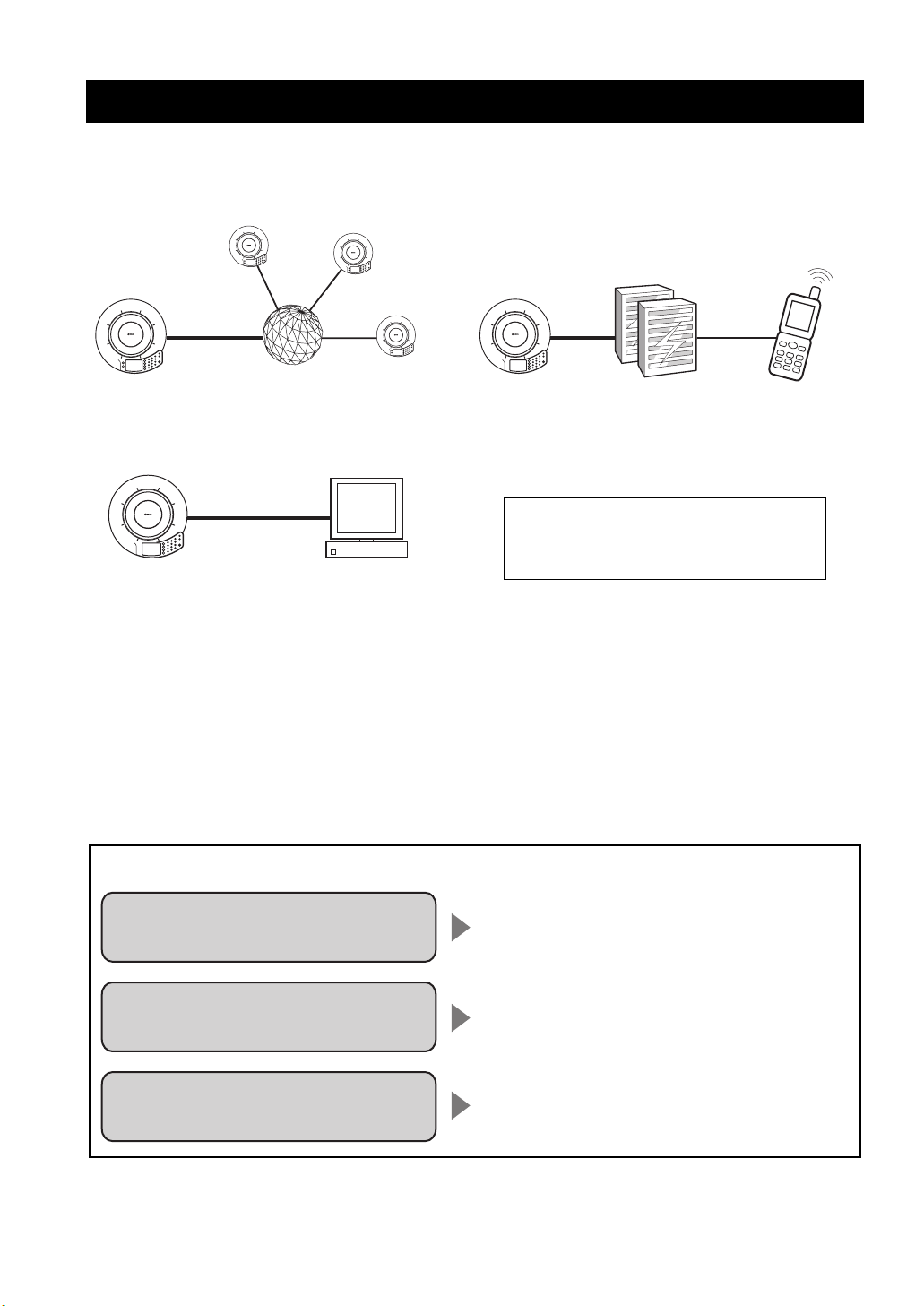
Features
This system is an audio conference system that connects IP networks including the Internet and corporate LAN as well as
analog telephone circuits to hold simultaneous communications between multiple persons in multiple locations.
Connection to IP network Communication through analog telephone circuit
Internet,
corporate LAN, etc.
Connection to external equipment
using an audio cable
This system is also capable of simultaneous
connections and communications across the IP
network, analog telephone circuits, and external
PC, TV conference system, etc.
equipment.
Voice conference through network/analog telephone circuits
This system can implement a voice conference between multiple locations and multiple persons when the systems in
different locations are connected to a network such as the Internet or corporate LAN or to analog telephone circuits.
When the system is connected to a PC through an audio cable, it can also be used as the microphone/speaker unit for a
web conference or software telephone.
Analog
telephone circuit
Landline telephone,
cellular phone, etc.
Voice conference that is “easy to talk” and “easy to hear”
The system employs arrayed microphones with high voice capturing capability and speakers with high voice
reproduction capability. In addition, it also incorporates a high-performance adaptive echo canceller to eliminate
interruptions of sound or drop in the voice level when multiple talkers speak simultaneously. These features make your
voice conference “easy to talk” and “easy to hear”.
For each application, see the following page.
Communication
through IP network
Communication
through telephone circuit
Use as a microphone/speaker unit
for a PC or TV conference system
Page 7 in the Basic Operation Guide
(a separate manual)
Page 14 in the Basic Operation Guide
(a separate manual)
Page 30
2
Page 8

About this Manual
• In this manual, the names of the following products are denoted as follows.
– Yamaha PJP-50R: this unit
– Microsoft
– Microsoft
– 10BASE-T (100BASE-TX) cable: LAN cable
• The IP addresses, domain names, and URL names mentioned in the setting examples are used merely for the purpose
of ease of explanation. When you perform the actual settings of this unit, be sure to set the addresses and names
according to the actual configuration of your network.
• Detailed knowledge on the Internet and network may be required to utilize this unit at its full performance. As the
provided manual does not give detailed technical information, please also refer to commercially available books as
required.
• This manual is printed prior to production. Design and specifications are subject to change in part as a result of
improvements, etc. If there are differences between the manual and the product, the product has priority.
®
Windows®: Windows
®
Windows XP®: Windows XP
■ Check the latest information
This manual has been compiled based on the latest version of the firmware as of October, 2007. Note that the actual
operations of the system may differ from the information given in this manual due to the addition of new functions or
improvement of existing functions as a result of upgrading of the firmware revision.
For the latest information and firmware, please visit the ProjectPhone support webpage of the following address. This
page also gives explanations on details of the latest functions.
http://www.yamaha.co.jp/english/product/projectphone/
For the revision upgrading procedure, refer to “Updating the Firmware” (page 34).
■ About trademarks
• Ethernet is a registered trademark of Xerox Corporation.
• Microsoft, Windows and Microsoft Excel are registered trademarks of Microsoft Corporation in United States and
other countries.
• Adobe and Acrobat are registered trademarks of Adobe Systems, Inc.
INTRODUCTION
Supplied Accessories
This product includes the following accessories. Before connecting this system, make sure you received all of the
following parts.
• AC adapter (PJP-PS01) x 1
• Power cable x 1
• LAN cable x 1
• Modular telephone cable x 1
• Owner’s Manual (Basic operation guide) x 1
• Owner’s Manual (Setup guide) x 1
• Warranty card x 1
English
3
Page 9

PREPARATION PROCEDURE
Preparation Procedure
The following preparation steps should be completed before using this unit.
Step 1: (page 5)
Connecting this unit to the network and turning
this unit on
ª
Step 2: (page 6)
Registering the network settings of this unit
• To perform communications through an IP network
such as a LAN, see “LAN: Acquiring the network
information from a DHCP server” (page 6) or “LAN:
Setting the network information manually” (page 6).
• For communication through the telephone circuit, see
“Telephone circuit: Setting the telephone circuit type”
(page 10).
ª
Step 3: (page 11)
Installing this unit in the conference room
■ To configure the settings from a PC
This section describes the preparation steps using the keys
on this unit, but the same settings are also available by
accessing the “Web Settings Page” from a PC. See
“Configuring the settings using the Web menu” (page 13).
Notes
• Some functions such as the address book cannot be set using the
keys on this unit alone.
• A connection through the IP network is required to access the
“Web Settings Page” of this system.
■ To use this unit with a SIP server
You must enter the settings by accessing the “Web
Settings Page” from a PC. See “Configuring the SIP server
setting” (page 15).
■ Notes on system connection
Please check the following before proceeding to
preparation.
LAN cable
(For use in the connection to a IP network)
• Prepare the supplied LAN cable.
• When using a commercially available LAN cable,
prepare a 10BASE-T or 100BASE-TX compatible
LAN cable.
Modular cable
(For use in the connection to a telephone
circuit)
• Prepare the supplied modular cable.
• When using a commercially available modular cable,
prepare a modular cable with RJ-11C 6P2C or 6P4C
plug.
Audio connection cable
(For use in the connection to a PC, etc.)
• Prepare a pair of commercially available audio
connection cables (stereo mini-jack cables).
• The designs of the line input/output terminals of TV
conference systems vary depending on the models.
Always use audio connection cables having the plugs
matching the line input/output terminals of the
connected TV conference system. Note that the plugs
connected to the ProjectPhone system of the audio
connection cables should always be the stereo miniplugs.
Caution regarding the connection to an IP
network
• When using this unit in the Internet, a global IP address
need to be obtained.
• When using this unit in a corporate LAN, it cannot be
connected to equipment outside the firewall. However,
as calls may become possible by changing the settings
of the router, please consult your network administrator
for details. This unit uses a port number of 5060 (UDP)
for SIP, and 57000 to 57010 (UDP) for RTP/RTCP.
• Obtain or decide the following information prior to the
installation of this unit.
– IP address and subnet mask settings of this unit
– IP addresses of the default gateway and DNS server
used by this unit
• To prevent the audio from being interrupted, it is
recommended that a network that can offer enough
transmission bandwidth is used. See “Specifications”
(page 46) for details.
• (For European customers only) Use the supplied LAN
cable to connect a network hub or router and this unit.
If you use a commercially available LAN cable, select
STP (Shielded Twisted Pair) cable.
Telephone system requirements
This system can be connected to the following type of
telephone system.
• Analog circuit (The system is incompatible with digital
circuits such as ISDN.)
• Telephone socket with an RJ-11C modular jack (if your
telephone socket is not equipped with an RJ-11C
modular jack, use a commercially available converter).
Telephone connection through a PBX
(Private Branch Exchange)
This system can be connected only to a 2-wire RJ-11 analog
PBX circuit. If you are unsure about your telephone circuit,
consult the manager in charge of the telephone circuit.
4
Page 10
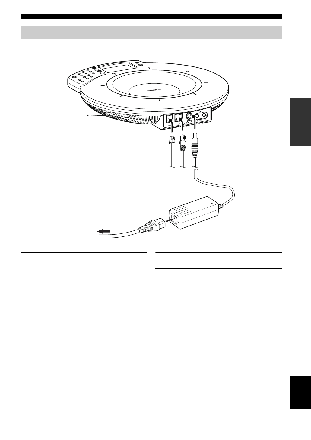
Step 1: Connecting this unit
Follow the procedure below to connect this unit to the network, and then connect the AC adapter.
12
Preparation Procedure
INSTALLATION
To an AC wall outlet
1 Connect the required communication cable.
• Connect the LAN cable between the LAN port of
the system and the network.
• Connect the modular cable between the LINE port
of the system and the telephone circuit.
2 Connect the AC adapter to the DC IN 12V
terminal.
3
3 Connect the power cable to the AC adapter.
4 Connect the power cable to the AC outlet.
This unit is turned on and the microphone indicators
light up in sequence.
English
5
Page 11
Preparation Procedure
Step 2: Registering the settings of this unit
Set up the system according to the network or telephone circuit to which the system is connected.
Communication through the Internet or LAN
The setup items are variable depending on whether or not the DHCP server is used.
When using the DHCP server:
See “LAN: Acquiring the network information from a DHCP server” (page 6).
When not using the DHCP server:
See “LAN: Setting the network information manually” (page 6).
Communication through the public switched telephone circuit
See “Telephone circuit: Setting the telephone circuit type” (page 10).
■ LAN: Acquiring the network information from a DHCP server
When this unit is used in a network containing a DHCP
server, no setting operation is required since the DHCP
server assigns all of the necessary network information
automatically.
To check if the correct network information
is obtained
Make sure that “Tel & IP ready” or “IP ready” is displayed
as shown below.
Tel & IP ready
(192.168.100.200)
2007.09.20 12:16:14
Menu :Address
y
If “IP ready” or “Tel & IP ready” is not displayed or
“???.???.???.???” is displayed, the network information has not
been ontained correctly.
■ LAN: Setting the network information manually
Follow the procedure below to register the network
information manually.
Note
Before setting the network information, check that this unit is
connected properly to the network. If the LED of the LAN port is
not lit, this system is not connected properly to the network.
y
The factory settings of the network information are as follows.
– IP address: 192.168.100.200
– Subnet mask: 255.255.255.0
– Default gateway: 0.0.0.0
– DNS server: 0.0.0.0
Numeric keys
/STANDBY
/
2
1
5
4
8
7
0
HOOK
/
VOL
3
6
MIC MUTE
9
#
6
Page 12
Preparation Procedure
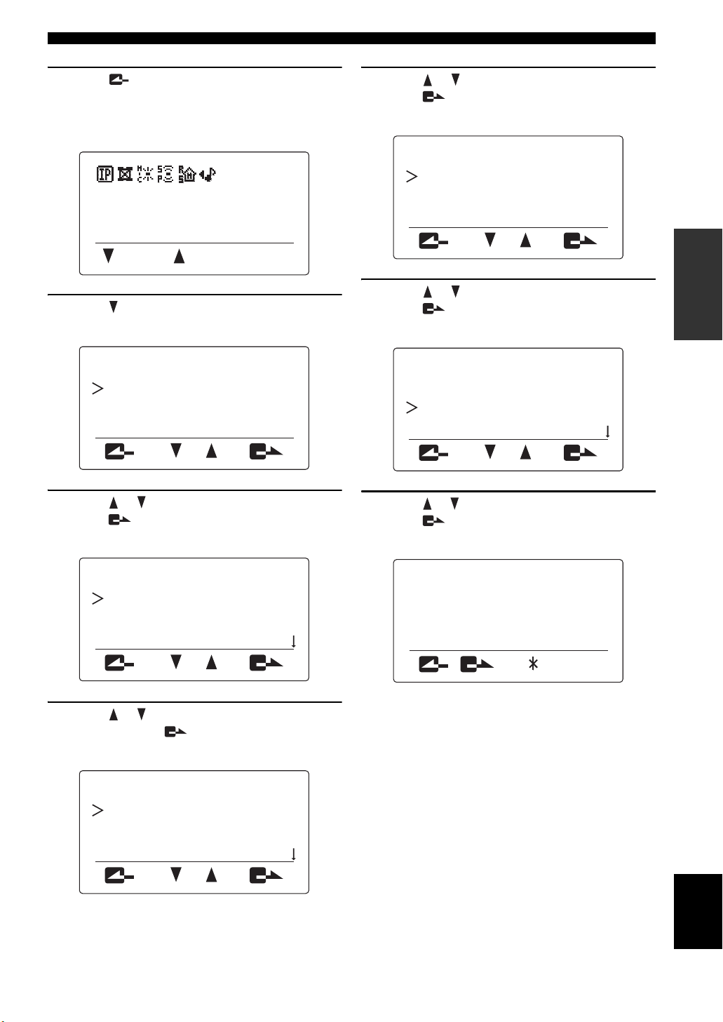
1 Press repeatedly until the initial display
appears.
If a DHCP server exist in the network, IP address
obtained from the server is displayed.
2007.09.20 12:16:14
Menu :Address
2 Press .
The menu screen appears.
Menu
1. Settings
2. Call History
3. Online
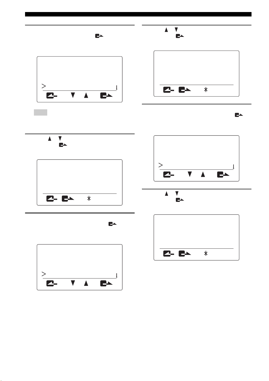
5 Press or to select “DHCP”, and then
press .
The “DHCP” menu appears.
DHCP
1. Enable
2. Disable
INSTALLATION
6 Press or to select “Disable”, and then
press .
The “Network Settings” menu reappears.
Network Settings
1. DHCP
2. IP Address
3. Subnet Mask
3 Press or to select “Settings”, and then
press .
The “Settings” menu appears.
Settings
1. Network Settings
2. Phone
3. Sound Settings
4 Press or to select “Network Settings”,
and then press .
The “Network Settings” menu appears.
Network Settings
1. DHCP
2. IP Address
3. Subnet Mask
7 Press or to select “IP Address”, and then
press .
The “IP Address” menu appears.
IP Address
192.168.100.200
^
(192.168.100.200)
[ ] [#]
English
7
Page 13
Preparation Procedure
8 Use the numeric keys to enter the IP address
of this unit, and then press .
The entered IP address is registered, and the
“Network Settings” menu reappears.
Network Settings
1. DHCP
2. IP Address
3. Subnet Mask
Note
Set an IP address that does not overlap with the IP address
of another piece of equipment connected to the LAN.
9 Press or to select “Subnet Mask”, and
then press .
The “Subnet Mask” menu appears.
Subnet Mask
255.255.255.000
^
11 Press or to select “Default Gateway”, and
then press .
The “Default Gateway” menu appears.
Default Gateway
000.000.000.000
^
(000.000.000.000)
[ ] [#]
12 Use the numeric keys to enter the “Default
Gateway” of this unit, and then press .
The entered “Default Gateway” is registered, and the
“Network Settings” menu reappears.
Network Settings
3. Subnet Mask
4. Default Gateway
5. DNS Server
(255.255.255.000)
[ ] [#]
10 Use the numeric keys to enter the subnet
mask of this unit, and then press .
The entered subnet mask is registered, and the
“Network Settings” menu reappears.
Network Settings
2. IP Address
3. Subnet Mask
4. Default Gateway
13 Press or to select “DNS Server”, and
then press .
The “DNS Server” menu appears.
DNS Server
000.000.000.000
^
(000.000.000.000)
[ ] [#]
8
Page 14
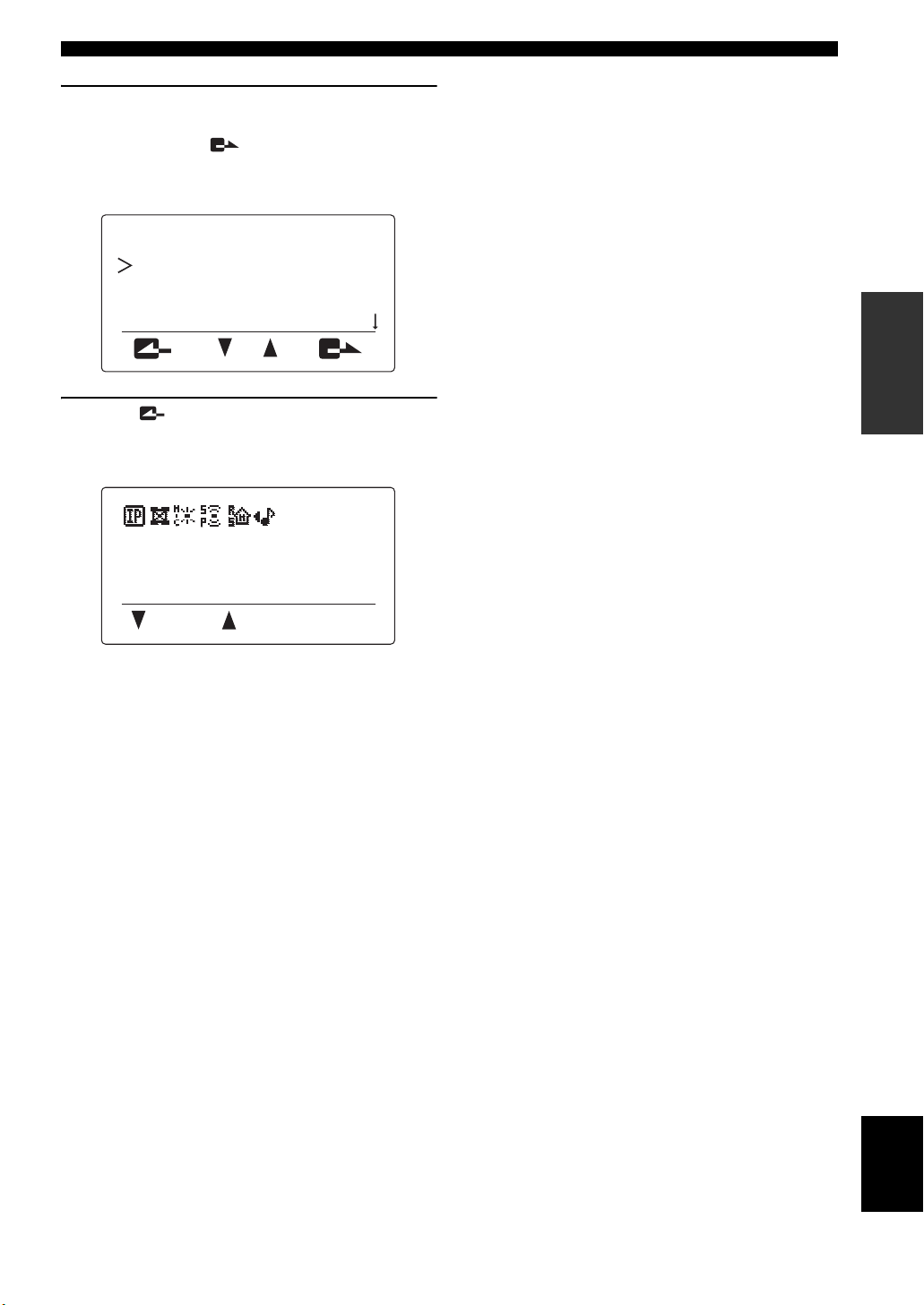
14 Use the numeric keys to enter the IP address
of the DNS server referenced by this unit,
and then press .
The entered DNS server IP address is registered, and
the “Network Settings” menu reappears.
Network Settings
1. DHCP
2. IP Address
3. Subnet Mask
15 Press repeatedly until the initial display
appears, and confirm that the IP address of
this system is displayed in it.
Tel & IP ready
(192.168.100.200)
2007.09.20 12:16:14
Menu :Address
Preparation Procedure
INSTALLATION
English
9
Page 15
Preparation Procedure
■ Telephone circuit: Setting the telephone circuit type
To have communications through the telephone circuit, it
is necessary to set the type of the connected telephone
circuit.
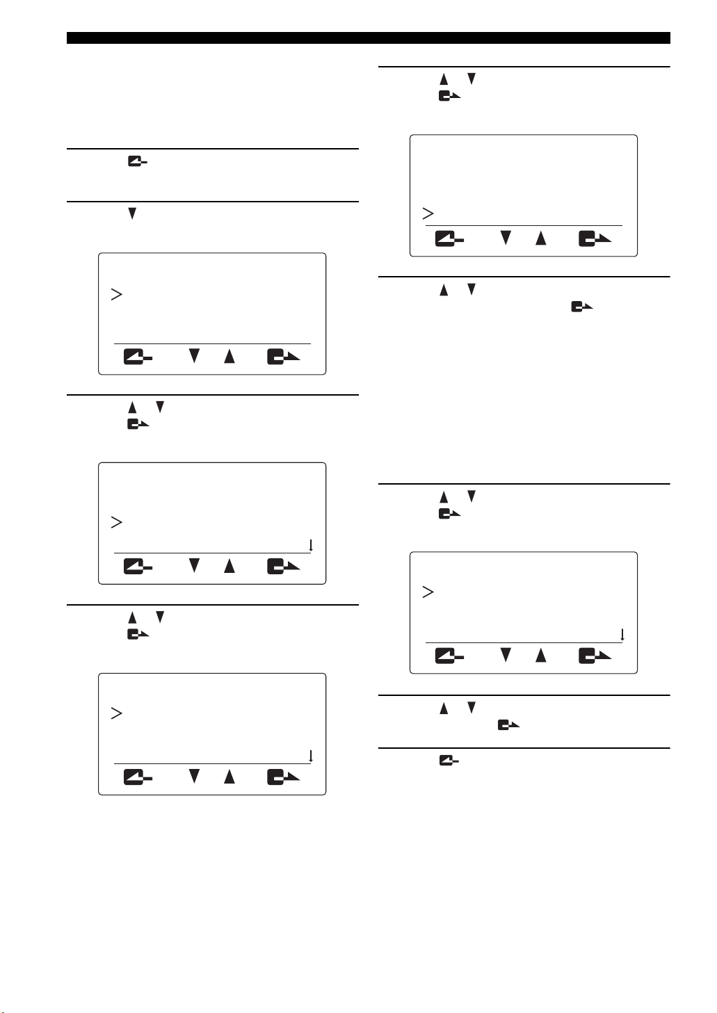
5 Press or to select “Dial Type”, and
press .
The “Dial Type” menu appears.
1 Press repeatedly until the initial display
appears.
2 Press .
The menu screen appears.
Menu
1. Settings
2. Call History
3. Online
3 Press or to select “Settings”, and then
press .
The “Settings” menu appears.
Settings
1. Network Settings
2. Phone
3. Sound Settings
Dial Type
1. 20PPS
2. 10PPS
3. Pb
6 Press or to select the type of your
telephone circuit, and press .
• 20PPS: Select when your telephone circuit is a
pulse (20 pps) line.
• 10PPS: Select when your telephone circuit is a
pulse (10 pps) line.
• Pb (Default): Select when your telephone circuit is
a tone line.
y
• In general, “20PPS” is applicable to most pulse lines.
• If you do not know the type of your telephone circuit,
consult your telephone company.
7 Press or to select “Country Code” and
press .
THe “Country Code” menu appears.
4 Press or to select “Phone”, and
press .
The “Phone” menu appears.
Phone
1. Dial Type
2. Hooking Time
3. Line Echo Cancel
Country Code
1. Canada
2. China
3. Germany
8 Press or to select the country use this
unit , and press .
9 Press repeatedly until the initial display
appears.
10
Page 16

Preparation Procedure
Step 3: Installing this unit in the conference room
After completing the settings, follow the procedure below to install this unit in the actual place, such as a conference
room.
■ About the installation environment
The speakers of this unit are on the bottom panel facing down. Place this unit horizontally on a desktop without placing
any object below this unit. If the system is unstable because the tabletop or desktop is not flat, adjust the height of the feet
using the adjusters provided at the bottom.
■ Position of the talkers
This unit is capable of 360° audio pickup when ZONE is set for the microphone mode. The pickup area depends on the
operation environment and settting. Refer to “Selecting the audio pickup area (microphone mode)” (page 16) for details.
INSTALLATION
VOL
3
2
6
1
MIC MUTE
5
9
4
8
#
7
0
/STANDBY
HOOK
11
English
Page 17

CONFIGURING THE SETTINGS
m
Configuring the Settings
You can configure the settings of this unit using the operation keys on this unit or a Web browser (Web menu) on the PC
connected to this unit.
Notes
• Some settings can be performed only by accessing the “Web Settings Page” for the system from the PC.
• For the configuration of the setup menus and the options for each setting item, see “Setting the Menu List” (page 14).
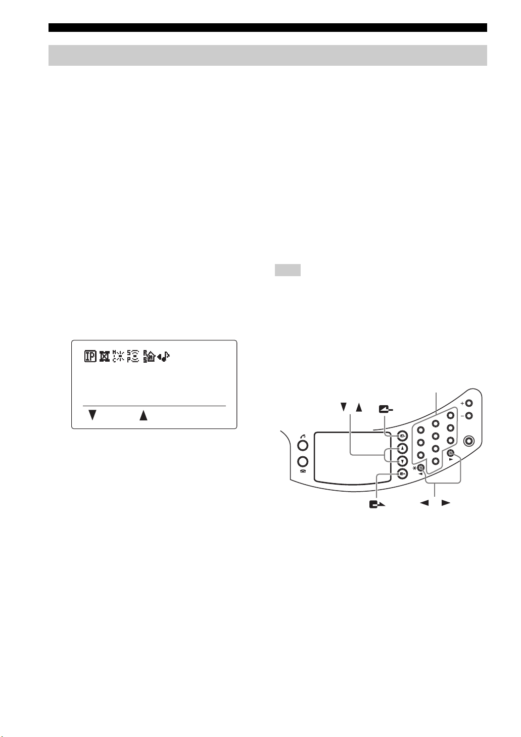
Configuring the settings using the keys on this unit
Follow the procedure below to configure the settings using
the operation keys on this unit.
VOL
3
6
MIC MUTE
9
#
/ STANDBY
/
2
1
5
4
8
7
0
HOOK
1 Press repeatedly until the initial display
appears.
2 Press .
The menu screen appears.
Menu
1. Settings
2. Call History
3. Online
4 Press or to select the menu category, and
then press .
The menu items in the selected category appear. The
following figure shows an example in which “1.
Network Settings” is selected. For details on the
setting menu configuration, see “Setting the Menu
List” (page 14).
Network Settings
1. DHCP
2. IP Address
3. Subnet Mask
5 Change the parameter.
The following figure shows an example in which “IP
Address” is selected. For details on parameters of
each menu item, see “Setting the Menu List”
(page 14).
IP Address
192.168.100.200
^
(192.168.100.200)
[ ] [#]
3 Press or to select “Settings”, and then
press .
The “Settings” menu appears.
Settings
1. Network Settings
2. Phone
3. Sound Settings
12
6 To confirm the setting, press .
The setting is saved in this unit.
■ To return to the previous menu without saving the setting
Press .
Page 18

Configuring the settings using the Web menu
Follow the procedure below to configure the settings using
the Web menu through a PC. This method is useful when
you configure several menu items.
Note
Microsoft Windows XP or Windows 2000 is required to view the
Web m e n u .
1 Check that this unit is turned on.
2 Start the Web browser. On the “File” menu,
choose “Open”.
Configuring the Settings
3 Enter “http://(IP address of this unit)”, and
then click “OK”.
The main window for the Web menu appears.
If the main window of the Web menu is not
displayed, see “Q2: Web menu setting is not
available” (page 39).
CONFIGURATIONS
13
English
Page 19

SETTING THE MENU LIST
Setting the Menu List
VOL
3
2
6
1
MIC MUTE
In the following description, indicates that the setting is possible using the keys on this unit and indicates that
it is possible using the Web menu through a PC.
Registering the IP network information
Register the settings for communication through the IP
network.
Note
These settings do not affect the communication through the
telephone circuit.
■ Configuring the DHCP server settings
VOL
3
2
6
1
MIC MUTE
5
9
4
8
7
0
Select “Enable” to assign the network information of this
unit using a DHCP server or “Disable” to assign the
network information manually. The default setting is
“Enable”.
Using the keys on this unit
In the initial display, select “Menu” → “Settings” →
“Network Settings” → “DHCP”.
Using the Web menu
In the Web menu, select “DHCP”.
■ Registering the IP address of this unit
VOL
3
2
6
1
MIC MUTE
5
9
4
8
7
0
The IP address of this unit must be registered when a
DHCP server is not used. The default setting is
“192.168.100.200”.
Note
If you want to specify the IP address of this unit manually while
this unit is connected to a LAN that has a DHCP server running,
set “DHCP” to “Disable”.
Using the keys on this unit
In the initial display, select “Menu” → “Settings” →
“Network Settings” → “IP Address”.
Using the Web menu
In the Web menu, select “IP Address”.
■ Registering the subnet mask
You can register the subnet mask. The default setting is
“255.255.255.0”.
Using the keys on this unit
In the initial display, select “Menu” → “Settings” →
“Network Settings” → “Subnet Mask”.
Using the Web menu
In the Web menu, select “Subnet Mask”.
5
9
4
8
7
0
Using the keys on this unit
In the initial display, select “Menu” → “Settings” →
“Network Settings” → “Default Gateway”.
Using the Web menu
In the Web menu, select “Default Gateway”.
■ Registering the DNS server referenced
VOL
3
2
6
1
MIC MUTE
by this unit
5
9
4
8
7
0
You can register the DNS server to be referenced by this
unit. The default setting is “0.0.0.0”.
Using the keys on this unit
In the initial display, select “Menu” → “Settings” →
“Network Settings” → “DNS Server”.
Using the Web menu
In the Web menu, select “DNS Server”.
■ Configuring the connection mode
VOL
3
2
6
1
MIC MUTE
5
9
4
8
7
0
You can select the mode used in connections involving
multiple locations. The default setting is “Mesh”.
• Mesh: This unit establishes a separate session with
each of the locations involved in the conference call.
This mode is indicated by on the display.
• Cascade Server: This unit functions as the server in
the cascade connection. This mode is indicated by
on the display.
• Cascade Client: This unit functions as a client in the
cascade connection. This mode is indicated by on
the display.
•Audio Device: This unit functions as the microphone /
speaker of the PC connected to this unit via a LAN. this
mode is indicated by on the display.
y
• For details on the mesh connection, see “Talking with Multiple
Locations” (page 12) in “Basic operation guide” (a separate
manual).
• For details on the cascade connection, see “Hierarchical
VOL
3
2
6
1
MIC MUTE
5
9
4
8
7
0
Connection of Multiple ProjectPhone (Cascade Connection)”
(page 26).
Using the keys on this unit
In the initial display, select “Menu” → “Settings” →
“Network Settings” → “Connection Mode”.
Using the Web menu
In the Web menu, select “Connection Mode”.
VOL
3
2
6
1
MIC MUTE
■ Registering the default gateway
5
9
4
8
7
0
You can register the default gateway. The default setting is
“0.0.0.0”.
14
Page 20

Tips for the “Audio Device” mode
This function can be used when this unit is connected to a PC
in the following conditions:
– When this unit and the PC are connected within the same
subnet.
Or,
– When this unit and the PC are connected directly by LAN
cable.
A special audio driver must be installed on the computer
before using “Audio Device” mode. The audio driver and
operating instructions can be downloaded from the following
URL:
http://www.yamaha.co.jp/english/product/projectphone/
download/appli/
See the above web site or the manual of the audio driver for
instructions on installing and operating the audio driver.
■ Configuring the SIP server setting
VOL
3
2
6
1
MIC MUTE
5
9
4
8
7
0
Select “Enable” to use the SIP server for the call. The
default setting is “Disable”. To use the SIP server, you
need to register the SIP server name and password using
the Web menu. See page 24 for details.
Notes
• Even if you select “Enable”, the SIP server is available for a call
only if the SIP server name and password are registered in the
Web menu.
• To connect a call using a SIP server, it is necessary to register
the SIP address of this unit. See page 24 for details.
Using the keys on this unit
In the initial display, select “Menu” → “Settings” →
“Network Settings” → “SIP Server”.
Using the Web menu
In the Web menu, select “SIP Server”.
■ Configuring the silence suppression
VOL
3
2
6
1
MIC MUTE
setting
5
9
4
8
7
0
You can suppress packet output when no sound is input at
the microphone of this unit.
Select “Enable” to activate this function. The default
setting is “Disable”.
Using the keys on this unit
In the initial display, select “Menu” → “Settings” →
“Network Settings” → “Silence Suppress”.
Using the Web menu
In the Web menu, select “Silence Suppression”.
Setup of telephone function
Register the settings for communication through the
telephone circuit.
Note
These settings do not affect the communication through the IP
network including the LAN.
Setting the Menu List
VOL
3
2
6
1
MIC MUTE
■
Setting the telephone circuit type
4
7
5
9
8
0
You can select the type of the connected telephone circuit.
• 20PPS: Select when your telephone circuit is a pulse
(20 pps) line.
• 10PPS: Select when your telephone circuit is a pulse
(10 pps) line.
• Pb (Default): Select when your telephone circuit is a
tone line.
y
If you do not know the type of your telephone circuit, consult
your telephone company.
Using the keys on this unit
In the initial display, select “Menu” → “Settings” →
“Phone” → “Dial Type”.
Using the Web menu
In the Web menu, select “Dial Type”.
■ Setting the hooking signal transmission
VOL
3
2
6
1
MIC MUTE
time
5
9
4
8
7
0
You can set the transmission time of the hooking signal for
use in a call transfer.
Using the keys on this unit
In the initial display, select “Menu” → “Settings” →
“Phone” → “Hooking Time”.
Using the Web menu
In the Web menu, select “Hooking Time”.
■ Setting the prefix
You can set the prefix that identifies the network. The
prefix can be used in call originations using the “telephone
number,” “SIP extension number” and “address book
number”.
Default settings:
• Phone Line: None
•IP Number: 8#
• Address Book: 9#
Using the Web menu
In the Web menu, select “Prefix”.
y
You can check the current prefix setteings by using the keys on
the unit. In the initial display, select “Menu”
“Phone” → “Prefix”. You cannot change the setting of the prefix
by using the keys on this unit
.
Notes
• Depending on the settings, you may not be able to call an
emergency number (such as that of the police or the fire
department). Also, note that there are cases where an
emergency number is accidentally called without your
intention.
• You cannot set the same prefix for different calling method.
→ “Settings” →
CONFIGURATIONS
English
15
Page 21

Setting the Menu List
■ Setting the country using the telephone
VOL
3
2
6
1
MIC MUTE
function
This function switches the detected telephone circuit
frequency according to the selection of the country where
this system is used. One of the following countries can be
selected.
• Canada
• China
• Europe 1
• Europe 2
Note
If you cannot make communication correctly through the
telephone circuit in Europe by setting “Country Code” to
“Europe1”, set “Country Code” to “Europe2”.
Using the keys on this unit
In the initial display, select “Menu” → “Settings” →
“Phone” → “Country Code”.
Using the Web menu
In the Web menu, select “Country Code”.
5
9
4
8
7
0
•Japan
• United Kingdom
• United States
•Other
Configuring the sound settings
■ Selecting the audio pickup area (microphone mode)
You can select the audio pickup area of the microphone
during a call.
• Zone (Default): Pick up the audio from a large area.
This mode is suitable for a relatively quiet
environment. This mode is indicated by on the
initial display.
VOL
3
2
6
1
MIC MUTE
5
9
4
8
#
7
0
/STANDBY
HOOK
■ Setting the telephone circuit mode for
VOL
3
2
6
1
MIC MUTE
Japan or China
You can select the telephone circuit mode when use this
unit in Japan or China.
In case “Country Code” is set to “Japan”:
•
Mode 1 (Default)
circumstances. The incoming call ringer does not ring when
this unit has received the CND (Caller Number Display) CID
(Caller ID) data from your telephone company.
Mode 2
•
: Use this mode if the extension telephones do not
respond properly to an incoming call in “Mode 1”. The
incoming call ringer rings when this unit has received the
CND (Caller Number Display) or CID (Caller ID) data from
your telephone company.
In case “Country Code” is set to “China”:
•
Mode 1 (Default)
switchboard used in locations other than Hong Kong and Macau.
• Mode 2: This mode is compatible with the switchboard
used in Hong Kong and Macau.
y
• When “Country Code” is set to a setting other than “Japan” and
“China”, the telephone circuit type settings do not affect the
functions of this unit.
• When you make changes to “Country Code”, “Line Mode”
automatically changes to “Mode 1”.
Using the keys on this unit
In the initial display, select “Menu” → “Settings”
→ “Phone” → “Line Mode”.
Using the Web menu
In the Web menu, select “Line Mode”.
: Use this mode under normal
: This mode is compatible with the
5
9
4
8
7
0
• Spot: Fix the audio pick up area to the front of the
microphone by narrowing the directivity. This mode is
suitable when the number of talkers is limited to one or
two, or when there is equipment that produces noise
such as a projector nearby.
To specify the audio pick up area, use the numeric keys
in the “Microphone Mode” menu. When a key is
pressed, the areas in the direction of the pressed key
and the opposite direction is enabled or disabled. The
following illustration shows the areas enabled by
pressing .
2
2
1
4
7
3
6
VOL
3
2
6
1
MIC MUTE
5
9
4
8
#
7
0
/STANDBY
HOOK
9
8
Microphone indicators (blue LED) of which direction
audio can be picked up from all light up. This mode is
indicated by on the initial display.
y
Each pair of areas should be positioned in opposite
directions (i.e. pairs of 1 and 9, 2 and 8, 3 and 7, and/or 4
and 6).
16
Page 22

Setting the Menu List
• Tracking: The microphone system automatically
tracks and focuses on the audio of the talker. The audio
can be picked up with narrow directivity so that other
noises can be reduced. This mode is suitable to pick up
the audio clearly in a noisy environment. The voice of
only one talker can be captured at a time.
Today...
VOL
3
2
6
1
MIC MUTE
5
9
4
8
#
7
0
Tracking the talker’s direction
automatically
VOL
3
2
6
1
MIC MUTE
5
9
4
8
#
7
0
Next...
In the “Microphone Mode” menu, press a numeric
key to specify the area in which tracking is disabled.
Every numeric key enables or disables the tracking in
the direction corresponding to the key as shown in the
following illustration.
2
1
3
Using the keys on this unit
In the initial display, select “Menu” → “Settings” →
“Sound Settings” → “Microphone Mode”.
y
You can display the “Microphone Mode” menu by holding down
in the initial display or calling display.
Using the Web menu
In the Web menu, select the “Microphone Mode”.
VOL
3
2
6
1
MIC MUTE
■ Configuring the speaker mode
You can select the audio output mode of the speakers
during a call.
• Mono: Even during a call with more than one location,
the audio from other units is not divided according to
their locations. This mode is indicated by on the
initial display.
• Multi (Default): When this unit is connected to
multiple locations, the audio from other units is
automatically divided according to their locations. This
mode is indicated by on the initial display.
The audio from each location is divided and output
from the left, center, or right side of the speaker if a
conference call involves 3 locations. If a conference
call involves 2 locations, the audio is output from the
left and right side of the speaker. The audio from the
destination of connection through the telephone circuit
is always output from the center position.
Using the keys on this unit
In the initial display, select “Menu” → “Settings” →
“Sound Settings” → “Speaker Mode”.
y
You can display the “Speaker Mode” menu by holding down
in the initial display or calling display.
Using the Web menu
In the Web menu, select “Speaker Mode”.
5
9
4
8
7
0
CONFIGURATIONS
4
1
4
7
/STANDBY
HOOK
7
6
VOL
3
2
6
MIC MUTE
5
9
8
#
0
9
8
All microphone indicators (blue LED) from the
direction which audio can be picked up light up. This
mode indicated by on the initial display.
y
5
• Press to pick up audio from all directions.
• You can select multiple areas at the same time.
English
17
Page 23

Setting the Menu List
Audio output in a call with a single location in
“Multi” speaker mode
If the “Speaker Mode” is set to “Multi” for a call with a
single location, the system creates a virtual sound source
for the talker according to the position of the talker in the
remote location as shown with the following illustrations.
Remote
Today...
1
4
7
location
VOL
3
2
6
MIC MUTE
5
9
8
#
0
This unit
VOL
3
2
6
1
MIC MUTE
5
9
4
8
#
7
0
Today...
Virtual sound
source
The virtual sound source for the remote talker is placed at
one of the positions according to the position of the talker
in the remote location as shown with the following
illustrations.
Remote
location
A
B
VOL
3
2
6
1
MIC MUTE
5
9
4
8
#
7
0
y
If the communication destination location is connected to another
location through a telephone circuit, the virtual audio source of
the latter location is created in the same position as the virtual
audio source of the talker in the former location.
VOL
3
2
6
1
MIC MUTE
■ Configuring the room size
5
9
4
8
7
0
You can configure this setting depending on the room size
and operating environment. However, you do not need to
change it from “Large” normally.
• Large (Default): Select this setting for using this unit
in an ordinary conference room, open space, or office.
The communication quality is most stable in this
setting. This setting is indicated by on the initial
display.
• Medium: Select this setting when this unit is used in a
room with large reverberations. This setting reduces
the echo heard at the other party locations using the
default “Large” setting. This setting is indicated by
on the initial display.
• Small: Select this setting when echo is still heard at the
other party locations using the “Medium” setting. This
setting is indicated by on the initial display.
Notes
• “Room Size” is a function for reducing the echo heard at the
other party locations. “Room Size” cannot reduce the echo that
is heard from this unit installed at the local location.
• “Medium” and “Small” can improve the echo processing
capability but lowers the communication quality. These settings
should be selected only when echo is heard at the other party
locations.
Using the keys on this unit
In the initial display or the display during communication,
select “Menu” → “Settings” → “Sound Settings” →
“Room Size”.
Using the Web menu
In the Web menu, select “Room Size”.
18
Position of the talker
Virtual sound
source
Virtual sound
source
C
C
VOL
3
2
6
1
MIC MUTE
5
9
4
8
#
7
0
This unit
AB
Virtual sound
source
Page 24

Setting the Menu List
■ Configuring the external input/output
VOL
3
2
6
1
MIC MUTE
setting
You need to configure this setting when you connect an
external audio equipment to this unit.
• None: Usually select this setting.
• Audio (Default): Select this setting when connecting
external audio equipment to this unit. This setting is
indicated on the initial display.
• Connection(mstr): Select this setting for the PJP-50R
to be used as the Master unit. This setting is indicated
on the initial display.
• Connection(slv): Select this setting for the PJP-50R to
be used as a Slave unit. This setting is indicated on
the initial display.
Using the keys on this unit
In the initial display, select “Menu” → “Settings” →
“Sound Settings” → “External I/O”.
Using the Web menu
In the Web menu, select “External Input/Output”.
y
• In an interlocked connection of the ProjectPhone systems, allow
a distance of at least 2 meters between them.
• Set the “Room Size” to “Small” for an interlocked connection.
• When connecting three ProjectPhone systems (Master, Slave 1
and Slave 2) in an interlocked connection, first connect the
AUDIO OUT terminal of the Master unit to the AUDIO IN
terminal of the Slave 1 unit. And then, connect the AUDIO
OUT terminal of the Slave 1 unit to the AUDIO IN terminal of
the Slave 2 unit. Finally, connect the AUDIO OUT terminal of
the Slave 2 unit to the AUDIO IN terminal of the Master unit.
See “Interlocked Connection of ProjectPhone Systems”
(page 29) for details.
■ Configuring the codec
At the beginning of communication, this system
negotiates with the remote communication terminal and
selects the optimum encoding method automatically
according to the encoding method usable by the remote
terminal.
This menu item is used to determine the range of encoding
methods that can be selected by this system.
For example, when this system wants to communicate
with an audio conference system other than the
ProjectPhone system and the system is not compatible
with the G.711 extended encoding method, select
“G.711”. If this is selected, this unit selects the optimum
encoding method from G.711 µ-law, G.711 A-law and
G.726-32 methods according to the compatibility of the
remote party.
• G.711 Extension (Default)
•G.711
•G.726-32
See “Specifications” (page 46) for details about the
frequency response and the transmission bandwidth for
each codec.
5
9
4
8
7
0
VOL
3
2
6
1
MIC MUTE
5
9
4
8
7
0
Using the keys on this unit
In the initial display, select “Menu” → “Settings” →
“Sound Settings” → “CODEC”.
Using the Web menu
In the Web menu, select “CODEC”.
VOL
3
2
6
1
MIC MUTE
■ Adjusting the volume
5
9
4
8
7
0
The audio input volume from the microphones and the
audio input/output volumes from/at the AUDIO IN/OUT
terminals can be adjusted.
• Microphone: Adjustment of the input volume from the
microphones of the system.
• Audio IN: Adjustment of the input volume from the
AUDIO IN terminal.
• Audio OUT: Adjustment of the output volume at the
AUDIO OUT terminal.
Using the keys on this unit
In the initial display, select “Menu” → “Settings” →
“Sound Settings” → “Volume Fine Adj”.
y
•Use and to adjust each volume and to confirm the
adjustment.
• Adjustment range: –12.0 dB to 12.0 dB (0.5 dB steps)
• Initial setting: 0 dB
Note
Varying the volume settings may distort audio in certain operating
environments. In this case, reduce the volume setting until the
distortion disappears.
VOL
3
2
6
1
MIC MUTE
■ Natural Voice Enhancer feature
5
9
4
8
7
0
Natural Voice Enhancer feature enhances the highfrequency fidelity of the audio signals input via telephone
circuit or IP network. This unit outputs the improved
sound from the speaker of this unit.
• Enable: Select to activate the Natural Voice Enhancer
mode.
• Disable (Default): Select to deactivate the Natural
Voice Enhancer mode.
Using the keys on this unit
In the initial display, select “Menu” → “Settings”
→ “Sound Settings” → “Voice Enhancer”.
Using the Web menu
In the Web menu, select “Natural Voice Enhancer”.
Note
■ This setting does not affect the audio signals input at the
AUDIO IN jack.
CONFIGURATIONS
English
19
Page 25

Setting the Menu List
Configuring the general settings
VOL
3
2
6
1
MIC MUTE
■ Adjusting the ring tone volume
You can adjust the ring tone volume by pressing VOL +/–.
Using the keys on this unit
In the initial display, select “Menu” → “Settings” →
“General Settings” → “Ring Volume”.
y
During the ringing volume setting, the ringing tone is generated
for use as the test tone. Pressing switches it to the ringing
tone for IP network calls, pressing switches it to that for
telephone calls, and pressing switches it to that for the
extension call using telephone circuit. The set volume is applied
commonly to the IP network and telephone ringing.
1
2
3
■ Controlling the system using the remote
VOL
3
2
6
1
MIC MUTE
operation function
5
9
4
8
7
0
This function is reserved for future extension.
Using the keys on this unit
In the initial display, select “Menu” → “Settings” →
“General Settings” → “Remote Control”.
■ Configuring the backlight off setting
VOL
3
2
6
1
MIC MUTE
5
9
4
8
7
0
Select the time until this unit turns off the backlight
automatically when it is not engaged in a call.
• Disable (Default): Select this setting to keep the
backlight on
• 3 minutes
• 5 minutes
• 10 minutes
• 30 minutes
Using the keys on this unit
In the initial display, select “Menu” → “Settings” →
“General Settings” → “BacklightOffTime”.
Using the Web menu
In the Web menu, select “Backlight OFF Time”.
■ Adjusting the LCD contrast
You can adjust the contrast of the display by pressing
VOL +/–
Using the keys on this unit
In the initial display, select “Menu” → “Settings” →
“General Settings” → “LCD Contrast”.
.
5
9
4
8
7
0
VOL
3
2
6
1
MIC MUTE
5
9
4
8
7
0
■ Selecting the menu language
VOL
3
2
6
1
MIC MUTE
(Language)
5
9
4
8
7
0
• English (Default): Select this setting to display the
menus in English.
• Japanese: Select this setting to display the menus in
Japanese.
• Chinese: Select this setting to display the menus in
Chinese.
Using the keys on this unit
In the initial display, select “Menu” → “Setup” →
“General Settings” → “Language”.
Using the Web menu
In the Web menu, select “Language”.
3
2
6
1
■ Setting the date and time manually
5
9
4
8
7
0
Set the time and date of the built-in clock of the system
manually. For details, see “Setting the Date and Time”
(page 22).
Using the keys on this unit
In the initial display, select “Menu” → “Setup” →
“General Settings” → “Time”.
■ Setting the time zone
Set the time zone of the region in which the system is
used. The time zone should be set in ±1-hour steps with
respect to the UTC (Coordinated Universal Time).
Using the Web menu
In the Web menu, select “Time”.
■ Setting the daylight saving time
If the region in which the system is used applies the
daylight saving time system, set this item to “ON”. This
item is usually set to “OFF”.
Using the Web menu
In the Web menu, select “Time”.
■ Selecting the SNTP server for synchronization
If you want to adjust the time automatically by
synchronizing this unit with an SNTP server, enter the
name or IP address of the desired SNTP server. See
“Setting the Date and Time” (page 22) for details.
Using the Web menu
In the Web menu, select “Time”.
■ Selecting the SNTP synchronization interval
If you want to adjust the time automatically by
synchronizing this unit with an SNTP server, specify the
synchronization interval in minutes. See “Setting the Date
and Time” (page 22) for details.
Using the Web menu
In the Web menu, select “Time”.
VOL
MIC MUTE
20
Page 26

Setting the Menu List
Call history management
■ Checking the communication history of this system
The communication history of this system can be viewed
on the Web setting page. This system stores the records of
up to 50 communications.
Displayed information:
• Time Of Day: Date and time at the start of each
communication.
• Communication Type: Means (telephone/IP network)
and type (incoming/outgoing/non-replied incoming/
multipoint) of communication are displayed. “Multi” is
displayed with automatic call origination/incoming
during mesh connection (page 14).
• Other Party: IP address, SIP address, IP intercom
number or telephone number of the other party of
communication. The name of the other party is also
displayed if it is registered in the address book.
Using the Web menu
In the Web menu, select “Call History”.
Notes
• To obtain correct time information, it is required to set the built-
in clock of the system in advance.
• With the communications through telephone circuit, the
incoming telephone number is displayed as “Caller ID
blocked”.
VOL
3
2
6
1
MIC MUTE
Setting the password
Use this feature to prevent important configurations from
being unwantedly changed by a user other than the
administrator.
5
9
4
8
7
0
■ Setting the password
Using the keys on this unit
In the initial display, select “Settings” → “General
Settings” → “Password” → “Set Password” and then enter
a 4-digit password by using the numeric keys.
If a password already exists, enter the current password in
“Old”. Enter a new password in “New” and then enter it
again in “Retype” for confirmation purpose.
Using the Web menu
In the Web menu, select “Set Password” and enter a 4digit password.
■ Deleting the password
Using the keys on this unit
In the initial display, select “Settings” → “General
Settings” → “Password” → “Delete Password” and then
enter a the current 4-digit password by using the numeric
keys.
The current password is deleted, and you can make
changes to the configurations previously under protection.
y
• When you set a password for the first time, leave “Old” empty.
• When a password has been set and you select a configuration
menu under protection by using the control keys of this unit, the
password entry screen appears. If you do not perform any
operations for the next 5 minutes, this unit returns to the
configuration protection mode.
• When a password has been set and you update the firmware of
this unit, you need to enter the current password.
• Once the existing password has been deleted, the configurations
previously under protection can no longer be protected. If you
want to protect the configurations again, perform the password
setting procedure again.
• If you forgot the password, you cannot initialize this unit to the
default factory settings. In this case, use the following master
password to set this unit to the default factory settings. The
master password can be entered in the Web menu.
Master Password
The master password for this unit is the serial number with
the second letter being omitted.
(e.g. If the serial number of this unit is “NP4012345”, the
master password is “N4012345” with “P” omitted.)
CONFIGURATIONS
The configuration parameters under protection are as
follows:
• Network Settings
• Phone
• Save Config
• Restore Settings
• Firmware Update
• Setting by using the Web menu
Calling a ProjectPhone system in
VOL
3
2
6
1
MIC MUTE
5
9
4
the same subnet
If the system is connected to an IP network such as LAN,
it can search and call another ProjectPhone system that is
available for communication in the same subnet.
Using the keys on this unit
From the initial display, select “Menu” → “Online” and
specify another system to be called.
8
7
0
21
English
Page 27

SETTING THE DATE AND TIME
Setting the Date and Time
VOL
3
2
6
1
MIC MUTE
5
9
4
Setting the date and time manually
1 Press repeatedly until the initial display
appears.
2 Press .
The menu is displayed.
3 Press or to select “Settings” and
press .
The Setup menu is displayed.
4 Press or to select “General Settings” and
press .
The “Environment Setup” menu appears.
5 Press or to select “Time” and
press .
The display for entering the current date and time
appears.
8
7
0
Setting the date and time using the SNTP server
The SNTP server (time distribution server) allows the
adjustment the date and time information in this unit
automatically at constant intervals.
Note
The synchronization with the SNTP server may not be available
depending on the security settings of the LAN accommodating
this unit. Using an external SNTP server requires the router
settings to be changed, etc. Refer to the instruction manuals for
your router for details.
1 In the Web menu, click “Time”.
The “Time” window appears.
6 Enter the current date and time using the
numeric keys, and press .
The entered date and time are entered, and
“Environment Setup” menu reappears.
y
The time zone and daylight saving time can also be set. See
page 20 for details.
2 In the “SNTP Server”, enter the name or IP
address of the SNTP server to be used.
3 In the “SNTP Synchronization Interval”,
select the desired interval for
synchronization with the SNTP server.
4 Click “Submit”.
The setting is registered and the top of the Web menu
reappears.
22
Page 28

Editing the Address Book
Frequently used addresses can be registered in the Address Book of each system.
Registering a new address
1 In the Web menu, click “View/Edit Address
Book”.
The “Address Book” window appears.
2 Click “edit” for the address you want to
register.
The “Edit Address” window appears.
5 Enter the address or phone number of the
destination to be registered.
Enter the address of the type selected in step 3.
6 Click “Submit”.
The new address is registered in the address book,
and the “Address Book” window reappears.
Notes
• Do not include the prefix to the IP address, telephone numbers,
etc. you want to enter.
• The Address Book can register up to 50 addresses of
communication destinations. The 50 addresses can include up
to 16 IP addresses and up to 16 SIP addresses.
• If the destination ProjectPhone unit obtains the IP address from
a DHCP server, its IP address may change from the last call.
If your call cannot reach the destination unit registered in the
address book, check the latest IP address configured at the
destination unit.
■ To abort the registration
Click “Reset” in step 4.
Editing an existing address
1 In the Web menu, click “View/Edit Address
Book”.
The “Address Book” window appears.
CONFIGURATIONS
3 Enter the name of the destination to be
registered in the “NAME” using up to 29
alphanumeric characters.
4 Select the type of the communication
destination information to be registered.
• SIP Address: Select for registering SIP addresses.
• Telephone: Select for registering public switched
telephone numbers.
• IP Number: Select for registering IP extension
numbers (page 25).
• IP Address: Select for registering IP addresses.
2 Click “edit” for the address you want to edit.
The “Edit Address” window appears.
3 Edit the information of the selected address,
and then click “Submit”.
The updated address is registered in the address book,
and the “Address Book” window reappears.
■ To delete the information a registered
communication destination
Click “del” in step 2.
English
23
Page 29

USING THE SIP SERVER
Using the SIP Server
Registering the SIP server information
If this unit is used in an environment with a SIP server, the
address of the SIP server to be referenced by this unit and
the SIP address of this unit should be registered. If
password authentication is required for accessing the
desired SIP server, it is also necessary to enter the
password. Consult your system administrator for details.
Note
The settings described in this section are not required if this unit
is used in an environment without a SIP server.
1 In the Web menu, click “SIP Server”.
The “SIP Server” window appears.
2 In the “SIP Server”, click “Enable”.
Notes on SIP server operation
• To connect a call using the SIP server, the SIP address
of this unit should be registered in the SIP server.
• It is not possible to establish a connection between a
ProjectPhone system that uses the SIP address and a
ProjectPhone system that uses the IP address.
• A global IP address should be assigned to the WAN on
the router side.
VOL
3
2
6
1
MIC MUTE
5
9
4
8
7
0
Branch A
Router
VOL
3
2
6
1
MIC MUTE
5
9
4
8
7
0
Headquarter
2
1
5
4
8
7
0
Router
SIP server
VOL
3
6
MIC MUTE
9
Branch B
Router
3 In the “SIP Server Name”, enter the name or
IP address of the SIP server.
4 If password authentication is required for
accessing the desired SIP server, enter the
authentication password for the SIP server in
the “SIP Server Password”.
5 In the “SIP Address”, enter the SIP address
to be set to this unit.
Enter the SIP address in the format
“sip:(sip address)”.
Example: sip:sipuser@yamaha.co.jp
6 Click “Submit”.
The setting is registered and the top window of the
Web menu reappears.
24
Page 30

■ Calling another unit by dialing the user ID
You can call the other party by dialing the user ID if it
consists of only the numbers.
Example:
SIP address of this unit is
SIP: 200@server1.net,
and the other party is SIP: 201@server1.net
You can call the other party by simply dialing “201”.
Using the SIP Server
Display in SIP server operation
Initial display
When you use the SIP server, IP address of this unit does
not appears in the initial display.
Lights up
when using the SIP server
Notes
• You can call only the destination which belongs to the same
domain as this unit.
• If you want to call another party which belongs to another
domain, register its SIP address in the address book beforehand
and call by using the address book.
• The prefix for the IP extension number is set to “8#” in the
initial setting. But it is also permitted to set a prefix. See
“Setting the prefix” (page 15) for details.
IP ready
2007.09.20 12:16:14
Menu :Address
“IP ready” or “Tel & IP ready” is displayed.
CONFIGURATIONS
Display during a call
The SIP addresses of this unit and other units are
displayed during the call.
osaka@sales.yamah...
nagoya@sales.yama...
tokyo@tech.yamaha...
Menu :Address
SIP address of the destination unit
Other displayed information and speaker modes are
identical to those in calls using the IP address. See page 7
in the “Basic Operation Guide” (a separate manual) for
details.
25
English
Page 31

HIERARCHICAL CONNECTION OF MULTIPLE PROJECTPHONE (CASCADE CONNECTION)
Hierarchical Connection of Multiple ProjectPhone
(Cascade Connection)
What is a cascade connection?
A cascade connection classifies the ProjectPhone to be
involved in a call into the servers and clients, connects
each client to a server and establishes the call by
interconnecting the servers. While the maximum number
of locations that can be connected in normal connection
mode (mesh mode) is four, a larger number of locations
can be connected by means of the cascade connection.
Example: Connecting the headquarter and branch A with a
2-location call and additionally connecting two divisions in two
different locations to each of the headquarter and branch A.
Cascade ClientCascade Client
VOL
3
2
6
1
MIC MUTE
5
9
4
8
7
0
Div. (a) Div. (b)
Cascade Server
VOL
3
2
6
1
MIC MUTE
5
9
4
8
7
0
Branch A
VOL
3
2
6
1
MIC MUTE
5
9
4
8
7
0
■ The maximum number of locations in a cascade connection
Up to eight locations can be connected by means of the
cascade connection. To establish the connection of eight
locations, you need to connect the servers and clients as
shown in the following figure.
Cascade ClientCascade Client
2
1
5
4
8
7
0
Cascade Server
Cascade Server
Cascade Server
VOL
3
6
MIC MUTE
9
Di v. Di v.
VOL
3
2
6
1
MIC MUTE
5
9
4
8
7
0
Branch
VOL
3
2
6
1
MIC MUTE
5
9
4
8
7
0
Branch
VOL
3
2
6
1
MIC MUTE
5
9
4
8
7
0
VOL
3
2
6
1
MIC MUTE
5
9
4
8
7
0
2
1
5
4
8
7
0
Cascade Client
VOL
3
6
MIC MUTE
9
Div.
Cascade Server
VOL
3
2
6
1
MIC MUTE
5
9
4
8
7
0
Headquarter
VOL
3
2
6
1
MIC MUTE
5
9
4
8
7
0
VOL
3
2
6
1
MIC MUTE
5
9
4
8
7
0
Div. (d)Div. (c)
Cascade ClientCascade Client
Note
To use the cascade connection, all of the ProjectPhone involved in
the call should be set to one of the cascade connection modes. A
unit set to the normal connection mode (mesh mode) cannot be
connected with a unit set to a cascade connection mode.
Headquarter
VOL
3
2
6
1
MIC MUTE
5
9
4
8
7
0
Div. Div.
Cascade ClientCascade Client
VOL
3
2
6
1
MIC MUTE
5
9
4
8
7
0
26
Page 32

Hierarchical Connection of Multiple ProjectPhone (Cascade Connection)
Configuring the cascade settings
First configure the setting of the cascade server unit, and
then configure the settings of the cascade client units.
■ Setup of the cascade server
1 Press repeatedly until the initial display
appears.
2 Press .
The menu screen appears.
Menu
1. Settings
2. Call History
3. Online
3 Press or to select “Settings”, and then
press .
The “Settings” menu appears.
5 Press or to select “Connection Mode”,
and then press .
The “Connection Mode” menu appears.
Connection Mode
1. Mesh
2. Cscd Server
3. Cscd Client
6 Press or to select “Cascade Server”, and
then press .
The settings are saved.
Return to the initial display and check that is
displayed at the top of the display.
■ Setup of the cascade clients
Follow the procedure in “Setup of the cascade server”
above and select “Cascade Client” in step 6.
After completing the setting, return to the initial display
and check that is displayed at the top of the display.
CONFIGURATIONS
Settings
1. Network Settings
2. Phone
3. Sound Settings
4 Press or to select “Network Settings”,
and then press .
The “Network Settings” menu appears.
Network Settings
4. Default Gateway
5. DNS Server
6. Connection Mode
English
27
Page 33

Hierarchical Connection of Multiple ProjectPhone (Cascade Connection)
Communication using a cascade connection
When the cascade connection is used, the calls can be
placed using the following procedure.
1 Call the master unit in another location from
the cascade master unit.
The calling method is the same as ordinary calling.
See page 7 in the “Basic operation guide” (a separate
manual) for details.
Cascade Server
(Slave)
Cascade Server
(Master)
Div. (a)
2
1
5
4
8
7
0
VOL
3
6
MIC MUTE
9
Branch
Cascade Server
(Slave)
Div. (b)
2 After the communication is established, call
each of the slave units connected to the
Cascade master unit.
The calling method is the same as ordinary calling.
VOL
MIC MUTE
Branch
VOL
MIC MUTE
Cascade Client
(Slave)
VOL
3
2
6
1
MIC MUTE
5
9
4
8
7
0
Cascade Client
(Slave)
2
1
5
4
8
7
0
Cascade Server
(Master)
Cascade Server
(Master)
VOL
3
6
MIC MUTE
9
Div. Div.
3
2
6
1
5
9
4
8
7
0
3
2
6
1
5
9
4
8
7
0
Headquarter
Cascade Server
(Master)
Cascade Server
(Slave)
VOL
3
2
6
1
MIC MUTE
5
9
4
8
7
0
Headquarter
Div. (d)Div. (c)
Cascade Server
(Slave)
VOL
3
2
6
1
MIC MUTE
5
9
4
8
7
0
VOL
3
2
6
1
MIC MUTE
5
9
4
8
7
0
Div. Div.
Cascade Client
(Slave)
Cascade Client
(Slave)
y
You can also call the slave units connected to the cascade
master unit before calling the master unit in another
location.
Display in cascade connection
The IP addresses of other units connected to this unit are
displayed during a call.
192.168.100.20
192.168.100.30
Menu :Address
IP address of other units
The mark displayed before each IP address indicates the
cascade connection mode of each unit.
• : “Cascade Server”.
• : “Cascade Client”.
28
Page 34

Interlocked Connection of ProjectPhone Systems
To have a meeting in a large conference room or with a large number of persons, some ProjectPhone systems can be
connected as slave units to this system. The number of connectable systems varies depending on the installation
environment.
y
• In an interlocked connection of the ProjectPhone systems, allow a distance of at least 2 meters between them.
• Set the “Room Size” to “Small” for an interlocked connection.
• If echo or howling is produced, install the ProjectPhone systems at larger distances or decrease their volumes.
• To avoid the echo or houling, set the volume level setting of each Project Phone system to the same level.
■ Connection
Using stereo mini-plug cables, connect the AUDIO OUT terminal of each ProjectPhone system to the AUDIO IN
terminal of another ProjectPhone system. The following illustration shows an example of an interlocked connection of
three ProjectPhone systems including this system.
Master unit (This system) Slave unit Slave unit
+
LINE LAN DC IN 12V IN AUDIO OUT
Connect the master
unit to the network
or an analog
telephone circuit.
■ Setup of the Master unit
Set “External Input/Output” to “Connection (Master)”.
The display shows .
Using the keys on this unit
In the initial display, select “Menu” → “Settings” →
“Sound Settings” → “External I/O” →
“Connection(mstr)”.
Using the Web menu
In the Web menu, select “External Input/Output” →
“Connection (Master)”.
+
LINE LAN DC IN 12V IN AUDIO OUT
+
LINE LAN DC IN 12V IN AUDIO OUT
■ Setup of the Slave units
Set “External Input/Output” to “Connection (Slave)”. The
display shows .
Using the keys on this unit
In the initial display, select “Menu” → “Settings” →
“Sound Settings” → “External I/O” → “Connection(slv)”.
Using the Web menu
In the Web menu, select “External Input/Output” →
“Connection (Slave)”.
CONFIGURATIONS
29
English
Page 35

CONNECTION USING AUDIO CONNECTION CABLES
Connection Using Audio Connection Cables
This system can be used as a high-performance, high-quality microphone/speaker unit when it is connected to a PC or
TV conference system with an audio cable.
Connecting with a PC or TV conference system
■ Connection
Prepare two commercially available audio connection cables (stereo mini-jack cables).
To audio input terminal
To audio output terminal
1 Connect the AUDIO IN jack of this unit to the
audio output terminal of the PC or Video
Conference system.
2 Connect the AUDIO OUT jack of this unit to
the audio input terminal of the PC or Video
Conference system.
■ Setup of this unit
Set “External Input/Output” to “Audio”. The display
shows .
Using the keys on this unit
In the initial display, select “Menu” → “Settings” →
“Sound Settings” → “External I/O” → “Audio”.
Using the Web menu
In the Web menu, select “External Input/Output” →
“Audio”.
y
• The audio may be distorted or too low in certain operating
environments. In such a case, adjust “Audio Input” and “Audio
Output” in the “Audio Fine Adjustment” menu. For details, see
page 19.
• Change the settings of the audio input/output of the connected
PC and TV conference system in advance. See “Setting of PC”
(page 32) for the settings of the audio input/output of PCs.
• The designs of the line input/output terminals of TV conference
systems vary depending on the models. Always use audio
connection cables having the plugs matching the line input/
output terminals of the connected TV conference system. Note
that the plugs connected to the ProjectPhone system of the
audio connection cables should always be the stereo mini-plugs.
30
Page 36

Connection Using Audio Connection Cables
Connection of the headphone output and microphone input terminals
If your PC or TV conference system does not have the line input/output terminals, it can be connected to this system
using the headphone output and microphone input terminals.
■ Connection
Prepare two commercially available audio connection cables (stereo mini-jack cables).
To microphone input terminal
1 Connect the AUDIO IN jack of this unit to the
headphone output terminal of the PC.
2 Connect the AUDIO OUT jack of this unit to
the microphone input terminal of the PC.
3 Set the “Audio Fine Adjustment” and
“External Input/Output” menus.
■ Setting the “Audio Fine Adjustment” menu
Set the “Audio Output” between –6.0 and –12.0 dB.
Using the keys on this unit
From the initial display, select “Menu” → “Settings” →
“Sound Settings” → “Volume Fine Adj” → “Audio
OUT”.
y
The audio Adjust the volume using and .
To headphone output terminal
CONFIGURATIONS
■ Setup of this unit
Set “External I/O” to “Audio”. The display shows .
Using the keys on this unit
From the initial display, select “Menu” → “Settings” →
“Sound Settings” → “External I/O” → “Audio”.
Using the Web menu
Open the “Web Settings Page” and select “External Input/
Output” → “Audio”.
y
• The audio may be distorted or too low in certain operating
environments. In such a case, adjust “Audio Input” and “Audio
Output” in the “Audio Fine Adjustment” menu. For details, see
page 19.
• Change the settings of the audio input/output of the connected
PC and TV conference system in advance. See “Setting of PC”
(page 32) for the settings of the audio input/output of PCs.
31
English
Page 37

Connection Using Audio Connection Cables
Setting of PC
The PC settings should be changed so that the audio input
from this unit to the PC is not output to this unit. It is
necessary to change the setup so that the audio input from
the connected terminal is accepted.
Note
The options of Sound and Audio Devices Properties may differ
depending on the PC. When different from the following
instruction, refer to the instruction manuals of your PC or the
sound card installed to your PC, and set the parameters as
follows.
1 Click “Start” on the task bar, point to
“Settings”, and click “Control Panel”.
2 Click “Sounds, Speech and Audio Devices”.
4 Click the “Audio” tab.
Click.
5 In the “Sound Playback” field, click
“Volume...”.
Click.
Click.
3 Click “Sounds and Audio Devices”.
Click.
6 In the “Line In” field, click “Mute” to check it.
Select either check box.
32
Page 38

7 In the “Sound recording” field, click
“Volume...”.
Click.
8 Select the input audio according to the
connection method.
Connection Using Audio Connection Cables
CONFIGURATIONS
Select either check box.
English
33
Page 39

UPDATING THE FIRMWARE
Updating the Firmware
You can download the firmware (program to control the functions of this unit) to use the latest features. There are two
ways to install the firmware. One way is to connect to the Internet using this unit and automatically install the latest
firmware. The other way is to download the firmware to your PC and install it manually (page 36).
Software Licensing Agreement
To use the revision upgrading function, you must accept the following software licensing agreement.
1 Permission of use
The present Software Licensing Agreement is intended to
allow Yamaha Corporation (hereinafter referred to as
“Yamaha”) to permit you to use the firmware (hereinafter
“this program”) for Yamaha IP audio conference system
(hereinafter “this product”). You can download this
program after having accepted the terms and conditions of
the present Software Licensing Agreement.
The present Software Licensing Agreement is applicable
to the downloaded copy of this program as well as to its
duplicates produced in accordance with the present
Software Licensing Agreement.
2 Inhibition of redistribution
You are permitted to download this program only for the
purpose of upgrading the functions of this product.
Uploading or posting this program at a website accessible
by the general public is prohibited unless you have
permission from Yamaha.
3 Production of duplicates
You may only duplicate this program for the purpose of
backup or when upgrading multiple units of this product.
4 Inhibition of decompiling, reverse
engineering or disassembling
You may not decompile, reverse-engineer, disassemble,
alter, permit the use of, distribute or create any derivative
works of this program.
5 Limitation of liabilities
Yamaha will not assume any liabilities on the damage to
the customers caused by the present Software Licensing
Agreement.
6 Export control
You shall comply with all applicable export laws and
regulations of any relevant countries including but not
limited to Japan and your country. You shall not, directly
or indirectly, export or re-export this program except in
compliance with such laws and regulations.
7 Compliance to laws and regulations
This Software Licensing Agreement should be compliant
to the laws and regulations of Japan and your country, and
should be interpreted in accordance with the laws of
Japan.
34
Page 40

Updating the Firmware
Updating the firmware automatically
Follow the procedure below to install the latest firmware
automatically.
Notes
• Automatic firmware update can be performed only if this unit is
connected to the Internet. If connection is not possible, follow
the procedure in “Updating the firmware manually” (page 36).
• Once the firmware update is started, do not perform any other
operation until the update operation is completed and this unit is
restarted. If the update operation is interrupted, this unit may
become unusable, in which case you need to return this unit to
the factory for repairs.
• When the firmware update is completed, this unit is restarted
automatically. All of the ongoing calls are disconnected at this
time.
• Do not unplug the power cable during the firmware update.
Otherwise, this unit could become unusable, in which case you
need to return this unit to the factory for repairs.
y
You can also specify the URL from which the firmware is
downloaded (page 36).
VOL
3
6
MIC MUTE
9
#
/ STANDBY
/
2
1
5
4
8
7
0
HOOK
4 Press , and then press or to select
“Firmware Update”.
Settings
5. Save/Load Config
6. Restore Settings
7. Firmware Update
5 Press .
The “Firmware Update” menu appears.
Firmware Update
ver. 1.30
1. Yes
2. No
6 Press or to select “Yes”, and then press
.
This unit connects to the Internet and downloads the
latest firmware. When downloading is completed, the
firmware update is automatically started.
CONFIGURATIONS
1 Press repeatedly until the initial display
appears.
2 Press .
The menu display appears.
3 Press or to select “Settings”, and then
press .
The “Settings” menu appears.
Settings
1. Network Settings
2. Phone
3. Sound Settings
■ To cancel the firmware downloading
In step 5, press .
It takes about a minute for the revision
updating operation.
MIC MUTE (orange LED) on the top panel of this unit
flashes during the firmware update process. Do not turn
this unit off while MIC MUTE (orange LED) is flashing.
English
35
Page 41

Updating the Firmware
When the firmware update is complete
This unit restarts automatically.
Check the version number in the “Program Version” on
the top of the Web menu to confirm that the new firmware
has been installed properly.
■ Specifying the URL from which to download the firmware
This feature is useful if you want to manage the firmware
version used by the ProjectPhones in your office.
1 Click “Firmware Update” in the Web menu.
The “Firmware Update” window appears.
Updating the firmware manually
If this unit cannot be connected to the Internet, you need to
download the latest firmware to your PC, and then install
it using TFTP.
■ Confirming the current version number
Check the “Program Version” on the top of the Web menu.
■ Downloading the latest firmware to your PC
Access the following ProjectPhone support page using
your PC and download the latest firmware.
2 Select “Other”, and then enter the URL to be
connected for updating the firmware.
3 Click “Submit”.
The URL that is connected when this unit carries out
the firmware update automatically is changed.
To use the latest firmware at all times
In step 2, select “YAMAHA Website”.
ProjectPhone website:
http://www.yamaha.co.jp/english/product/projectphone/
■ Installing the firmware to this unit
Follow the procedure below to install the firmware to this
unit.
1 Press repeatedly until the initial display
appears.
2 Start “Command Prompt” in the Windows PC
which can access the Web menu of this unit.
When using Windows XP, select the “Start” menu →
“All Program” → “Accessories” → “Command
Prompt”.
36
Page 42

3 Enter and run the following command.
tftp -i [IP address of this unit] put [file name of the
firmware]
Example:
tftp -i 192.168.100.200 put pjp50r_13.bin
y
Set the directory containing the firmware as the current
directory before executing the above command.
4 When the system shows the revision
upgrading confirmation message,
press .
The revision upgrading operation will start.
■ To cancel the firmware update
In step 4, press .
It takes about a minute for the revision
updating operation.
MIC MUTE (orange LED) on the top panel of this unit
flashes during the firmware update process. Do not turn
this unit off while MIC MUTE (orange LED) is flashing.
Updating the Firmware
When the firmware update is complete
This unit restarts automatically.
Check the version number in the “Program Version” on
the top of the Web menu to confirm that the new firmware
has been installed properly.
Notes
• Once the firmware update is started, do not perform any other
operation until the update operation is completed and this unit is
restarted. If the update operation is interrupted, this unit may
become unusable, in which case you need to return this unit to
the factory for repairs.
• When the firmware update is completed, this unit is restarted
automatically. All of the ongoing calls are disconnected at this
time.
• Do not unplug the power cable during the firmware update.
Otherwise, this unit could become unusable, in which case you
need to return this unit to the factory for repairs.
CONFIGURATIONS
37
English
Page 43

TROUBLESHOOTING
Troubleshooting
Refer to the following tables when this unit does not function properly. If the problem you are experiencing is not listed
or if the instruction does not help, contact your nearest authorized YAMAHA dealer or service center.
First, check if the microphone indicators light up. If the indicator is turned off, see “Q1: LED indicators do not light up”
below. For other cases, refer to one of the following pages according to the problem.
– “Q2: Web menu setting is not available” (pages 39)
– “Q3: A call cannot be made” (pages 40)
– “Q4: Other problems” (pages 41)
Q1: LED indicators do not light up
Problem Cause Remedy
The microphone indicators do not
light up.
This unit is not turned on. Check that the AC adapter and power cable
The power cable is not connected to the AC
outlet.
The main or branch circuit breaker is shut
off.
There is a power failure. Wait until the power supply is restored.
Power is not supplied to the AC outlet. If another electrical appliance also cannot be
The microphones are muted (the MIC MUTE
LED lights up).
are connected properly.
Check that the power cable is connected to
the AC outlet properly.
If the circuit breaker is tripped to “OFF”, set
it to “ON”.
If the circuit breaker is “ON”, set it to “OFF”
then “ON” again.
turned on, have the power outlet or power
wiring serviced.
If another electrical appliance can be turned
on, have this unit serviced.
Press MIC MUTE so that the MIC MUTE
LED is turned off.
38
Page 44

Q2: Web menu setting is not available
Problem Cause Remedy
The Web menu cannot be opened. The network setting of the PC is
The password for the Web menu is
entered but it cannot be opened.
The settings are returned to the
previous settings.
inappropriate (when other PCs and network
printers in the LAN are also unusable).
An inappropriate LAN cable is used for the
connection between this unit and the
network.
This unit is malfunctioning. Reset this unit to restore the factory settings
An inappropriate URL is specified. When using this unit for the first time or after
The Web browser of the PC is set to use a
proxy server.
A network fault occurred, or the
communication is blocked by a firewall.
The password is incorrect (when a password
error is displayed).
You did not click “Submit” or “Register” to
confirm the settings.
Troubleshooting
Set the LAN board and LAN card again and
reboot the PC.
Reset the IP address of the PC.
Use an optimum LAN cable (straight or cross
cable).
Use a LAN cable of Category 5 or higher.
(page 42), and then perform desired settings.
restoring the factory settings, access “http://
(IP address shown in the initial display of
this unit)”.
The Web menu cannot be opened when the
proxy setting is inappropriate.
When using Internet Explorer 6 for
Windows, open the “Tool” menu, select
“Internet Options” → “Connection” tab →
“Set LAN”, and clear the “Use proxy user”
check box.
Consult your network administrator to have
the network status checked.
Enter the master password (page 21)
After configuring the Web menu settings, be
sure to click “Submit” or “Register” to
confirm the changed settings. If the window
is closed without confirmation, the settings
you made are not saved.
INFORMATION
ADDITIONAL
39
English
Page 45

Troubleshooting
Q3: A call cannot be made
Problem Cause Remedy
A call cannot be originated. An inappropriate IP address is entered. Check the IP address of the other unit and
The IP address of the other unit has been
changed.
The communication is blocked by a firewall. Call by designating the IP address cannot
A network fault occurred. Wait until the fault is released.
The connection mode settings of this unit and
the other unit are different.
The IP/SIP settings of this unit and the other
unit are different.
The SIP address in the address book is
incorrect.
The SIP server is not running. Consult your system administrator.
The SIP address of the other unit is not
registered in the SIP server.
The Dial Type setup of this system differs
from the actual type of the telephone line.
This unit is connected to an incompatible
telephone circuit (digital circuit, etc.).
A call cannot be received. An incorrect IP address is entered on the
other unit.
The communication is blocked by a firewall. Call by designating the IP address cannot
A network fault occurred. Wait until the fault is released.
enter the correct IP address.
Check the IP address of the other unit and
enter the correct IP address.
cross a firewall. If you want to change the
calling method to SIP, consult your system
administrator.
Consult your system administrator.
A unit in the mesh connection mode cannot
communicate with a unit in a cascade
connection mode. Set the two units to the
same connection mode (page 14).
A unit using the SIP address cannot
communicate with a unit using the IP
address. Enable or disable the SIP server
operation as required so that both units use
the same type of address (page 15).
Register the correct SIP address (page 23).
Consult your system administrator.
Check the telephone line type and set the
Dial Type setup of this system accordingly.
Consult the manager of your telephone
circuit.
Enter the correct IP address on the other unit.
cross a firewall. If you want to change the
calling method to SIP, consult your system
administrator.
Consult your system administrator.
40
Page 46

Troubleshooting
Problem Cause Remedy
A call cannot be received. The connection mode settings of this unit and
The audio from the other unit cannot
be heard.
The audio is interrupted. The required bandwidth is not reserved. Check that the bandwidth required for
the other unit are different.
The IP/SIP settings of this unit and the other
unit are different.
The SIP server is not running. Consult your system administrator.
This unit is connected to an incompatible
telephone circuit (digital circuit, etc.).
The microphones are muted on the other
unit.
A network fault occurred. Wait until the fault is released.
The LAN cable or modular cable is not
connected properly.
The setting of the codec is not proper. Set the codec properly (page 19).
A unit in the mesh connection mode cannot
communicate with a unit in a cascade
connection mode. Set the two units to the
same connection mode (page 14).
A unit using the SIP address cannot
communicate with a unit using the IP
address. Enable or disable the SIP server
operation as required so that both units use
the same type of address (page 15).
Consult the manager of your telephone
circuit.
Cancel mute on the other unit.
communication is reserved (pages 4 and 46).
Consult your system administrator.
Check that the LAN cable or modular cable
is connected firmly.
Q4: Other problems
Problem Cause Remedy
The audio output is delayed. The required bandwidth is not reserved. Check that the bandwidth required for
This unit generates feedback noises. This unit is located against a wall. Locate this unit at a certain distance from a
An object is placed near this unit. Avoid placing an object in front of the
This unit is used in a room with high
reverberation.
I forgot the password. Enter the master password (page 21)
The clock setting has been cleared. The built-in battery for clock information is
dead.
communication is reserved (pages 4 and 46).
wall.
microphones.
Place objects with high sound absorbance in
the room by avoiding the positions in front of
the microphones.
Avoid talking with a loud voice to reduce
reverberations.
Change the Room Size setup (page 18).
Consult your nearest authorized Yamaha
dealer or service center.
INFORMATION
ADDITIONAL
English
41
Page 47

RESETTING THIS UNIT
Resetting this Unit
You can restore the factory settings of this unit.
Notes
Before restoring the factory settings, note the following.
• All of the settings that have default settings are set to the default
settings.
• Once the factory settings are restored, the previous settings
made by the user cannot be recalled.
■ Resetting using the keys on this unit
Follow the procedure below to restore the factory settings
using the keys on this unit.
VOL
3
6
MIC MUTE
9
#
/ STANDBY
/
2
1
5
4
8
7
0
HOOK
1 Press repeatedly until the initial display
appears.
2 Press .
The menu screen appears.
3 Press or to select “Settings”, and then
press .
The “Settings” menu appears.
Settings
1. Network Settings
2. Phone
3. Sound Settings
4 Press or to select “Restore Settings”.
Settings
4. General Settings
5. Save/Load Config
6. Restore Settings
y
If you forgot the password, enter the master password
(page 21).
5 Press .
The “Restore Settings” menu appears.
Restore Settings
1. Yes
2. Not Del AddrBook
3. No
6 Select “Yes” or “Leave Address Book” and
press .
The setups of the system are reset, and this unit
restarts automatically.
y
If you select “Leave Address Book”, the data in the Address
Book is retained.
■ To cancel resetting
In step 5, press , or press or to select “No” and
then press .
42
Page 48

■ Resetting using the Web menu
Follow the procedure below to restore the factory settings
using the Web menu.
1 In the Web menu, click “Restore Factory
Setting”.
The “Restore Factory Setting” window appears.
2 Click “Restore Factory Setting” or “Restore
Factory Settings without deleting an address
book”.
The setups of the system are reset, and this unit
restarts automatically.
y
If you select “Restore Factory Settings without deleting an
address book”, the data in the Address Book is retained.
Resetting this Unit
INFORMATION
ADDITIONAL
English
43
Page 49

OBTAINING THE SETTING INFORMATION FOR SUPPORT ON THIS UNIT
Obtaining the Setting Information for Support on this Unit
You can download the setting information and save them in your PC for reference when a problem occurs.
Note
These files are used for support and cannot be opened or edited using normal applications.
Obtaining the setting information
You can download the setting information of this unit and
save it in your PC.
1 Click “Download Setting Information” in the
Web menu.
The “Download File” window appears.
2 Click “Save”.
The “Save File” window appears.
3 Specify the file name and the place to be
saved, and then click “Save”.
The setting information is saved in your PC.
44
Page 50

Confirming the System Log Message of This Unit (Syslog)
You can send information or an event which occurs in the system of this unit to another unit as a message (this is called
“syslog”). “Syslog” contains information such as the start/shutdown of this unit, the login, the activity in normal states,
and the states of an error. You can specify the level of the message if necessary.
1 In the Web menu, click “Syslog Setting”.
The “Syslog” window appears.
2 Select the desired mode(s) which specifies
the kind of the message that is sent and
click.
y
You can select the check boxes of multiple modes.
• Debug Mode: Sends the debug log to confirm the
inner activity when an error occurs.
• Info Mode (Default): Sends the operation log such
as the event or states of the activity of this unit.
• Notice Mode: Sends the details of the operation
log when this unit is in the normal state.
3 In the “Syslog Network Output”, click
“Enable”.
4 In the “Syslog Host Address”, enter the host
IP address of the destination unit.
5 Click “Submit”.
The Syslog message specified in step 2 is sent to the
host address specified in step 4.
INFORMATION
ADDITIONAL
45
English
Page 51

SPECIFICATIONS
Specifications
General
• Dimensions (W x H x D) .............. 283 mm x 53.6 mm x 297.5 mm
• Weight (excl. AC adapter) ...................................................... 1.4 kg
• Power supply ....................................... 100 to 240 V AC (50/60 Hz)
• Power consumption ...................................................... Approx. 8 W
(11.1 in. x 2.1 in. x 11.7 in.)
(3.1 lbs)
Operating environment
• Ambient temperature ......................................................... 0 to 40°C
• Ambient humidity ............................20% to 85% (no condensation)
(32 to 104 °F)
Radio interference standard
............................................................................ FCC Part 15 (US)
EN55022 (EU)
LAN interfaces
• Ethernet ................................................... 10BASE-T/100BASE-TX
• Protocols ...................................................... IEEE802.3/IEEE802.3u
• Communication mode .................................. Auto negotiation, fixed
• Connectors ................................................................................RJ-45
• MAC address ...................................................Indicated on the label
• Polarity ................................... Straight/cross automatically detected
LINE interface
• Connector ................................................................................. RJ-11
Audio input/output interfaces
................................................. Stereo analog input/output (1 each)
• Connectors ........................................................................ Mini-jacks
Audio
• Arrayed microphones (directivity controlled)
• Zone audio pickup function
• Spot audio pickup function
• Microphone auto tracking function
Signal processing
• 3CH adaptive echo canceller
• Microphone/speaker array control
• Microphone gain control
Communications
• Connected locations
............................. Max. 4 locations, in the mesh connection mode
......................... Max. 8 locations, in the cascade connection mode
• Audio codec/frequency response (also refer to the table below)
..... G.711 extension original system (fs = 16 kHz)/300 Hz - 7 kHz
...................................................... G.711 (µ-law)/300 Hz - 3.4 kHz
..................................................... G.711 (A-law)/300 Hz - 3.4 kHz
.............................................................G.726-32/300 Hz - 3.4 kHz
• DHCP and SIP compliance
• Time synchronization using the SNTP server
• Port number for SIP ....................................................... 5060 (UDP)
• Port number for RTP/RTCP .........................57000 to 57010 (UDP)
Accessories
• AC adapter (PJP-PS01) x 1
• Power cable x 1
• LAN cable x 1
• Modular telephone cable x 1
• Owner’s manual <Setup Guide> (this manual) x 1
• Owner’s manual <Basic Operation Guide> x 1
• Warranty card x 1
Note
(For European customers only)
Use the supplied LAN cable to connect a network hub or router
and this unit. If you use a commercially available LAN cable,
select STP (Shielded Twisted Pair) cable.
Transmission bandwidth requirement of the system
Transmission bandwidth
(2-location call)
G.711 Extension
G. 7 1 1 µ- la w
/A-law
G.726-32 60 kbps for each of
160 kbps for each of
uplink and downlink
90 kbps for each of
uplink and downlink
uplink and downlink
Transmission bandwidth
320 kbps for each of
uplink and downlink
180 kbps for each of
uplink and downlink
46
*Specifications are subject to change without notice.
(3-location call)
——
Transmission bandwidth
(4-location call)
480 kbps for each of
uplink and downlink
270 kbps for each of
uplink and downlink
Page 52

Notes on Transferring/Disposing this Unit
The settings stored in this unit include personal information such as the address book or call history data. If this unit is
transferred or disposed without restoring the factory settings, information may be abused by a third party.
For instructions on how to restore the factory settings, see “Resetting this Unit” (page 42).
Note
When transferring this unit, be sure to include with the owner’s manual (this manual).
INFORMATION
ADDITIONAL
47
English
Page 53

©
This owner’s manual is based on the latest version of the firmware as
of October 2007. The functions and specifications could be possibly
added or changed by a firmware update.
Visit the PJP website to obtain the latest firmware and manuals.
PJP website:
http://www.yamaha.co.jp/english/product/projectphone/
Ce mode d’emploi se réfère à la toute dernière version du
micrologiciel, celle d’octobre 2007. Des fonctions et spécifications
peuvent être ajoutées ou changées par une mise à jour du
micrologiciel.
Consultez le site PJP pour obtenir les tout derniers micrologiciel et
manuels.
Site PJP:
http://www.yamaha.co.jp/english/product/projectphone/
Dieses Benutzerhandbuch basiert auf der neuesten Version der
Firmware vom Stand Oktober 2007. Die Funktionen und technischen
Daten können möglicherweise durch eine zukünftige FirmwareAktualisierung erweitert oder geändert werden.
Besuchen Sie die PJP-Website zum Erhalten der neuesten Firmware
und Anleitungen.
PJP-Website:
http://www.yamaha.co.jp/english/product/projectphone/
YAMAHA CORPORATION
10-1 Nakazawa-cho, Hamamatsu, Shizuoka 430-8650, Japan
2006 All rights reserved.
As of October, 2007
Printed in Japan
WK19730-2
 Loading...