

Page 1
Conference Microphone Speaker
UCGB
OWNER’S MANUAL
MODE D’EMPLOI
BEDIENUNGSANLEITUNG
Page 2
IMPORTANT SAFETY INSTRUCTIONS
IMPORTANT SAFETY INSTRUCTIONS
CAUTION
RISK OF ELECTRIC SHOCK
DO NOT OPEN
CAUTION: TO REDUCE THE RISK OF
ELECTRIC SHOCK, DO NOT REMOVE
COVER (OR BACK). NO USER-SERVICEABLE
PARTS INSIDE. REFER SERVICING TO
QUALIFIED SERVICE PERSONNEL.
• Explanation of Graphical Symbols
The lightning flash with arrowhead symbol, within an
equilateral triangle, is intended to alert you to the
presence of uninsulated “dangerous voltage” within
the product’s enclosure that may be of sufficient
magnitude to constitute a risk of electric shock to
persons.
The exclamation point within an equilateral triangle
is intended to alert you to the presence of important
operating and maintenance (servicing) instructions in
the literature accompanying the appliance.
1 Read Instructions – All the safety and operating instructions
should be read before the product is operated.
2 Retain Instructions – The safety and operating instructions
should be retained for future reference.
3 Heed Warnings – All warnings on the product and in the
operating instructions should be adhered to.
4 Follow Instructions – All operating and use instructions
should be followed.
5 Cleaning – Unplug this product from the wall outlet before
cleaning. Do not use liquid cleaners or aerosol cleaners.
6 Attachments – Do not use attachments not recommended by
the product manufacturer as they may cause hazards.
7 Water and Moisture – Do not use this product near water –
for example, near a bath tub, wash bowl, kitchen sink, or
laundry tub; in a wet basement; or near a swimming pool;
and the like.
8 Accessories – Do not place this product on an unstable cart,
stand, tripod, bracket, or table. The product may fall,
causing serious injury to a child or adult, and serious
damage to the product. Use only with a cart, stand, tripod,
bracket, or table recommended by the manufacturer, or sold
with the product. Any mounting of the product should
follow the manufacturer’s instructions, and should use a
mounting accessory recommended by the manufacturer.
9 A product and cart combination should be moved with care.
Quick stops, excessive force, and uneven surfaces may
cause the product and cart combination to
overturn.
10 Ventilation – Slots and openings in the cabinet are provided
for ventilation and to ensure reliable operation of the
product and to protect it from overheating, and these
openings must not be blocked or covered. The openings
should never be blocked by placing the product on a bed,
sofa, rug, or other similar surface. This product should not
be placed in a built-in installation such as a bookcase or rack
unless proper ventilation is provided or the manufacturer’s
instructions have been adhered to.
11 Power Sources – This product should be operated only from
the type of power source indicated on the marking label. If
you are not sure of the type of power supply to your home,
consult your product dealer or local power company. For
products intended to operate from battery power, or other
sources, refer to the operating instructions.
12 Grounding or Polarization – This product may be equipped
with a polarized alternating current line plug (a plug having
one blade wider than the other). This plug will fit into the
power outlet only one way. This is a safety feature. If you
are unable to insert the plug fully into the outlet, try
reversing the plug. If the plug should still fail to fit, contact
your electrician to replace your obsolete outlet. Do not
defeat the safety purpose of the polarized plug.
13 Power-Cord Protection – Power-supply cords should be
routed so that they are not likely to be walked on or pinched
by items placed upon or against them, paying particular
attention to cords at plugs, convenience receptacles, and the
point where they exit from the product.
14 Lightning – For added protection for this product during a
lightning storm, or when it is left unattended and unused for
long periods of time, unplug it from the wall outlet and
disconnect the antenna or cable system. This will prevent
damage to the product due to lightning and power-line
surges.
15 Power Lines – An outside antenna system should not be
located in the vicinity of overhead power lines or other
electric light or power circuits, or where it can fall into such
power lines or circuits. When installing an outside antenna
system, extreme care should be taken to keep from touching
such power lines or circuits as contact with them might be
fatal.
16 Overloading – Do not overload wall outlets, extension
cords, or integral convenience receptacles as this can result
in a risk of fire or electric shock.
17 Object and Liquid Entry – Never push objects of any kind
into this product through openings as they may touch
dangerous voltage points or short-out parts that could result
in a fire or electric shock. Never spill liquid of any kind on
the product.
18 Servicing – Do not attempt to service this product yourself
as opening or removing covers may expose you to
dangerous voltage or other hazards. Refer all servicing to
qualified service personnel.
19 Damage Requiring Service – Unplug this product from the
wall outlet and refer servicing to qualified service personnel
under the following conditions:
a) When the power-supply cord or plug is damaged,
b) If liquid has been spilled, or objects have fallen into the
product,
c) If the product has been exposed to rain or water,
i
Page 3

d) If the product does not operate normally by following
the operating instructions. Adjust only those controls
that are covered by the operating instructions as an
improper adjustment of other controls may result in
damage and will often require extensive work by a
qualified technician to restore the product to its normal
operation,
e) If the product has been dropped or damaged in any
way, and
f) When the product exhibits a distinct change in
performance - this indicates a need for service.
20 Replacement Parts – When replacement parts are required,
be sure the service technician has used replacement parts
specified by the manufacturer or have the same
characteristics as the original part. Unauthorized
substitutions may result in fire, electric shock, or other
hazards.
21 Safety Check – Upon completion of any service or repairs to
this product, ask the service technician to perform safety
checks to determine that the product is in proper operating
condition.
22 Wall or Ceiling Mounting – The unit should be mounted to a
wall or ceiling only as recommended by the manufacturer.
23 Heat – The product should be situated away from heat
sources such as radiators, heat registers, stoves, or other
products (including amplifiers) that produce heat.
IMPORTANT SAFETY INSTRUCTIONS
COMPLIANCE INFORMATION STATEMENT
(DECLARATION OF CONFORMITY PROCEDURE)
Responsible Party: Yamaha System Technology Inc.
Address: 100 Century Center Court
san Jose, California 95112
Telephone: (408)467-2300
FAX: (408)437-8791
Type of Equipment: Conference Microphone Speaker
Model Name: PJP-100UH
This device complies with Part 15 of the FCC Rules.
Operation is subject to the following two conditions:
1) this device may not cause harmful interference, and
2) this device must accept any interference received
including interference that may cause undesired operation.
See user manual instructions if interference to radio
reception is suspected.
FCC INFORMATION (for US customers)
1 IMPORTANT NOTICE: DO NOT MODIFY THIS
UNIT!
This product, when installed as indicated in the
instructions contained in this manual, meets FCC
requirements. Modifications not expressly approved by
Yamaha may void your authority, granted by the FCC, to
use the product.
2 IMPORTANT: When connecting this product to
accessories and/or another product use only high quality
shielded cables. Cable/s supplied with this product MUST
be used. Follow all installation instructions. Failure to
follow instructions could void your FCC authorization to
use this product in the USA.
3 NOTE: This product has been tested and found to comply
with the requirements listed in FCC Regulations, Part 15
for Class “A” digital devices. Compliance with these
requirements provides a reasonable level of assurance that
your use of this product in a commercial environment will
not result in harmful interference with other electronic
devices. However, operation of this product in a residential
area is likely to cause interference in some form. In this
case you, the user, bear the responsibility of correcting this
condition.
This product generates/uses radio frequencies and, if not
installed and used according to the instructions found in
the users manual, may cause interference harmful to the
operation of other electronic devices.
Compliance with FCC regulations does not guarantee that
interference will not occur in all installations. If this
product is found to be the source of interference, which
can be determined by turning the product “OFF” and
“ON”, please try to eliminate the problem by using one of
the following measures:
Relocate either the product generating the interference or
the device that is being affected by the interference.
Utilize power outlets that are on different branch (circuit
breaker of fuse) circuits or install AC line filter/s.
In the case of radio or TV interference, relocate/reorient
the antenna. If the antenna lead-in is 300 ohm ribbon lead,
change the lead-in to coaxial type cable.
If these corrective measures do not produce satisfactory
results, please contact your local retailer authorized to
distribute this type of product. If you can not locate the
appropriate retailer, please contact Yamaha Electronics
Corp., U.S.A. 6660 Orangethorpe Ave, Buena Park, CA
90620.
The above statements apply ONLY to those products
distributed by Yamaha Corporation of America or its
subsidiaries.
ii
Page 4

CAUTION: READ THIS BEFORE OPERATING YOUR UNIT.
1 To assure the finest performance, please read this manual
carefully. Keep it in a safe place for future reference.
2 Install this unit in a well ventilated, cool, dry, clean place with at
least 10 cm on the top, 10 cm on the left and right, and 10 cm at
the back of this unit — away from direct sunlight, heat sources,
vibration, dust, moisture, and/or cold.
3 Locate this unit away from other electrical appliances, motors, or
transformers to avoid humming sounds.
4 Do not expose this unit to sudden temperature changes from cold
to hot, and do not locate this unit in an environment with high
humidity (i.e. a room with a humidifier) to prevent condensation
inside this unit, which may cause an electrical shock, fire,
damage to this unit, and/or personal injury.
5 Avoid installing this unit where foreign object may fall onto this
unit and/or this unit may be exposed to liquid dripping or
splashing. On the top of this unit, do not place:
– Other components, as they may cause damage and/or
discoloration on the surface of this unit.
– Burning objects (i.e. candles), as they may cause fire, damage
to this unit, and/or personal injury.
– Containers with liquid in them, as they may fall and liquid
may cause electrical shock to the user and/or damage to this
unit.
6 Do not cover this unit with a newspaper, tablecloth, curtain, etc.
in order not to obstruct heat radiation. If the temperature inside
this unit rises, it may cause fire, damage to this unit, and/or
personal injury.
7 Do not plug in this unit to a wall outlet until all connections are
complete.
8 Do not operate this unit upside-down. It may overheat, possibly
causing damage.
9 Do not use force on switches, knobs and/or cords.
10 When disconnecting the power cable from the wall outlet, grasp
the plug; do not pull the cable.
11 Do not clean this unit with chemical solvents; this might damage
the finish. Use a clean, dry cloth.
12 Only voltage specified on this unit must be used. Using this unit
with a higher voltage than specified is dangerous and may cause
fire, damage to this unit, and/or personal injury. YAMAHA will
not be held responsible for any damage resulting from use of this
unit with a voltage other than specified.
13 Do not attempt to modify or fix this unit. Contact qualified
YAMAHA service personnel when any service is needed.
The cabinet should never be opened for any reasons.
14 When not planning to use this unit for long periods of time (i.e.
vacation), disconnect the AC power plug from the wall outlet.
15 Be sure to read the “Troubleshooting” section on common
operating errors before concluding that this unit is faulty.
16 Before moving this unit, press and hold MIC MUTE for 3
seconds to set this unit in standby mode, and disconnect the AC
power plug from the wall outlet.
17 Condensation will form when the surrounding temperature
changes suddenly. Disconnect the power cable from the outlet,
then leave the unit alone.
18 When using the unit for a long time, the unit may become warm.
Turn the power off, then leave the unit alone for cooling.
19 Install this unit near the wall outlet and where the AC power plug
can be reached easily.
This unit is not disconnected from the AC power source as
long as it is connected to the AC wall outlet, even if this unit
itself is turned off. This state is called the standby mode. In
this state, this unit is designed to consume a very small quantity of power.
FOR CANADIAN CUSTOMERS
To prevent electric shock, match wide blade of plug to wide
slot and fully insert.
This Class A digital apparatus complies with Canadian
ICES-003.
WARNING
TO REDUCE THE RISK OF FIRE OR ELECTRIC SHOCK,
DO NOT EXPOSE THIS UNIT TO RAIN OR
MOISTURE.
WARNING
THE POWER SUPPLY CABLE OF THIS UNIT MUST BE
CONNECTED TO THE MAIN SOCKET OUTLET VIA A
PROTECTIVE EARTHING CONNECTION.
■ For U.K. customers
If the socket outlets in the home are not suitable for the plug
supplied with this appliance, it should be cut off and an
appropriate 3 pin plug fitted. For details, refer to the instructions
described below.
Note
The plug severed from the mains lead must be destroyed, as a
plug with bared flexible cord is hazardous if engaged in a live
socket outlet.
■ Special Instructions for U.K. Model
WARNING-THIS APPARATUS MUST BE
EARTHED.
IMPORTANT
THE WIRES IN THIS MAINS LEAD ARE COLOURED
IN ACCORDANCE WITH THE FOLLOWING CODE:
GREEN-AND-YELLOW:EARTH
BLUE:NEUTRAL
BROWN:LIVE
As the colours of the wires in the mains lead of this apparatus may not correspond with the coloured markings
identifying the terminals in your plug, proceed as follows:
The wire which is coloured GREEN-AND-YELLOW
must be connected to the terminal in the plug which is
marked by the letter E or by the safety earth symbol or
coloured GREEN or GREEN-and-YELLOW.
The wire which is coloured BLUE must be connected to
the terminal which is marked with the letter N or coloured
BLACK.
The wire which is coloured BROWN must be connected to
the terminal which is marked with the letter L or coloured
RED.
iii
Page 5

INTRODUCTION
FEATURES ............................................................ 2
SUPPLIED ACCESSORIES ................................ 3
CONTROLS AND FUNCTIONS ........................ 4
PREPARATION
PREPARATION PROCEDURE ......................... 7
Step 1: Connecting this unit....................................... 8
Step 2: Changing the settings of PC .......................... 9
Step 3: Installing this unit in the conference room .. 11
CONFIGURATIONS
CONNECTION USING AUDIO
CONNECTION CABLES ............................... 12
Connecting audio connection cables ....................... 12
Changing the settings of PC .................................... 13
Connection of two units........................................... 14
CONFIGURING SETTINGS ............................. 15
SETTING MENU LIST ...................................... 16
Configuring sound settings ...................................... 16
Configuring general setting ..................................... 18
Restoring the factory settings .................................. 18
UPDATING THE FIRMWARE ........................ 19
Software Licensing Agreement ............................... 19
Updating the firmware manually ............................. 20
CONTENTS
PREPARATIONINTRODUCTION
CONFIGURATIONS
INFORMATION
ADDITIONAL
ADDITIONAL INFORMATION
TROUBLESHOOTING ...................................... 21
Q1: LED indicators do not light up ......................... 21
Q2: A problem in the communication audio ........... 22
RESETTING THE UNIT ................................... 23
SPECIFICATIONS ............................................. 24
NOTES FOR TRANSFER/DISPOSAL
OF THIS UNIT ................................................ 24
English
1
Page 6
FEATURES
FEATURES
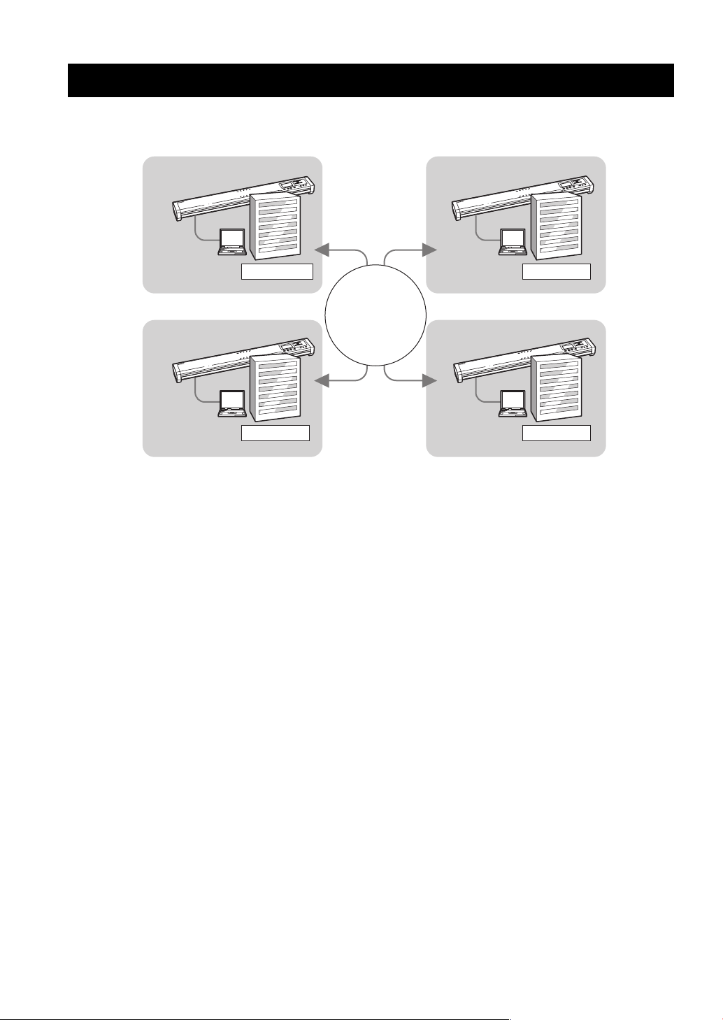
This product is a microphone/speaker unit to be connected to a Video or Web Conference system for use as its audio
terminal.
Headquarter
Network, such as
Internet,
Corporate LAN,
etc.
Branch A
Branch B
Branch C
Connection to a Video or Web Conference system
This unit can be connected to a Video or Web Conference system for use as the microphone/speaker unit of the system.
Replacing the audio input/output of the system with this unit provides conferences for everyone in various locations, all
at the same time, in a cost-effective manner.
Arrayed microphones and speakers for high audio quality
Depending on the using environment, the microphones can control the audio pickup area so that the clear conversation is
assured. Also, the directivity of the speakers is controlled so that clear audio can be transmitted to the participants sitting
in the optimum area even when the volume level is low.
2
Page 7

SUPPLIED ACCESSORIES
■ About this manual
• In this manual, the names of the following products are described as follows.
– Yamaha PJP-100UH: this unit
– Yamaha Conference Microphone Speaker: PJP
– Microsoft
– Microsoft
– Microsoft
• Details knowledge on the PC, Internet and network may be required to utilize this unit at its full performance. As the
provided manual does not give detailed technical information, please also refer to commercially available books as
required.
• This manual is printed prior to production. Design and specifications are subject to change in part as a result of
improvements, etc. In case of differences between the manual and the product, the product has priority.
®
Windows®: Windows
®
Windows XP®: Windows XP
®
Windows 2000® Professional: Windows 2000 Professional
■ About trademarks
• Microsoft and Windows are registered trademarks of Microsoft Corporation in the United States and other countries.
• Intel and Celeron are trademarks or registered trademarks of Intel Corporation and its subsidiaries in the United States
and other countries.
SUPPLIED ACCESSORIES
This product includes the following accessories. Before connecting this system, make sure you received all of the
following parts.
• AC adapter (PJP-PS01) x 1
• Power cable x 1
• USB cable x 1
• Pad x 3
• Owner’s Manual (This manual) x 1
• Warranty card x 1
INTRODUCTION
English
3
Page 8
CONTROLS AND FUNCTIONS
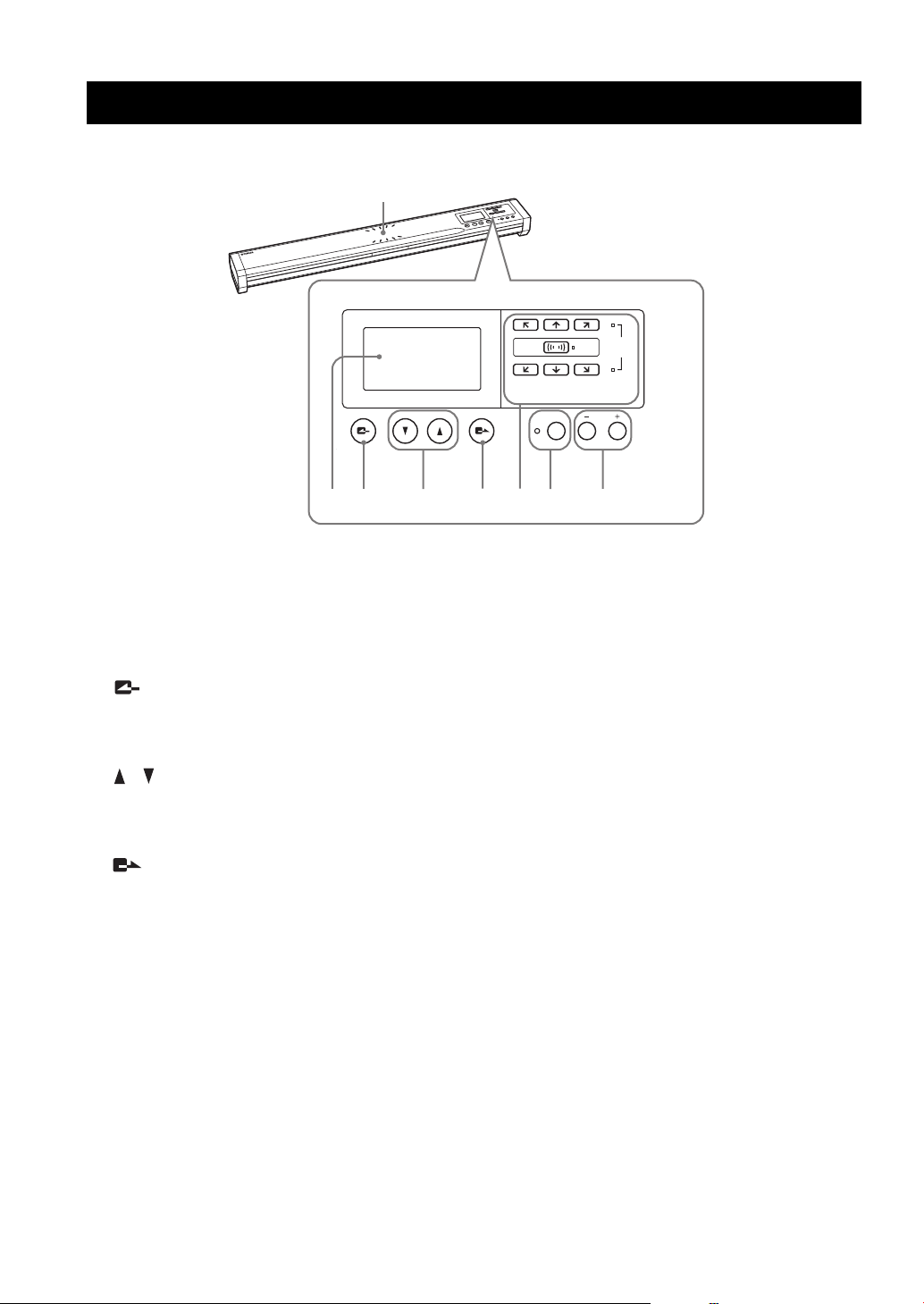
■ Top panel
CONTROLS AND FUNCTIONS
MIC/SPALL
MIC/SP AREA SELECT
MIC MUTE VOL
23145678
1 Microphone indicators
A blue LED lights to indicate the audio pick up area.
2 Display
The LCD shows the current status of this unit (page 6).
3 (Cancel)
Press the key to cancel a setting without saving it or to
return to the previous page.
4 / (Up/Down)
Press either key to select a setting item or move the cursor
up or down.
5 (Enter)
Press the key to enter a setting.
6 Area select keys
Press one of the keys to select an audio pickup area in the
microphone mode setting (page 16).
7 MIC MUTE
Press the key to temporarily defeat (mute) the
microphones of this unit. The LED to the left of the key
lights in red during muting.
Pressing the key again during muting cancels it and turns
the LED off.
y
Pressing and holding MIC MUTE for 3 seconds sets this unit to
the standby mode. When this unit is in the standby mode, it can be
turned on again by pressing any key.
8 VOL +/–
Press either key to adjust the speaker volume. Holding
either key increases or decreases the volume continuously.
4
Page 9
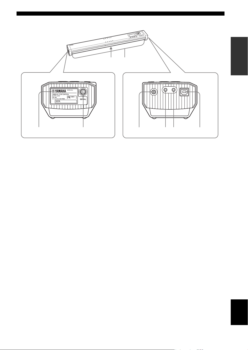
■ Other
CONTROLS AND FUNCTIONS
INTRODUCTION
43
PJP-100UH
PJP-100UH
21
1 Label
The label carries the following information.
• MODEL No.: Model number of this unit.
• SER.: Serial number for use in management/
distinction of this unit.
2 SERIAL terminal
Reserved for future extension.
3 Arrayed speakers (Bottom panel)
Twelve speakers are arrayed on the bottom panel for use in
output of the audio from the unit(s) communicating with
this unit.
4 Arrayed microphones (Side panels)
Sixteen microphones are arrayed on each side panel for
use in capturing the voices of the talkers.
86 75
5 DC IN 12V terminal
Connect the provided AC adapter.
6 AUDIO IN terminal
Connect to the line output of an audio equipment or PC.
7 AUDIO OUT terminal
Connect to the line input of an audio equipment or PC.
8 USB port
Connect a USB cable for connection to a PC.
English
5
Page 10

CONTROLS AND FUNCTIONS
■ Display
Example of the initial display
Volume [10]
:Menu
1234 5 6 7
1 Microphone mode indicator
The indicator shows the current microphone mode. See
“Selecting the audio pickup area (microphone mode)”
(page 16) for details.
• Zone mode
• Spot mode
• Tracking mode
2 Speaker mode indicator
The indicator shows the current speaker mode. See
“Configuring the speaker mode” (page 17) for details.
• Monaural mode
• Small Area mode
• Medium Area mode
• Large Area mode
3 Room size indicator
The indicator shows the audio processing method being
selected according to the room size. See “Configuring the
room size” (page 17) for details.
• Large setting
• Medium setting
4 External input/output indicator
The indicator shows the current external input/output
setting. See “Configuring the external input/output
setting” (page 18) for details.
• (No indication): External input/output is not set.
• External audio equipment can be connected to
this unit.
• The PJP can be coupled to this unit (page 14).
5 Operation guide
The names of the currently available operations and their
keys are displayed.
6 Audio monitoring volume indicator
The indicator shows the audio output level from the
speaker.
7 USB indicator
The indicator is displayed when a PC is connected to this
unit through a USB cable. The “x” marking is displayed
on the side of the USB indicator when the PC is connected
through audio connection cables or the USB cable is
connected improperly.
• Small setting
6
Page 11

PREPARATION PROCEDURE
The following preparation steps should be completed before using this unit.
PREPARATION PROCEDURE
■ Connection of a PC through a USB cable
Step 1: (page 8)
Connect this unit to the PC and turn them on.
↓
Step 2: (page 9)
Change the settings of the PC connected to this
unit.
↓
Step 3: (page 11)
Install this unit in the conference room.
■ Connection of a PC through audio
connection cables
Step 1: (page 12)
Connect this unit to the PC and turn them on.
↓
Step 2: (page 13)
Change the settings of the PC connected to this
unit.
↓
Step 3: (page 11)
Install this unit in the conference room.
y
For the connection method of two PJP-100UH units (coupled
connection), see page 14.
■ Notes on system connection
Please check the following before proceeding to
preparation.
USB cable (For use in USB connection of
PC)
Prepare an authorized cable carrying the USB logo.
Audio connection cables (For use in nonUSB connection of PC or external
equipment)
Prepare two audio connection cables (stereo mini-jack
cables).
Specifications of the connected PC
The PC connected to this unit should meet the following
system requirements.
• CPU: Intel Pentium/Celeron processor with 750 MHz
or higher (or equivalent)
• OS: Windows XP Professional, Windows XP Home
Edition or Windows 2000 Professional
• Memory: 128 MB or more (256 MB or more
recommended)
• USB port: USB 1.1 or after (USB 2.0 compatible
recommended)
Notes
• Connect this unit and PC directly. Connecting them through a
USB hub may cause problems in operation.
• Audio reproduction may be interrupted depending on the PC
usage situations (workloads or available memory space).
PREPARATION
English
7
Page 12

PREPARATION PROCEDURE
Step 1: Connecting this unit
Follow the procedure below to connect this unit to a PC, and then connect the AC adapter.
To USB port
1
2
4
3
To AC wall outlet
1 Connect the USB port of this unit to that of
the PC using a USB cable.
y
In addition to the PC connection through a USB cable, this
unit can be connected to a PC or TV conference system
through audio connection cables. For details, see
“Connecting audio connection cables” (page 12).
2 Connect the AC adapter to the DC IN 12V
terminal.
3 Connect the power cable to the AC adapter.
4 Connect the power cable to the AC outlet.
This unit is turned on and the microphone indicators
light up in sequence.
y
Pressing and holding MIC MUTE for 3 seconds sets this unit to
the standby mode. When this unit is in the standby mode, it can be
turned on again by pressing any key.
8
Page 13

PREPARATION PROCEDURE
Step 2: Changing the settings of PC
To use this unit as the external microphone/speaker unit of your conference system, perform following settings on the PC.
The following description takes a PC running Windows XP as an example.
y
This unit is recognized as a standard USB audio device by the PC.
It is therefore not required to install a driver separately.
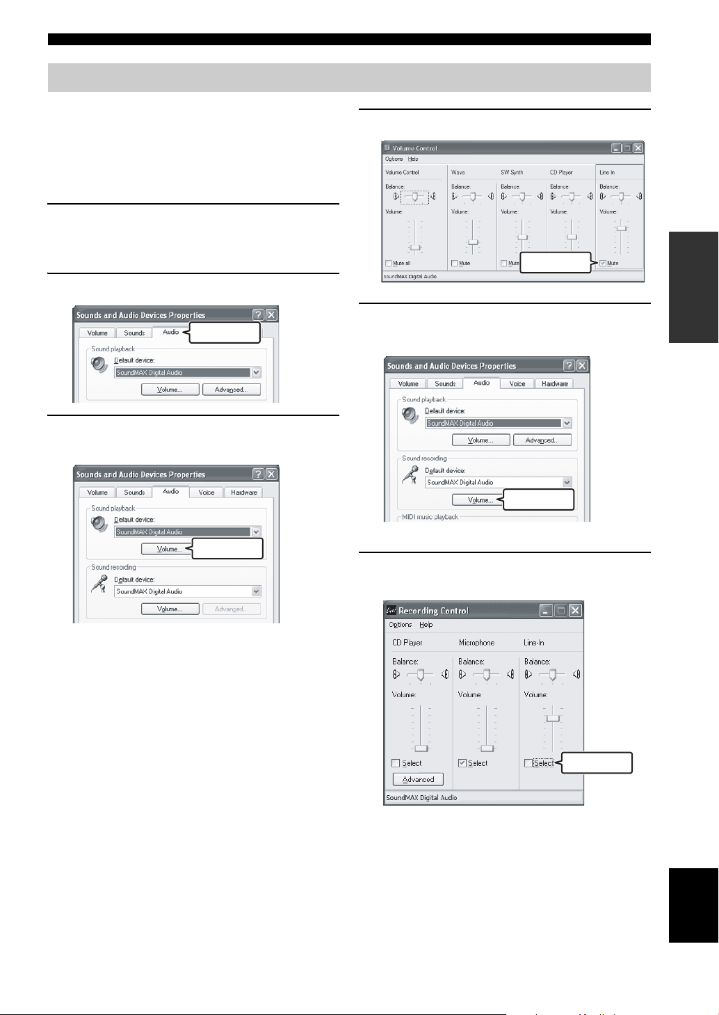
4 Click the “Audio” tab.
1 Click the “Start” menu and click “Settings” -
“Control Panel”.
2 Click “Sounds, Speech and Audio Devices”.
Click.
3 Click “Sounds and Audio Devices”.
The “Sounds and Audio Devices Properties” box
opens.
Click.
PREPARATION
5 Change the settings as follows.
• “Sound Playback” field - “Default device”:
YAMAHA PJP-100UH
• “Sound Recording” field: “Default device”:
YAMAHA PJP-100UH
Change.
Change.
Click.
English
9
Page 14

PREPARATION PROCEDURE
6 Click the “Voice” tab.
7 Change the settings as follows.
• “Voice playback” field - “Default device”:
YAMAHA PJP-100UH
• “Voice recording” field - “Default device”:
YAMAHA PJP-100UH
Change.
Click.
Change.
8 Click “OK” to exit the “Sounds and Audio
Devices Properties” box.
10
Page 15

PREPARATION PROCEDURE
Step 3: Installing this unit in the conference room
Follow the procedure below to install this unit in the place of conference, such as a conference room.
■ Take the positions of the talkers in consideration
To assure the clear conversation by making the most of the effect of arrayed microphones and speakers, place this unit so
that the talkers sit at the area highlighted on the following figure.
Front of this unit
PREPARATION
Side of
this unit
Front of this unit
Side of
this unit
Note
The microphones cannot pick up the audio clearly when the talker sits in one of the positions marked “x” in the figure above.
y
Depending on the using environment, you can configure the setting of the audio pickup area. Refer to “Selecting the audio pickup area
(microphone mode)” (page 16) for details.
■ About installation environment
The speakers of this unit are attached in the downward orientation on the bottom panel. Place this unit horizontally on a
desktop without placing any object below this unit. In case you cannot place the unit stably because of the shape of the
desk or other reasons, attach the supplied pads (3 pieces) as illustrated.
Back panel of this unit
2 pads
1 pad
Attach 1 pad at the center so
that the concave part is
covered.
Concave part
Pad
Display side
Attach 2 pads at the corner so that
the rubber cushions are covered.
Rubber cushion
Pad
English
11
Page 16

CONNECTION USING AUDIO CONNECTION CABLES
CONNECTION USING AUDIO CONNECTION CABLES
In addition to the PC connection through a USB cable, this unit can be connected to a PC or TV conference system
through audio connection cables. Use the following procedure for the connections and settings.
Connecting audio connection cables
Prepare two commercially available audio connection cables (stereo mini-jack cables).
Note
The following description assumes that the input/output terminals of the PC are colored for distinction. If your PC does not have the
colored terminals, consult the instruction manual for you PC to confirm the functions and locations of the input/output terminals before
connection.
(Blue terminal on PC)
To audio input terminal
2
1
To audio output terminal
(Green terminal on PC)
1 Connect the AUDIO IN jack of this unit to the
audio output terminal of the PC or Video
Conference system.
For connection of a PC, connect the cable to the green
terminal of the PC.
2 Connect the AUDIO OUT jack of this unit to
the audio input terminal of the PC or Video
Conference system.
For connection of a PC, connect the cable to the blue
terminal of the PC.
Note
Do not connect the cable to the microphone input
terminal (which is red with the PC) of the PC or
Video Conference system. Otherwise, an excessive
input signal level may degrade the audio quality.
12
Page 17
Changing the settings of PC
The PC settings should be changed so that the audio input
from this unit to the PC is not output to this unit. In
addition, since the audio of this unit is input from the line
input terminal of the PC, it is also necessary to change the
setting so that the audio input from the line input terminal
is accepted.
1 Open the “Sounds and Audio Devices
Properties” box by performing steps 1 to 3
on page 9.
2 Click the “Audio” tab.
Click.
3 In the “Sound Playback” field, click
“Volume...”.
CONNECTION USING AUDIO CONNECTION CABLES
4 In the “Line In” field, click “Mute” to check it.
PREPARATION
Check.
5 In the “Sound recording” field, click
“Volume...”.
Click.
The “Volume Control” box opens.
Click.
The “Recording Control” box opens.
6 In the “Line-In” field, click “Select” to check
it.
Check.
English
13
Page 18

CONNECTION USING AUDIO CONNECTION CABLES
Connection of two units
After connecting the PJP-100UH to a PC, a second PJP-100UH (slave) unit can be connected to the first PJP-100UH
(master) unit through commercially available audio connection cables (stereo mini-jack cables) to make the system
applicable to conferences in a larger space or with a larger number of participants.
Slave PJP Master PJP
To USB port
1 Connect the master PJP-100UH unit and PC
using a USB cable.
See page 8 for details.
2 Connect the AUDIO OUT jack of the PJP-
100UH connected to the PC (master unit) to
the AUDIO IN jack of the second PJP-100UH
(slave unit) using a commercially available
stereo mini-jack cable.
3 Connect the AUDIO IN jack of the PJP-100UH
connected to the PC (master unit) to the
AUDIO OUT jack of the second PJP-100UH
(slave unit) using a commercially available
stereo mini-jack cable.
4 Change the “External input/output” settings
of both the master and slave units.
For details on the setting change, see “Configuring
Settings” (page 15) and “Configuring the external
input/output setting” (page 18).
• Master PJP-100UH: Set to “Connection(mstr)”.
• Slave PJP-100UH: Set to “Connection(slv)”.
14
Page 19

CONFIGURING SETTINGS
You can configure the settings of this unit using the operation keys on this unit.
Note
See “Setting Menu List” (page 16) for details on the setting menu configuration and parameters of each menu item.
1 Press in the initial display.
Settings
1. Sound Settings
2. General Settings
3. Restore Settings
The “Settings” menu appears.
2 Press or to select the menu category,
and then press .
The menu items in the selected category appear. The
following figure shows an example in which “1.
Sound Settings” is selected. For details on the setting
menu configuration, see “Setting Menu List”
(page 16).
Sound Settings
1. Microphone Mode
2. Speaker Mode
3. Room Size
3 Change the parameter.
The following figure shows an example in which “2.
Speaker Mode” is selected. For details on parameters
of each menu item, see “Setting Menu List”
(page 16).
Speaker Mode
1. Monaural
2. Small Area
3. Medium Area
4 To confirm the setting, press .
The setting is saved in this unit.
To return to the previous menu without
saving the setting
Press .
CONFIGURATIONS
15
English
Page 20

SETTING MENU LIST
SETTING MENU LIST
This section describes the setting menu items available with this unit.
Microphone indicators (blue LED) of which direction
Configuring sound settings
■ Selecting the audio pickup area
(microphone mode)
You can select the audio pickup area of the microphone
during call. The default setting is “Zone”.
• Zone: Pick up the audio in large area not only tracking
the audio of the talker. It is suitable for the relatively
quiet environment. Use the area select keys in
“Microphone Mode” menu to specify audio pickup
area, and then press . According to the pressed
keys, the audio in the area of the following figure is
picked up or not.
audio can be picked up from all light up. This mode
indicated by on the display.
y
You can select multiple areas at the same time. The selectable
area’s sets are [ + ], [ + ], [ + ], or all
areas.
• Track: The microphone system automatically tracks
and focuses the audio of the talker not fixing the audio
pickup area (only the one talker’s audio can be picked
up at the same time). The audio can be picked up with
narrow directivity so that the noises other than the taker
can be lessened. It is suitable to pick up the audio
clearly in the environment where there are noises.
Today...
Within 2 m
Microphone indicators (blue LED) of which direction
audio can be picked up from all light up. This mode
indicated by on the display.
y
• Press to pick up audio from all directions.
• You can select multiple areas at the same time. The selectable
area’s sets are [ + ], [ + ], or all areas.
• Spot: Fix the audio pickup area to the two positions
facing the unit with the narrow directivity of the
speaker. It is suitable for the cases that the taker is fixed
one or two persons, or there is equipment produces
noise such as the projector. Use the area select keys in
“Microphone Mode” menu to specify audio pickup
area, and then press . According to the pressed
keys, audio in the areas of the following figure is
picked up or not.
Within 2 m
Within 2 m
Within 2 m
Tracking the talker’s direction automatically
Within 2 m
Next...
Within 2 m
16
Page 21

SETTING MENU LIST
To specify the area to which this feature is available, use
the area select keys in “Microphone Mode” menu, and
then press . According to the pressed keys, audio in
the area of the following figure is picked up or not.
Within 2 m
Within 2 m
Microphone indicators (blue LED) of which direction
audio can be picked up from light up. This mode indicated
by on the display.
y
• Press to pick up audio from all directions.
• You can select multiple areas at the same time.
• You can select areas to where the audio pickup feature is not
applied.
Using the keys on this unit
In the initial display, select “Settings” → “Sound Settings”
→ “Microphone Mode”.
y
You can display “Microphone Mode” menu by pressing
continuously in the initial display or calling display.
■ Configuring the speaker mode
You can select the mode of audio output from the speakers
during call. The default setting is “Divide”.
• Monaural (default): Even during call with more than
one location, the audio from other units is not divided
according to their locations. This mode is indicated by
on the display.
• Small Area: The area from which the audio from other
units is limited as shown below (monaural output).
This mode is indicated by on the display.
• Medium Area: The area from which the audio from
other units is limited as shown below (monaural
output). This mode is indicated by on the display.
• Large Area: The area from which the audio from other
units is limited as shown below (monaural output).
This mode is indicated by on the display.
Using the keys on this unit
In the initial display, select “Settings” → “Sound Settings”
→ “Speaker Mode”.
y
You can display “Speaker Mode” menu by pressing
continuously in the initial display or calling display.
■ Configuring the room size
You can configure this setting depending on the room size
and operating environment. However, you do not need to
change it from “Large” (default setting) normally.
• Large (default): Position for using the unit in an
ordinary conference room, open space or office. The
communication quality is most stable in this position.
This setting is indicated by on the display.
• Medium: Select this position when echo is heard on
the other party of communication with the default
“Large” position. This position is selected when the
unit is used in a room with large reverberations. This
setting is indicated by on the display.
• Small: Select this position when echo is still heard on
the other party of communication with the “Medium”
position. This setting is indicated by on the display.
CONFIGURATIONS
English
17
Page 22

SETTING MENU LIST
Notes
• Room Size is the function for reducing echo on the other party
of communication. Room Size cannot reduce the echo that is
heard from the unit installed on the local location.
• Positions “Medium” and “Small” can improve the echo
processing capability but lowers the communication quality.
These positions should be selected only when echo is heard on
the other party.
Using the keys on this unit
In the initial display or the display during communication,
select “Settings” → “Sound Settings” → “Room Size”.
■ Configuring the external input/output
setting
You need to configure this setting when you connect an
external audio equipment to this unit. The default setting
is “None”.
• None: Disables the external input/output.
• Audio (default): Select this setting when connecting
external audio equipment to this unit.
• Coupled: When coupled connection of two units
(page 14) is used, select this setting on the PJP
connected to the PC through USB (master unit).
Using the keys on this unit
In the initial display, select “Settings” → “Sound Settings”
→ “External I/O”.
Configuring general setting
■ Adjusting the LCD contrast
You can adjust the contrast of the display by press
Using the keys on this unit
In the initial display, select “Settings” → “General
Settings” → “LCD Contrast”.
VOL +/–
Restoring the factory settings
■ Restoring the factory settings of this
unit
You can restore the factory settings of this unit. See
“Resetting the Unit” (page 23) for details.
Note
Restoring the factory settings clears all of the settings you made.
Using the keys on this unit
In the initial display, select “Settings” → “Restore
Settings”.
.
18
Page 23

UPDATING THE FIRMWARE
You can download the firmware (program to control the functions of this unit) to use the latest features.
Software Licensing Agreement
To use the revision upgrading function, you should accept the following software licensing agreement.
1 Permission of use
The present Software Licensing Agreement is intended to
allow Yamaha Corporation (hereinafter referred to as
“Yamaha”) to permit you to use the firmware (hereinafter
“this program”) for Yamaha Conference Microphone
Speaker (hereinafter “this product”). You can download
this program after having accepted the terms and
conditions of the present Software Licensing Agreement.
The present Software Licensing Agreement is applicable
to the downloaded copy of this program as well as to its
duplicates produced in accordance with the present
Software Licensing Agreement.
2 Inhibition of redistribution
You are permitted to download this program only when
you are intended to upgrade the functions of this product.
It is inhibited to upload or post this program in a website
accessible by an unspecified number of the general public
unless there is a permission from Yamaha.
3 Production of duplicates
You may not produce duplicates of this program unless
when it is necessary for backing up purpose or for
upgrading of more than one of this product.
4 Inhibition of decompiling, reverse
engineering or disassembling
You may not decompile, reverse-engineer, disassemble,
alter, permit the use of, distribute or create any derivative
works of this program.
5 Limitation of liabilities
Under any situation including a negligence of its own,
Yamaha will not assume any liabilities on the damage to
the customers caused by the present Software Licensing
Agreement.
6 Export control
You shall comply with all applicable export laws and
regulations of any relevant countries including but not
limited to Japan and your country. You shall not, directly
or indirectly, export or re-export this program except in
compliance with such laws and regulations.
7 Compliance to laws and regulations
This Software Licensing Agreement should be compliant
to the laws and regulations of Japan and your country, and
should be interpreted in accordance with the laws of
Japan.
CONFIGURATIONS
19
English
Page 24

UPDATING THE FIRMWARE
Updating the firmware manually
■ Executing updating
Follow the procedure below.
After the latest firmware is downloaded into a PC, use the
PJP Writer software to transfer the firmware to this unit
and upgrade it.
Notes
• Once revision upgrading of this unit is started, never perform
any other operation until the upgrading is completed and this
unit is restarted. If upgrading is aborted in the middle, this unit
may become unusable and may need servicing by the
manufacturer.
• When revision upgrading is completed, this unit is restarted
automatically so any communication being held will be shut
down.
• Never turn this unit off or disconnect the USB cable in the
middle of revision upgrading. Otherwise, this unit may become
unusable and may need servicing by the manufacturer. If this
unit became unusable, retry revision upgrading before calling
for service.
■ Downloading the PJP Writer software
The PJP Writer software can be downloaded from the PJP
support website.
After accessing the PJP support homepage, go to the
download page and read the explanation on the PJP Writer
software.
Project Phone website:
http://www.yamaha.co.jp/english/product/projectphone/
Note
Before proceeding to upgrading, be sure to exit any PC
software using this unit.
1 Show the initial display of this unit.
2 Launch the PJP Writer on the PC connected
to this unit through USB.
3 Click or to select the file to be used in
revision upgrading.
• : Click to download the latest firmware from
the website.
• : Click and specify the firmware save location
in the PC.
4 Click to start the file transfer.
When file transfer is completed, the revision
upgrading processing starts automatically.
The firmware update process takes a few
minutes to complete.
MIC MUTE (red LED) on the top panel of this unit
flashes during the firmware update process. Do not turn
this unit off while MIC MUTE (red LED) flashes.
■ When the firmware update is complete
This unit restarts automatically.
20
Page 25

TROUBLESHOOTING
Refer to the following tables when this unit does not function properly. If the problem you are experiencing is not listed
or if the instruction does not help, contact the nearest authorized YAMAHA dealer or service center.
First, check if the microphone indicators light up. If the indicator is turned off, see “Q1: LED indicators do not light up”
below. Otherwise, consult “Q2: A problem in the communication audio” (page 22).
Q1: LED indicators do not light up
Problem Cause Remedy
The microphone indicators do not
light up.
This unit is not turned on. Check that the AC adapter and power cable
The power cable is not connected to the AC
outlet.
The main or branch circuit breaker is shut
off.
There is a power failure. Wait until the power supply is restored.
Power is not supplied to the AC outlet.
(Carry out the test by connecting another
electrical appliance to the AC outlet.)
The microphones are muted (the MIC MUTE
LED lights up).
are connected properly.
If this unit has been turned off by pressing
and holding MIC MUTE (page 4), pressing
any key of this unit turns it on again.
Check that the power cable is connected to
the AC outlet properly.
If the circuit breaker is tripped to “OFF”, set
it to “ON”.
If the circuit breaker is “ON”, set it to “OFF”
then “ON” again.
If another appliance can neither be turned on,
have the power outlet or power wiring
serviced.
If another appliance can be turned on, have
this unit serviced.
Press MIC MUTE so that the MIC MUTE
LED is turned off.
INFORMATION
ADDITIONAL
21
English
Page 26

TROUBLESHOOTING
Q2: A problem in the communication audio
Problem Cause Remedy
The audio from the other unit cannot
be heard.
The audio is interrupted. Audio connection cables are disconnected or
The unit generates feedback noises. The unit is located against a wall. Locate the unit at a certain distance from a
The microphones are muted on the other
unit.
connected improperly.
USB cable is disconnected or connected
improperly.
The USB cable is not connected properly. Check that the USB cable is connected
An object is placed near this unit. Avoid placing an object in front of the
This unit is used in a room with high
reverberation.
Connect the audio connection cables
securely.
Connect the USB cable securely.
firmly.
wall.
microphones.
Place objects with high sound absorbance in
the room by avoiding the positions in front of
the microphones.
Avoid talking at a loud voice to reduce
reverberations.
22
Page 27

RESETTING THE UNIT
You can restore the factory settings of this unit.
Notes
Before restoring the factory settings, note the following.
• All of the settings that have the default settings are set to the
default settings.
• Once the factory settings are restored, the previous settings
made by the user cannot be recalled.
• Once revision upgrading is executed, the firmware version of
this unit will not return to the factory-shipped version even
when this unit is reset.
Follow the procedure below to restore the factory settings
using the keys on this unit.
MIC/SPALL
MIC/SP AREA SELECT
MIC MUTE VOL
DC IN 12V IN AUDIO OUT
1 Press in the initial display.
The “Settings” menu appears.
2 Press , and then press or to select
“3. Restore Factory Settings”.
Settings
1. Sound Settings
2. General Settings
3. Restore Settings
3 Press .
The “Restore Settings” menu appears.
Restore Settings
1. Yes
2. No
4 Select “1. Yes”, and then press .
The settings of this unit are reset to the factory
settings, and the “Settings” menu reappears.
INFORMATION
ADDITIONAL
Settings
1. Sound Settings
2. General Settings
3. Restore Settings
To cancel resetting in the middle
In step 4, press , or press or to select “2. No”
and then press .
English
23
Page 28

SPECIFICATIONS
SPECIFICATIONS
General
• Dimensions (W x H x D) ...................... 750 mm x 100 mm x 65mm
• Weight (excl. AC adapter)....................................................... 2.9 kg
• Power supply ........................................ 100 to 240 V AC (50/60 Hz)
• Power consumption .................................................... Approx. 36 W
(29.5 in. x 3.9 in. x 2.6 in.)
(6.4 lbs)
Operating environment
• Ambient temperature ......................................................... 0 to 40°C
• Ambient humidity ............................ 20% to 85% (no condensation)
(32 to 104 °F)
Radio interference standard
............................................................................ FCC Part 15 (US)
EN55022 (EU)
USB interfaces
USB 2.0 Full Speed
• Compliant to USB audio class and HID class
USB audio format
• Record/reproduce channels
• PCM sampling frequency........................................................16 kHz
• Quantization .............................................................................. 16-bit
When dedicated application is used
• PCM sampling frequency........................................................16 kHz
• Quantization .............................................................................. 16-bit
• 3-channel outputs (audio separation by location)
Audio input/output interfaces
................................................ Stereo analog input/output (1 each)
• Connectors........................................................................ Mini-jacks
Audio
• Arrayed microphones (directivity controlled)
• Zone audio pickup function
• Spot audio pickup function
• Microphone auto tracking function
Signal processing
• 3CH adaptive echo canceller
• Microphone/speaker array control
Accessories
• AC adapter (PJP-PS01) x 1
• Power cable x 1
• USB cable x 1
• Owner’s manual (this manual) x 1
• Warranty card x 1
*Specifications are subject to change without notice.
Serial interface
.......................................................................................... RS-232C
• Connectors.......................................................................... Mini DIN
NOTES FOR TRANSFER/DISPOSAL OF THIS UNIT
Restore the factory settings before transferring or disposing of this unit.
Note
When transferring this unit, be sure to transfer with the owner’s manual (this manual).
If this unit is transferred or disposed of without restoring the factory settings, information may be misused by a third
party.
For instructions on how to restore the factory settings, see “Resetting the Unit” (page 23).
24
Page 29

©
This owner’s manual is based on the firmware version 1.0x. The
functions and specifications could be possibly added or changed by a
firmware update.
Visit the PJP website to obtain the latest firmware and manuals.
PJP website:
http://www.yamaha.co.jp/english/product/projectphone/
Ce mode d’emploi se réfère à la version 1.0x du micrologiciel. Des
fonctions et spécifications peuvent être ajoutées ou changées par une
mise à jour du micrologiciel.
Consultez le site PJP pour obtenir les tout derniers micrologiciel et
manuels.
Site PJP:
http://www.yamaha.co.jp/english/product/projectphone/
Dieses Benutzerhandbuch basiert auf der Firmware-Version 1.0x. Die
Funktionen und technischen Daten können möglicherweise durch eine
zukünftige Firmware-Aktualisierung erweitert oder geändert werden.
Besuchen Sie die PJP-Website zum Erhalten der neuesten Firmware
und Anleitungen.
PJP-Website:
http://www.yamaha.co.jp/english/product/projectphone/
YAMAHA ELECTRONICS CORPORATION, USA
2006 All rights reserved.
6660 ORANGETHORPE AVE., BUENA PARK, CALIF. 90620, U.S.A.
Printed in XXX
XX00000
 Loading...