

Page 1

Paging Station Microphone
PGM1
Paging Station Extension
PGX1
EnglishDeutschFrançaisEspañolPortuguêsItalianoРусский
Installation Manual
Installationshandbuch
Manuel d’installation
Manual de instalación
Manual de instalação
Manuale all’installazione
Руководство по установке
施工説明書
EN
DE
FR
ES
PT
IT
RU
JA
日本語
Page 2

1. IMPORTANT NOTICE: DO NOT MODIFY
THIS UNIT!
This product, when installed as indicated in
the instructions contained in this manual,
meets FCC requirements. Modifications not
expressly approved by Yamaha may void your
authority, granted by the FCC, to use the product.
2. IMPORTANT: When connecting this product
to accessories and/or another product use
only high quality shielded cables. Cable/s sup-
plied with this product MUST be used. Follow
all installation instructions. Failure to follow
instructions could void your FCC authorization
to use this product in the USA.
3. NOTE: This product has been tested and
found to comply with the requirements listed in
FCC Regulations, Part 15 for Class “B” digital
devices. Compliance with these requirements
provides a reasonable level of assurance that
your use of this product in a residential environment will not result in harmful interference
with other electronic devices. This equipment
generates/uses radio frequencies and, if not
installed and used according to the instruc-
tions found in the users manual, may cause
interference harmful to the operation of other
electronic devices. Compliance with FCC reg-
ulations does not guarantee that interference
will not occur in all installations. If this product
is found to be the source of interference, which
can be determined by tur
n
ing the unit “OFF”
and “ON”, please try to eliminate the problem
by using one of the following measures:
Relocate either this product or the device that
is being affected by the interference.
Utilize power outlets that are on different
branch (circuit breaker or fuse) circuits or
install AC line filter/s.
In the case of radio or TV interference, relocate/reorient the antenna. If the antenna leadin is 300 ohm ribbon lead, change the lead-in
to co-axial type cable.
If these corrective measures do not produce
satisfactory results, please contact the local
retailer authorized to distribute this type of
product. If you can not locate the appropriate
retailer, please contact Yamaha Corporation of
America, Electronic Service Division, 6600
Orangethorpe Ave, Buena Park, CA90620
The above statements apply ONLY to those
products distributed by Yamaha Corporation of
America or its subsidiaries.
(class B)
FCC INFORMATION (U.S.A.)
This device complies with Part 15 of the FCC Rules. Operation is subject to the following two conditions:
(1) this device may not cause harmful interference, and (2) this device must accept any interference
received, including interference that may cause undesired operation.
CAN ICES-3 (B)/NMB-3(B)
(can_b_02)
이 기기는 가정용(B 급) 전자파적합기기로서 주로 가정에서 사용하는 것을 목적으로 하며, 모든 지역에
서 사용할 수 있습니다.
2 PGM1/PGX1 Installation Manual
(class b korea)
Page 3
PA_en_8 1/2
PRECAUTIONS
PLEASE READ CAREFULLY
BEFORE PROCEEDING
Please keep this manual in a safe
place for future reference.
WARNING
Always follow the basic precautions
listed below to avoid the possibility of
serious injury or even death from
electrical shock, short-circuiting,
damages, fire or other hazards. These
precautions include, but are not limited
to, the following:
Do not open
• This device contains no user-serviceable
parts. Do not open the device or attempt to
disassemble the internal parts or modify
them in any way. If it should appear to be
malfunctioning, discontinue use
immediately and have it inspected by
qualified Yamaha service personnel.
Water warning
• Do not expose the device to rain, use it
near water or in damp or wet conditions, or
place on it any containers (such as vases,
bottles or glasses) containing liquids which
might spill into any openings. If any liquid
such as water seeps into the device, turn
off the power of the PoE injector or the PoE
network switch immediately and unplug
the cable. Then have the device inspected
by qualified Yamaha service personnel.
• Never insert or remove an electric plug
with wet hands.
Fire warning
• Do not place any burning items or open
flames near the device, since they may
cause a fire.
If you notice any abnormality
• If any of the following problems occur,
immediately turn off the PoE injector or the
PoE network switch and disconnect the
cable.
- Unusual smells or smoke are emitted.
- Some object has been dropped into the
device.
- There is a sudden loss of sound during
use of the device.
- Cracks or other visible damage appear
on the device.
Then have the device inspected or
repaired by qualified Yamaha service
personnel.
CAUTION
Always follow the basic precautions
listed below to avoid the possibility of
physical injury to you or others, or
damage to the device or other property.
These precautions include, but are not
limited to, the following:
Location
• Do not place the device in an unstable
position where it might accidentally fall
over and cause injuries.
• Do not place the device in a location where
it may come into contact with corrosive
gases or salt air. Doing so may result in
malfunction.
• Before moving the device, remove all
connected cables.
3PGM1/PGX1 Installation Manual
Page 4

Handling caution
• Do not insert your fingers or hands in any
gaps or openings on the device (panel,
etc.).
• Avoid inserting or dropping foreign objects
(paper, plastic, metal, etc.) into any gaps
or openings on the device (panel, etc.) If
this happens, immediately turn off the
power of the PoE injector or the PoE
network switch, unplug the cable, and
have the device inspected by qualified
Yamaha service personnel.
• Do not rest your weight on the device or
place heavy objects on it. Avoid applying
excessive force to the buttons, switches or
connectors to prevent injuries.
• Avoid pulling the connected cables to
prevent injuries or damage to the device
by causing it to fall.
Yamaha cannot be held responsible for
damage caused by improper use or
modifications to the device.
PA_en_8 2/2
4 PGM1/PGX1 Installation Manual
Page 5

NOTICE
To avoid the possibility of malfunction/ dam-
age to the product, damage to data, or dam-
age to other property, follow the notices
below.
Handling and maintenance
• Do not use the device in the vicinity of a TV,
radio, AV equipment, mobile phone, or other
electric devices. Otherwise, the device, TV,
or radio may generate noise.
• Do not expose the device to excessive dust
or vibration, or extreme cold or heat (such
as in direct sunlight, near a heater, or in a
car during the day), in order to prevent the
possibility of panel disfiguration, unstable
operation, or damage to the internal components.
• Do not place vinyl, plastic or rubber objects
on the device, since this might discolor the
panel.
• When cleaning the device, use a dry and
soft cloth. Do not use paint thinners, solvents, cleaning fluids, or chemical-impreg-
nated wiping cloths.
• Condensation can occur in the device due to
rapid, drastic changes in ambient temperature—when the device is moved from one
location to another, or air conditioning is
tu
rned on or off, for example. Using the
devic
e
while condensation is present can
cause damage. If there is reason to believe
that condensation might have occurred,
leave the device for several hours without
turning on the power until the condensation
has completely dried out.
Information
Regarding disposal
• This product contains recyclable components. When disposing of this product,
please contact the appropriate local authorities.
About this manual
• The illustrations as shown in this manual are
for instructional purposes only.
• The company names and product names in
this manual are the trademarks or registered
trademarks of their respective companies.
•Software may be revised and updated with-
out prior notice.
The model number, serial number, power
requirements, etc., may be found on or
near the name plate, which is at the bot-
tom of the unit.
Yo u should note this serial number in the
space provided below and retain this
manual as a permanent record of your
purchase to aid identification in the event
of theft.
Model No.
Serial No.
(bottom_en_01)
5PGM1/PGX1 Installation Manual
Page 6

Contents
PRECAUTIONS .....................................................................3
Introduction .......................................................................7
Features ...........................................................................7
What you’ll need to provide ....................................................7
Controls and Connectors (PGM1) ..............................................8
Top Panel ...................................................................................................8
Rear Panel..................................................................................................9
Bottom Panel............................................................................................11
Controls and Connectors (PGX1) ............................................. 12
Top Panel .................................................................................................12
Bottom Panel............................................................................................12
Initializing the PGM1 .......................................................... 13
Connecting the PGM1 to an MTX/MRX system ............................ 14
About the priority mic ..............................................................................14
Connecting a PGX1............................................................. 16
Indicator list .................................................................... 17
Status indicator........................................................................................17
Indicator operation diagram.....................................................................17
Alert list.......................................................................... 18
Specifications ................................................................ 133
Dimensions .................................................................... 135
Included items
• PGM1/PGX1 Installation Manual (this document)
• PGM1/PGX1 Zone label (1 sheet)
• PGM1: Gooseneck mic
• PGX1: Connecting bracket, dedicated screws (8 pcs.), connection cable
Firmware update
MTX-MRX Editor is used to update the firmware of the PGM1/PGX1 and to check the
version. For details on how to perform these operations, refer to “MTX-MRX Editor User
Guide.”
The latest firmware can be downloaded from the download page of the following website.
http://www.yamahaproaudio.com/
6 PGM1/PGX1 Installation Manual
Page 7

Introduction
Thank you for purchasing the Yamaha PGM1 paging station microphone or the PGX1
paging station extension. These products are a paging station microphone and an exten-
sion unit used in an installed system for on-premises broadcast. This installation manual
explains installation methods for the installing technician or the designer. Be sure to
read this installation manual before installing the units. After reading this manual, keep
it for future reference.
Features
The PGM1/PGX1 are paging stations that can be used with the MTX5-D or MRX7-D. They pro-
vide the following features.
• Paging stations can be networked via a Dante network and PoE (Power over Ethernet).
• Chimes and messages can be played back using an SD card player.
•Two PGX1 units can be added for each PGM1 unit, allowing you to specify broadcast
regions in detail and to select from numerous messages.
•You can use MTX-MRX Editor to install up to four PGM1 units in one MTX/MRX system. One
of these PGM1 units can be specified as the priority mic.
What you’ll need to provide
• PoE injector or PoE network switch that supports IEEE802.3af
This is used between the MTX/MRX system and the PGM1 in order to supply power to the
PGM1 and the PGX1.
PoE injector units and PoE network switches are collectively referred to as “PSE (Power
Sourcing Equipment).”
• Ethernet cables (CAT5e or better)
These are used between the MTX/MRX system and the PSE, and between the PSE and the
PGM1.
• Phillips screwdriver
This is used when connecting a PGX1.
7PGM1/PGX1 Installation Manual
Page 8
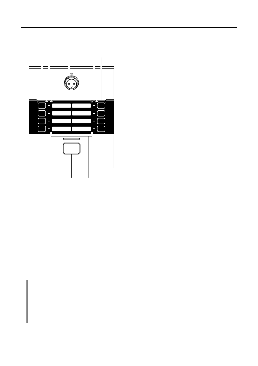
Controls and Connectors (PGM1)
eq eww
ytr
Top Panel
w Zone/message select buttons
These buttons select the zone(s) to which
the mic will broadcast, or select messages saved on the SD card. Use MTXMRX Editor to assign zones or messages
to these buttons. More than one broad-
cast zone can be selected at the same
time. Only one message can be selected.
For details on how to make settings, refer
to “MTX-MRX Editor User Guide.”
e Zone/message indicators
These indicators light to indicate the cur-
rently selected zone(s) or message.
r Status indicator
This indicator is lit green when broadcast
from the mic is possible. Duri
cast, the indicator is lit red. For other indications, refer to page 17.
t PTT (Push To Talk) button
Press this button to switch the mic on/off.
q Mic input jack
Connect the included gooseneck mic
(condenser mic) here.
To connect the mic, plug it straight into
the mic input jack.
To rem o ve the mic, pull the mic upward
while pressing an ejector tool (a thin
metal rod of about 2, or a very thin
screwdriver) into the hole located above
the mic input jack. When doing so, firmly
grasp the base of the mic’s connector.
NOTICE
• Because the phantom power supply is
always on, you should connect the mic
when power is not being supplied to the
unit.
• Do not connect any mic or device other
than the included mic.
Yo u can use MTX-MRX Editor to change
the operation of this button between
latched and unlatched.
y Labels
Labels with the name of each zone can
be inserted here. You can create labels
using PGM1 Label Creator which is
included with MTX-MRX Editor.
ng bro
ad-
8 PGM1/PGX1 Installation Manual
Page 9

Rear Panel
terwq
[UNIT ID]
rotary switch
DIP switches
123
123
q [UNIT ID] rotary switch
This specifies the ID by which individual
PGM1 units are distinguished within the
MTX/MRX system’s network. In conjunc-
tion with device setting DIP switches 1–3
w which specify the upper place, this
rotary switch specifies the lower place,
allowing you to set the UNIT ID in the
range of 01 to 7F.
NOTE
•A rubber cap is attached here when the unit
is shipped from the factory; remove the rub-
ber cap to change the switch setting. To pre-
vent dust from entering, reattach the rubber
cap after you have made the setting.
• Do not set the UNIT ID to 00.
• After setting the [UNIT ID] rotary switch,
power-off the PoE injector / PoE network
switch (PSE) and then power it on again.
w Device setting DIP switches
These switches make settings related to
how the unit starts up. A label explaining
the settings is affixed to the bottom panel.
Making the settings
Before changing the settings, turn off
the power of the PSE. Even if you
change the settings while the power
is on, the changed settings are not
applied until the power is turned off
once.
Controls and Connectors (PGM1)
For details, see below.
Switch
Status
Switch
Status
The switch is in the upward
(OFF) position.
The switch is in the downward
(ON) position.
• Switches 1–3 (UNIT ID)
These switches specify the upper place
of the UNIT ID; used in conjunction with
the [UNIT ID] rotary switch described
above which specifies the lower place,
you can set the UNIT ID in a range of
it
127 possibil
Example setting)
Setting the UNIT ID to [0A]
ies.
0A
ON
12345678
Switch
Setting UNIT ID is “0x”
The [UNIT ID] rotary switch
Function
Switch
Setting UNIT ID is “1x”
Function
setting has a range of 01
through 0F.
The [UNIT ID] rotary switch
setting has a range of 10
through 1F.
9PGM1/PGX1 Installation Manual
Page 10

Controls and Connectors (PGM1)
123
123
123
123
123
123
6
6
Switch
Setting UNIT ID is “2x”
The [UNIT ID] rotary switch
Function
Switch
Setting UNIT ID is “3x”
Function
Switch
Setting UNIT ID is “4x”
Function
Switch
Setting UNIT ID is “5x”
Function
Switch
setting has a range of 20
through 2F.
The [UNIT ID] rotary switch
setting has a range of 30
through 3F.
The [UNIT ID] rotary switch
setting has a range of 40
through 4F.
The [UNIT ID] rotary switch
setting has a range of 50
through 5F.
• Switches 4–5
Not used. Leave these in the factory-set
position (upward).
• Switch 6 (IP SETTING)
Specifies how to set the IP address
used for communicating with external
devices.
Switch
Setting UNIT ID
The IP address is determined
Content
Switch
Setting PC
Content
by the UNIT ID, and will be
“192.168.0.(UNIT ID)”.
The IP address is determined
by the setting in MTX-MRX
Editor (see “MTX-MRX Editor
User Guide”).
NOTE
Yo u must set the “UNIT ID” the first time you
connect this unit to a computer after pur-
chase. Also, if you subsequently want to
specify an IP address without using the UNIT
ID, use MTX-MRX Editor to specify the IP
address and then switch to “PC.”
Setting UNIT ID is “6x”
The [UNIT ID] rotary switch
Function
Switch
Setting UNIT ID is “7x”
Function
setting has a range of 60
through 6F.
The [UNIT ID] rotary switch
setting has a range of 70
through 7F.
10 PGM1/PGX1 Installation Manual
Page 11

Controls and Connectors (PGM1)
78
78
• Switches 7–8 (START UP MODE)
Specify how the unit is initialized after
the power turns on.
Switch
Setting RESUME
This is the normal operating
mode.
Content
Switch
Setting INT. (INITIALIZE)
Content
When the PGM1’s power is
turned on, it starts up while
preserving the state in which it
was immediately prior to pow-
ering-off.
The unit is initialized to the factory settings (page 13).
e Dante/NETWORK connector
This is an RJ45 port for connecting a
Dante device such as the MRX7-D using
an Ethernet cable (CAT5e or better) via
PSE.
NOTE
• Do not connect anything other than a Danteenabled device or a device that supports
gigabit Ethernet (including computers).
• The maximum cable length that can be
used is 100 meters.
• Use STP (Shielded Twisted Pair) cable to
prevent electromagnetic interference.
Bottom Panel
q
q 8-pin dedicated connector
This is a dedicated connector for connection to the PGX1.
When the unit is shipped from the factory,
a rubber cap is attached here.
r SYNC indicator
This indicator shows the operating status
of the Dante network.
When the green indicator is lit, this indicates that the unit is the clock slave and
that the clock is synchronized.
When the green indicator is flashing, this
indicates that the unit is the clock master.
t LINK/ACT indicator
This indicator shows the communication
status of the Dante/NETWORK connector.
If the Ethernet cable is connected correctly, the indicator flashes rapidly.
11PGM1/PGX1 Installation Manual
Page 12

Controls and Connectors (PGX1)
wewqq
Top Panel
q Zone/message select buttons
These buttons select the zone(s) to which
the mic will broadcast, or select messages saved on the SD card. Use MTXMRX Editor to assign zones or messages
to these buttons. More than one broad-
cast zone can be selected at the same
time. Only one message can be selected.
For details on how to make settings, refer
to “MTX-MRX Editor User Guide.”
w Zone/message indicators
These indicators light to indicate the cur-
rently selected zone(s) or message.
Bottom Panel
q q
q 8-pin dedicated connector
This is a dedicated connector for connection to the PGM1 or PGX1.
e Labels
Labels with the name of each zone can
be inserted here. You can create labels
using PGM1 Label Creator which is
included with MTX-MRX Editor.
12 PGM1/PGX1 Installation Manual
Page 13

Initializing the PGM1
If you want to return (initialize) the unit to its factory-set state, for example because the installation location has changed, proceed as follows.
1. Power-off the PSE.
2. On the rear panel, set device settings
DIP switch 7 to the downward position, and set switch 8 to the upward
(INT.) position.
ON
12345678
78
3. Power-on the PSE.
Initialization begins.
• Initialization in progress:
All zone indicators flash rapidly.
• Initialization completed:
All zone indicators flash slowly.
• Initialization failed:
The status indicator flashes slowly.
NOTICE
Do not power-off the PSE while initialization is in progress. Doing so will cause
malfunctions.
4. Verify that initialization is completed,
and then power-off the PSE.
5. Set device settings DIP switches 7
and 8 both to the upward (RESUME)
position.
78
6. Power-on the PSE.
The unit starts up in the factory-set
state.
13PGM1/PGX1 Installation Manual
Page 14

Connecting the PGM1 to an MTX/MRX system
P
P
PGX1
ID=0
PGX1
ID=1
PGM1
ID=60
PGX1
ID=0
PGX1
ID=1
PGM1
ID=61
PGX1
ID=0
PGX1
ID=1
PGM1
ID=62
MRX7-D ID=01
Group 1
= priority mic
SWR2100P-10G
Group 2
MTX5-D ID=02
PGX1
ID=0
PGX1
ID=1
PGM1
ID=63
Up to four PGM1 units can be connected to one MTX/MRX system.
Up to two PGX1 units can be connected to one PGM1 unit.
The PGM1 and PGX1 can control the parameters of any single MRX7-D or MTX5-D unit within
the MTX/MRX system.
For details, refer to “MTX-MRX Editor User Guide.”
About the priority mic
Of the PGM1 units connected to an MRX7-D or MTX5-D, one unit can be specified as the priority mic.
When the priority mic begins broadcasting, the other mics in the group are muted.
Within the group, mics other than the priority mic are given first-come first-served priority.
NOTICE
Do not connect or disconnect cables while the PSE is on.
14 PGM1/PGX1 Installation Manual
P
Page 15

Connecting the PGM1 to an MTX/MRX system
Computer
MRX7-D
PoE injector
PGM1
Maximum 100 meters
MRX7-D
PGM1
XMV8280-D
PGM1 PGM1 PGM1
Maximum
100 meters
SWR2100P-10G
SWP1-16MMF
Computer
1. Use the rotary switch and DIP switches of each unit to specify its UNIT ID.
2. Connect a PoE network switch that can work with Dante within the Dante network,
and use an Ethernet cable to connect the PGM1 to the network switch. If the network
switch does not support PoE, connect a PoE injector between the network switch
and the PGM1.
In some cases, the PSE (PoE network switch or PoE injector) might have ports that supply
power and ports that do not supply power. Connect the PGM1 to a port that supplies
power. For details on how to synchronize each device, refer to “MTX-MRX Editor User
Guide.”
3. With the PGM1 and the PSE connected, power-on the PSE.
Connections for a small system
Connections for a large system
15PGM1/PGX1 Installation Manual
Page 16

Connecting a PGX1
PGX1 PGM1
Connecting bracket
Connecting bracket
PGX1 PGM1
Up to two PGX1 units can be connected to one PGM1 unit.
NOTICE
• Before making connections, detach the Ethernet cable and gooseneck mic.
• Make sure to place a soft cloth underneath the device so that the surface of the body will not be
damaged.
1. Turn the PGM1 and PGX1 units over on their back.
2. Place the PGM1 on the right, and place the PGX1 to be connected on the left.
3. Remove the rubber cap from the bottom panel of the PGM1.
4. Use the included connection cable to connect the PGM1 and PGX1.
5. Place the connecting bracket between the two units, and fasten the screws (at the 8
locations shown below) on the PGX1 side to secure it.
6. Place the rubber cap that you removed from PGM1 into the socket of the unused
dedicated 8-pin connector of the PGX1.
If you want to connect a second PGX1 unit, you can do so in a similar way.
16 PGM1/PGX1 Installation Manual
Page 17

Indicator list
PTT: ON PTT: OFF
Level
0 db
Mic Input
SD Input
Range
-∞
Attack
Opening
Chime
Closing
Chime
Release
Time
Program Output
Chime (SD)
Mic Output/
Message (SD)
Green Flashing red Red Green
Green Orange Green
PTT indicator
(mic being operated)
PTT indicator
(mic not being operated)
(Preparing) (Broadcasting)
*Pressing PTT during broadcast will stop the broadcast.
* It is not necessary to press PTT when finished.
Status indicator
Lit green Broadcast is possible
Lit orange Broadcast is not possible because another mic is broadcasting
Lit red Broadcasting
Flashing red Preparing to broadcast
Flashing orange Interrupted by the priority mic
Indicator operation diagram
17PGM1/PGX1 Installation Manual
Page 18

Alert list
The following table lists the alerts generated by the PGM1/PGX1, their meaning, and the
appropriate action to take.
When the status indicator flashes alternately in green and orange, the contents of the alert
message are indicated at the position of the flashing zone / message indicator. The upper left
zone / message indicator is set to alert number 1, and the lower right zone / message indicator
is set to alert number 8.
If the problem cannot be solved, contact your Yamaha dealer listed at the end of this manual.
Flashing zone/
message indicator
(alert number)
1
2
5
6
The device has not started
up correctly.
The data saved in internal
memory has been lost.
Duplicate IP addresses.
IP address was not set
within 60 seconds of
startup.
The UNIT ID is set to “00.” Set the UNIT ID to something other than “00.”
Devices with identical UNIT
IDs were found connected
within the same network.
Meaning Response
Turn off the power of the PSE, then turn on after
waiting at least 6 seconds. If this does not solve
the problem, please initialize the PGM1. Should
this also fails, contact your Yamaha dealer.
Change the IP addresses or UNIT ID so that there
are no duplicates.
Please check rear panel DIP switch 6 (IP SETTING). If DIP switch 6 is set to “PC,” use the system’s dedicated application software or the DHCP
server to specify the device IP address.
Change the UNIT ID so that there are no dupli-
cates.
18 PGM1/PGX1 Installation Manual
Page 19

Specifications
General specifications
PGM1 PGX1
Dimensions
Weight
Power supply voltage
Power consumption
Operating temperature range
Storage temperature
range
Maximum number of
units usable simultaneously
132(W) × 56(H) × 154(D) mm
(excluding mic)
1.2 kg (including mic)
1. 0 k g ( excluding mic)
Power supplied via PoE
(IEEE802.3af)
4.8W max. (same whether PGM1 is used by itself or with an added PGX1)
0°C–40°C
-20°C–60°C
PGX1
A maximum of two
units can be added for each PGM1 unit
A maximum of four PGM1 units can be installed in one MTX/MRX system (There are limits on the total number of units within a system that
includes other devices)
Operating lifespan 10 years
Included items
Gooseneck mic, Zone label,
Installation Manual
Electrical specifications
Sampling frequency 48kHz/44.1kHz
Digital input/output
format
Format Cable
requirements
* The contents of this manual apply to the latest specifications as of the publishing date. To obtain the latest man-
ual, access the Yamaha website then download the manual file.
* Der Inhalt dieser Bedienungsanleitung gilt für die neuesten technischen Daten zum Zeitpunkt der Veröffentli-
chung. Um die neueste Version der Anleitung zu erhalten, rufen Sie die Website von Yamaha auf und laden Sie
dann die Datei mit der Bedienungsanleitung herunter.
* Le contenu de ce mode d’emploi s’applique aux dernières caractéristiques techniques connues à la date de
publication du manuel. Pour obtenir la version la plus récente du manuel, accédez au site Web de Yamaha puis
téléchargez le fichier du manuel concerné.
* El contenido de este manual se a
el último manual, acceda al sitio web de Yamaha y descargue el archivo del manual.
* O conteúdo deste manual se aplica às especificações mais recentes a partir da data de publicação. Para obter o
manual mais recente, acesse o site da Yamaha e faça o download do arquivo do manual.
* Il contenuto del presente manuale si applica alle ultime specifiche tecniche a partire dalla data di pubblicazione.
Per ottenere la versione più recente del manuale, accedere al sito Web Yamaha e scaricare il file corrispondente.
* В содержании данного руководства приведены последние на момент публикации технические характе-
ристики. Для получения последней версии руководства посетите веб-сайт корпорации Yamaha и загрузите файл с руководством.
* 本書は、発行時点での最新仕様で説明しています。最新版は、ヤマハウェブサイトからダウンロードできます。
Dante
Dante/NETWORK connector: 1000Base-T
Dante/NETWORK connector: CAT5e or better Ethernet STP cable
p
lica a las últimas especificaciones según la fecha de publicación. Para obtener
132(W) × 56(H) × 154(D) mm
0.9 kg
(excluding connecting bracket)
Power supplied from PGM1
Zone label, Installation Manual,
Connecting bracket, dedicated
screws (8 pcs.), connection cable
PGM1
133PGM1/PGX1 Installation Manual
Page 20

European models
Purchaser/User Information specified in EN55103-2:2009.
Conforms to Environments: E1, E2, E3 and E4
134 PGM1/PGX1 Installation Manual
Page 21

Dimensions
111±2 152±2
505±10
56
4
132
154
Ø
12
110
22
14°
84
PGM1
Gooseneck
microphone
Unit: mm
135PGM1/PGX1 Installation Manual
Page 22

Dimensions
56
4
132
154
Ø
12
110
22
14°
84
PGX1
Unit: mm
136 PGM1/PGX1 Installation Manual
Page 23

137PGM1/PGX1 Installation Manual
Page 24

Information for users on collection and disposal of old equipment
This symbol on the products, packaging, and/or accompanying documents means that used electrical
and electronic products should not be mixed with general household waste.
For proper treatment, recovery and recycling of old products, please take them to applicable collection
points, in accordance with your national legislation.
By disposing of these products correctly, you will help to save valuable resources and prevent any
potential negative effects on human health and the environment which could otherwise arise from inap-
propriate waste handling.
For more information about collection and recycling of old products, please contact your local municipality, your waste
disposal service or the point of sale where you purchased the items.
For business users in the European Union:
If you wish to discard electrical and electronic equipment, please contact your de
Information on Disposal in other Countries outside the European Union:
This symbol is only valid in the European Union. If you wish to discard these items, please contact your local authori-
ties or dealer and ask for the correct method of disposal.
aler or sup
plier for further information.
(weee_eu_en_02)
Verbraucherinformation zur Sammlung und Entsorgung alter Elektrogeräte
Befindet sich dieses Symbol auf den Produkten, der Verpackung und/oder beiliegenden Unterlagen,
so sollten benutzte elektrische Geräte nicht mit dem normalen Haushaltsabfall entsorgt werden.
In Übereinstimmung mit Ihren nationalen Bestimmungen bringen Sie alte Geräte bitte zur fachgerechten
Entsorgung, Wiederaufbereitung und Wiederverwendung zu den entsprechenden Sammelstellen.
Durch die fachgerechte Entsorgung der Elektrogeräte helfen Sie, wertvolle Ressourcen zu schützen,
und verhindern mögliche negative Auswirkungen auf die menschliche Gesundheit und die Umwelt, die
andernfalls durch unsachgerechte Müllentsorgung auftreten könnten.
r
weitere Informationen zum Sammeln und Wiederaufbereiten alter Elektrogeräte kontaktieren Sie bitte Ihre örtliche
Fü
Stadt- oder Gemeindeverwaltung, Ihren Abfallentsorgungsdienst oder die Verkaufsstelle der Artikel.
Information für geschäftliche Anwender in der Europäischen Union:
Wenn Sie Elektrogeräte ausrangieren möchten, kontaktieren Sie bitte Ihren Händler oder Zulieferer für weitere Infor-
mationen.
Entsorgungsinformation für Länder außerhalb der Europäischen Union:
Dieses Symbol gilt nur innerhalb der Europäischen Union. Wenn Sie solche Artikel ausrangieren möchten, kontaktieren
Sie bitte Ihre örtlichen Behörden oder Ihren Händler und fragen Sie nach der sachgerechten Entsorgungsmethode.
(weee_eu_de_02)
Informations concernant la collecte et le traitement des déchets d’équipements électriques et électroniques
Le symbole sur les produits, l’emballage et/ou les documents joints signifie que les produits électriques ou électroniques usagés ne doivent pas être mélangés avec les déchets domestiques habituels.
Pour un traitement, une récupération et un recyclage appropriés des déchets d’équipements électriques et électroniques, veuillez les déposer aux points de collecte prévus à cet effet, conformément à la
réglementation nationale.
En vous débarrassant correctement des déchets d’équipements électriques et électroniques, vous
contribuerez à la sauvegarde de précieuses ressources et à la prévention de potentiels effets négatifs
sur la santé humaine qui pourraient advenir lors d’un tr
Pour plus d’
ques, veuillez contacter votre municipalité, votre service de traitement des déchets ou le point de vente où vous avez
acheté les produits.
Pour les professionnels dans l’Union européenne:
Si vous souhaitez vous débarrasser des déchets d’équipements électriques et électroniques, veuillez contacter votre
vendeur ou fournisseur pour plus d’informations.
Informations sur la mise au rebut dans d’autres pays en dehors de l’Union européenne:
Ce symbole est seulement valable dans l’Union européenne. Si vous souhaitez vous débarrasser de déchets d’équi-
ements électriques et électroniques, veuillez contacter les autorités locales ou votre fournisseur et demander la
p
méthode de traitement appropriée.
informations à propos de la collecte et du recyclage des déchets d’équipements électriques et électroni-
aitement inapproprié des déchets.
(weee_eu_fr_02)
138 PGM1/PGX1 Installation Manual
Page 25

Información para usuarios sobre la recogida y eliminación de los equipos antiguos
Este símbolo en los productos, embalajes y documentos anexos significa que los productos eléctricos
y electrónicos no deben mezclarse con los desperdicios domésticos normales.
Para el tratamiento, recuperación y reciclaje apropiados de los productos antiguos, llévelos a puntos
de reciclaje correspondientes, de acuerdo con la legislación nacional.
Al deshacerse de estos productos de forma correcta, ayudará a ahorrar recursos valiosos y a impedir
los posibles efectos desfavorables en la salud humana y en el entorno que de otro modo se produci-
rían si se trataran los desperdicios de modo inapropiado.
Para obtener más información acerca de la recogida y el reciclaje de los productos antiguos, póngase en contacto con
las autoridades locales, con el servicio de eliminación de basuras o con el punto de venta donde adquirió los artículos.
Para los usuarios empresariales de la Unión Europea:
Si desea desechar equipos eléctricos y electrónicos, póngase en contacto con su vendedor o proveedor para obtener
más información.
Información sobre la eliminación en otros países fuera de la Unión Europea:
Este símbolo solo es válido en la Unión Europea. Si desea desechar estos artículos, póngase en contacto con las
oridades locales o con el vendedor y pregúnteles el método correcto.
aut
(weee_eu_es_02)
Informações para os utilizadores relativas à recolha e eliminação de equipamentos usados
Este símbolo, presente em produtos, embalagens e/ou incluído na documentação associada, indica
que os produtos elétricos e eletrónicos usados não devem ser eliminados juntamente com os resíduos
domésticos em geral.
O procedimento correto consiste no tratamento, recuperação e reciclagem de produtos usados, pelo
que deve proceder à respetiva entrega nos pontos de recolha adequados, em conformidade com a
legislação nacional em vigor.
A eliminação destes produtos de forma adequada permite poupar recursos valiosos e evitar potenciais
efeitos prejudiciais para a saúde pública e para o ambiente, associados ao processamento incorreto
dos resíduos.
Para mais informações relativas à recolha e reciclagem de produtos usados, contacte as autoridades locais, o serviço
de eliminação de resíduos ou o ponto de venda onde foram adquiridos os itens relevantes.
Informações para utilizadores empresariais na União Europeia:
Para proceder à eliminação de equipamento elétrico e eletrónico, contacte o seu revendedor ou fornecedor para obter
ormações adicionais.
f
in
Informações relativas à eliminação em países não pertencentes à União Europeia:
Este símbolo é válido exclusivamente na União Europeia. Caso pretenda eliminar este tipo de itens, contacte as autori-
dades locais ou o seu revendedor e informe-se acerca do procedimento correto para proceder à respetiva eliminação.
(weee_eu_pt_02a)
Informazioni per gli utenti sulla raccolta e lo smaltimento di vecchia attrezzatura
Questi simboli sui prodotti, sull’imb allaggio e/o sui documenti che li accompagnano, indicano che i prodotti elettrici ed elettronici non devono essere mischiati con i rifiuti generici.
Per il trattamento, il recupero e il riciclaggio appropriato di vecchi prodotti, si prega di portarli ai punti di
raccolta designati, in accordo con la legislazione locale.
Smaltendo correttamente questi prodotti si potranno recuperare risorse preziose, oltre a prevenire
potenziali effetti negativi sulla salute e l’ambiente che potrebbero sorgere a causa del trattamento
improprio dei rifiuti.
Per ulteriori informazioni sulla raccolta e il riciclaggio di vecchi prodotti, si prega di contattare l’amministrazione comu-
nale locale, il servizio di smaltimento dei rifiuti o il punto vendita dove sono stati acquistati gli articoli.
Per utenti imprenditori dell’Unione europea:
Se si desidera scartare attrezzatura elettrica ed elettronica, si prega di contattare il proprio rivenditore o il proprio fornitore per ulteriori informazioni.
Informazioni sullo smaltimento negli altri Paesi al di fuori dell’Unione europea:
Questi simboli sono validi solamente nell’Unione Europea; se si desidera scartare questi articoli, si prega di contattare
le autorità locali o il rivenditore e richiedere informazioni sull
a corretta modalità di smaltimento.
(weee_eu_it_02)
139PGM1/PGX1 Installation Manual
Page 26

Yamaha Pro Audio global website
http://www.yamahaproaudio.com/
Yamaha Downloads
http://download.yamaha.com/
Manual Development Group
© 2017 Yamaha Corporation
Published 03/2017 POHD-A0
Printed in China
ZW65380
 Loading...