

Page 1

NS-AP9500M/NS-AP9600E
HOME CINEMA SPEAKER PACKAGE
CONTENTS
CONSUMER PRECAUTIONS ............................................................................ 2
UNPACKING .......................................................................................................3
SETTING UP THE SPEAKERS .......................................................................... 4
CONNECTIONS TO THE RECEIVER ................................................................ 7
SPEAKER PLACEMENT .................................................................................... 8
REMOVING THE FRONT GRILL ....................................................................... 8
SPECIFICATIONS .............................................................................................. 9
OWNER’S MANUAL
Page 2

CONSUMER PRECAUTIONS
Read these precautions carefully before setting up your NS-AP9500M/9600E speakers.
Since these speakers can be wall mounted, it is essential that they are firmly secured. Be sure to consult a
reliable source about the best type of hanger for your particular wall’s construction. Secure installation is the
purchaser’s responsibility.
Do not attach them to thin plywood or soft wall surface materials as the screws may tear free, causing the
speakers to fall and be damaged, or result in personal injury.
Do not fasten the speakers to walls with nails, adhesives, or other unsafe hardware. Long-term use and
vibrations may cause them to pull free.
Do not place the speakers where they are liable to be knocked over or struck by falling objects. Stable
placement will also ensure better sound performance.
Placing the speakers on the same stand or shelf as a turntable can result in feedback.
This speaker features a magnetically shielded design, but there is still a chance that placing it too close to a
TV set might impair picture color. Should this happen, move the speaker away from the TV set.
Never touch the woofer or tweeter units with your hands or expose them to excessive physical shock. If they
are dented or bent, the sound will be distorted.
Lower the power amplifier / receiver volume control before changing input sources. Never change input
sources (for example, FM to CD) at high listening levels. Always turn the receiver / amplifier unit off when
installing or removing input cables.
Anytime you note distortion, reduce the volume control on your power amplifier / receiver to a lower setting.
Never allow your power amplifier to be driven into “clipping”.
Do not attempt to clean the speakers with chemical solvents as this might damage the finish. To clean wipe
with a dry, soft cloth.
To prevent the enclosure from warping or discoloring, do not place the speakers where they will be exposed to
direct sunlight or excessive humidity.
To prevent the speakers from falling over, select a location which is flat and stable.
To avoid accidents resulting from tripping over loose speaker cables and to prevent the speakers from falling,
fix the speaker cables to the wall, etc.
Secure placement or installation is the owner’s responsibility.
YAMAHA shall not be liable for any accident caused by improper placement or installation of speakers.
2
Page 3
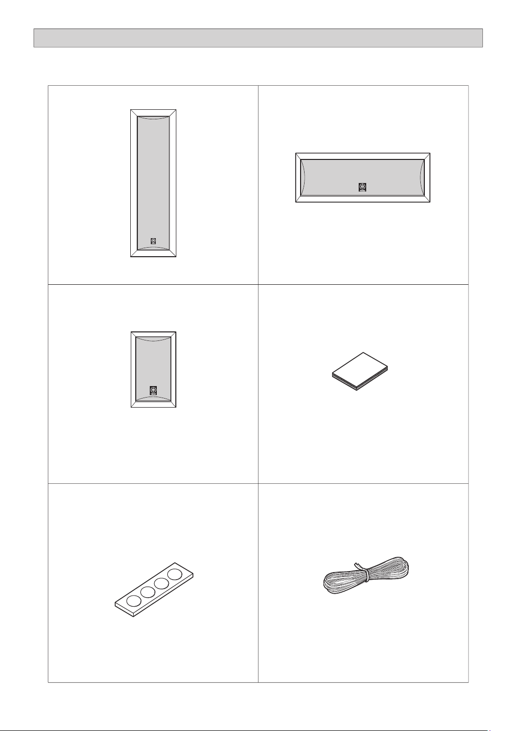
UNPACKING
After unpacking, check that the following items are contained.
Front speakers x 2
(NS-AP9500S)
Surround speakers x 2
Center speaker x 1
(NS-AP9600C)
Fasteners for the center speaker x 2
(NS-AP9600S)
Non-skid pads for Surround speakers x 2 Speaker cable x 1
3
Page 4

SETTING UP THE SPEAKERS
Stand mounting the front speakers
You can use the supplied speaker stands SPS-9500T for table top installation.
For assembly instructions, please refer to the SPS-9500T owner’s manual
which can be found in the SPS-9500T box.
Wall mounting the front speakers
The front speakers may also be hung on a wall, utilizing the key holes on the rear of the speakers.
* Do not use this screw hole.
The screw holes are designed
specifically for use with the inch
screws supplied with the SPS-9500T
speaker stands.
Use the key hole
Use the key hole
Wall / wall support
Tapping screw
(Available at the
hardware store)
*a
*b
*a: Min 1-1/2” (38 mm)
*b: 7/32” (5.5 mm)
Screw
diameter
1/8”-3/16”
(4-4.5 mm)
Fasten screws into a firm wall or wall support as shown in the figure, and hang the holes of the rear of the
speaker on the protruding screws.
Make sure that the screws are securely caught by the narrow sections of the “key hole” opening.
WARNING
The front speakers weigh 7.92 lbs (3.6 kg) each. Do not mount them on thin plywood or a wall with soft
surface material. If mounted, the screws may come out of the flimsy surface and the speakers may fall.
This will damage the speakers and can cause personal injury.
Do not fasten the speaker to a wall with nails, adhesives, or any other unstable hardware. Long-term use
and vibrations may cause them to fall.
To avoid accidents resulting from tripping over loose speaker cords, they should be affixed to the wall or
floor molding.
4
Secure installation is the purchaser’s responsibility.
Page 5

Attaching the non-skid pads to the surround speakers
Place the satellite speakers on a sturdy, vibration-free surface, such as a well-built stand. Attach the included
non-skid pads to the bottom of the surround speakers to prevent the speakers from slipping.
Non-skid pads
Wall mounting the surround speakers
You can also use the screw
Wall / wall support
holes on the back of the
speaker for installing the
speakers on commercially
available speaker brackets.
4-1/2”
(115 mm)
2-3/8”
(60 mm)
A screw with a diameter of
1/4” can be used.
3/8”
Tapping screw
(Available at
the hardware store)
(Hole depth: 9/32”)
When using speaker brackets to mount the speakers on a wall or ceiling, it is strongly recommended that
safety wire, which may be included with the bracket, be used between the speaker and the bracket to prevent
the speaker from falling.
Fasten screws into a firm wall or wall support as shown in the figure, and hang the holes of the mounting
bracket on the protruding screws.
Make sure that the screws are securely caught by the narrow sections of the “key hole” opening.
WARNING
The surround speakers weigh 1.8 lbs. (0.8 kg.) each. Do not mount the speakers on thin plywood or a wall
with soft surface material, since the screws may pull away from the surface and fall. This will damage the
speakers and can cause personal injury.
Do not mount the speakers on a wall with nails, adhesives, or any other unstable hardware. Long-term
use and vibrations may cause them to fall.
To avoid accidents resulting from tripping over loose speaker cords, they should be affixed to the wall or
floor molding.
Secure installation is the purchaser’s responsibility.
Min
1”
5
Page 6

Positioning the center speaker
Place the center speaker on top of the TV, on the floor in front of the TV, or inside the TV rack so that it is stable.
When placing the speaker on top of the TV, put the provided fasteners at four points on both the bottom of the
speaker and on top of the TV to prevent the speaker from falling.
Speaker on top of the TV
TV set
Speaker inside
Fasteners
the TV rack
1
Notes
Do not place the speaker on top of the TV if the area is smaller than the bottom area of the speaker. The
speaker may fall and might cause personal injury.
Though this speaker is magnetically shielded, there may be some influence on a TV picture depending on
the type of TV or the placement of the speaker. In such a case, place the speaker apart from the TV so that
there is no influence on the TV picture.
Wall mounting the center speaker
2-3/8” (60 mm)
7-7/8” (200 mm)
When using speaker brackets to mount the speakers on a wall or ceiling, it is strongly recommended
that safety wire, which may be included with the bracket, be used between the speaker and the
bracket to prevent the speaker from falling.
You can also use the screw holes on
the back of the speaker for installing
the speakers on commercially
available speaker brackets.
A screw with a diameter of 1/4” can be
used
(Hole depth: 9/32”)
Tapping screw
(Available at the hardware store)
Min
1”
3/8”
Wall / wall support
2
Fasten screws into a firm wall or wall support as shown in the figure, and hang the holes of the mounting
bracket on the protruding screws.
Make sure that the screws are securely caught by the narrow sections of the “key hole” opening.
WARNING
The center speaker weighs 3.5 lbs (1.6 kg). Do not mount the speaker on thin plywood or a wall with soft
surface material, since the screws may pull away from the surface and fall. This will damage the speaker
and can cause personal injury.
Do not install the speaker to a wall with nails, adhesives, or any other unstable hardware. Long-term use
and vibrations may cause them to fall.
To avoid accidents resulting from tripping over loose speaker cords, they should be affixed to the wall or
floor molding.
Secure installation is the purchaser’s responsibility.
6
Page 7

CONNECTIONS TO THE RECEIVER
CONNECTIONS
Check to make sure that the receiver has been turned off before making any speaker connections.
Connect the (+) terminal of the receiver to the (+) terminal of the speaker.
Connect the (–) terminal of the receiver to the (–) terminal of the speaker.
Reversing polarity (+/–) will result in unnatural sound reproduction.
PROCEDURE
For connections, keep the speaker cords as short as possible. Do not bundle or roll up the excess part of the
cords. If the connections are faulty, no sound will be heard from the speakers. Make sure that the + and – polarity
markings of the speaker cords are observed and set correctly. If these cords are reversed, the sound will be
unnatural and lack bass.
How to Connect:
Front and Center speakers
1 Loosen the knob.
2 Insert the bare wire. Remove the insulation
coating at the extremity of each speaker cable
by twisting the coating off.
3 Tighten the knob and secure the cable. Test the
firmness of the connection by pulling lightly on the
cable at the terminal.
Loosen
1
Tighten
3
Black (–)
(–) (+)
Surround speakers
2
Red (+)
1 Press and hold the terminal’s tab.
2 Insert the bare wire into the terminal hole. Remove the insulation
coating at the extremity of each speaker cable by twisting the
coating off.
3 Release your finger from the tab to allow it to lock securely on the
bare wire end.
4 Test the firmness of the connection by pulling lightly on the cord at
the terminal.
When using a banana plug
1 Remove the cover by pulling it toward you.
2 Tighten the terminal knob.
3 Insert the banana plug into the terminal.
1
Banana plug
3
2
1 3
2
Note
Do not let the bare speaker wires touch each other as this could damage the speaker, the amplifier, or both.
7
Page 8

SPEAKER PLACEMENT
This speaker system consists of front, center and surround speakers.
— Front speaker placement should be separated by a distance of 6–10ft. If they are placed too close together,
there will be a reduction in the stereo effect. Conversely, If placed too for apart, the so called “middleomission” effect will occur and the vocal center fill will be lost. Height of the speaker should be at least at ear
level.
— Center channel speaker should be placed centered above or below the TV.
— Surround speakers should ideally be placed behind the listening area, at least as far apart as the front
speakers and up to 2 additional feet apart per side. The height of the speaker should be at a minimum of ear
level or preferably somewhat higher.
Center Speaker
Left Front Speaker Right Front Speaker
–
10 feet
6
up to approx
2 feet more
LISTENING AREA
up to approx
2 feet more
Left Surround Speaker Right Surround Speaker
REMOVING THE FRONT GRILL
The speakers have protective grills which can be removed if necessary.
To remove the NS-AP9500S front speaker grill, hold on both sides of the grill
and slowly pull straight away from the speaker. To remove the NS-AP9600C
center and NS-AP9600S surround speaker grill, hold the speaker with one
hand, and pull the grill gently with the other.
8
NS-AP9600SNS-AP9600CNS-AP9500S
Page 9

SPECIFICATIONS
Type Acoustic suspension
Speaker
Front Quad 4” High Compliance Pulp cone and Rubber Surround + 3/4” soft dome tweeter
Center 3” woofer x 2 + 3/4” soft dome tweeter
Surround 3” woofer x 1+ 1/2” balanced dome tweeter
Frequency Range
Front 100 Hz - 40,000 Hz
Center 110 Hz - 40,000 Hz
Surround 110 Hz - 40,000 Hz
Impedance 6 ohms
Nominal Input
Front 35 W
Center 30 W
Surround 30 W
Maximum Input
Front 120 W
Center 100 W
Surround 100 W
Sensitivity (dB/2.83v. 1m)
Front 83 dB
Center 82 dB
Surround 82 dB
Crossover Frequency
Front 600 Hz, 6,000 Hz
Center 5,000 Hz
Surround 5,000 Hz
Dimension (H x W x D)
Front 7-3/8” x 23-27/32” x 3-15/16” (187 x 605 x 99 mm)
Center 4-3/8” x 14-5/8” x 4-3/8” (110 x 370 x 110 mm)
Surround 8-1/2” x 5-1/8” x 4-3/8” (215 x 130 x 110 mm)
Weight
Front 7.9 lbs (3.6 kg)
Center 3.5 lbs (1.6 kg)
Surround 1.8 lbs (0.8 kg)
Magnetic Shielding Ye s
9
Page 10

YAMAHA ELECTRONICS CORPORATION, USA
6660 ORANGETHORPE AVE.,
BUENA PARK, CA 90620
http://www.yamaha.com/yec
Phone: 1-800-492-6242
P/N 430042
Printed in China
 Loading...