

Page 1
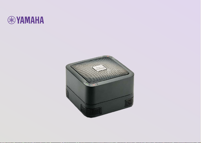
FLX™ UC 500
USB Conference Phone
Quick Start Guide
Putt
ing the Speaker in Speaker pho n e
Page 2

Connecting Your UC 500
Contents
1. Remove UC 500, AC adapter, and USB cable from
box.
2. Connect the appropriate plug clip to the AC adapter.
3. Connect one end of the USB cable to your computer,
and the other end to the connector
on the bottom of the UC 500.
4. Connect the AC adapter to the power connector labelled DC 15V on the bottom of the
UC 500 and the other end to a power source.
5. When booting up, the LEDs on the UC 500 will change between red, green, and amber
lights. When the UC 500 is ready to use, the LEDs will display solid green lights and the
device will emit a chime.
6. For call control functionality of supported applications on your computer, download and
install the FLX UC Device Manager from:
https://uc.yamaha.com/resources/support/
For full documentation, please visit: https://uc.yamaha.com/resources/support/
• 1 FLX UC 500 Base Unit
• 1 USB Cable
• AC Power Adapter
• Plug Clip(s)
Page 3
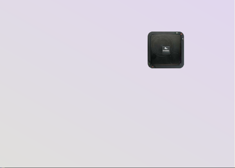
Key Operations
1. Device Volume: The volume output from
the UC 500 is dependent on the
computer volume and device volume up
and down cap touch buttons. Volume is
Volume Up
Mute
Volume Down
increased using the cap-touch button on
the top left of the device. Touch this icon
on the base unit or touch and hold to
increase the volume. A tone will play to
indicate the volume level as it increases.
A double tone will play once maximum
Accept Call
Hang Up Call
volume is reached. Volume is decreased
using the button on the top right of the device. Touch this icon on the base unit or touch and hold to
decrease the volume. A tone will play to indicate the volume level as it is being decreased. A
double tone will play once minimum volume is reached.
2. Mute/Unmute: The microphones will be muted when this button is touched. Press the button again
to unmute. Red LEDs indicate muted microphones. Green LEDs indicate unmuted microphones.
3. Accept Call: To accept a call from the unit, touch this button.*
4. Hang Up Call: To hang up a call from the unit, touch this button.*
*Accept Call & Hang Up Call button functionality only available for use with compatible software
configured with the Revolabs FLX UC Device Manager: Refer to Item 6 in the Connecting your UC 500
section for instructions on how to download the software application.
Page 4

Safety Warnings
• Do not expose any of the UC 500 components to:
• Water, moisture, or hig h humi dity.
• Extreme high or low temperatu r es.
• Lit candles, cigarettes, cigars, or to open flames, etc.
• Do not drop, throw, or try to bend any of the components, as rough treatment could
damage them.
• Do not open the casings of any of the components of the UC 500.
• Only use Revolabs original accessories intended for use with this product to power the
UC 500. Use of non-original accessories may result in loss of performance, damage to
the product, fire, electric shock or injury.
• The warranty does not cover product failures that have been caused by use of non-
original accessories.
• Only use the power adapters provided to connect the components to the power outlet.
Copyright 2018 Yamaha Unified Communications, Inc.
 Loading...