

Page 1
Owner’s Manual
EN
DIGITAL MIXING CONSOLE
Page 2

2
DM7 Console Owner’s Manual
Page 3
Contents
PRECAUTIONS 4
Introduction 8
Intended User ........................................................................................................................................................................ 8
Intended Usage ..................................................................................................................................................................... 8
Accessories ........................................................................................................................................................................... 8
About the Models................................................................................................................................................................... 8
Utility Software....................................................................................................................................................................... 9
Firmware Updates ................................................................................................................................................................. 9
Available Documentation....................................................................................................................................................... 9
Notational Conventions ......................................................................................................................................................... 9
Controls and Functions 10
Top Panel ............................................................................................................................................................................ 10
Rear Panel........................................................................................................................................................................... 12
Front Panel .......................................................................................................................................................................... 14
Touch Screens 15
Viewing Touch Screens ....................................................................................................................................................... 15
Basic Touch Screen Operations.......................................................................................................................................... 15
Installing Optional Cards 16
Installing a PY Card ............................................................................................................................................................. 16
Removing the PY Card........................................................................................................................................................ 16
Setting the Internal Clock 17
Restoring the Factory Settings (Initialization) 17
Installing the Cable Hook 17
Installing the Rack Mount Kit (DM7 COMPACT) 18
Appendix 19
General Specifications......................................................................................................................................................... 19
Dimensions.......................................................................................................................................................................... 20
Source Code Distribution..................................................................................................................................................... 21
DM7 Console Owner’s Manual
3
Page 4
PA_en_13 1/2
PRECAUTIONS
PLEASE READ CAREFULLY
BEFORE PROCEEDING
Please keep this manual in a safe place for
future reference.
WARNING
Always follow the basic precautions listed below to avoid
the possibility of serious injury or even death from
electrical shock, short-circuiting, damages, fire or other
hazards. These precautions include, but are not limited
to, the following:
If you notice any abnormality
• If any of the following problems occur, immediately turn off the
power switch and disconnect the electric plug from the outlet.
- The power cord or plug becomes frayed or damaged.
- Unusual smells or smoke are emitted.
- Some object, or water has been dropped into the product.
- There is a sudden loss of sound during use of the product.
- Cracks or other visible damage appear on the product.
Then have the product inspected or repaired by qualified
Yamaha service personnel.
Power supply
• Do not place the power cord near heat sources such as
heaters or radiators, and do not excessively bend or otherwise
damage the cord, place heavy objects on it, or place it in a
position where anyone could walk on, trip over, or roll anything
over it.
• Only use the voltage specified as correct for the product. The
required voltage is printed on the name plate of the product.
• Use the supplied power cord/plug only.
If you intend to use the product in an area other than in the
one you purchased, the included power cord may not be
compatible. Please check with your Yamaha dealer.
• Do not use the supplied cord/plug for other products.
• Check the electric plug periodically and remove any dirt or
dust which may have accumulated on it.
• Make sure to fully insert the electric plug to prevent electric
shocks or fire.
• This product receives power from multi sources. When setting
up the product, make sure that the AC outlet you
are using is easily accessible. If some trouble or
malfunction occurs, immediately turn off the power
switch and disconnect all plugs from the outlet.
Even when the power switch is turned off, as long
as the power cord is not unplugged from the wall
AC outlet, the product will not be disconnected
from the power source.
• Remove the electric plug from the outlet when the product is
not to be used for extended periods of time.
• Do not touch the product or the electric plug during an
electrical storm.
Connections
• Be sure to connect to an appropriate outlet with a protective
grounding connection. Improper grounding can result in
electrical shock, fire, or damage.
• Always read the manuals of the devices to be connected and
follow the directions they contain. Failure to do so may result in
fire, overheating, explosion, or malfunction.
Do not open
• This product contains no user-serviceable parts. Do not
attempt to disassemble the internal parts or modify them in
any way.
Water warning
• Do not expose the product to rain, use it near water or in
damp or wet conditions, or place on it any containers (such as
vases, bottles or glasses) containing liquids which might spill
into any openings.
• Never insert or remove an electric plug with wet hands.
Fire warning
• Do not place any burning items or open flames near the
product, since they may cause a fire.
Hearing loss
• Before turning the power of all devices on or off, make sure
that all volume levels are set to the minimum. Failing to do so
may result in hearing loss, electric shock, or device damage.
• When turning on the AC power in your audio system, always
turn on the power amplifier LAST, to avoid hearing loss and
speaker damage. When turning the power off, the power
amplifier should be turned off FIRST for the same reason.
• Do not use headphones for a long period of time at a high or
uncomfortable volume level, since this can cause permanent
hearing loss. If you experience any hearing loss or ringing in
the ears, consult a physician.
4
DM7 Console Owner’s Manual
Page 5
PA_en_13 2/2
CAUTION
Always follow the basic precautions listed below to avoid
the possibility of physical injury to you or others. These
precautions include, but are not limited to, the following:
Power supply
• When removing the electric plug from the product or an outlet,
always hold the plug itself and not the cord. Pulling by the
cord can damage it.
Location and connection
• Do not place the product in an unstable position or a location
with excessive vibration, where it might accidentally fall over
and cause injury.
• Keep this product out of reach of children. This product is not
suitable for use in locations where children are likely to be
present.
• Do not block the vents. This product has ventilation holes at
the front/rear to prevent the internal temperature from
becoming too high. In particular, do not place the product on
its side or upside down. Inadequate ventilation can result in
overheating, possibly causing damage to the product(s), or
even fire.
• [DM7 COMPACT] If the product is mounted in an EIA standard
rack, carefully read the section “Precautions for rack
mounting” on page 18. Inadequate ventilation can result in
overheating, possibly causing damage to the product(s),
malfunction, or even fire.
• Do not place the product in a location where it may come into
contact with corrosive gases or salt air. Doing so may result in
malfunction.
• Before moving the product, remove all connected cables.
• [DM7] When transporting or moving the product, always use
two or more people. Attempting to lift the product by yourself
may result in injuries, such as back injuries, or cause the
product to be dropped and broken, which could lead to other
injuries.
NOTICE
To avoid the possibility of malfunction/damage
to the product, damage to data, or damage to
other property, follow the notices below.
Handling and maintenance
• Do not connect this product to public Wi-Fi and/or Internet
directly. Only connect this product to the Internet through a
router with strong password-protections. Consult your router
manufacturer for information on security best practices.
• Do not use the product in the vicinity of a TV, radio, or other
electric products. Otherwise, the product, TV, or radio may
generate noise.
• Do not expose the product to excessive dust or vibration, or
extreme cold or heat, in order to prevent the possibility of
panel disfiguration, unstable operation, or damage to the
internal components.
• Do not install in locations where temperature changes are
severe. Otherwise, condensation may form on the inside or
the surface of the product, causing it to break.
• If there is reason to believe that condensation might have
occurred, leave the product for several hours without turning
on the power until the condensation has completely dried out,
in order to prevent possible damage.
• Do not place vinyl, plastic or rubber objects on the product,
since this might cause alteration or discoloration of the panel.
• Clean the product with a dry and soft cloth. Do not wipe
product surfaces with sodium hypochlorite, alcohol, benzene,
paint thinners, cleaning fluids, or a chemical-impregnated
wiping cloth, which could cause discoloration or change
surface characteristics.
• Do not apply oil, grease, or contact cleaner to the faders.
Doing so might cause problems with electrical contact or
fader motion.
Maintenance
• Remove the power plug from the AC outlet when cleaning the
product.
Handling caution
• Do not rest your weight on the product or place heavy objects
on it.
Internal battery for clock display
• Do not replace the internal battery by yourself. Doing so may
cause an explosion and/or damage to the product(s).
When the internal battery needs to be replaced, “Low Battery”
or “No Battery” will appear on the display. In this case, contact
your Yamaha dealer and have qualified Yamaha service
personnel replace the internal battery.
DM7 Console Owner’s Manual
5
Page 6
Information
About copyrights
• Copying of the software or reproduction of this manual in
whole or in part by any means is expressly forbidden without
the written consent of the manufacturer.
• Copying of commercially available musical data including but
not limited to MIDI data and/or audio data is strictly prohibited
except for your personal use.
Protection of copyright
About disposal
• This product contains recyclable components.
When disposing of this product, please contact the
appropriate local authorities.
Yamaha cannot be held responsible for damage caused by
improper use or modifications to the product, or data that is
lost or destroyed.
• Do not use this product for any purpose that may infringe
upon the rights of any third party including copyrights, as
established by law in each country or region.
• Yamaha bears no responsibility for any infringement upon
third party rights that may occur as a result of using this
product.
About functions/data bundled with the product
• This product uses Dante IP Core and Dante API for ARM.
Refer to the Audinate website (English) for details on the
open-source licenses for the particular software.
https://www.audinate.com/software-licensing
• The open source license used with this product can be
checked on the screen of the unit. For more details, refer to
the DM7 series Reference Manual.
• XLR-type connectors are wired as follows (IEC60268 standard):
pin 1: ground, pin 2: hot (+), and pin 3: cold (−).
About this manual
• The illustrations and screens as shown in this manual are for
instructional purposes only.
• Steinberg Media Technologies GmbH and Yamaha
Corporation make no representations or warranties with
regard to the use of the software and documentation and
cannot be held responsible for the results of the use of this
manual and the software.
• The company names and product names in this manual are
the trademarks or registered trademarks of their respective
companies.
• Steinberg and Nuendo are registered trademarks of Steinberg
Media Technologies GmbH.
• Windows is a registered trademark of Microsoft Corporation in
the United States and other countries.
• Apple, Mac, and iPad are trademarks of Apple Inc. registered
in the United States and other countries.
• IOS is a trademark or registered trademark of Cisco in the U.S.
and other countries and is used under license.
• The typefaces included herein are solely developed by
DynaComware Taiwan Inc.
• Software may be revised and updated without prior notice.
The model number, serial number, power requirements, etc.,
may be found on or near the name plate, which is at the
bottom of the unit (DM7 COMPACT).
You should note this serial number in the space provided
below and retain this manual as a permanent record of your
purchase to aid identification in the event of theft.
Model No.
Serial No.
(1003-M06 plate bottom en 01)
6
DM7 Console Owner’s Manual
Page 7
FCC INFORMATION (U.S.A.)
1. IMPORTANT NOTICE: DO NOT MODIFY THIS UNIT!
This product, when installed as indicated in the instructions contained in this manual, meets FCC requirements. Modifications not
expressly approved by Yamaha may void your authority, granted by the FCC, to use the product.
2. IMPORTANT: When connecting this product to accessories and/or another product use only high quality shielded cables. Cable/s
supplied with this product MUST be used. Follow all installation instructions. Failure to follow instructions could void your FCC
authorization to use this product in the USA.
3. NOTE: This product has been tested and found to comply with the requirements listed in FCC Regulations, Part 15 for Class “B” digital
devices. Compliance with these requirements provides a reasonable level of assurance that your use of this product in a residential
environment will not result in harmful interference with other electronic devices. This equipment generates/uses radio frequencies and, if
not installed and used according to the instructions found in the users manual, may cause interference harmful to the operation of other
electronic devices. Compliance with FCC regulations does not guarantee that interference will not occur in all installations. If this product
is found to be the source of interference, which can be determined by turning the unit “OFF” and “ON”, please try to eliminate the problem
by using one of the following measures:
- Relocate either this product or the device that is being affected by the interference.
- Utilize power outlets that are on different branch (circuit breaker or fuse) circuits or install AC line filter/s.
- In the case of radio or TV interference, relocate/reorient the antenna. If the antenna lead-in is 300 ohm ribbon lead, change the lead-in
to co-axial type cable.
If these corrective measures do not produce satisfactory results, please contact the local retailer authorized to distribute this type of
product. If you cannot locate the appropriate retailer, please contact Yamaha Corporation of America, 6600 Orangethorpe Avenue, Buena
Park, CA 90620, U.S.A.
The above statements apply ONLY to those products distributed by Yamaha Corporation of America or its subsidiaries.
(529-M04 FCC class B YCA 02)
COMPLIANCE INFORMATION STATEMENT
(Supplier’s declaration of conformity procedure)
Responsible Party: Yamaha Corporation of America
Address: 6600 Orangethorpe Avenue, Buena Park, CA.
90620, U.S.A.
Telephone: 714-522-9011
Type of Equipment: Digital Mixing Console
Model Name: DM7, DM7C
This device complies with Part 15 of the FCC Rules.
Operation is subject to the following two conditions:
1) this device may not cause harmful interference, and
2) this device must accept any interference received, including
interference that may cause undesired operation.
(529-M02 FCC sdoc YCA 02)
Information for users on collection and disposal of old equipment:
This symbol on the products, packaging, and/or accompanying documents means that used electrical and electronic products
should not be mixed with general household waste.
For proper treatment, recovery and recycling of old products, please take them to applicable collection points, in accordance
with your national legislation.
By disposing of these products correctly, you will help to save valuable resources and prevent any potential negative effects on
human health and the environment which could otherwise arise from inappropriate waste handling.
For more information about collection and recycling of old products, please contact your local municipality, your waste disposal
service or the point of sale where you purchased the items.
For business users in the European Union:
If you wish to discard electrical and electronic equipment, please contact your dealer or supplier for further information.
Information on Disposal in other Countries outside the European Union:
This symbol is only valid in the European Union. If you wish to discard these items, please contact your local authorities or
dealer and ask for the correct method of disposal.
This product contains a battery that contains perchlorate
material.
Perchlorate Material - special handling may apply.
See www.dtsc.ca.gov/hazardouswaste/perchlorate
(583-M01 percholorate 01)
(58-M02 WEEE en 01)
DM7 Console Owner’s Manual
7
Page 8
Introduction
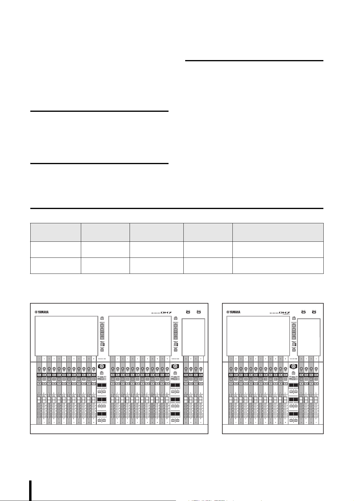
DM7 DM7 COMPACT
Thank you for your purchase of the Yamaha DM7 or DM7
COMPACT. To take full advantage of the product’s
functionality, please read this manual before you begin
using the product. Afterwards, please keep the manual in a
safe place.
Intended User
This product is designed for individuals who are capable of
operating a mixing console for use with a PA system in
concert halls, at musical events, or in recording studios.
Accessories
• Power cord × 2
(Multiple AC power cords which have different kinds of
plug shapes may be included depending on the region.)
•Dust cover × 1
(If this product is connected to a separately-sold DM7
CONTROL (CTL-DM7), open both zippers on the dust
cover and extend it to cover both units.)
• Cable hook × 1
• Nuendo Live and VST Rack Elements Download
Information leaflet
• Owner’s Manual (this book)
Intended Usage
This product is designed for mixing operations in concert
halls, at musical events, broadcasting, or audio productions.
About the Models
Differences between the DM7 and DM7 COMPACT are summarized in the table below.
Number of
Analog Inputs
DM7 32 120 4-in/4-out Channel Strip section: 24
DM7 COMPACT 16 72 0-in/2-out Channel Strip section: 12
Number of Monaural
Input Channels
AES/EBU Channel Strips
Main section: 4
Main section: 4
NOTE
Unless otherwise noted, illustrations in this manual are of the DM7.
8
DM7 Console Owner’s Manual
Page 9
Utility Software
Available Documentation
The DM7 and DM7 COMPACT can be used with a variety
of utility software.
For information regarding how to download or install the
software, as well as its various setting details, refer to the
following Yamaha Pro Audio website or to the Installation
Guide attached to the downloaded software program.
https://www.yamahaproaudio.com/
DM7 Editor
This application software enables you to set up and operate
the unit from a connected computer. You can also back up
the unit settings, or set up the unit at a remote site where
access to the unit is limited.
DM7 StageMix
This application software enables you to control the unit
remotely from an iPad.
MonitorMix
This application software enables you to remotely control
the monitor mix balance of any DM7-series unit from a
smart device connected via Wi-Fi.
Console File Converter
This application software enables you to convert settings
file formats between the Yamaha RIVAGE PM series,
CL series, QL series and DM7 series.
ProVisionaire series
This application software enables you to create a control
panel that suits the setup environment or operational
procedure, and to remotely control and monitor devices.
Owner’s Manual (this book)
This book primarily explains panel controls and functions.
DM7 series Reference Manual
This manual provides detailed explanations of all screens
and functions, and includes step-by-step procedures and a
system set-up procedure to help you operate the DM7
series.
https://manual.yamaha.com/pa/mixers/dm7/rm/
DM7 Editor Installation Guide
This guide explains how to install DM7 Editor.
https://manual.yamaha.com/pa/mixers/dm7/ig/
DM7 StageMix User Guide
This guide explains iPad application software that enables
you to control the DM7 series system wirelessly.
https://manual.yamaha.com/pa/mixers/dm7/ug/
Firmware Updates
You can update the unit firmware to improve the operation,
add functions, and correct possible malfunctions.
Information on updating the firmware can be found on the
following website.
https://www.yamahaproaudio.com/
For information on updating and setting up the unit, please
refer to the firmware update guide available on the website.
All of these manuals can be downloaded from the Yamaha
website. If necessary, you can view updated manual
information, which is always posted on the Yamaha website.
https://download.yamaha.com/
Notational Conventions
In this manual, switch-type controllers on the panel are
called “keys.” Names of controls located on the panel are
enclosed in square brackets [ ] (e.g., [HOME]) to distinguish
them from virtual buttons and knobs displayed on screen.
DM7 Console Owner’s Manual
9
Page 10
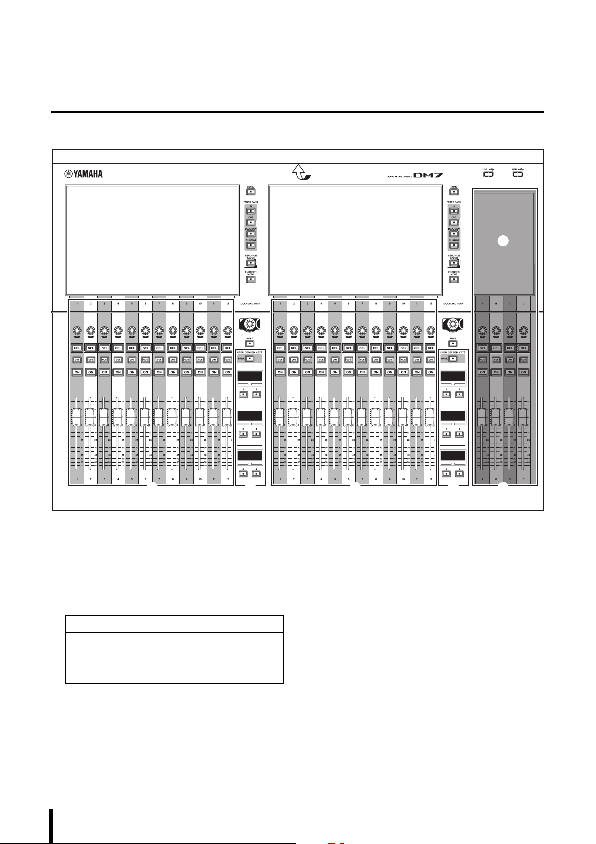
Controls and Functions
1
2
4
3
5
7
B
A
8
6 9
1
6 9 0
1
2
4
3
5
7
8
Top Pan el
1 Touch screens
These are capacitive multi-touch screens. The touch
screens will not respond correctly if you are wearing
gloves.
NOTICE
Never use a sharp or pointed object such as your
fingernail to operate the touch screens. Doing so may
scratch the screens and render the touch screens
inoperable.
(“Viewing Touch Screens” “Basic Touch Screen
Operations” page 15)
NOTE
Before use, be sure to remove the transparent film that
was applied to the touch screens to protect them during
transport.
2 [HOME]
Recall and toggle between the OVERVIEW and
SELECTED CHANNEL VIEW screens.
3 [FADER BANK]
Assign the function to the faders on the panel.
4 [SENDS ON FADER]
Switch SENDS ON FADER mode on or off. When this
mode is turned on, you can use the channel strips to
adjust the send level of signals sent to the MIX/MATRIX
bus.
10
DM7 Console Owner’s Manual
Page 11
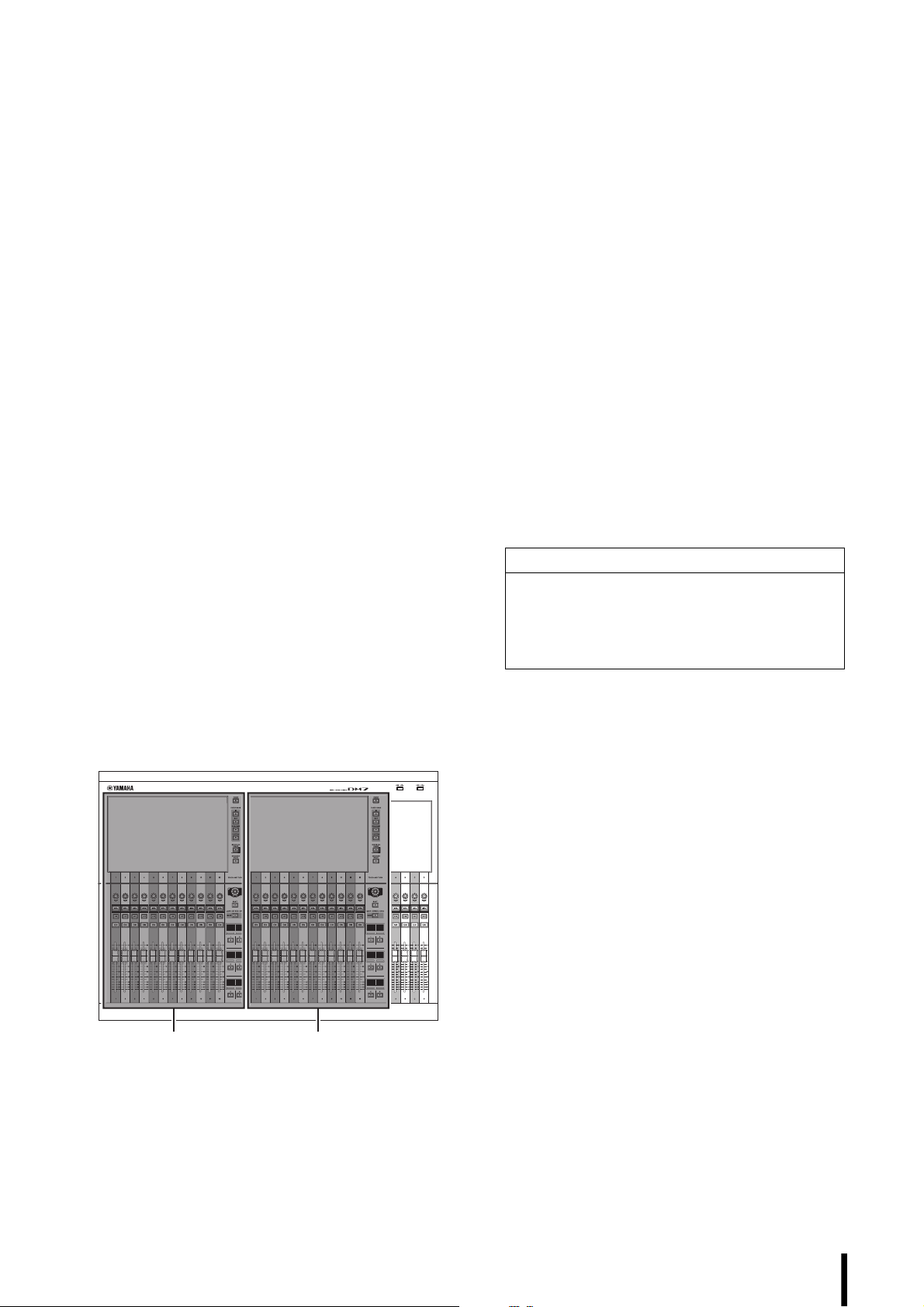
5 [ENCODER MODE]
Bay L
(DM7 only)
Bay C
Use these keys to display the screen on the
corresponding Bay screen to switch between functions
for the encoders located below the touch screen. These
encoders feature the following two functions:
Screen Encoder function
Up to 12 parameters can be assigned to the encoders
via the touch screens.
Channel Encoder function
Parameters for 12 channels on the channel strips can be
assigned to the encoders.
6 Channel Strip sections
Enable you to adjust the main parameters for the
currently-selected channels.
7 [TOUCH AND TURN]
Control the parameter of the knob selected via the touch
screens.
8 [SHIFT]
Combine with another key to perform a certain function.
For more information, refer to the DM7 series Reference
Manual.
9 [USER DEFINED KEYS]
Enable you to control the assigned function. Use the
[BANK] to switch banks.
0 Main section
This section enables you to adjust main parameters for
the assigned channels. By default, STEREO A and
STEREO B are assigned to channel C and D
respectively.
NOTE
The shaded areas in the following illustration are called
Bay L (DM7 only) and Bay C respectively.
A LED lighting bar
Illuminates the operation panel in a dark place. For
more information, refer to the DM7 series Reference
Manual.
B USB connectors
These are USB Type-A connectors.
Use these connectors to connect a USB storage device
such as a USB flash drive.
• Supported USB flash drive format
The FAT16/FAT32 formats are supported.
• Preventing accidental erasure
Some USB flash drives feature write protection that
prevents data from being erased inadvertently. If your
USB flash drive contains important data, we suggest
that you use write protection to prevent accidental
erasure.
On the other hand, you will need to make sure that your
USB flash drive’s write-protect setting is turned off
before you save data onto the flash drive.
For the latest information on what USB flash drives can
be used with the system, visit the Yamaha Pro Audio
website at:
https://www.yamahaproaudio.com/
NOTICE
Do not remove the USB flash drive from the USB
connector or turn off the power to the unit while the unit
is accessing data, e.g., saving, loading or deleting
data. Doing so may damage your flash drive, or may
damage the data in the unit or on your media device.
DM7 Console Owner’s Manual
11
Page 12
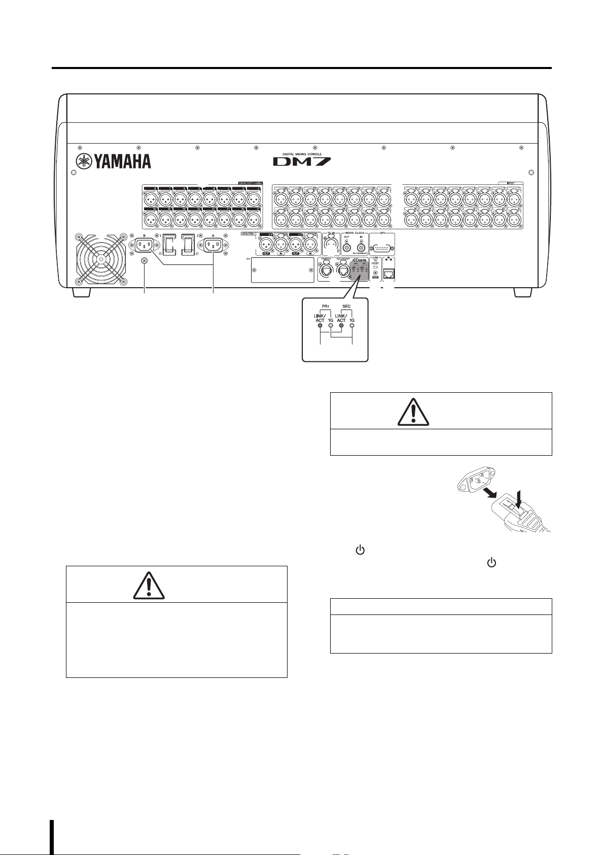
Rear Panel
1 2
3
5
0
A
D
7
98
6
E
F 4
B C
1 [OMNI OUT]
These are balanced XLR 3-pin chassis output
connectors that transmit analog audio signals.
2 [INPUT]
These are balanced XLR 3-hole chassis input
connectors for analog audio signals from line level
devices or microphones.
3 Cooling vent
This product is equipped with a cooling fan. This vent
lets warm air escape from the unit. Make sure that you
do not block the vent with any object. The air is taken in
through the ventilation ports at the rear and under the
front.
CAUTION
Do not block the ventilation ports (heat dissipating slits)
on this product. This product has ventilation ports at
the front and rear to prevent the internal temperature
from becoming too high. If the ventilation ports are
blocked, heat will get trapped inside the product, which
may cause malfunction or fire.
4 AC IN connectors [A]/[B]
Use these sockets to connect the supplied power cords.
First connect the AC power cords to this unit, and then
insert the power cord plugs into AC outlets.
Insert the power cord plugs all the way into the power
connectors until they lock in place securely. The
supplied AC power cords feature a V-lock mechanism
via a latch, which prevents the power cords from
disconnecting accidentally.
CAUTION
Be sure to turn off the power to the unit before
connecting or disconnecting the power cords.
To disconnect each power
cord, remove it while pressing
the latch on the plug.
5 [ I ]/[ ] (Power switches)
Toggle between power on ( I ) and off ( ). If you plan
not to use the unit for a long period of time, remove the
power cords from the AC outlets.
NOTICE
Turning the unit on and off in rapid succession can
cause it to malfunction. After turning the unit off, wait
at least six seconds before turning it on again.
NOTE
• This product will operate normally when one or both
power supplies [A] and [B] are both on.
• If both power supplies are on and one of the power
supplies fails during operation, the unit automatically
switches to the other power supply.
12
DM7 Console Owner’s Manual
Page 13

6 [AES/EBU]
The DM7 is equipped with a sampling rate converter at
both the [IN] and [OUT] chassis connectors. Please
note that the DM7 COMPACT, which features only the
[OUT] chassis connectors, is not equipped with a
sampling rate converter.
[IN] (DM7 only)
These are balanced XLR 3-hole chassis input connectors
that accept digital audio signals in the AES/EBU format.
[OUT]
These are balanced XLR 3-pin chassis output connectors
for digital audio signals in the AES/EBU format.
7 [TC IN]
This balanced XLR 3-hole chassis input connector accepts
time code signals from the connected external device.
8 [WORD CLOCK OUT/IN]
These are BNC sockets used to transmit and receive
word clock signals to and from an external device. The
[WORD CLOCK IN] is internally terminated by a 75 ohm
resistor.
9 [GPI]
This is a D-sub 15-hole chassis connector that allows
communication (5-in/5-out) with a GPI-equipped
external device.
0 [PY]
This card slot enables you to install a separately-sold PY
card to expand the number of I/O ports.
(“Installing Optional Cards” page 16).
A Dante [PRIMARY]/[SECONDARY]
These connectors are used to connect to other Dante
audio network devices, such as an Rio3224-D2 I/O
device. Use RJ-45 plugs that are compatible with
Neutrik etherCON CAT5e connectors.
These connectors support up to 144-in/144-out, and
96 kHz/24 or 32-bit, or 48 kHz/24 or 32-bit audio.
NOTE
• Use STP (Shielded Twisted Pair) cable to prevent
electromagnetic interference. Make sure that the metal
parts of the plugs are electrically connected to the STP
cable shield by conductive tape or comparable means.
• Please do not use the EEE function (*) of network
switches in a Dante network.
Although power management should be negotiated
automatically in switches that support EEE, some
switches do not perform the negotiation properly. This
may cause EEE to be enabled in Dante networks when
it is not appropriate, resulting in poor synchronization
performance and occasional dropouts.
Therefore we strongly recommend that:
- If you use managed switches, ensure that they allow
EEE to be disabled. Make sure that EEE is disabled
on all ports used for real-time Dante traffic.
- If you use unmanaged switches, make sure to not
use network switches that support the EEE function,
since EEE operation cannot be disabled in these
switches.
* EEE (Energy Efficient Ethernet) is a technology that
reduces switch power consumption during periods of
low network traffic. It is also known as Green Ethernet
and IEEE802.3az.
B [LINK/ACT]
These indicators show the communication status of the
[PRIMARY] and [SECONDARY] respectively.
If the Ethernet cables are connected properly, the
indicators will flash rapidly.
C [1G]
These indicators light when the Dante network is
functioning as Giga-bit Ethernet.
D [USB TO HOST]
This is a USB Type-C (USB2.0) connector.
By connecting a computer here via a USB cable, the
console can function as an up to 18-in/18-out,
96 kHz/32-bit or 48 kHz/32-bit audio interface. It also
enables you to use USB-MIDI to control any DM7-series
unit and remotely control DAW software.
You must install the Yamaha Steinberg USB Driver to
communicate with the computer. For more information,
refer to the DM7 series Reference Manual.
NOTICE
• Use USB cables less than three (3) meters long.
• Leave an interval of at least six (6) seconds between
plugging and unplugging the USB cable.
E Network connector
This RJ-45 connector allows the unit to be connected to
a computer via an Ethernet cable (CAT5 or higher
recommended).
You can control the unit from supported application
software, such as DM7 Editor.
NOTE
Use STP (Shielded Twisted Pair) cable to prevent
electromagnetic interference.
F Grounding screw
Each supplied power cord features a three-prong plug.
If the AC outlets are grounded, this product will be
properly grounded through the power cords. Also,
grounding this screw may effectively eliminate noise
such as hum and interference.
DM7 Console Owner’s Manual
13
Page 14
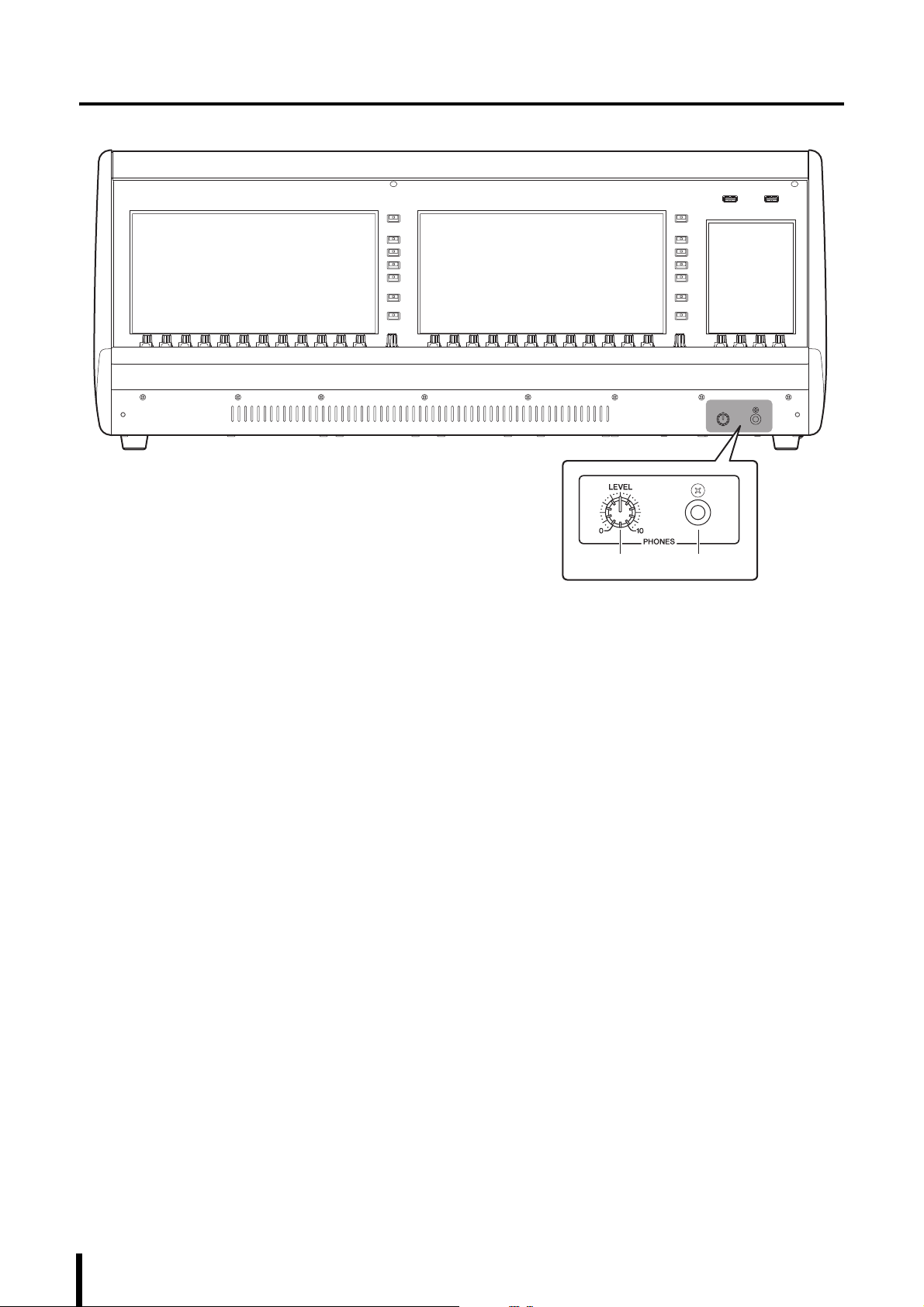
Front Panel
1 2
1 [PHONES LEVEL]
Adjusts the level of the signal output from the PHONES
output socket.
2 [PHONES]
This is a headphone socket for monitoring the
MONITOR or CUE signal.
14
DM7 Console Owner’s Manual
Page 15
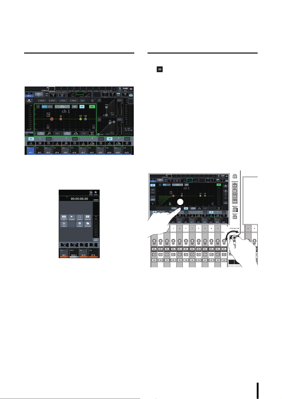
Touch Screens
1
2
[TOUCH AND TURN]
Viewing Touch Screens
Bay screens
These are touch screens for Bay C, and for Bay L (DM7
only). On these screens, you can display various interface
screens using the menu bar to set parameters.
Utility screen
This is a touch screen for the Main section. On this screen,
you can view the status of the unit, and recall other screens
for monitoring or other operational purposes.
Basic Touch Screen Operations
Switching between screens
Tap in the upper-right corner of the Bay screen to
display the menu bar. Tap a desired button on the menu bar
to switch to the corresponding screen.
In the Utility screen, tap the desired button on the HOME
screen to switch to the corresponding screen. Tap the
HOME button to return to the HOME screen.
NOTE
The selected area marked by a pink frame on screen
includes a parameter that can be controlled via the
[TOUCH AND TURN].
Controlling the parameters using the [TOUCH
AND TURN] (
Tap the desired parameter to select it (1), and then use the
[TOUCH AND TURN] to adjust the parameter (
frame appears around the selected parameter.
7 on page 11)
2). A pink
Scrolling
On screens that feature a scroll bar, slide your finger up and
down or left and right to scroll the screen.
Swiping the screen allows you to scroll quickly.
You can also manipulate the screen as follows: For more
information, refer to the DM7 series Reference Manual.
• Pinching or spreading two fingers in and out
You can use this technique to adjust Q for EQ.
• Sliding three fingers up and down
You can use this technique to adjust the amount of
cut/boost of EQ gain for multiple bands simultaneously.
• Sliding four fingers up and down /
Pinching or spreading three fingers in and out
You can use this technique to magnify or reduce the
amount of EQ gain adjustment across multiple bands.
DM7 Console Owner’s Manual
15
Page 16
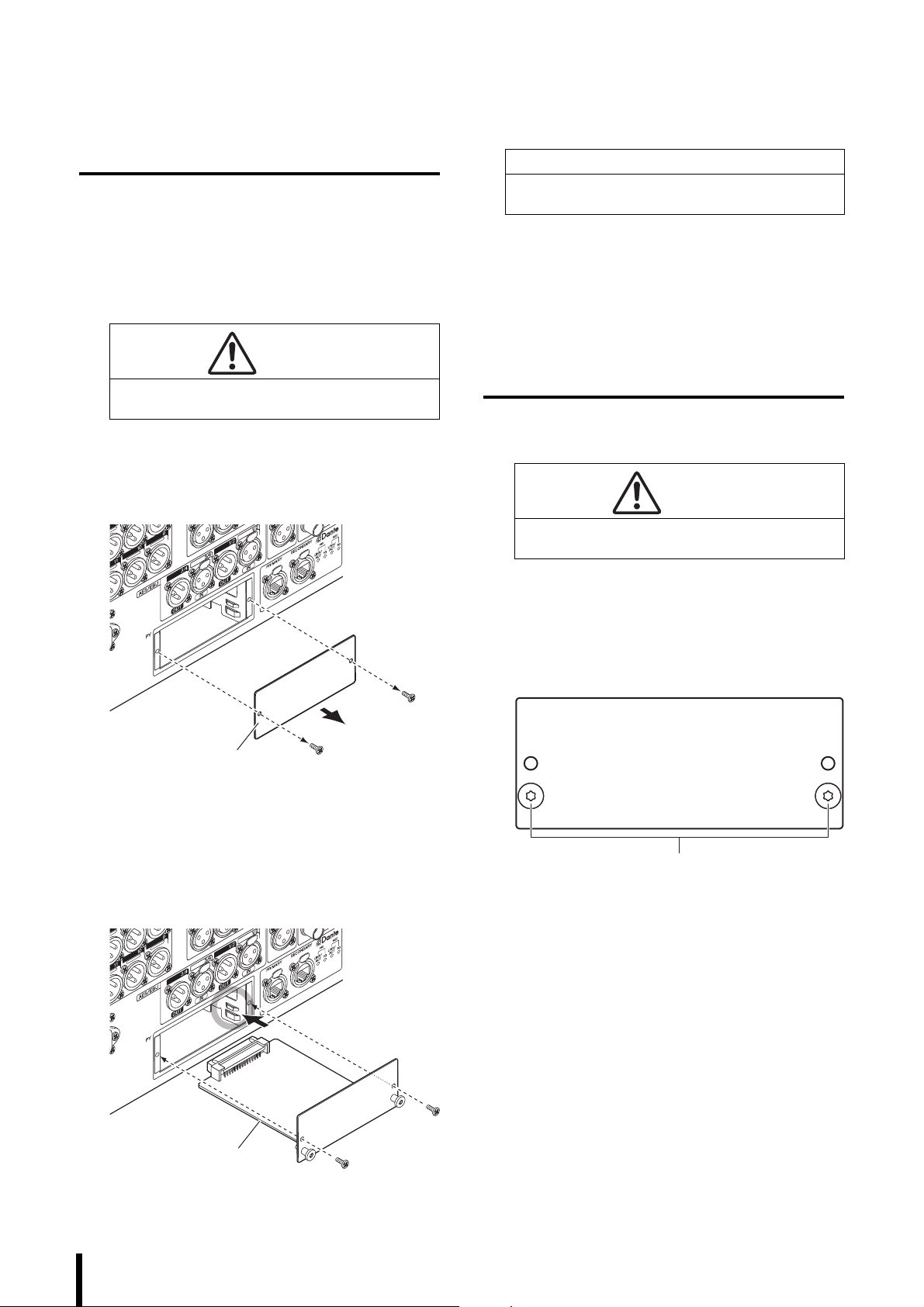
Installing Optional Cards
Slot cover
PY card
Handles
PY card
Installing a PY Card
Before you install a PY card, you must check the Yamaha
Pro Audio global website to see whether the DM7 series
supports your card.
https://www.yamahaproaudio.com/
1. Make sure that the power to this product is
turned off.
CAUTION
Installing or removing a card while the power is on
may lead to component failure or electric shock.
2. Remove the screws that fasten the [PY] slot
cover and remove the cover.
The removed screws will be used again to install the
PY card. Keep the cover in a safe place for future use.
NOTICE
When inserting the PY card, align both sides of the PY
card with the guide rails in the slot of the host device.
4. Affix the PY card using the screws that were
removed in step 2.
Do not use the card unless it is affixed by the screws
securely. Be aware that component failure or
malfunction may occur if the PY card is not fastened.
Removing the PY Card
1. Make sure that the power to this product is
turned off.
CAUTION
Installing or removing a card while the power is on
may lead to component failure or electric shock.
2. Completely loosen and remove the screws
that hold the PY card in place.
3. Align both edges of the PY card with the
guide rails inside the slot, and then insert the
PY card into the slot.
Push the PY card all the way into the slot so that the
connector at the end of the PY card is correctly
inserted into the connector inside the slot.
3. Pull the card toward you while holding the
peg-shaped handles (see the figure below) on
the PY card.
4. Replace the stored slot cover and affix it with
the screws.
Do not use the unit while the slot cover is removed.
Component failure or malfunction may occur.
16
DM7 Console Owner’s Manual
Page 17
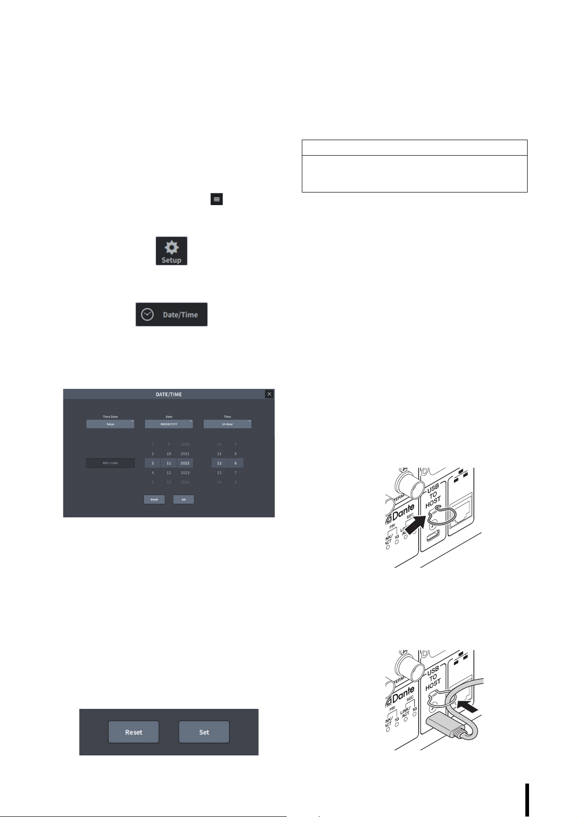
Setting the Internal
Restoring the Factory
Clock
This section explains how to set the date and time of the
clock, and how to select a time zone, and a date and time
display format.
The date and time you specify here will affect the time
stamp used for scenes or when you save or load files.
1. Tap the Setup button on the menu bar on the
right side on the Bay screen.
If the menu bar is not displayed, tap in the
upper-right corner of the screen to display the menu
bar.
2. Tap the Date/Time button.
The DATE/TIME screen appears.
3. In the DATE/TIME screen, select a time zone,
and a date and time display format.
Settings (Initialization)
If an error occurs in the unit’s internal memory, or if you
forget the password and cannot operate the unit, you can
use the following procedure to initialize the internal memory.
NOTICE
When you initialize the internal memory, all content that
had been saved in memory will be erased. Use caution
when performing the following steps.
1. Press and hold down the [SEL] for channel D
in the Main section while turning on the
power to the unit.
2. Once the MAINTENANCE screen opens in the
Utility screen, tap the Initialize All Memory
button.
The system reverts to factory settings.
Installing the Cable
Hook
A cable hook is provided to prevent accidental
disconnection of the USB cable. The hook can be installed
by the following procedure.
You can choose from the following display formats.
Flick numbers to set the date and time.
• Date
MM/DD/YYYY (Month/Day/Year)
DD/MM/YYYY (Day/Month/Year)
YYYY/MM/DD (Year/Month/Day)
• Time
24-Hour (Hours are indicated in the range of 0–23.)
12-Hour (Hours are indicated in the range of
AM0–AM11 and PM0–PM11.)
4. When you finish making settings, tap the Set
button. To revert to the previous date and
time settings, tap the Reset button.
1. Hook one end of the included cable hook
onto one side of the security slot located
above the [USB TO HOST] connector on the
rear panel.
2. Insert the other end of the hook into the other
side of the security slot.
3. Pass the USB cable through the hook and
connect it to the USB connector.
DM7 Console Owner’s Manual
17
Page 18
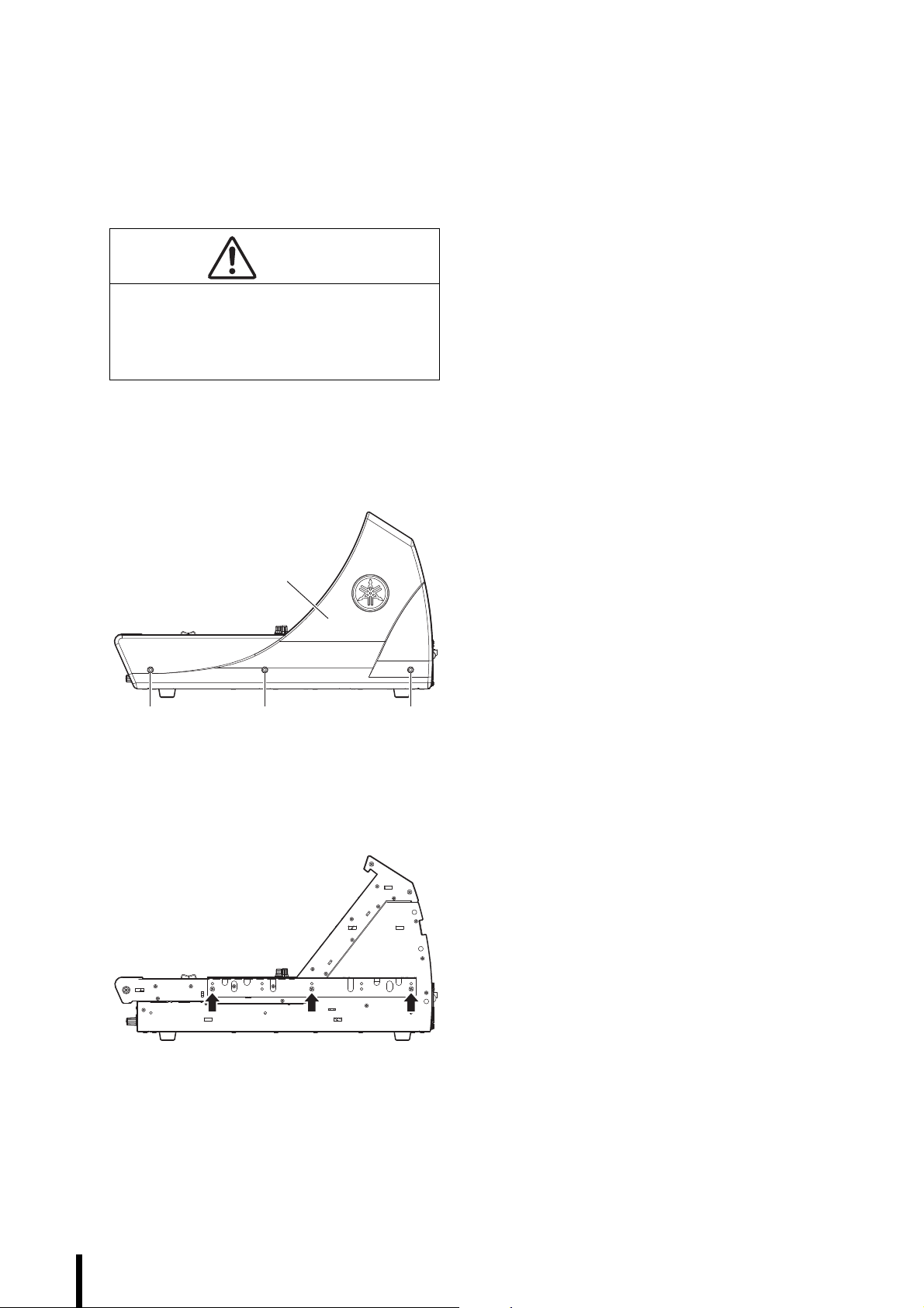
Installing the Rack Mount Kit (DM7 COMPACT)
Side pads
AA A
You can attach the separately-sold RK1 Rack Mount Kit to
the DM7 COMPACT and mount the unit in a rack or in an
installed system.
1. Make sure that the power is turned off.
CAUTION
When attaching the RK1 Rack Mount Kit, you must
turn off the power switches on the unit and use the
screws that are included in the RK1 package.
Otherwise, component failure or electric shock may
occur.
2. Remove screws (A) on the side pads to
detach the pads.
NOTE
Keep the side pad screws together with the pads you
removed.
Precautions for rack mounting
Operation of this device is guaranteed within a temperature
range of 0 to 40°C. If you mount this unit along with other
equipment in an EIA standard rack, the heat from each
device will raise the temperature inside the rack, which may
prevent the unit from achieving full performance. When rack
mounting the unit, always observe the following
requirements to avoid heat buildup:
• Be sure to leave at least 14U space (excluding the space
for cable connections) around the unit.
• When mounting the unit in a rack with devices such as
power amplifiers that tend to generate a significant
amount of heat, leave a sufficient space between this unit
and other equipment. Also, ensure sufficient ventilation
by installing a ventilation panel in these spaces, or simply
leave the open spaces uncovered.
• To ensure sufficient airflow, leave the rear of the rack
open and position it at least 10 cm from walls, ceilings or
other surfaces. If the rear of the rack cannot be left open,
install a commercially-available fan kit or similar forced
system to secure sufficient airflow. If you have installed a
fan kit, there may be cases in which closing the rear of the
rack will produce a greater cooling effect. For more
information, refer to the instruction manuals for the rack
and fan kit.
3. Use the screws included in the RK1 package
to install the hardware.
Tighten the screws at three locations as indicated by
the arrows in the illustration below.
4. Attach the hardware to the other side in the
same way.
18
DM7 Console Owner’s Manual
Page 19
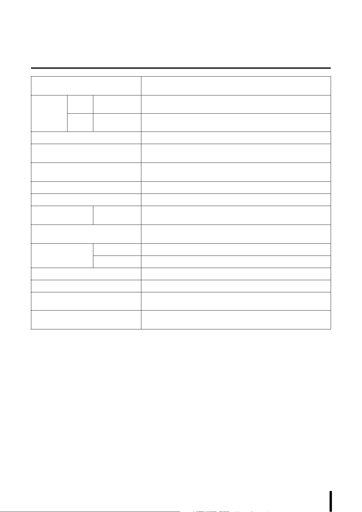
Appendix
General Specifications
Mixing Capacity DM7: 120 Inputs, 48 MIX + 12 MATRIX + 2 STEREO
DM7 COMPACT: 72 Inputs, 48 MIX + 12 MATRIX + 2 STEREO
Sampling
Frequency
Signal Delay Less than 1.5 ms, INPUT to OMNI OUT @Fs=96 kHz
Screen DM7: 12.1" multi-touch screen × 2, 7" multi-touch screen × 1
Fader DM7: 100 mm touch-sensitive motorized fader × 28
Power Requirements 100-240 V, 50/60 Hz
Power Consumption 240 W
Dimensions W × H × D DM7: 793 mm × 324 mm × 564 mm (including the rubber feet)
Weight DM7: 23.5 kg
NC Value
Operating Temperature Range Min: 0°C, Max: 40°C
*1
External
Clock
Internal
Clock
Frequency Range 48 kHz / 96 kHz ±200 ppm
Frequ ency 48 kHz / 96 kHz
DM7 COMPACT: 12.1" multi-touch screen × 1, 7" multi-touch screen × 1
DM7 COMPACT: 100 mm touch-sensitive motorized fader × 16
DM7 COMPACT: 468 mm × 324 mm × 564 mm (including the rubber feet)
DM7 COMPACT: 16.5 kg
Fan Speed LOW NC=20
Fan Speed HIGH NC=30
Storage Temperature Range Min: −20°C, Max: 60°C
Accessories Owner’s Manual, AC power cord ×2, Dust cover, Cable hook, Nuendo Live and VST
Rack Elements Download Information leaflet
Optional Items DM7: PY cards, DM7 CONTROL (CTL-DM7)
DM7 COMPACT: PY cards, DM7 CONTROL (CTL-DM7), Rack Mount Kit RK1
*1. Measured 30 cm horizontally away and vertically up from the unit (front pad).
The contents of this manual apply to the latest specifications as of the publishing date. To obtain the latest manual, access the
Yamaha website then download the manual file.
DM7 Console Owner’s Manual
19
Page 20
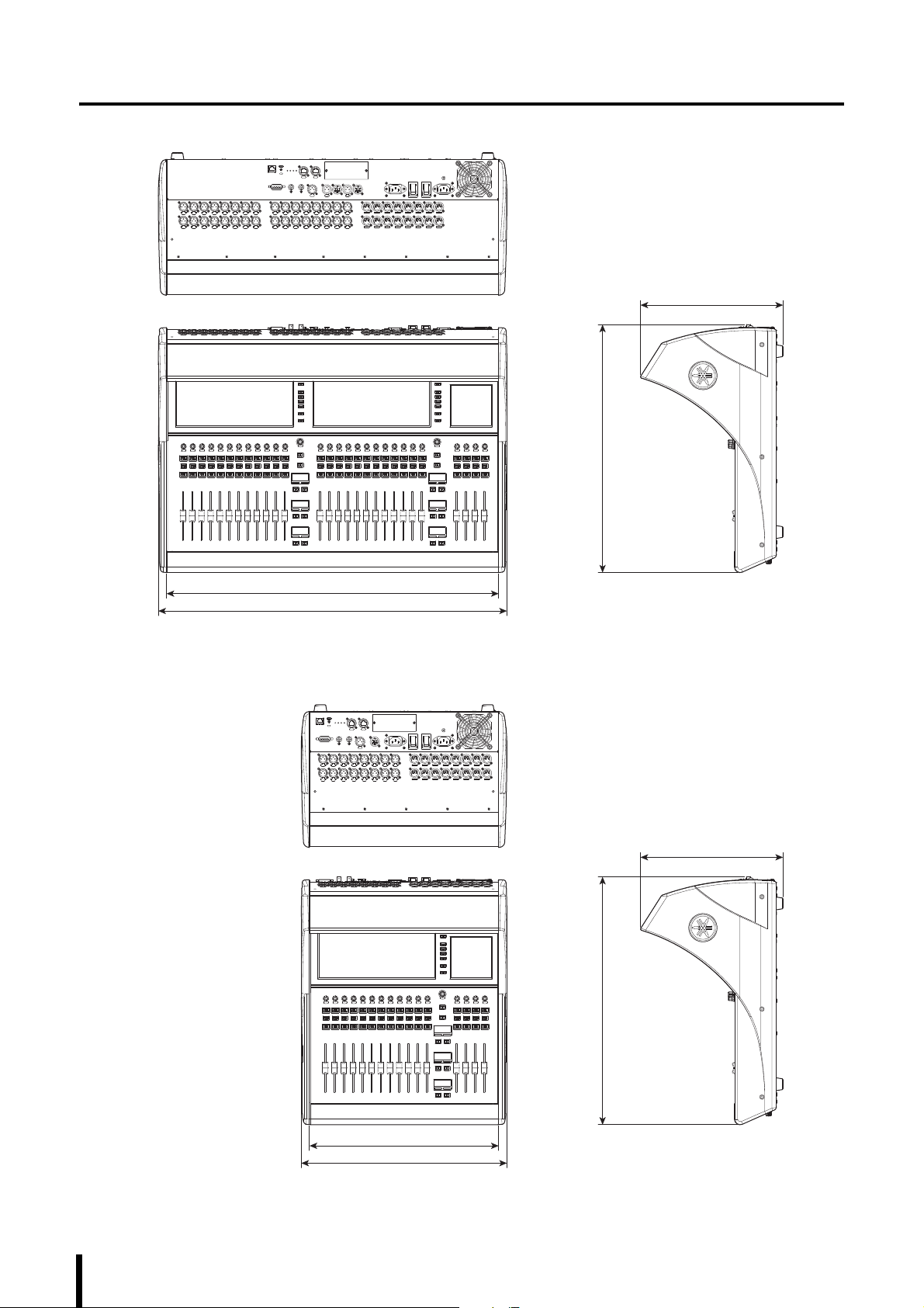
Dimensions
324
756
564
793
Unit: mmApproximate Munsell value of exterior color: N2.25
Unit: mmApproximate Munsell value of exterior color: N2.25
324
564
430
468
DM7
DM7 COMPACT
20
DM7 Console Owner’s Manual
Page 21

Source Code Distribution
For three years after the final factory shipment, you may request from Yamaha the source code for any portions of the product
which are licensed under the GNU General Public License / GNU Lesser General Public License / RealNetworks Public Source
License by writing to the following address:
10-1 Nakazawa-cho, Naka-ku, Hamamatsu, 430-8650, JAPAN
Marketing & Sales Department, Professional Audio Division, Audio Products Business Unit, Yamaha Corporation
The source code will be provided at no charge; however, we may require you to reimburse Yamaha for the cost of delivering
the source code to you. The source code can be downloaded by visiting the following URL:
https://www.yamahaproaudio.com/
• Note that we shall bear no responsibility whatsoever for any damage arising from changes (additions/deletions) made to the
software for this product by a third party other than Yamaha (or party authorized by Yamaha).
• Note that re-use of source code released to the public domain by Yamaha is not guaranteed. Yamaha shall not bear any
responsibility whatsoever for the source code.
DM7 Console Owner’s Manual
21
Page 22
ADDRESS LIST
NORTH AMERICA
CANADA
Yamaha Canada Music Ltd.
135 Milner Avenue, Toronto, Ontario,
M1S 3R1, Canada
Tel: +1-416-298-1311
U.S.A.
Yamaha Corporation of America
6600 Orangethorpe Avenue, Buena Park, CA
90620, U.S.A.
Tel: +1-714-522-9011
CENTRAL & SOUTH AMERICA
MEXICO
Yamaha de México, S.A. de C.V.
Av. Insurgentes Sur 1647 Piso 9, Col. San José
Insurgentes, Delegación Benito Juárez, CDMX,
C.P. 03900, México
Tel: +52-55-5804-0600
BRAZIL
Yamaha Musical do Brasil Ltda.
Praça Professor José Lannes, 40-Cjs 21 e 22,
Brooklin Paulista Novo CEP 04571-100 – São
Paulo – SP, Brazil
Tel: +55-11-3704-1377
ARGENTINA
Yamaha Music Latin America, S.A.,
Sucursal Argentina
Olga Cossettini 1553, Piso 4 Norte,
Madero Este-C1107CEK,
Buenos Aires, Argentina
Tel: +54-11-4119-7000
PANAMA AND OTHER LATIN
AMERICAN/CARIBBEAN REGIONS
Yamaha Music Latin America, S.A.
Edif. Torre Banco General, Piso 7, Urbanización
Marbella, Calle 47 y Aquilino de la Guardia,
Ciudad de Panamá, República de Panamá
Tel: +507-269-5311
EUROPE
THE UNITED KINGDOM/IRELAND
Yamaha Music Europe GmbH (UK)
Sherbourne Drive, Tilbrook, Milton Keynes,
MK7 8BL, U.K.
Tel: +44-1908-366700
GERMANY
Yamaha Music Europe GmbH
Siemensstrasse 22-34, 25462 Rellingen, Germany
Tel: +49-4101-303-0
SWITZERLAND/LIECHTENSTEIN
Yamaha Music Europe GmbH, Branch
Switzerland in Thalwil
Seestrasse 18a, 8800 Thalwil, Switzerland
Tel: +41-44-3878080
AUSTRIA/BULGARIA/
CZECH REPUBLIC/HUNGARY/
ROMANIA/SLOVAKIA/SLOVENIA
Yamaha Music Europe GmbH
Branch Austria
Schleiergasse 20, 1100 Wien, Austria
Tel: +43-1-60203900
POLAND
Yamaha Music Europe
Sp.z o.o. Oddział w Polsce
ul. Młynarska 48, 01-171 Warszawa, Poland
Tel: +48-22-880-08-88
MA LTA
Olimpus Music Ltd.
Valletta Road, Mosta MST9010, Malta
Tel: +356-2133-2093
NETHERLANDS/BELGIUM/LUXEMBOUR
G
Yamaha Music Europe Branch Benelux
Wattbaan 1 3439ML Nieuwegein, The Netherlands
Tel: +31-347-358040
FRANCE
Yamaha Music Europe
7 rue Ambroise Croizat, Zone d'activités de Pariest,
77183 Croissy-Beaubourg, France
Tel: +33-1-6461-4000
ITALY
Yamaha Music Europe GmbH, Branch Italy
Via Tinelli N.67/69 20855 Gerno di Lesmo (MB),
Italy
Tel: +39-039-9065-1
SPAIN/PORTUGAL
Yamaha Music Europe GmbH Ibérica, Sucursal
en España
Ctra. de la Coruña km. 17,200, 28231
Las Rozas de Madrid, Spain
Tel: +34-91-639-88-88
GREECE
Philippos Nakas S.A. The Music House
19th klm. Leof. Lavriou 190 02 Peania – Attiki,
Greece
Tel: +30-210-6686168
SWEDEN/FINLAND/ICELAND
Yamaha Music Europe GmbH Germany Filial
Scandinavia
JA Wettergrensgata 1, 400 43 Göteborg, Sweden
Tel: +46-31-89-34-00
DENMARK
Yamaha Music Denmark,
Fillial of Yamaha Music Europe GmbH, Tyskland
Generatorvej 8C, ST. TH. , 2860 Søborg, Denmark
Tel: +45-44-92-49-00
NORWAY
Yamaha Music Europe GmbH Germany Norwegian Branch
c/o Box 30053, 400 43 Göteborg, Sweden
Tel: +47-6716-7800
CYPRUS
Yamaha Music Europe GmbH
Siemensstrasse 22-34, 25462 Rellingen, Germany
Tel: +49-4101-303-0
RUSSIA
Yamaha Music (Russia) LLC.
Room 37, entrance 7, bld. 7, Kievskaya street,
Moscow, 121059, Russia
Tel: +7-495-626-5005
OTHER EUROPEAN REGIONS
Yamaha Music Europe GmbH
Siemensstrasse 22-34, 25462 Rellingen, Germany
Tel: +49-4101-3030
AFRICA
Yamaha Music Gulf FZE
JAFZA-16, Office 512, P.O.Box 17328,
Jebel Ali FZE, Dubai, UAE
Tel: +971-4-801-1500
MIDDLE EAST
TURKEY
Ertekin Electronik tlc. ve san. as
Kagithane Ofis ParkBaglar Cad.
No: 14 D/6 Kagithane 34406
ISTANBUL / TÜRKIYE
Tel: +90-212-312-24-24
OTHER REGIONS
Yamaha Music Gulf FZE
JAFZA-16, Office 512, P.O.Box 17328,
Jebel Ali FZE, Dubai, UAE
Tel: +971-4-801-1500
ASIA
MAINLAND CHINA
Yamaha Music & Electronics (China) Co.,Ltd.
2F, Yunhedasha, 1818 Xinzha-lu, Jingan-qu,
Shanghai, China
Tel: +86-400-051-7700
INDIA
Yamaha Music India Private Limited
P-401, JMD Megapolis, Sector-48, Sohna Road,
Gurugram-122018, Haryana, India
Tel: +91-124-485-3300
INDONESIA
PT Yamaha Musik Indonesia Distributor
Yamaha Music Center Bldg. Jalan Jend. Gatot
Subroto Kav. 4, Jakarta 12930, Indonesia
Tel: +62-21-520-2577
KOREA
Yamaha Music Korea Ltd.
11F, Prudential Tower, 298, Gangnam-daero,
Gangnam-gu, Seoul, 06253, Korea
Tel: +82-2-3467-3300
MALAYSIA
Yamaha Music (Malaysia) Sdn. Bhd.
No.8, Jalan Perbandaran, Kelana Jaya, 47301
Petaling Jaya, Selangor, Malaysia
Tel: +60-3-78030900
SINGAPORE
Yamaha Music (Asia) Private Limited
Block 202 Hougang Street 21, #02-00,
Singapore 530202, Singapore
Tel: +65-6740-9200
TAI WAN
Yamaha Music & Electronics Taiwan Co.,Ltd.
2F., No.1, Yuandong Rd., Banqiao Dist.,
New Taipei City 22063, Taiwan
Tel: +886-2-7741-8888
THAILAND
Siam Music Yamaha Co., Ltd.
3, 4, 15, 16th Fl., Siam Motors Building,
891/1 Rama 1 Road, Wangmai,
Pathumwan, Bangkok 10330, Thailand
Tel: +66-2215-2622
VIETNAM
Yamaha Music Vietnam Company Limited
15th Floor, Nam A Bank Tower, 201-203 Cach
Mang Thang Tam St., Ward 4, Dist.3,
Ho Chi Minh City, Vietnam
Tel: +84-8-3818-1122
OTHER ASIAN REGIONS
http://asia.yamaha.com/
OCEANIA
AUSTRALIA
Yamaha Music Australia Pty. Ltd.
Level 1, 80 Market Street, South Melbourne,
VIC 3205, Australia
Tel: +61-3-9693-5111
REGIONS AND TRUST TERRITORIES
IN PACIFIC OCEAN
http://asia.yamaha.com/
Head Office/Manufacturer: Yamaha Corporation 10-1, Nakazawa-cho, Naka-ku, Hamamatsu, 430-8650, Japan
Importer (European Union): Yamaha Music Europe GmbH Siemensstrasse 22-34, 25462 Rellingen, Germany
Importer (United Kingdom): Yamaha Music Europe GmbH (UK) Sherbourne Drive, Tilbrook, Milton Keynes, MK7 8BL, United Kingdom
22
DM7 Console Owner’s Manual
PA5 9
Page 23

MEMO
DM7 Console Owner’s Manual
23
Page 24

© 2023 Yamaha Corporation
Published 03/2023
IPEM-A0
VFJ1430
Yamaha Downloads
https://download.yamaha.com/
Yamaha Pro Audio global website
https://www.yamahaproaudio.com/
 Loading...