


 CDX-880/580/480
Natural Sound Compact Disc Player
Random Access Programmable Play
Random-Sequence Play
Single Track/Entire Disc Repeat Play
Automatic Spacing Capability
Automatic Tape-Programming
Automatic Peak Level Searching Capability
CD Synchronized Recording with a Compatible YAMAHA Tape Disk
Display Brightness Changing Capability
Remote Control Capability
Thank you for selecting this YAMAHA Compact Disc Player.
OWNER’S MANUAL |
|
CONTENTS |
|
Safety Instructions.................... |
2 |
Connections ............................. |
4 |
Identification of Components.... |
6 |
Loading the Disc/Disc Play....... |
8 |
Random-Sequence Play ........ |
12 |
Repeat Play............................ |
12 |
Program Play.......................... |
13 |
Index Search .......................... |
14 |
Track Programming for |
|
Recording to Tape .................. |
15 |
CD Synchronized Recording ...... |
19 |
Notes about the Remote |
|
Control Transmitter ................. |
20 |
Notes about Handling |
|
Compact Discs ....................... |
20 |
Troubleshooting ...................... |
21 |
Specifications ......................... |
21 |
IMPORTANT!
Please record the serial number of this
unit in the space below.
Model:
Serial No.:
The serial number is located on the rear
of the unit.
Retain this Owner’s Manual in a safe
place for future reference.
WARNING
TO REDUCE THE RISK OF FIRE OR
ELECTRIC SHOCK, DO NOT EXPOSE
THIS UNIT TO RAIN OR MOISTURE.
CAUTION
RISK OF ELECTRIC SHOCK
DO NOT OPEN
CAUTION: TO REDUCE THE RISK OF
ELECTRIC SHOCK, DO NOT REMOVE
COVER (OR BACK), NO USER-SERVICEABLE PARTS INSIDE, REFER SERVICING TO QUALIFIED SERVICE PERSONNEL.
• Explanation of Graphical Symbols
The lightning flash with arrowhead
symbol, within an equilateral triangle,
is intended to alert you to the presence of uninsulated “dangerous voltage” within the product’s enclosure that may be of sufficient
magnitude to constitute a risk of
electric shock to persons.
The exclamation point within an equilateral triangle is intended to alert
you to the presence of important operating and maintenance (servicing) instructions in the
literature accompanying the
appliance.
SAFETY INSTRUCTIONS
CAUTION
RISK OF ELECTRIC SHOCK
DO NOT OPEN
CAUTION: TO REDUCE THE RISK OF
ELECTRIC SHOCK, DO NOT REMOVE
COVER (OR BACK). NO USER-SERVICEABLE
PARTS INSIDE. REFER SERVICING TO
QUALIFIED SERVICE PERSONNEL.
• Explanation of Graphical Symbols
The lightning flash with arrowhead symbol, within an equilateral triangle, is intended to alert you to the presence of uninsulated “dangerous voltage” within the product’s enclosure that may be of sufficient magnitude to constitute a risk of electric shock to persons.
The exclamation point within an equilateral triangle is intended to alert you to the presence of important operating and maintenance (servicing) instructions in the literature accompanying the appliance.
WARNING
TO REDUCE THE RISK OF FIRE OR
ELECTRIC SHOCK, DO NOT EXPOSE THIS
UNIT TO RAIN OR MOISTURE.
1Read Instructions – All the safety and operating instructions should be read before the unit is operated.
2Retain Instructions – The safety and operating instructions should be retained for future reference.
3Heed Warnings – All warnings on the unit and in the operating instructions should be adhered to.
4Follow Instructions – All operating and other instructions should be followed.
5Water and Moisture – The unit should not be used near water – for example, near a bathtub, washbowl, kitchen sink, laundry tub, in a wet basement, or near a swimming pool, etc.
6Carts and Stands – The unit should be used only with a cart or stand that is recommended by the manufacturer.
6A A unit and cart combination should be moved with care. Quick stops, excessive force, and uneven surfaces may cause the unit and cart combination to overturn.
7Wall or Ceiling Mounting – The unit should be mounted to a wall or ceiling only as recommended by the manufacturer.
8Ventilation – The unit should be situated so that its location or position does not interfere with its proper ventilation. For example, the unit should not be situated on a bed, sofa, rug, or similar surface, that may block the ventilation openings; or placed in a built-in installation, such as a bookcase or cabinet that may impede the flow of air through the ventilation openings.
9Heat – The unit should be situated away from heat sources such as radiators, stoves, or other appliances that produce heat.
10Power Sources – The unit should be connected to a power supply only of the type described in the operating instructions or as marked on the unit.
11Power-Cord Protection – Power-supply cords should be routed so that they are not likely to be walked on or pinched by items placed upon or against them, paying particular attention to cords at plugs, convenience receptacles, and the point where they exit from the unit.
12Cleaning – The unit should be cleaned only as recommended by the manufacturer.
13Nonuse Periods – The power cord of the unit should be unplugged from the outlet when left unused for a long period of time.
14Object and Liquid Entry – Care should be taken so that objects do not fall into and liquids are not spilled into the inside of the unit.
15Damage Requiring Service – The unit should be serviced by qualified service personnel when:
A.The power-supply cord or the plug has been damaged; or
B.Objects have fallen, or liquid has been spilled into the unit; or
C.The unit has been exposed to rain; or
D.The unit does not appear to operate normally or exhibits a marked change in performance; or
E.The unit has been dropped, or the cabinet damaged.
16Servicing – The user should not attempt to service the unit beyond those means described in the operating instructions. All other servicing should be referred to qualified service personnel.
17Power Lines – An outdoor antenna should be located away from power lines.
18Grounding or Polarization – Precautions should be taken so that the grounding or polarization is not defeated.
We Want You Listening For A Lifetime
(for US customers only)
YAMAHA and the Electronic Industries Association’s Consumer Electronics Group want you to get the most out of your equipment by playing it at a safe level. One that lets the sound come through loud and clear without annoying blaring or distortion – and, most importantly, without
affecting your sensitive hearing. Since hearing damage from loud sounds is often undetectable until it is too late, YAMAHA and the Electronic Industries Association’s Consumer Electronics Group recommend you to avoid prolonged
IMPORTANT!
Please record the serial number of this unit in the space below.
Model:
Serial No.:
The serial number is located on the rear of the unit. Retain this Owner’s Manual in a safe place for future reference
2
CAUTION: READ THIS BEFORE OPERATING YOUR UNIT
1To ensure the finest performance, please read this manual carefully. Keep it in a safe place for future reference.
2Install your unit in a cool, dry, clean place – away from windows, heat sources, and too much vibration, dust, moisture or cold. Avoid sources of hum (transformers, motors). To prevent fire or electrical shock, do not expose to rain and water.
3Do not operate the unit upside-down. It may overheat, possibly causing damage.
4Never open the cabinet. If a foreign object drops into the set, contact your dealer.
5Do not use force on switches, knobs or cords. When moving the set, first turn the unit off. Then gently disconnect the power plug and the cords connecting to other equipment. Never pull the cord itself.
6Do not attempt to clean the unit with chemical solvents; this might damage the finish. Use a clean, dry cloth.
7Be sure to read the “TROUBLESHOOTING” section on common operating errors before concluding that your unit is faulty.
8.Do not place another component on top of this unit, because to do so will discolor or damage the surface of the unit.
9.To prevent damage by lightning, disconnect the power cord from the household AC outlet during an electrical storm.
10.When disconnecting the power cord from the household AC outlet, grasp the plug; do not pull the cord.
11.When moving the unit, be sure to first disconnect the power cord from the household AC outlet, and disconnect cords connected to other equipment.
The apparatus is not disconnected from the AC power source as long as it is connected to the wall outlet, even if the apparatus itself is turned off.
WARNING
CAUTION
Use of controls or adjustments or performance of procedures other than those specified herein may result in hazardous radiation exposure.
DANGER
Invisible laser radiation when open and interlock failed or defeated.
Avoid direct exposure to beam.
As the laser beam used in this compact disc player is harmful to the eyes, do not attempt to disassemble the cabinet. Refer servicing to qualified personel only.
To avoid electrical shock, do not open the unit. Refer servicing to qualified personnel only.
DANGER: The use of optical instrument with this product will increase eye hazard.
Laser Diode Properties
•Material: GaAlAs
•Wavelength: 780nm
•Emission Duration: continuous
•Laser Output: max. 44.6µW*
*This output is the value measured at a distance of about 200mm from the objective lens surface on the Optical Pickup Block.
FCC INFORMATION (for US customers only)
1. IMPORTANT NOTICE : DO NOT MODIFY THIS UNIT! |
Compliance with FCC regulations does not guarantee that |
|
This product, when installed as indicated in the |
interference will not occur in all installations. If this product |
|
instructions contained in this manual, meets FCC |
is found to be the source of interference, which can be |
|
requirements. Modifications not expressly approved by |
determined by turning the unit “OFF” and “ON”, please try |
|
Yamaha may void your authority, granted by the FCC, to |
to eliminate the problem by using one of the following |
|
use the product. |
measures: |
|
2. IMPORTANT : When connecting this product to |
Relocate either this product or the device that is being |
|
accessories and/or another product use only high quality |
affected by the interference. |
|
shielded cables. Cable/s supplied with this product |
Utilize power outlets that are on different branch (circuit |
|
MUST be used. Follow all installation instructions. |
||
breaker or fuse) circuits or install AC line filter/s. |
||
Failure to follow instructions could void your FCC |
||
In the case of radio or TV interference, relocate/reorient the |
||
authorization to use this product in the USA. |
||
3. NOTE : This product has been tested and found to |
antenna. If the antenna lead-in is 300 ohm ribbon lead, |
|
change the lead-in to coaxial type cable. |
||
comply with the requirements listed in FCC Regulations, |
||
If these corrective measures do not produce satisfactory |
||
Part 15 for Class “B” digital devices. Compliance with |
||
these requirements provides a reasonable level of |
results, please contact the local retailer authorized to |
|
assurance that your use of this product in a residential |
distribute this type of product. If you can not locate the |
|
environment will not result in harmful interference with |
appropriate retailer, please contact Yamaha Electronics |
|
other electronic devices. |
Corp., U.S.A. 6660 Orangethorpe Ave, Buena Park, CA |
|
This equipment generates/uses radio frequencies and, if |
90620. |
|
|
||
not installed and used according to the instructions |
The above statements apply ONLY to those products |
|
found in the users manual, may cause interference |
distributed by Yamaha Corporation of America or its |
|
harmful to the operation of other electronic devices. |
subsidiaries. |
3

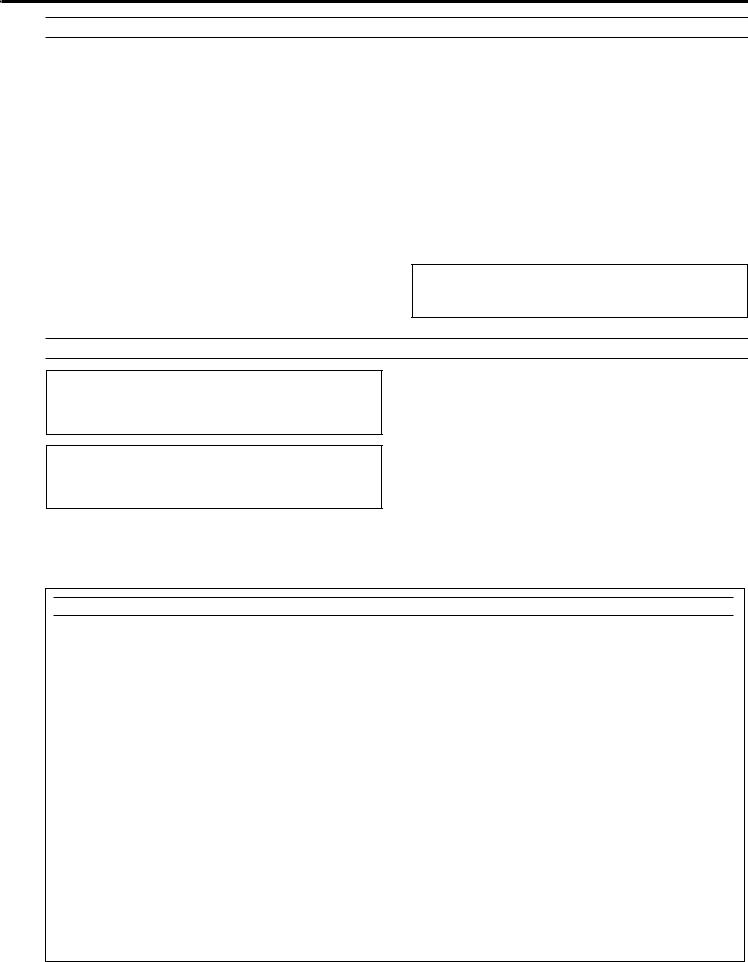
CONNECTIONS
•Before making any connections, switch OFF the power to the unit and the amplifier or other component.
•Connections should be made to the correct input terminals of the amplifier or other component.
•If the placement of this unit causes noise to other equipment, such as a tuner, separate them from each other.
CDX-880
LINE OUT |
|
DIGITAL OUT |
|
||
|
|
|
VARIABLE FIXED
OPTICAL COAXIAL
CDX-880
To AC outlet
|
|
|
|
|
|
||
Optical fiber cable |
Connection cord |
||
(not included) |
|||
(not included) |
|
||
|
|
||
|
|
|
|
Connection cord |
|
Amplifier |
|
(included) |
|
||
|
OPTICAL COAXIAL |
||
CD |
DIGITAL IN |
||
CDX-580
|
LINE OUT |
|
|
|
DIGITAL OUT |
|
||
|
|
|
|
|||||
|
|
|
|
|
|
|
|
|
|
|
|
|
|
|
|
|
|
|
|
|
|
|
|
|
|
|
|
|
|
|
|
|
|
|
|
|
|
|
|
|
|
|
|
|
CDX-580
To AC outlet
Connection cord (not included)
Connection cord
(included)
Amplifier
COAXIAL
CD |
DIGITAL IN |
4
CDX-480
|
|
|
LINE OUT |
|
|
|
|
|
|
|
|
|
|
|
CDX-480 |
||||||||
|
|
|
|
|
|
|
|
|
|
|
|
|
|||||||||||
|
|
|
|
|
|
|
|
|
|
|
|
|
|
|
|
|
|
|
|
|
|
|
|
|
|
|
|
|
|
|
|
|
|
|
|
|
|
|
|
|
|
|
|
|
|
|
|
|
|
|
|
|
|
|
|
|
|
|
|
|
|
|
|
|
|
|
|
|
|
|
|
|
|
|
|
|
|
|
|
|
|
|
|
|
|
|
|
|
|
|
|
|
|
|
|
|
|
|
|
|
|
|
|
|
|
|
|
|
|
|
|
|
|
|
|
|
|
|
|
|
|
|
|
|
|
|
|
|
|
|
|
|
|
|
|
|
|
|
|
|
|
|
|
|
|
|
|
|
|
|
|
|
|
|
|
|
|
|
|
|
|
|
|
|
|
|
|
 To AC outlet
Connection cord |
Amplifier |
|
(included) |
||
|
CD
Choose one of the ways listed below to connect this unit to your amplifier.
When the LINE OUT (analog) terminals of this unit are used ( )
•Be sure that the left (“L”) and right (“R”) LINE OUT terminals are connected to the corresponding (left and right) terminals of the amplifier or other component.
•Connect the “LINE OUT” terminals to the “CD” (or “AUX”) terminals of the amplifier. If the amplifier does not have such terminals, use the “TAPE PB” terminals. For additional details concerning these connections, refer to the operation instructions for the amplifier being used.
•CDX-880 only
Connect to either the VARIABLE terminals or the FIXED terminals. (As a general rule, connect to the FIXED terminals.)
VARIABLE:
CDX-880 only
When the DIGITAL OUT (OPTICAL) terminal of this unit is used ( )
•Before using this terminal, remove the terminal’s cover by pulling it.
•Make the connection from this terminal to the optical input terminal of an amplifier by using a commercially available optical fiber cable.
*Use an optical fiber cable that conforms to EIAJ standards. Other cables might not function correctly.
•Be sure to attach the terminal’s cover when this terminal is not being used, in order to protect the terminal from dust.
•The level of signals output into an amplifier is fixed to max. and cannot be adjusted.
|
|
CDX-880 and CDX-580 only |
|
||
FIXED: |
When the DIGITAL OUT (COAXIAL) terminal of |
||||
|
this unit is used ( ) |
||||
|
• |
|
Make the connection from this terminal to the digital input |
||
|
|
|
terminal of an amplifier or D/A (digital-to-analog) converter |
||
|
• |
|
by using a connection cord. |
||
|
|
CDX-880 only |
|
|
|
|
|
|
The level of signals output into an amplifier is fixed to max. |
||
|
• |
|
and cannot be adjusted. |
||
|
|
CDX-580 only |
|
|
|
Adjust the level of signals output into an amplifier to max. by using the OUTPUT LEVEL buttons.
5
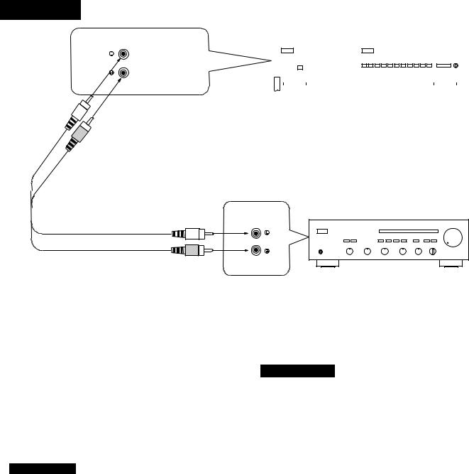
IDENTIFICATION OF COMPONENTS
* ( ) indicates the page number on which the control part is best described.
FRONT PANEL
*The control functions on the main unit and on the remote control transmitter are virtually identical, with the exceptions below.
*The PLAY/PAUSE button on the main unit has both the functions of the PLAY button and the PAUSE button on the remote control transmitter.
CDX-880
POWER switch (p. 8)
AUTO DISPLAY OFF indicator (p. 11)
OUTPUT LEVEL control (p. 11)
POWER switch (p. 8)
POWER |
OPEN/CLOSE |
|
|
|
|
|
|
|
|
|
STOP |
PLAY/PAUSE |
|
|
PROG |
TAPE |
PEAK |
SPACE |
INDEX |
REPEAT RANDOM |
|
SKIP |
|
SEARCH |
|
|
|
|
AUTO |
|
|
|
|
|
|
|
|
|
|
PHONES |
OUTPUT LEVEL |
|
DISPLAY OFF |
|
|
|
|
|
|
|
|
|
|
||
|
|
|
|
|
|
|
|
|
|
|
|
|
|
|
+10 |
1 |
2 |
3 |
4 |
5 |
6 |
7 |
8 |
9 |
0 |
TIME |
|
Display panel
PHONES jack (p. 11)
Remote control sensor (p. 20)
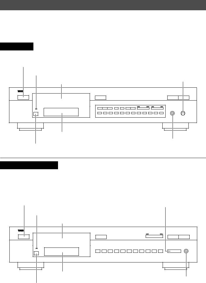
CDX-580, CDX-480
*The SKIP/SEARCH button on the main unit has both the functions of the SKIP buttons and the SEARCH buttons on the remote control transmitter.
POWER switch (p. 8) |
OUTPUT LEVEL control (p. 11) |
||
AUTO DISPLAY OFF indicator (p. 11) |
|
(p. 11) |
|
CDX-580 only |
|
||
POWER switch (p. 8) |
|
|
|
POWER |
|
OPEN/CLOSE |
|
|
|
|
|
|
|
SKIP/SEARCH |
|
STOP |
|
PLAY/PAUSE |
|
|
AUTO |
+10 |
1 |
2 |
3 |
4 |
5 |
6 |
7 |
8 |
9 |
0 |
OUTPUT LEVEL |
PHONES |
|
|
DOWN |
UP |
|||||||||||||
|
DISPLAY OFF |
||||||||||||||
Display panel
PHONES jack (p. 11)
Remote control sensor (p. 20)
6
* ( ) indicates the page number on which the control part is best described.
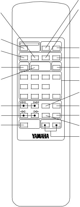
REMOTE CONTROL TRANSMITTER
TAPE button (p. 15)
OPEN/CLOSE button (p. 8)
OPEN/CLOSE DIMMER TIME
PROG button (p. 13)
|
PROG |
TAPE |
CLEAR |
PEAK |
|
SPACE |
S/F |
|
RANDOM |
SPACE button (p. 10) |
|
|
REPEAT |
|
|
1 |
2 |
3 |
+10 |
REPEAT button (p. 10) |
4 |
5 |
6 |
|
|
|
|||
|
7 |
8 |
9 |
0 |
SKIP buttons (p. 9) |
SKIP |
PAUSE |
PLAY |
|
|
|
|
|
|
|
SEARCH |
INDEX |
STOP |
|
SEARCH buttons (p. 10) |
|
|
|
|
|
|
|
– OUTPUT LEVEL + |
|
SYNCHRO button (p. 19) |
|
SYNCHRO |
|
|
DIMMER button (p. 11)
CLEAR button (p. 14)
TIME button (p. 10)
PEAK button (p. 18)
RANDOM button (p. 12)
Numeric buttons (p. 9)
PAUSE button (p. 9)
PLAY button (p. 8)
STOP button (p. 9)
INDEX button (p. 14)
OUTPUT LEVEL buttons (p. 11)
7
 Loading...