

Yamaha 1978 SS338, 1976 SS433, 1977 SS433, 1977 SS338, 1978 SS433 Condensed Service Data
...
Yamaha
ENGINES
YAMAHA
1976
AND
LATER
E338, SS338 AN D SS433 TWO
CYLINDER MODELS
CONDENSED SERVICE DATA
Engine
Model
E338
88338 88433
Bore-(mm). .
..
. .
...
. . . ... . .
....
60
60 68
Inches
......... .............
2.362
2.362 2.677
Str
oke-(mm)
.... . ..
...
..
. .
...
. .
59.6
59.6
59.6
Inches
..
........
... .
....
....
2.346
2.340 2.346
No. of Cylinders
..
. .
...
.... . ....
2
2
2
Displacement-co . . ... . . . . ... . . . .
338 338 433
Cubic Inches
.........
...
.... .
20
I).
20.63 26.4
CoolingType .
..........
........
Free Air" Free Air Free Air"
Carburetor Model
....
. .
.. . ..
.
Mikuni (B) Keihin (PW) Keihin
(PW)"
Number Used
.... ..... , ...... 1 1 1
Ignition:
Type
.. ... ..
, .... ....
cm cm cm
Timing BT,_('
..............
1.5-1.7 mm
1.6mm 1.6mm
Spark P'
,
Li
........................
BR9EV""
BR9EV
BR9EV""
·1·
Electrode Gap(mm) .
.......
. 0.5-0.6t 0.5-0.6 0.5-0.6
Inch . . . . .
....
. . .
..
.. . ..
.
0.020-0.024t 0.020-0.024
0.020-0.024
Fuel/OilRatio
....
...
.....
. .
..
. . Autolube Autolube Autolube
"Models prior to 1980 use Free Air cooling. All 198
0-1981
models are equipped with
Axial Fan .
""Engine models prior to 1978 use Keihin (PW) model carburetors. All 1978-1981
models use Keihin (BD) model carburetors.
"""Models prior to 1980 use BR9EV. All 1980-1981 models use BR9ES.
tModels prior to 1979 use 0.5-0.6 mm (0.020-0.024 inch) electrode gap. All
1979-1981 models use 0.7-0.8 mm (0.028-0.031 inch) electrode gap.
on E338 models, 2,000 rpm on S8338
Model
Number
MAINTENANCE
models and 1,500 rpm on 88433 models.
Initial fuel/air mixture setting is as
1976
8PARK
PLUG. Selection of spark
follows:
SS338
155
plug will depend upon type of service
SS433
155
and ambient temperature . Standard
Model
Turns Out
plug is given in Condensed Service Data
1977
table. Excessively cold weather and/or
1976-1977
8S338
150
light load conditions may require spark
88338
1
8S433
150
plugs of warmer heat range. Hard
88433
P/4
usage, heavy loads and warm weather
1978
may require spark plugs of colder heat
1978
S8338 140
range.
SS338
P/8
8S433 152
8S433
P/
2
E338
220
CARBURETOR. A Keihin (PW) type
carburetor is used on S8 models prior to
1979-1981
1979-1981
1978 and a Keihin (BD) type carburetor
88433
1
6
/8
8S433
145
is used on 1978-1981 SS models. A
E338
240
Mikuni (B) type carburetor is used on
1978-1981
E338 models. Carburetor is installed on
E338 1
If
carburetor is removed for
overhaul
,
a "Y" type intake manifold and provides
refer to LUBRICATION section for
syn
-
the fuel/air mixture to both cylinders.
Standard carburetor main
jet
is as
chronizing Autolube pump to throttle
Standard idle speed setting is 1,700 rpm
follows:
opening.
294
I
Yamaha
ENGINES
'
YAMAHA
1975
AND
EARLIER
338,396
AND
433cc
TWO CYLINDER MODELS
CONDENSED
SERVICE DATA
338, 396,
433
Engine
Model
810
811,81
3 818
8ore-{mm
) .
60 65 68
Inches .
2.36 2.56 2.68
Stroke
-{mm
) .
59.6
59.6 59.6
Inches .
2.35 2.35
2.35
No.ofCylinders .
2
2 2
Displacem
ent-{
cc) .
338
396
433
CubicInches .
20.6 24.1 26.4
Horsepower
@ RPM:
SL,SW,EW ..
24@5500 28@5500 30@5500
SS
,GP
..
32
@650
0 36@6000 40@6500
CoolingType . Cent. Fan Cent. Fan Cent. Fan
Carburetor Model . Keihin Keihin or Mikuni
Diaphragm Diaphragm
Number Used .
lor
2
lor
2 • v. 2
Ignition:
Type .
Energy
Transter
agneto
Point Gap .
See1'ex
t.
ext SeeText
Timing Advance? .
No No
No
Timing 8TDC .
Sf-
~
.\
t
See
Text
SeeText
,,
't
Spark Plug:'
SL,SW,EW . .
NGK NGK NGK
87HZ 87HZ 87HZ
\ .
SS,GP
NGK NGK Champion
, .
89H 87HZ N2G
F, . I rude Gap (mm) . .
0.5-0.6 0.5-0.6 0.5-0.6
'nch .
0.020-0.024 0.020-0.024 0.020-0.024
.. ,lV"Oil Ratio . 20 :1* 20:1*
Autolube
*
If,
not equipped with "Autolube".
MAINTENANCE
Data
for
recommended
plug
for
normal
SPARK
PLUGS.
Selection of
spark
use. Excessively cold
weather
and/or
plugs
will
depend
upon
type
of service,
light
load conditions
may
require
spark
ambient
temperature
and
horsepower
plugs
of
warmer
heat
range.
Hard
of
engine.
Refer to '
Conden
sed
Service
us
age,
heavy
loads,
warm
weather
and
higher
horsepower
may
require
spark
plugs
of colder he
at
range
:
CARBURETORS.
Various
carbure-
tors
have
been
used. Refer to
the
appro-
pri
ate
carburetor
paragr
aphs
in
FUN-
DAMENTALS
section
for
carburetor
service.
For
adju
stment
of
carburetors
and
"Autolube"
refer
to
the
appropriate
following
paragraphs
.
ONE
(KEIHIN
OR
MIKUNI
DIA-
PHRAGM
) CARBURETOR.
The
car-
buretor
is
installed
on a "Y"
type
inlet
manifold
and
provides
the
fuel-air
mix
-
ture
to
both
cylinders. Initial
fuel-air
mixture
setting
is as follows:
SL338 (Keihin)-
Idle
mixture
needle . . . 1
Va
turns
out
High
speed
mixture
needle
.. ..
. 1V4
turns
out
Fuel
level (F- Fig. 1A) .
..
..
39 mm
Inlet
lever
height
(H-Fig
. 1A) 5.7 mm
C. Cle
arance
N.
Nul
a
M.
Mark
T. Throttle shan
288
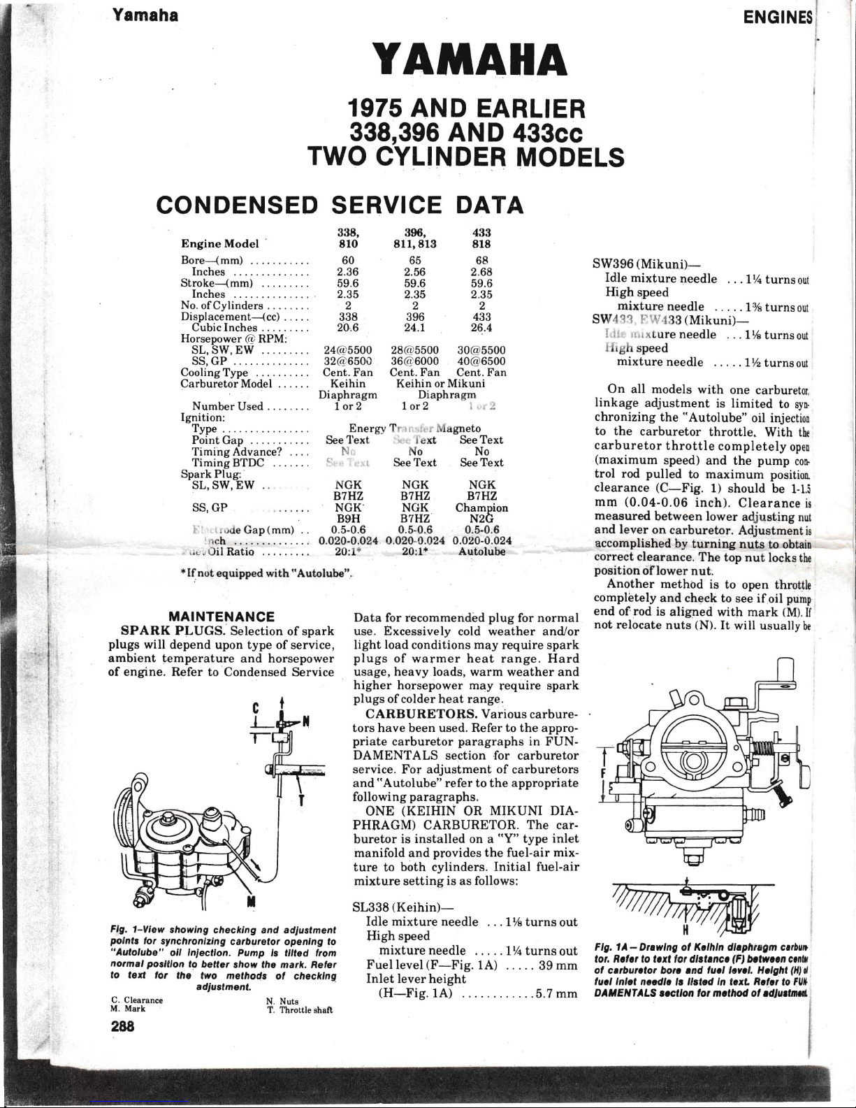
Fig. 1-Vlew showing checking and adJuslmenl
polnls fOI synchlon /z;ng carburelor opening 10
" Aulolube"
011
InJecl/on. Pump Is I//Ied from
nOlmal position
to better show the mark . Refer
to text for
ltie
Iwo
melhods
of checkIng
adJuslment. .
SW396 (Mikuni l-c-
Idle
mixture
needle ... 114
turns out
High
speed
mixture
needle
. . . . . 1%
turns out
SW433, RW 433 (Mikuni)-
Idt uu xture
needle
. . . 1Vaturnsou
t
I igh speed
mixture
needle . ..
. . 1
V2
turns out
On all models
with
one carburetor.
linkage
adjustment
is
limited
to
syn-
chronizing
the
"Autolube
" oil injection
to
the
carburetor
throttle.
With
t~
carburetor
throttle
completely
ope
n
(maximum
speed)
and
the
pump
con-
trol rod
pulled
to
maximum
position.
clearance
(C- Fig. 1) should be
1-1.5
mrn (0
.04-0
.06
inch).
Clearance
is
measured
between
lower adj
usting
nut
and
lever
on
carburetor.
Adjustment is
accomplished by
turning
nuts
to obta
in
correct
clearance.The
top
nut
locks
the
position
onower
nut.
Another
method
is to open throttle
completely
and
check to see
ifoil
pump
end
of rod is
aligned
with
mark (M).
If
not
relocate
nuts
(N).
It
will usually
be
~
'f
fl
// 111
0"
~
Fig. 1A - Dlew/ng
of
Kelhln d/ephlllgm c"butt
tOI.
Refel to text fOI distance (F) between c.nl.
of
clllbuletol
bOil
and fuel
Ilne/
. Height
(HI
01
fuel Inlet needle Is
listed
In text. Refe' to
FU,.
DAMENTALS section fOI method of
adJustmtllt

ERTER
st be
remembered
that
the
lit is
centrifug
ally
controlled
Iriven
unit
responds, therefore
.ion
and
belt
face
width
have
a
.aring on
alignment
of
sheave
re. Two
sheaves
which
are
in
alig n men t
with
correct
belt
will move
out
of
alignment
if
omes too
tight
or too loose.
Belt
ar or a
belt
of
incorrect
width
) change
alignment
and
tension
ough
shaft
center
distance
and
re as specified.
lost models,
the
drive
belt
can
be
ed
with a minimum
of
disas-
by
pulling
the
belt
into
bottom
ve of
driven
pulley
then
slipping
ff
drive
pulley.
Installation
is
~
of
rein
oval
procedure.
-n b
elt
is
removed
and/or
unit
is
' ~mb led
,
inspect
all
components
SPEED
TUNING
GENERAL
, torque
converter
unit
is involved
.Y
speed
tuning
decision for two
ns; re
sults
and
safety.
ere is
little point
in
spending
time
noney modifying
and
fine-tuning
ngine
unless the
drive
trai
n is
)!e of ma king the best us e of i,h e
'power
gained.
The
degree
of mod-
lion
of
the
converter
drive
and
.n
units
is so
inter-related
that
an
.t
procedure
cannot
be
outlined.
, section ,
therefore
, will
attempt
to
mly
the
principles
which
apply
and
precautions to be observed.
he
high
engine
speeds
associated
h
performance
tuning
makes
it
-era tive
that
care
be used in
main-
ling the
balance
and
trueness
of
lch
components. Racing
drive
ches
should
be
equipped
with
a
tter
sh
ield.
;peed
tuning
the
converter
unit
gen-
l
ly involves
raising
the
eng
agement
-ed, extra
attention
to
dynamic
bal-
ce of
the
total
unit,
careful
belt
selec-
n,
and
combating
down-shift
lag
of
iv en
member. The
final
step
in con-
rt
er
tuning
is
mating
the
drive
unit,
It and
driven
unit
into a carefully
.lanced
package
which will
transmit
Igine
power
to
the
track
in
its
most
fect ive form .
Although
the
principles
of
perform-
nee t uning
can
be
documented,
so
'an y
variables
are
involved
that
the
d ual
practice
depends
on
experimen-
ation,
experience
and
a feeling for
the
ib (coupled
with a fair
amount
ofluck)
h
at
only
the
outlines
of procedure
can
ie given .
DRIVE CLUTCH
Speed
tuning
an
engine
usually
sac-
carefully
for
wear
or
other
damage. If
wear
is
abnormal,
attempt
to discover
the
cause
before
completing
the
repairs
and
returning
the
vehicle to service.
Excessive or
uneven
wear
on sides of
vee
belt
may
indicate
pulley
misalign-
ment,
bent
pulley
half
or
improperly
adjusted
idle
speed. Examine
pulley
faces for
wear
patterns
or
heat
discolor-
ation.
Determine
and
correct
the
cause
of
trouble
rather
than
just
renew
the
belt. Sheave
parts
should
fit
with
a
minimum
of
clearance
without
binding
. Apply a
light
coating
of oil or
low
temperature
grease
to
sliding
parts,
but
make
sure
that
no excess
lubricant
will be
thrown
on
belt
or
sheave faces
when
unit
is
in
operation.
Check
for specific
overhaul
informa-
tion
and
disassembly
notes
in
the
unit
sections or
illustration
s.
rifices
torque
at
the
low
end
to
obtain
a
power
peak
in
the
performance
range.
The
degree
of
"peakiness"
depends
on
the
type
of
competition
involved
and
determines
the
tuning
of
the
drive
clutch
.
In a
family
machine,
the
drive
clutch
should engage
smoothly
at
a r
elatively
low
engine speed
and upshi
ft
smoothly
through
the
power
range
under
all
combinations
of
throttle
setting
and
load. The
converter
package
should
automatically
shift
down as
necessary
to
keep
from
lugging
the
engine.
With a "peaky"
competition engine,
engagement
speed
must
be
raised
above
the
stall-out
point
of
engine
tuning
and
total
balance
of
machine,
track
surface
and
converter
should
permit
almost
instantaneous
accelera-
tion
to
peak
horsepower
range.
As
previously
stated,
clutch
engage-
ment
speed
can
be
raised
by
lightening
the centrifugal
weights
or by
strength-
ening
the
reaction
spring.
Clutch
and
machine
manufacturers;
and
some
per
-
Fig. 8-Cross
sectional
view
of
governor
centrifugal
weights
showing:
M-Face
movement
and;
Dotted
IInes-welght
movement;
to
high
speed
'pos/llon. Kidney
type
weight
Is
shown
at
right
while
left-hand
view
\\
shows
curved
cam-arm
type
In
which
pivot
(P)
moves
and
fulcrum
(F) Is
fixed.
Removing
material
In
shaded
area
(E)
will
have
greater
effect
on
engage
-
ment
speed;
at
shaded
area
(X)
will
have
greater
effect
on
shift
pattern.
C.
Gravit
y cente rline
F.
Fulcrum point
M. Advan ce movem
ent
P. Cen
trif
ugal pivot
Speed
Tuning
formance
specialists,
make
heavier
springs
available. But
sometimes
the
'
spring
is
not
the
whole
answer.
Centri-
fugal force
increases
geometrically
as
speed
increases
and any
inherent
im-
balance
is
correspondingly
multiplied.
Also ,
heavy
centrifugal
weights
plus
high
speed
plus a correspondingly
strong
balance
spring
in
driven
unit
exert
heavy
side
pressure
on
drive
belt,
resulting
in
increased
belt
wear
and
frictional
loss of
power. For
these
rea-
sons,
weight
modification (or selection)
is also a widely
used
modification
tech
-
nique
.
A
new
compensating
spring
for a
competition
clutch
should
be
com-
pressed
in a vise
overnight
to
pre-set
the
spring
before
installation. Weights,
weight
pins, rollers
and
similar
parts
should
be
installed
only in
sets
and
carefully
weighed
and
balanced
(using
druggists
scales
or
equivalent)
before
installation
. :r
weights
are
altered
by
trimming,
balance
must
be
maintained
both
as to
total
weight
and
configura-
tion. Dynamic
balance
and
centrifugal
action
are
both
affected by
selection
of
trim
point. Refer
to
Fig
. 8. As a
general
rule,
removing
weight
farthe
st
from
pivot
point
(P ),
from
hea
.v.y
side
of
gravity
centerline
(C),
or
nearest
pulley
outer
rim
will
have
the
greater
centrif
ugal
effect.
And
material
nearer
pulley rim
will "weigh
mor
e", "'.'n a
dynamic
balance' standpoiu t th a n
equal
weight
nearer
the
hub.
Re-
moving weight
at
shaded
area
(E) will
affect
engagement
rpm
to a
greater
degree
while
removal
from
shaded
area
(X) will
have
greater
effect on
shift
pattern
. Do
not
remove
material
from
fulcrum
point
(F)
of
kidney
weight
(right)
or from
roller
contact
area
of
hammer
weight
(left)
when
lightening
the
weights.
Paint, rust,
gum
or
grease
must
be
removed
from
belt
contact
surfaces
of
pulley
faces
and
the
surfaces
kept
clean. Bushing
surfaces,
pivot
pins,
rollers
and
other
friction
points
must
c
315
 Loading...