

Page 1
Doc. No. OSA 072U-02
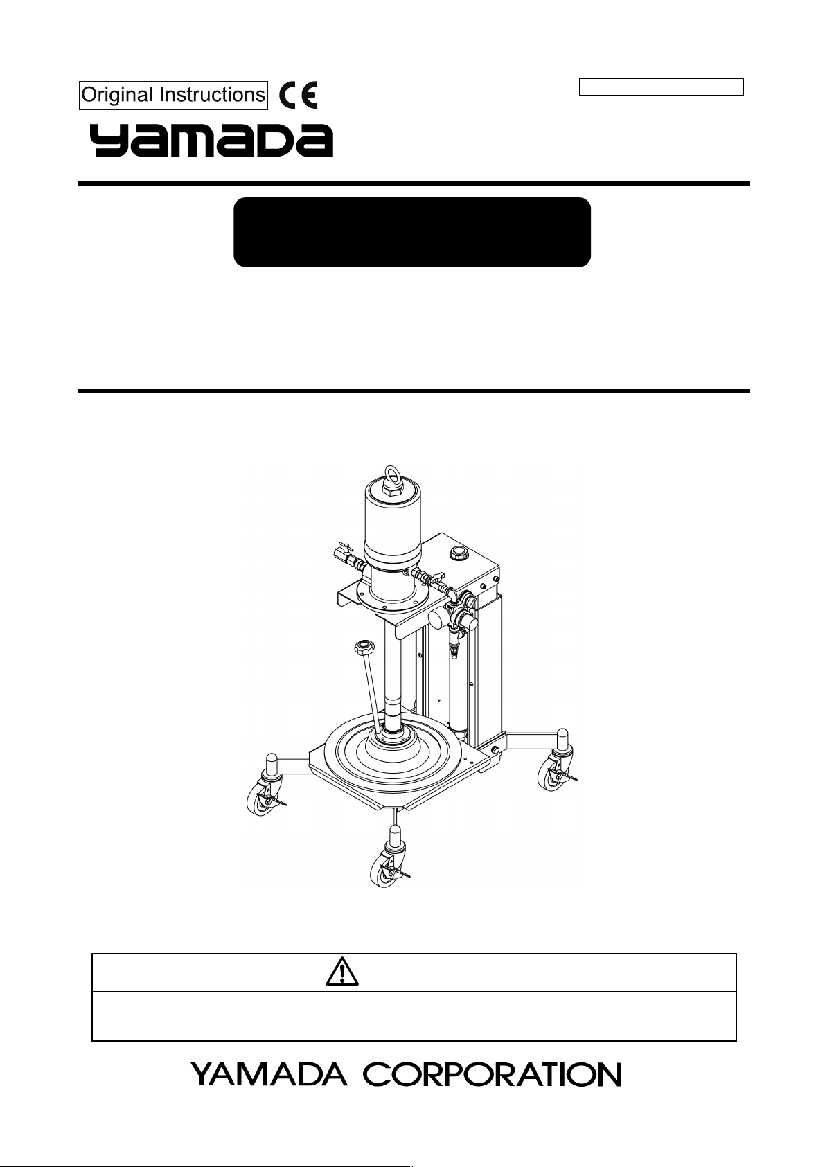
INSTRUCTION
GREASE LUBRICATOR
SKR110A50PAL MODEL No.881122
SKR110A50PAL-SL MODEL No.881123
WARNING
Prior to operating this pump, be sure to read this operation manual for safety. After reading the manual, please keep it at hand
any time for your quick reference.
Page 2
Page 3
- Preface
This machine is a Type 110 air-powered pump mounted on a trolley equipped with an airlift, and pressure-feeds
grease. It is best suited to fill products in the production line with grease as well as grease up vehicle and construction
equipment and maintain various devices and facilities in all areas.
Materials other than grease (such as putty and adhesive) cannot be used with this machine.
- For Safe Operation
This document describes the items that are important for the user to operate this product safety, correctly, and
efficiently. Before operating this product, read this manual thoroughly, in particular, “Warnings and Cautions” at the
beginning of this manual, with a good understanding of its contents. Keep this manual carefully in an easy-to-access
place so that the user may refer to it whenever necessary.
- Warnings and Cautions
To use this product safely, be sure to observe the contents of the following description. In this manual, warnings and
cautions are indicated by using symbols. These symbols are intended to prevent death or serious injury that may be
caused to the operator or those who are around the product and damage that may be caused to the articles that are
around the product, as well as to use the product safely and correctly. Each symbol is indicated and has a meaning as
shown below. Read the description with a good understanding of its contents.
WARNING :
This indicates the existence of potential hazard which, if not avoided, will
result in death or serious injury.
1 / 3
CAUTION :
To indicate the contents of danger and damage, the following symbols are used together with the above indications.
This symbol indicates an act that is prohibited (prohibition). The concrete contents of prohibition are
indicated by the side of the indication.
This symbol indicates the contents that must be observed. The concrete contents of observance are
indicated by the side of the indication.
This indicates the existence of potential hazard which, if not avoided, may
result in bodily injury or in physical damage.
Page 4
- Precautions on Use
The following warnings and cautions are very important. Be sure to observe them.
- Keep your face away from the exhaust and discharge ports. Material may suddenly come out. There is
a possibility of losing eyesight if it strikes eyes.
- Keep your face and hands away from the outlet when handling the check valve. Air-containing material
may suddenly come out. There is a possibility of losing eyesight and injuring the hand.
- Do not aim exhalation part of this product at any person. Residual pressure may be left inside the gun
even when the pump is not in operation. There is a possibility of losing eyesight if it strikes eyes.
- Gasoline is a high volatile fuel. Do not use it to clean the pump in any case, otherwise ignition or
explosion may be caused.
- Modification of this pump may lead to death, bodily injury, or a failure. Do not modify it in any case
because it involves a risk.
- Do not ride this product. There is a risk of falling.
- The operator and maintenance engineer should read the operation manual thoroughly before operating
this product and performing maintenance in respect of this product.
2 / 3
WARNING
- Always wear proper safety equipments (facemask, ear plugs, and safety shoes, etc.) when installing,
operating, and disassembling this product.
- Make sure the casters are locked during and after work to prevent unexpected movement of this
product. Also, do not use or leave this product in a slope or any unstable locations. The product, if not
locked, may move unpredictably, causing property damage or facility pollution. The user has a
responsibility for such secondary accidents.
- Make ground connection when working with flammable material or in explosive atmosphere. Rapid
pumping of material can result in static electrical charge. Also, be sure to provide proper ventilation
where a flammable atmosphere may exist.
- Execute the daily checkup.
- Use this product according to the product specification.
- Attach a valve (for stop in emergency) or regulator to the air supply pipe to keep supply air pressure
under 0.7MPa.
- If there is any danger or abnormality, discontinue pump operation and refer to Troubleshooting to solve
the problem.
- Stop pump operation immediately when a drum becomes empty. Running the pump dry will cause
excessive vibration, resulting in reduction of pump life and damage to other equipment.
- Before maintenance involving disassembly, be sure to shut off air supply to the pump and release
residual air pressure and material pressure in the tubes and pump. Failure to do so may result in
material gushing out.
- Do not discharge material directly onto the ground. Dispose of harmful materials according to the
requirements specified in MSDS or local regulations. Also, dispose of this product according to the local
regulations after removing residual material from inside this product. (Please contact industrial waste
disposal service.)
Page 5
3 / 3
CAUTION
- Keep hands and fingers away from this product during operation to avoid injury from moving parts.
- Use this product for the material suitable for the specification. Parts may be corroded and material leak
from the damaged parts can lead to environmental pollution. Also, follow handling notes (MSDS) of the
manufacturer about the handling of the material used.
- Take protective measures against rainwater and dust. It is likely to lead to the pollution of the material.
- Watch your step around this product to avoid tripping over the base and casters.
- Be careful about your hands when installing a pail. The edges of the cabinet and pail may cause hand
injury. Also, be careful about your posture when moving the pump to avoid back injury.
- Do not touch the surfaces of the pump and the hose when pumping high-temperature material. Risk of
burns exists.
- Shut off air source after work and nighttime, holidays, or when the pump is not in use for a while. Also,
open the valve at the discharge port to release residual pressure in the pump and hoses. Failure to do
so may result in damage to the hoses or facility pollution due to leak from the valve. The use has a
responsibility for such secondary accidents.
Page 6

Table of Contents
- Preface
- For Safe Operation
- Warnings and Cautions
- Precautions on Use
- Table of Contents
1. Part Names
1.1 Part Names ··················································································································· 1
1.2 Contents of Package ······································································································ 1
2. Preparations before Use
2.1 Assembling the machine ································································································· 2
2.2 Setting a grease pail
2.3 Bleeding air from grease
3. How to Use ························································································································· 5
3.1 Operation for using a high-pressure grease gun ································································ 6
3.2 Replacing a grease pail
4. Maintenance and Inspection
4.1 Troubleshooting and Corrective measures ······································································· 7
4.2 Maintenance and Inspection
4.3 Disassembly and Assembly ···························································································· 8
5. Exploded View and Parts List ····················································································· 10
6. Pump Specifications ···································································································
7. Trouble Information Fax Form ····················································································
8. Limited Warranty ················································································································ 13
······································································································ 2
································································································· 4
·································································································· 6
··························································································· 8
11
12
Page 7

1. Part Names
1.1 Part Names
1.2 Contents of Package
The main devices and the accessories are packed in different cases.
Open the top part of the corrugated fiberboard case and check if the devices is not damaged and if accessories are
all contained in the package.
1
Page 8

2. Preparations before Use
2.1 Assembling the machine
1) Casters are packed separately. Insert them into the caster base and
secure with the supplied bolts, plain washers, and spring lock
washers. (Fig. 1)
2) The rubber cap is put on the suction section of the pump
(inside the inductor plate) for protection.
Be sure to remove this rubber cap before using the machine.
3) Attach the supplied air regulator onto the union adapter located at
the air inlet of the pump. (Fig. 2)
4) Attach the provided air tube for the lift to the fitting located at the air
inlet of the pump. Make sure it wouldn’t be pulled out. (Fig. 2)
5) Connect a high-pressure grease hose to the grease outlet (check
valve) and tighten it securely. (Fig. 2)
<NOTE>
- A high-pressure grease hose is not provided in this product.
Purchase our authorized genuine hose separately. A high-pressure
grease gun or metering valve can be attached to the hose outlet.
Select and purchase appropriate dispensing equipment depending
on the intended use.
6) Attach the supplied air coupler onto the air hose connected to the
compressor, and fix it with the hose band or similar device.
2.2 Setting a grease pail
Fig. 1
Fig. 2
1) Remove the bleeder plug from the inductor plate. (Fig. 3)
2) Shut off the air valve of the pump unit. Then, turn the controls of
both regulators (pump and lift) to the left (counterclockwise) to
loosen them. (Fig. 3)
Set the control of the lift up/down switch to “DOWN”. (Fig. 4)
<NOTE>
- The air regulator allows you to adjust the pressure of air to be
supplied to the pump, and it reduces the waste motions of the pump:
it improves the operability of the pump and extends the life of the
pump.
To adjust the air pressure with the air regulator, turn the control to
the right. The air pressure increases (the pointer of the pressure
gauge moves from “0” to the larger value). When you turn the
control to the left, the air pressure decreases (the pointer of the
pressure gauge returns to “0”).
Fig. 3
Fig. 4
2
Page 9

3) Connect the air hose prepared at Section 2.1 6) to the air supply
inlet, and supply air to the machine. (Fig. 5)
4) Turn the control of the lift air regulator gradually to the right
(clockwise) to set the indicator at 0.4MPa-0.5MPa (within normal
service pressure). (Fig. 6)
5) Switch the control of the lift up/down switch to “UP”. The lift moves
upwards. (Fig. 7)
When the lift moves upwards, it indicates that you have made the
preparation for setting a grease pail.
6) Remove the lid of a new grease pail, and set the pail onto the base
section of the pump unit properly.
<NOTE>
- If you do not set a pail properly, grease is not discharged. Be sure to
set it on the correct position.
7) Switch the control of the lift up/down switch to “DOWN”. The lift
slowly moves down due to the pump’s own weight. Adjust the
position of the pail so that the inductor plate can be set normally.
(Fig. 8)
Fig. 5
Fig. 6
CAUTION
- Do not put your hands and fingers between a pail and the
inductor plate to prevent injuries from being caught.
8) Switch the control of the lift up/down switch to “DOWNWARD
PRESSURE”. (Fig. 9)
Once grease pressurized by the inductor plate comes out of the
bleeder plug hole, switch the control of the up/down switch to
“DOWN” to stop pressurizing temporarily and attach the air bleeder
plug.
CAUTION
- When you simply want to lower the lift, do NOT set the
control switch to the “DOWNWARD PRESSURE” to move
the lift.
Fig. 7
Fig. 8
Fig. 9
3
Page 10

2.3 Bleeding air from grease
WARNING
- Keep your face and hands away from the outlet when handling the check valve. Air-containing material
may suddenly come out. There is a possibility of losing eyesight and injuring the hand.
<NOTE>
- Unlock the control of the regulator by pulling before turning it for
pressure setting. Once you set air pressure, press the control in to
lock it.
1) Make sure that the valve at the discharge outlet is closed.
2) Open the air valve and turn the control of pump air regulator
gradually to the right (clockwise). The pump will start at 0.2MPa
and run for a while until the pump and hose are filled with grease.
(Fig.10)
3) At first, air is trapped in grease, which is not ready for use. Open the
check valve at the discharge outlet and allow the trapped air to
escape completely from the small hole at the bottom of the valve. At
this time, put some paper to protect your hand from grease and
dispose of discharged grease. (Fig.11)
<NOTE>
- Grease mixed with air is cloudy.
4) After purging the trapped air from grease, tighten the check valve
securely.
Fig.10
Fig.11
4
Page 11

3. How to Use
WARNING
- Do not operate the gun lever with the discharge port facing to another person during machine operation
in any case. A direct hit against the human body may result in an accident such as skin damage.
- The maximum supply air pressure of this machine is 0.7MPa. Using the machine with a supply air
pressure exceeding this limit will lead to death or bodily injury or physical damage due to machine
breakage. Be sure to adjust the supply air pressure below 0.7MPa.
- After the end of daily work, at night, and on holidays, be sure to shut off the supply air to this machine to
release the gun so as to bleed the internal pressure. Any secondary accident such as pollution of
installation, due to pump operation driven by worn-away packing or hose without shutting off the supply
air, shall be attributable to the user’s responsibility.
- During machine operation or after completion of movement, be sure to lock the caster brake for
locking.
- When the lift stops due to a foreign object caught in the sliding part, be sure to move the lift to the
opposite direction BEFORE removing an object. The lift may suddenly start moving if a foreign object is
removed directly.
1) Adjust the air regulator for the lift to set the pointer of the pressure
gauge so that it can indicate a value from 0.4MPa to 0.5MPa with
following the description of “NOTE” below. (Fig.12)
<NOTE>
- If the viscosity of the material is high or climate is cold, please switch
the control of the lift up/down switch to “PRESS”. Pressure can be
adjusted by the air regulator for the lift in accordance with the
viscosity of the material (up to 0.7MPa). If the pressure is too high,
the material may leak from packing of the inductor plate. Please set
the optimum pressure while operating (if the work is aborted, switch
the control of the lift up/down switch to “DOWN”).
- Material viscosity varies with changes in temperature. It is
recommended to make a note of appropriate pressure for each
season.
2) Adjust the air regulator for the pump to set the pressure supplied to
the pump to 0.2MPa to 0.7MPa. (Fig.13)
3) When you open the valve located at the end of the hose, grease is
discharged and the pump automatically starts operating. Check to
see if grease is discharged normally before using the machine.
4) Once you close the valve, the pump will stop discharging grease
and automatically stop running. As long as air is supplied, the pump
discharges the desired amount of grease by opening the valve.
5) If the pump starts operating wildly during work, there may be no
grease in the set pail or the pump may operate without discharging
any grease due to an air pocket generated. Stop operating the pump
immediately, and inspect it.
6) After finishing your work, be sure to stop supplying air to the
machine, and open the valve of the grease discharge outlet (a little
amount of grease is discharged) to release the pressure from the
hose and pump.
5
Fig.12
Fig.13
Page 12

3.1 Operation for using a high-pressure grease gun
To supply grease to a grease nipple, you have to separately purchase a high-pressure grease gun (part number:
851985) for the outlet valve.
1) Follow the operation steps 1) and 2) of the section [3. How to Use]
described above to set each regulator.
2) Wipe the grease nipple to be used for greasing cleanly. After that,
push the chuck at the end of the grease gun against the nipple to
perform chucking as vertically as possible. (Fig.14)
3) Pull the gun lever to supply grease. When grease is normally injected, old grease will be squeezed out from the
groove or clearance near the nipple.
4) After completion of grease supply, release the gun lever. The pump will be automatically stopped.
5) Remove the chuck at the end of the grease gun. Since pressure is applied to the chuck, the head of the nipple
may be broken if it is suddenly pulled. Incline the chuck to bleed the internal pressure, and the chuck can be easily
removed. (Fig.15)
6) As long as the grease gun is left under pressure, you can do a grease job by pulling the lever of the gun.
Fig.14
Fig.15
3.2 Replacing a grease pail
1) When the amount of the remaining grease in a pail draws to an end,
the pump operates wildly without discharging any grease. Stop your
work immediately, and turn the control of the air regulator for the
pump to the left to return the pressure of the air supplied to the
pump to “0”. The pump stops operating.
2) Loosen the bleeder plug to remove it.
3) When you switch the control of the lift up/down switch to “UP”, the
pump moves upwards, when the pail set on the machine moves
upwards at the same time. Pry the pail away from the machine.
(Fig.16)
<NOTE>
- After removing the pail, remove the air coupler located at the air supply inlet for your safety, and stop supplying air
to the unit.
4) Follow the section [2.2 Setting a grease pail] to set a new grease pail.
5) After replacing the grease pail with a new one, check to see if there is no air mixed into the grease before using
the machine by following the section [2.3 Bleeding air from grease].
Fig.16
6
Page 13

4. Maintenance and Inspection
4.1 Troubleshooting and Corrective measures
If the pump operation becomes unstable or trouble is caused to its grease discharge during operation, make a check
according to the following procedure.
PROBLEM POSSIBLE CAUSE REMEDY
Pump doesn’t run.
Pump doesn’t stop.
Discharge
pressure or
discharge amount
is not enough.
Pump doesn’t draw
material.
Material contains
air bubbles even
after bleeding
Lift does n’t move
up/down.
Com pres s or is off. Turn on compressor.
Valve on air piping is closed. Open valve.
Air press ure setting is under 0.2MPa.
Valve on material outlet is closed. Open valve.
Delivery pipe is clogged.
Air is leaking from air motor. Contact us for service.
Material is leaking from exhaus t outlet of air motor. Contact us for service.
Valve at the material outlet is open. Close valve.
Leak occurs in delivery pipe.
Valve component in lower pump is worn out. Replace worn part.
Am ount of supply air is not enough.
Seat surface of piston valve in lower pump is defective. (wear of
seat surface, inclusion of foreign material) or packings are
damaged.
Seat surface of foot valve in lower pump is defective. (wear of seat
surface, inclusion of foreign material)
Pail is empty. Fill up or replace pail.
Air pocket is trapped in a pail.
Connecting part of lower pump is loos e. Retighten loos e part.
Seat surface of piston valve in lower pump is defective. (wear of
seat surface, inclusion of foreign material) or packings are
damaged.
Seat surface of foot valve in lower pump is defective.
(wear of s eat surface, inclusion of foreign material)
Internal diameter of pail is larger than specified. Use JIS-approved pail.
Air release plug is loosened. Secure air release plug.
Packing of inductor plate is deteriorated. Replace packing.
- Fasteners are loosened.
- O ring or backup ring is damaged.
Com pres s or is off. Turn on compressor.
Air supply is off. Turn on air supply.
Air press ure setting is under 0.4MPa.
Air tube is not connected to lift operation valve. Connect air tube.
Air tube connected to lift operation valve is damaged. Replace damaged part.
Lift rail is defective. (damage of rail, inclusion of foreign material,
loosening of threaded part)
A foreign substance is caught by the lift elevating section. Remove the foreign substance.
Cylindrical section of air cylinder or rod is deformed. Contact us for service.
Pail surface is uneven. Use s traight side pail.
Set air pressure to 0.2-0.7MPa or
above.
Replace clogged components or
remove foreign object.
- Retighten loose parts.
- Replace damaged part.
Replace air tube with thicker one or
ins pect air compressor.
Replace damaged part or remove
foreign object.
Replace damaged part or remove
foreign object.
Set control switch to “DOWNWARD
PRESSURE”.
Replace damaged part or remove
foreign object.
Replace damaged part or remove
foreign object.
- Retighten loosened parts.
- Replace damaged part.
Set air pressure to 0.4-0.5MPa or
above.
Contact us for service.
7
Page 14

4.2 Maintenance and Inspection
[Lubrication]
For lubrication of the pump, perform oiling once every 10 days with lubricating oil.
Supply the lubricating oil as following.
1) Remove the air regulator.
2) Inject a few drops of lubricating oil (approx. 0.5mL) into the air supply
port. (Fig.17)
<NOTE>
- Use turbine oil class 1 ISO VG32 or equivalent as the lubricating oil.
[Inspection]
The hose is a consumable part. Check it periodically. If any blemish or leakage is found, replace the hose little earlier.
The packing and slide portion parts of the pump are worn away. Check and replace them once a year.
Fig.17
4.3 Disassembly and Assembly
When the pump operation becomes defective or stops, do not disassemble the pump thoughtlessly but judge the
condition carefully by referring to the item pertaining to [4.1 Troubleshooting and Corrective Measures].
The air motor that is not brought into direct contact with the material becomes defective rarely, so it does not need to
be disassembled. If disassembly is required, ask the dealer to disassemble the air pump.
WARNING
- Gasoline is a high volatile fuel. Do not use it to clean the pump in any case, otherwise ignition or
explosion may be caused.
- When washing parts, do not use such a liquid as corrodes aluminum, copper alloy, iron, etc.
- When disassembling and checking the pump, be sure to stop the supply air and open the outlet valve
to release the internal pressure of the pump beforehand.
[Separating the air motor from the lower pump]
1) Shut off the air that is supplied to the pump and bleed the internal pressure of the pump.
2) Remove the high pressure hose and the air coupler from the pump.
3) Unscrew 5 bolts connecting the pump assembly and the lift assembly. Then, slide the pump assembly forward to
separate it from the lift.
4) Secure the air motor of the pump assembly in a vise. Unscrew 4 bolts connecting the flange at the bottom of the
pump and the inductor plate to remove the inductor plate from the pump.
<NOTE>
- The air cylinder is easily damaged. Do not fix it on the vise in any case.
5) Set a pipe wrench on the knurling section of the suction tube of the lower pump and unscrew it.
8
Page 15

6) Pull out the suction tube, and the connecting stud that connects the
piston rod of the air motor becomes visible. Pull out the spring pin of
the connecting section and unscrew the connecting stud or the
lower pump, and the air motor can be separated from the lower
pump. (Fig.18)
[Disassembling and inspecting the lower pump]
7) Secure the suction tube in a vise and remove the retaining ring
fastening the flange to separate the flange from the suction tube.
8) Set a pipe wrench on the booster cover. Unscrew the suction tube
and remove the split pin, nut and shovel. (Fig.19)
9) Likewise, set a pipe wrench on the valve case and unscrew it. The
valve stopper and the foot valve (a part of the plunger assembly)
can be removed.
10) Pull out the plunger rod from the suction tube by holding it. The
piston and connecting rod assembly can be pulled out. (Fig.20)
11) Pull out the spring pin that connects between the connecting rod
and the plunger, and take out the plunger. Wash the plunger and
check it for blemish and wear. (Fig.21)
<NOTE>
- The plunger is an assembly for mating with the valve. Insert the foot
valve in the plunger, and check if it can smoothly slide. These two
parts, if they are blemished, must be replaced as an assembly.
12) The portions with which the lower part of the piston and the
connecting stud come into contact form a seat surface. Check them
for blemish. (Fig.21)
13) Wash and check each disassembled part. If any blemish or wear is
found, replace the part with a new one.
14) For assembling, reverse the disassembling procedure.
In particular, perform assembling taking care about the directions of
the foot valve.
[Disassembling the air motor]
The air motor is not easily adjusted at assembly. If an air motor failure is found at [4. maintenance and inspection],
ask the dealer to repair the air motor.
Fig.18
Fig.19
Fig.20
Fig.21
9
Page 16

5. Parts Disassembly Drawing and Parts List
5.1 881122 SKR110A50PAL
881123 SKR110A50PAL-SL
5.2 851728 Pump assembly
851999 Pump assembly
No. Des cription Q'ty
1 851728 851999 Pump assembly 1 2 800431 Check valve assembly 1 3 619145 Bolt 5 4 631420 Spring lock washer 11 5 833029 Bleeder plug 1 6 804941 Regulator assembly 1 7 630867 Retaining ring 2 8 710995 Flange 1
9 640132 O ring 1
10 802629 Inductor plate assem bly 1
11 854662 Lift as sem bly 1
12 631013 Plain washer 6
13 611145 Bolt 6
14 681696 Caster with brake 4
15 831384 Caster base 2
No. Description Q'ty
1 802497 Air motor 1
2-1 632773 Spring pin 2
2-2 710617 Cylinder tube 1
2-3 710618 Connecting stud 1
2-4 632792 Spring pin 1
2-5 710619 Piston 1
2-6 771367 Back up ring 2
2-7 682926 O ring 1
2-8 682922 O ring 1
2-9 701600 Valve stopper 1
2-10 802499 802751 Plunger assem bly 1
2-11 710620 Valve case 1
2-12 710621 Booster cover 1
2-13 710622 Shovel 1
2-14 627012 Nut 1
2-15 632032 Split pin 1
Parts No.
881122 881123
Parts No.
851728 851999
10
Page 17

6. Specifications
■Engineering Data
Type
MOD E L N o.
PUMP RATIO
MATE RI AL
CONNECTION
AIR CONNECTION SUPPLY PORT
CONPATIBLE MATERIALS
OPERATING AIR PRESSURE
MAXIMU M
OPER ATING NOISE
AMB. TEMP. RANGE
WEIGHT
*1 Meas urement method of A-weighted sound press ure level is based on ISO 1996.
*2 Meas urement method of A-weighted sound power level is bas ed on ISO 3744.
DISCHARGE PORT
A-WEIGHTED SOUND
PRESSURE LEVEL *1
A-WEIGHTED SOUND
POWER LEVEL *2
ENV. TEMPERATURE
MATERIAL TEMP.
SKR110A50PAL SKR110A50PAL-SL
881122 881123
50 x 1
Check valve G1/4
Air coupler PS-20PM
Grea s e
NLGI No.00 ~ 3
0.2 ~ 0.7 MPa
Worked penetration:
80 dB
92 dB
0 ~ 40 °C
0 ~ 40 °C
34 kg
■Performance Curve (only the pump) ■Dimensions
Silicone grease
200 ~ 320
<NOTE>
- The continuous pump operation should be
avoided if the desired delivery is in the range
shaded in the figure below.
11
Page 18

7. Trouble Information Fax Form
Complete necessary information in the following fax form since your information is necessary to find the cause of the
trouble or failure and it enriches our repair services. After filling it, send it to us.
Trouble Information Fax Form
Company name
Address
Product name
Duration of use
20
Operation frequency
year month to year month
□Continuous
□Intermittent hour/day/week/month
Machine conditions (descriptions of the trouble)
Name
Department name
Contact information
Tel
. ( ) -
Fax
. ( ) -
Model
SERIAL No.
(LOT No.)
Purchase date
Sales outlet
12
Page 19

8. Limited Warranty
If an abnormality occurs during normal operation in accordance with the operating instructions and other operating
cautions within the warranty period (12 months after date of purchase) that can be attributed to a manufacturing
defect, the defective parts of this product will be serviced or the product will be replaced free of charge. However,
this warranty will not cover compensation for incidental damage or any malfunction listed below.
1. Warranty period
This warranty will be valid for a period of 12 months after the date of purchase.
2. Warranty
If, during the warranty period, any of the material of the genuine parts of this product or the workmanship of this
product is found defective, and is so verified by our company, the servicing cost will be fully born by our company.
3. Exclusion
Even during the warranty period, this warranty does not cover the following:
1) Malfunction arising from use of parts other than manufacturer-specified genuine parts
2) Malfunction arising from misuse or operating errors, or lack of storage or maintenance care
3) Malfunction arising from use with a fluid that may cause corrosion, inflation or dissolution of the component
parts of the product
4) Irregularity arising from repair made by other than by our firm, our regional office, dealer or authorized service
personnel
5) Malfunction arising from modification of the product by other than authorized service personnel
6) Wear and tear of parts that must be regularly replaced in the course of normal operation, such as packings,
O-rings
7) Malfunction and/or damage due to transportation, moving or droppage of the product after purchase
8) Malfunction and/or damage due to fire, earthquake, flood or other force majeure
9) Malfunction arising from use of compressed air that contains impurities or excessive moisture, or use of gases
or fluids other than the specified compressed air
10) Malfunction arising from use with a fluid that causes excessive abrasion or use of lubricating oil other than that
specified for this product
Furthermore, this warranty does not cover the rubber parts, or other parts that are subject to wear in normal
operation, used in this product and its accessories.
4. Parts
Parts for this product will be kept available for 5 years after discontinuation of production. Once 5 years have
elapsed after close of production, availability of parts for this product cannot be guaranteed.
13
Page 20

Manufactured by
YAMADA
CORPORATION
INTERNATIONAL DEPARTMENT
No.1-3, 1-Chome, Mimami-Magome, Ohta-Ku, Tokyo, 143-8504, Japan
PHONE : +81-(0)3-3777-0241
FAX : +81-(0)3-3777-0584
YAMADA
Aquamarijnstraat 50, 7554 NS Hengelo (0), The Netherlands
PHONE : 31(0) 74-2422032
FAX : 31(0) 74-2421055
EUROPE
B.V.
201308 OSA072U
 Loading...