

Page 1
Doc. No. OSA 010U-02
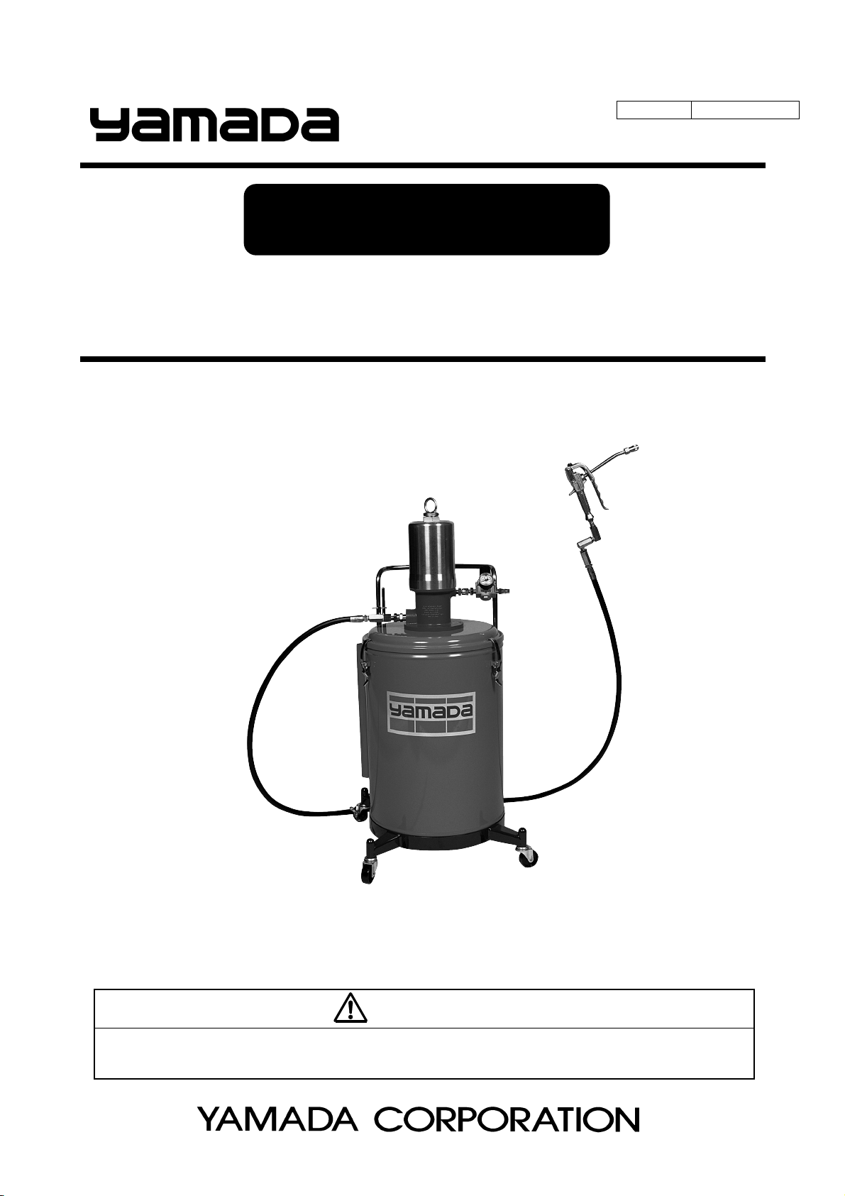
INSTRUCTION
GREASE LUBRICATOR
SKR- 110A50 MODEL No.880631
WARNING
Prior to operating this pump, be sure to read this operation manual for safety. After reading the manual, please
keep it on hand for future reference.
Page 2
- Preface
Thank you for purchasing a Yamada Pump. This machine is a portable type lubricator that is indispensable for grease
lubrication for machines and vehicles. This lubricator cannot be used for oil lubrication.
The applicable grease is limited to a type of NLGI No.2 or less in the normal operating conditions.
- If the lubricator is used in an extremely cold or low-temperature environment, the discharge volume will be
remarkably lowered.
- Silicone grease is not applicable.
- For Safe Operation
This manual describes the items that are important for the user to operate this product safely, correctly, and efficiently.
Before operating this product, read this manual thoroughly, in particular, “Warnings and Cautions” at the beginning of
this manual.
- Warnings and Cautions
For safe use of this product, be sure to note the following: In this document, warnings and cautions are indicated by
symbols. These symbols are for those who will operate this product and for those who will be nearby, for safe
operation and for prevention of personal injury and property damage. The following warning and caution symbols
have the meanings described below. Be sure to remember their meanings.
WARNING :
This indicates the existence of potential hazard which, if not avoided, will
result in death or serious injury.
1/2
CAUTION :
Furthermore, to indicate the type of danger and damage, the following symbols are also used along with those
mentioned above:
This symbol indicates a DON'T, and will be accompanied by an explanation on something you must not
do.
This symbol indicates a DO, and will be accompanied by instructions on something you must do in a
certain situation.
This indicates the existence of potential hazard which, if not avoided, may
result in bodily injury or in physical damage.
Page 3
- Precautions on Use
The following warnings and cautions are very important. Be sure to observe them.
WARNING
- If the material handled come into direct contact with or is splashed over your body, it could be harmful
to the eye or skin. Be sure to check the material handled, and when you work with it, put on a protective
gear (protective mask, glasses, safety gloves, etc.) depending on the degree of danger.
- Some types of grease may contain a carcinogenic material. Read the cautions for handling grease
given by the grease maker carefully when handling the grease.
- Gasoline is a high-volatility material. Do not use gasoline to clean the pump in any case, otherwise it
may cause ignition or explosion.
CAUTION
- Restriction on handling
The operator or administrator of this pump should not allow those who have no knowledge of the pump
to operate it.
2/2
- The maximum supply air pressure of this machine is 0.7 MPa. Using the machine with a supply air
pressure exceeding this limit will lead to death or bodily injury or physical damage due to machine
breakage. Be sure to adjust the supply air pressure below 0.7 MPa.
- After the end of daily work, at night, and on holidays, be sure to shut off the supply air to this machine to
release the gun so as to bleed the internal pressure.
Any secondary accident such as pollution of installation, due to pump operation driven by worn-away
packing or hose without shutting off the supply air, shall be attributable to the user’s responsibility.
- Do not operate the gun lever with the discharge port facing to another person during machine operation
in any case. A direct hit against the human body may result in an accident such as skin damage.
- During machine operation or after completion of movement, be sure to lock the caster brake for locking.
- When replacing any part at maintenance, be sure to stop the air supply to the machine to avoid having
fingers nipped because of a malfunction.
Page 4

Table of Contents
- Preface
- For Safe Operation
- Warnings and Cautions
- Precautions on Use
1. Names of Parts
1.1 Names of Parts .................................................................................................................... 1
1.2 Contents of Package ........................................................................................................... 1
2. Principles of Operation ......................................................................................................... 2
3. Preparations before Operation
3.1 Setting a Pail ....................................................................................................................... 3
3.2 Assembling the Equipment .................................................................................................. 3
3.3 Operating the Equipment ..................................................................................................... 4
4. How to Operate the Machine ............................................................................................... 5
5. Maintenance and Inspection
5.1 Troubleshooting and Corrective Measures .......................................................................... 6
5.2 Maintenance and Inspection ................................................................................................ 7
5.3 Disassembly and Assembly ................................................................................................. 8
5.3.1 Separating the air motor from the lower pump ................................................................ 8
5.3.2 Disassembling and inspecting the lower pump ............................................................... 9
6. Parts Disassembly Drawing and Parts List
6.1 SKR-110A50 (880631) ........................................................................................................ 10
6.2 Grease Gun (851985) .......................................................................................................... 10
6.3 Pump Ass’y (851779) .......................................................................................................... 11
7. Pump Specifications
7.1 Engineering Data ................................................................................................................. 12
7.2 Performance Curve ............................................................................................................ 12
7.3 Demensions ......................................................................................................................... 12
8. Limited Warranty .................................................................................................................... 13
Page 5
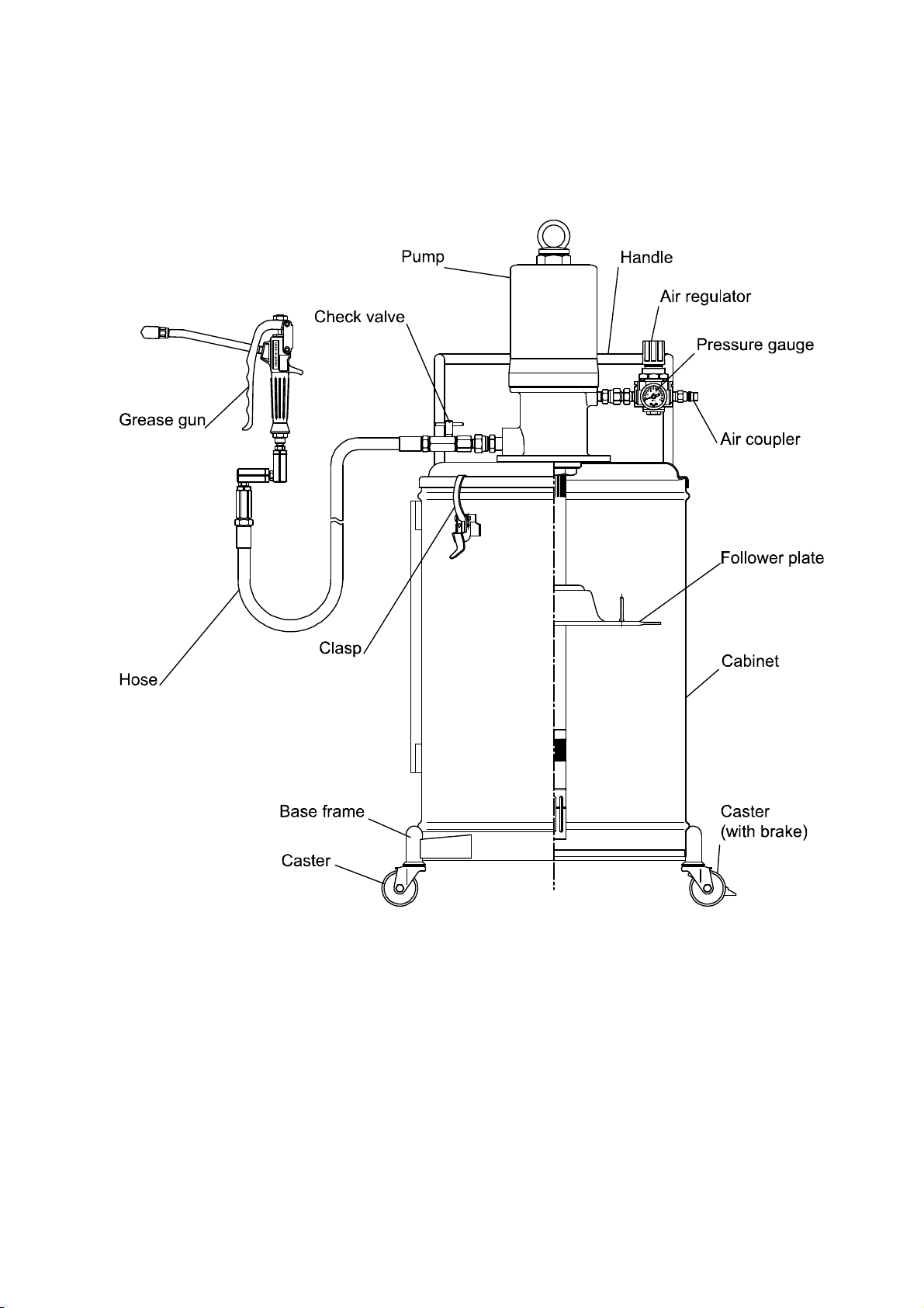
1. Names of Parts
1.1 Names of Parts
1.2 Contents of Package
The main devices and the accessories are packed in different cases.
Open the top part of the corrugated fiberboard case and check if the devices and cabinet are not damaged and if
accessories are all contained in the package.
1
Page 6
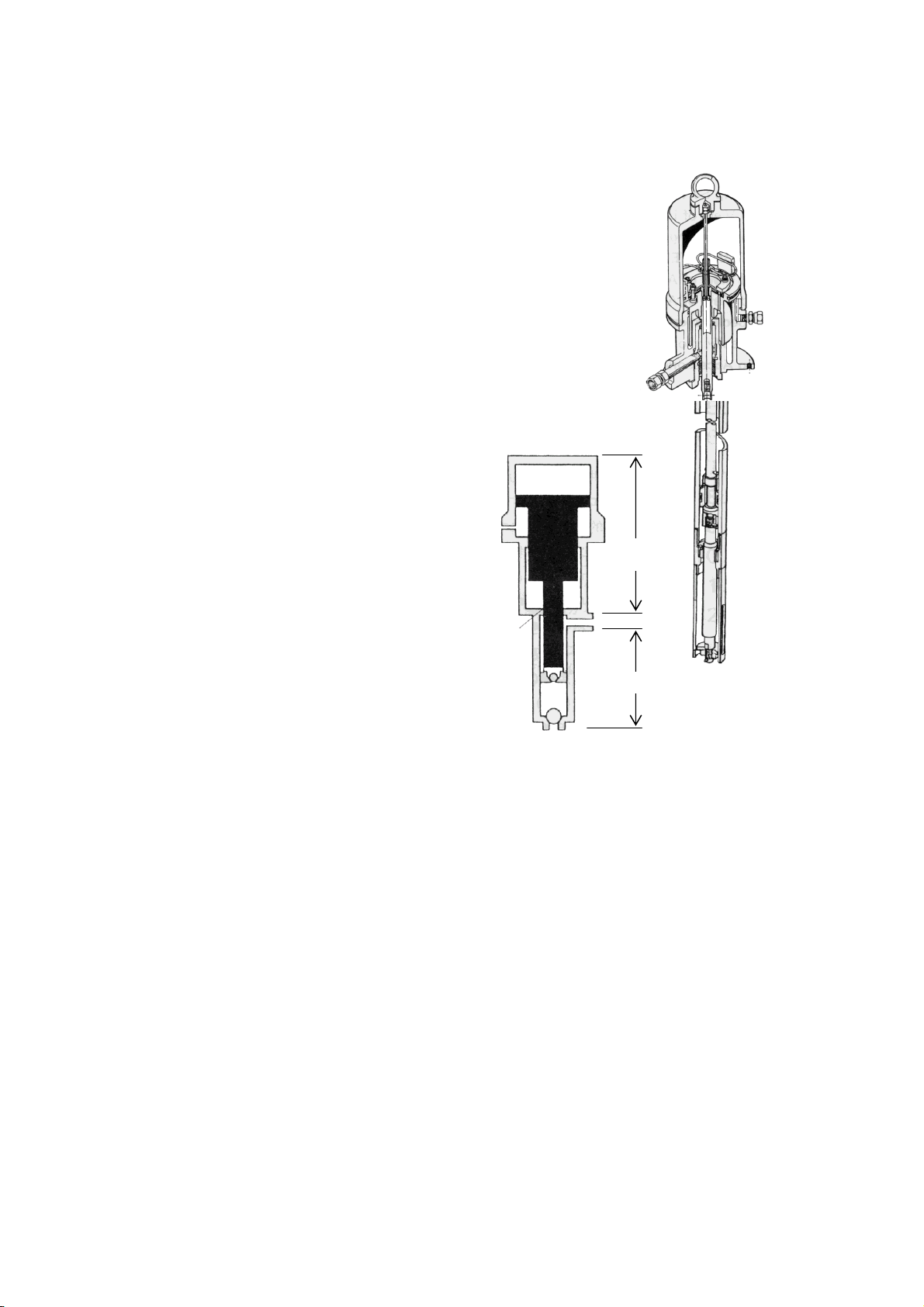
2. Principles of Operation
The Yamada Air-powered Pump is a reciprocating type that is driven by
compressed air. The pump consists of an air motor to drive the pump and a
lower pump to draw up the material as shown in the figure at right.
When compressed air is supplied from the compressor to the air motor, the
air piston starts its up/down motion by the function of the air switching
mechanism built in it.
This motion is transmitted to the piston of the lower pump by the connecting
rod that connects between the air piston of the air motor and the piston of the
lower pump, thereby giving the up/down motion to it.
When the up/down reciprocating motion of the piston of the lower pump is
performed, the material is sucked into the lower pump and fed out from the
discharge port by pressure.
Connecting
rod
Air
Motor
Lower pump
2
Page 7

3. Preparations before Operation
3.1 Setting a Pail(Fig. 1)
1) Release the 3 clasps on the top of the cabinet upward, and
the lid can be removed together with the pump.
2) Take out the follower plate in the cabinet.
<Note>
Take extreme care not to allow sand and dust to adhere on
the suction tube and follower plate of the pump Ass’y.
3) Prepare a new pail and remove its lid. Then, set the can in
the middle of the cabinet.
4) Set the attached follower plate on the top surface of the
grease in the set pail. (For the direction of the follower plate,
refer to Fig. 1.)
5) Place the follower plate on the grease horizontally and push
it down by rubbing it with a hand until the grease comes out
from the packing in the middle of the plate. (Fig. 2)
<Note>
When using the follower plate for the first time after
purchasing the product, pack grease beforehand in the
rear-side concave portion of the plate. This facilitates the
work. (Fig. 3)
6) Insert the suction tube in the pail so that the suction tube of
the pump Ass’y may pass in the middle of the follower plate,
put the lid on the cabinet, and fix the cabinet and the lid with
the 3 clasps.
<Note>
Take care not to blemish the packing of the follower plate by
the end of the suction tube.
3.2 Assembling the Equipment
Fig. 1
Fig. 2
Fig. 3
1) Install the attached high-pressure hose and the
high-pressure grease gun at the discharge port of the pump,
and then install the air regulator at the air supply port.
Clamp the connecting portion securely. (Fig. 4)
2) Install the attached air chuck on the air hose (for size 1/4,
separately available), and fix it with a hose band.
If the connecting air chuck for the compressor side is not
available, purchase it separately.
3
Fig. 4
Page 8

3.3 Operating the Equipment
CAUTION
- The maximum supply air pressure of this machine is 0.7 MPa. Using the machine with a supply air
pressure exceeding this limit will lead to death or bodily injury or physical damage due to machine
breakage. Do not set the supply air pressure over 0.7 MPa in any case.
1) Turn the knob of the air regulator counterclockwise for looseness, and then connect the air chuck to supply air.
<Note>
Using an air regulator permits adjusting the supply air pressure to the pump and reducing unnecessary pump
motion, thereby improving the work efficiency and extending the life of the pump.
When the knob of the air regulator is turned clockwise, the air pressure will be increased (the indicator of the
pressure gauge gradually goes from “0” to a larger number). When the knob is turned counterclockwise, the air
pressure will be reduced (the indicator of the pressure gauge goes back to “0”). In the normal operating condition,
the indicator of the pressure gauge is in the range of 0.3 to 0.5 MPa.
2) As the knob of the air regulator is gradually turned clockwise,
the pump is started when the supply air pressure reaches 0.2
or 0.3 MPa. The pump is operated for a while and the pump
and hose are filled with grease.
3) The first applied grease includes the internal air of the pump.
This is not a good condition.
Obtain a perfect condition by the next operation.
First open the check valve and operate the pump until
grease is discharged from a small hole under the check
valve. After grease is discharged in a perfect condition, close
the check valve. At this time, spread paper so that grease
may not come into touch with the hand, and dispose of the
discharged grease. (Fig. 5)
4) Set the supply air pressure to 0.5 to 0.7 MPa.
<Note>
The grease in which air is mixed is cloudy in white.
Fig. 5
4
Page 9

4. How to Operate the Machine
CAUTION
- The supply air pressure should be 0.7 MPa or less. If the primary pressure
is more than 0.7 MPa, adjust the pressure to 0.7 MPa or less.
- After the end of daily work or when the machine is not operated for a long
time, be sure to shut off the supply air and bleed the internal pressure of the
pump, hose, and gun.
- During machine operation or after completion of movement, be sure to lock
the caster brake for locking. (Fig. 6)
1) Wipe the grease nipple to be used for greasing cleanly. After that, push
the chuck at the end of the grease gun against the nipple to perform
chucking as vertically as possible. (Fig. 7)
2) Pull the gun lever to supply grease. When grease is normally injected, old
grease will be squeezed out from the groove or clearance near the nipple.
3) After completion of grease supply, release the gun lever. The pump will be
automatically stopped.
4) Remove the chuck at the end of the grease gun.
Since pressure is applied to the chuck, the head of the nipple may be
broken if it is suddenly pulled. Incline the chuck to bleed the internal
pressure, and the chuck can be easily removed. (Fig. 8)
5) After completion of greasing work, be sure to shut off the supply air of the
pump and bleed the internal air of the hose.
6) If the pump is suddenly started, it may be due to non- existence of grease
in the pail can or an air pocket produced. Stop the greasing work and
make a check.
7) Exchange the pail when the grease stopped coming out.
Fig. 6
Fig. 7
Fig. 8
5
Page 10

5. Maintenance and Inspection
5.1 Troubleshooting and Corrective Measures
If the pump operation becomes unstable or trouble is caused to its grease discharge during operation, make a check
according to the following procedure.
Symptom Cause Contents of inspection and corrective measures
The pump cannot be
operated.
The pump is
continuously
operated without
stop.
The pump operated
but the material is
not fed by pressure.
The pump can be
operated but the
discharge volume is
insufficient.
Check if the air regulator
is normally operated.
YES
Check if the valve on the
outlet on the pump side
is not closed.
NO
Remove the lower pump
and operate the air motor
independently.
inoperable
Check if the material
does not leak at the
exhaust port of the air
motor.
Check if there is any
open valve on the
material output side.
NO
When the outlet side is
closed, check if any leak
does not occur on the
pipe, connecting hose or
its connecting portion.
The material vessel is
empty.
Check if the supply air
pressure is not lowered.
check
check
operable
YES
NO
YES
YES
NO
Check if the valve in the
course of piping is not
closed.
Clogging occurs in the
connecting hose, pipe,
outlet valve, or gun.
The lower pump is faulty.
The air motor is faulty.
The packing seal of the
air motor is worn away.
The valve of the lower
pump or the packing is
worn away.
Check and re-supply, or
replace.
Increase the pressure up
to 0.7MPa by the air
regulator. At this time, the
grease volume does not
reach the specified level.
The valve seat surface of
the lower pump, the
packing is worn away or
clogging is caused by
dust or foreign
substances.
Ask for servicing the
lower pump and see
P.9.
Ask for servicing the
air motor.
The air supply volume
to the pump is
insufficient.
Replace the air hose
with a thicker one or
check the air
compressor.
6
Page 11

5.2 Maintenance and Inspection
For lubrication of the pump, perform oiling once every 10 days
with lubricating oil. (Fig.9)
Apply the lubricating oil as following.
1) Remove the air regulator.
2) Inject a few drops of lubricating oil (approx. 0.5 mL) into the
air supply port as shown in the figure at right. Use turbine oil
class 1 ISO (VG-32) or equivalent as the lubricating oil.
[Inspection]
The hose is a consumable part. Check it periodically. If any blemish or leakage is found, replace the hose little
earlier.
The packing and slide portion parts of the pump are worn away. Check and replace them once a year.
Fig. 9
CAUTION
- When washing parts, do not use such a liquid as corrodes aluminum, copper alloy, iron, etc.
7
Page 12

5.3 Disassembly and Assembly
When the pump operation becomes defective or stops, do not disassemble the pump thoughtlessly but judge the
condition carefully by referring to the item pertaining to <Troubleshooting and Corrective Measures>.
The air motor that is not brought into direct contact with the material becomes defective rarely, so it does not need to
be disassembled. If disassembly is required, ask the dealer to disassemble the air pump.
WARNING
- Gasoline is a very volatile fuel. Do not use it for cleaning the pump in any case, otherwise it may lead
to ignition or explosion.
- When disassembling and checking the pump, be sure to stop the supply air and open the outlet valve
to release the internal pressure of the pump beforehand.
5.3.1 Separating the air motor from the lower pump
1) Shut off the air that is supplied to the pump and bleed the
internal pressure of the pump.
2) Remove the high-pressure hose and the air hose from the
pump.
3) Release the 3 clasps on the top of the cabinet upward, and
take out the pump Ass’y together with the lid.
4) Unscrew the 5 bolts (on the rear side of the lid) that fix the
pump Ass’y and the lid and separate the pump Ass’y from
the lid.
5) Fix the air motor body of the pump on the vise and set a
pipe wrench on the knurling section of the suction tube of
the lower pump and unscrew it. (Fig. 10)
<Note>
The air cylinder is easily damaged.
Do not fix it on the vise in any case.
6) Pull out the suction tube, and the connecting stud that connects the piston rod of the air motor becomes visible.
Pull out the spring pin of the connecting section and unscrew the connecting stud or the lower pump, and the air
motor can be separated from the lower pump. (Fig. 10)
Fig. 10
8
Page 13

5.3.2 Disassembling and inspecting the lower pump
1) Fix the suction tube on the vise and set a pipe wrench on
the booster cover. Unscrew the suction tube and remove
the spring pin, nut, and shovel. (Fig. 11)
2) Likewise, set a pipe wrench on the valve case and unscrew
it. The valve stopper and the foot valve (a part of the
plunger Ass’y) can be removed.
3) Pull out the plunger rod from the suction tube by holding it.
The piston and connecting rod Ass’y can be pulled out.
(Fig. 12)
4) Pull out the spring pin that connects between the
connecting rod and the plunger, and take out the plunger.
Wash the plunger and check it for blemish and wear.
<Note>
The plunger is an assembly for mating with the valve. Insert
the foot valve in the plunger, and check if it can smoothly
slide. These two parts, if they are blemished, must be
replaced as an assembly.
5) The portions with which the lower part of the piston and the
connecting stud come into contact form a seat surface.
Check them for blemish.
6) Wash and check each disassembled part. If any blemish or
wear is found, replace the part with a new one.
7) For assembling, reverse the disassembling procedure.
(Fig. 13)
In particular, perform assembling taking care about the
directions of the valve seat and the foot valve.
[Inspection]
The air motor is not easily adjusted at assembly. If an air
motor failure is found at maintenance and inspection, ask
the dealer to repair the air motor.
Fig. 11
Fig. 12
Fig. 13
9
Page 14

6. Parts Disassembly Drawing and Parts List
6.1 SKR-110A50 (880631)
6.2 Grease Gun (851985)
No. Parts No. Descriptions Q’ty
1 851779 Pump Ass ’y 1
2 851985 Grease gun 1
3 695034 Hi-pressure hose 1
4 800431 Check valve 1
5 830112 Clasp 3
6 701747 Pin 3
7 680710 Snap pin 3
8 830745 Cabinet 1
9 830746 Base frame 1
10 682925 Air regulator 1
11 682924 Gauge 1
12 680743 Air coupler 1
14 705625 Lid 1
15 803481 Follower plate 1
16 680136 Caster 2
17 681767 Caster(wit h brake) 2
No. Parts No. Descriptions Q'ty
1-1 683201 Rivet 2
1-2 711351 Link 1
1-3 711444 Retaining nut 1
1-4 772160 Paking 2
1-5 711357 Rod 1
1-6 711352 Body 1
1-7 630314 Ball 1
1-8 711445 Spring retainer 1
1-9 711446 Spring 1
1-10 640011 O ring 1
1-11 710971 Union 1
1-12 711750 Bolt 1
1-13 627641 Nut 1
1-14 711354 Lever 1
1-15 713638 Was her 1
2 804911 Nozzle 1
3 685728 Cap 1
4 802910 Swivel joint Ass’y 1
No.1-1, 1-2, 1-6 and No.1-14 are undiss olution.
■
10
Page 15

6.3 Pump Ass’y (851779)
<Note>
- If disassembly is required, ask the dealer to disassemble the air motor.
- As for the specialist of the dissolution, refer to the instruction manual.
(Separately APP 001 U : Maintenance Manual for Grease Pump )
No. Parts No. Descriptions Q’ty
1 802497 Air motor Ass ’y 1
2 632773 Spring pin 4
3 710745 Conn. rod 1
4 710736 Soc ket 1
5 710619 Piston 1
6 771367 Bac k-up ring 2
7 682926 O-ring 1
8 710737 Connecting rod 1
9 802499 Plunger Ass’y 1
10 632032 Cott er pin 1
11 710739 Cylinder 1
12 682922 O-ring 1
13 701600 Valve stopper 1
14 710620 Valve case 1
15 710622 Shovel 1
16 627012 Nut 1
17 710621 Booster cover 1
11
Page 16

7. Pump Specifications
7.1 Engineering Data
Type SKR-110A50
Model No. 880631
Pump ratio 50 × 1
Material
connection
Air connection Air inlet G 1/4
Operating range
Noise dB(A) Max. 80.5
Operating temperature range
No. of cycle / liter 89
Dimensions (mm) 480×480×953
Mass (kg) 39
Accessories
Above conditions
Air pressure 0.7 MPa
Material Grease NLGI-No.1
Oil Temperature 18.4 ℃
7.2 Performance Curve (only the pump) 7.3 Demensions
Discharge port G 1/4
Suction port
Supply air pressure
0.3~0.7 MPa
Hi-pressure Hose (695034) 1/4×2.5m
Grease Gun (851985)
Air regulator with coupler (802553)
Follower plate (803481)
Pump outlet pressure 32~35 MPa
Delivery 3.3 L/min (2.94kg)
Cycle 276 cycle/min
Air consumption 930 L/min(ANR)
-
0.3 ~ 0.7 MPa
0~80 ℃
<Note>
The continuous pump operation should be avoided
if the desired delivery is in the range shaded in the
figure below.
953
480
480
12
Page 17

8. Limited Warranty
● If an abnormality occurs during normal operation in accordance with the operating instructions and other operating
cautions within the warranty period (12 months after date of purchase) that can be attributed to a manufacturing
defect, the defective parts of this product will be serviced or the product will be replaced free of charge. However,
this warranty will not cover compensation for incidental damage or any malfunction listed below.
1. Warranty period
This warranty will be valid for a period of 12 months after the date of purchase.
2. Warranty
If, during the warranty period, any of the material of the genuine parts of this product or the workmanship of this
product is found defective, and is so verified by our company, the servicing cost will be fully born by our company.
3. Exclusion
Even during the warranty period, this warranty does not cover the following:
1) Malfunction arising from use of parts other than manufacturer-specified genuine parts
2) Malfunction arising from misuse or operating errors, or lack of storage or maintenance care
3) Malfunction arising from use with a fluid that may cause corrosion, inflation or dissolution of the component
parts of the product
4) Irregularity arising from repair made by other than by our firm, our regional office, dealer or authorized service
personnel
5) Malfunction arising from modification of the product by other than authorized service personnel
6) Wear and tear of parts that must be regularly replaced in the course of normal operation, such as packings,
O-rings, balls, and valve seats
7) Malfunction and/or damage due to transportation, moving or droppage of the product after purchase
8) Malfunction and/or damage due to fire, earthquake, flood or other force majeure
9) Malfunction arising from use of compressed air that contains impurities or excessive moisture, or use of
gases or fluids other than the specified compressed air
10) Malfunction arising from use with a fluid that causes excessive abrasion or use of lubricating oil other than
that specified for this product
Furthermore, this warranty does not cover the rubber parts, or other parts that are subject to wear in normal
operation, used in this product and its accessories.
4. Parts
Parts for this product will be kept available for 5 years after discontinuation of production. Once 5 years have
elapsed after close of production, availability of parts for this product cannot be guaranteed.
13
Page 18

YAMADA
INTERNATIONAL DEPARTMENT
1-1-3 Minami Magome, Ohta-ku, Tokyo 143-8504, Japan
PHONE : +81-(0)3-3777-0241
FAX : +81-(0)3-3777-0584
YAMADA
AQUAMARIJNSTRAAT 50, 7554 NS HENGELO (O), THE NETHERLANDS
PHONE : 31-(0)-74-242-2032
FAX : 31-(0)-74-242-1055
CORPORATION
EUROPE B.V.
201109 OSA010U
 Loading...