

Page 1
Doc. No. APP 037U-04
INSTRUCTION
OIL PUMP
(110 type series)
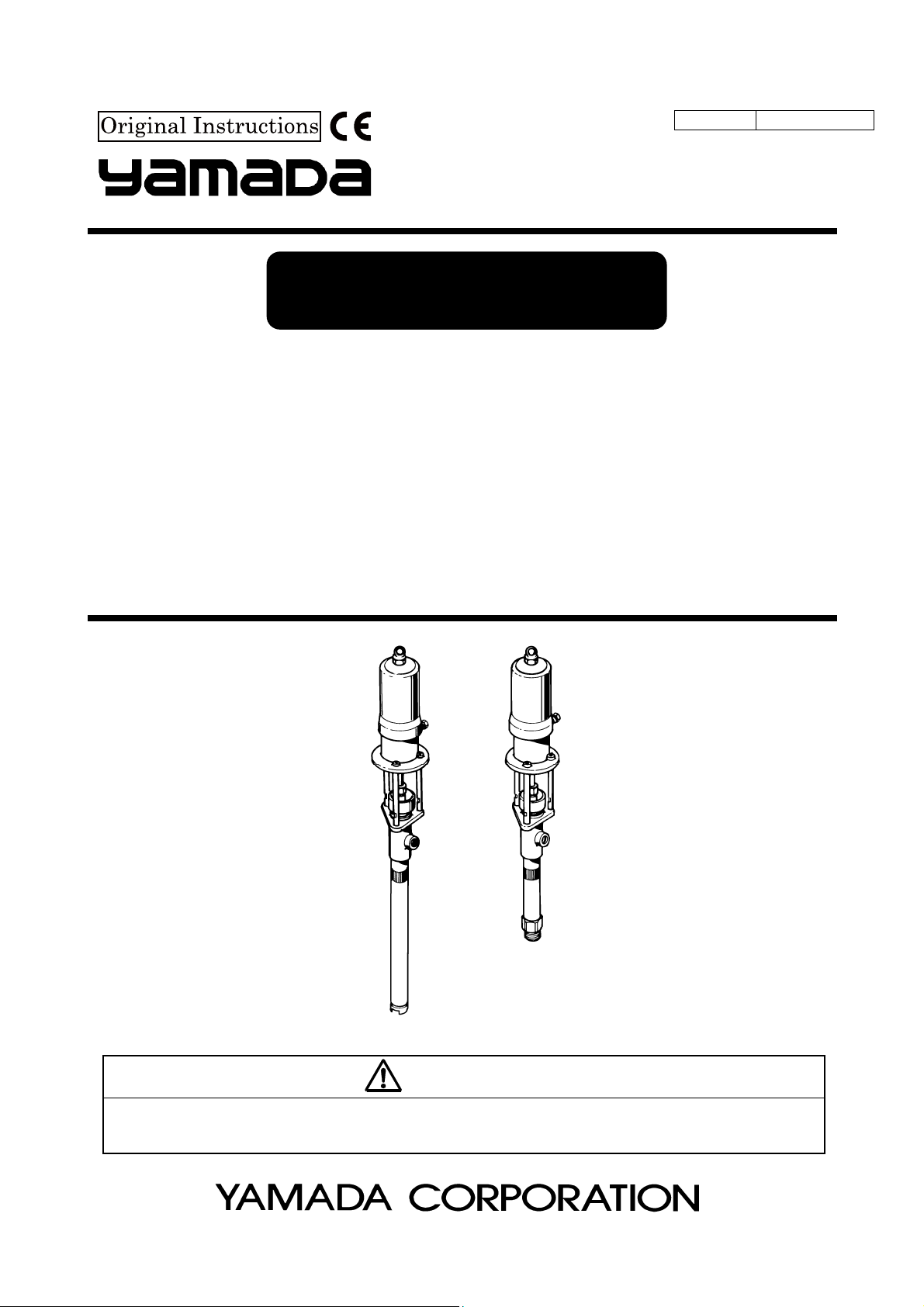
PD-110B5 MODEL No.851829
SH-110B5 MODEL No.851830
DR-110B5 MODEL No.851831
SH-110B5SUS MODEL No.851832
DR-110B5SUS MODEL No.851833
WARNING
Prior to operating this pump, be sure to read this operation manual for safety. After reading the manual, please
keep it at hand any time for your quick reference.
Page 2

- Preface
Thank you very much for purchasing Yamada Pump. This 110 series 5x1 ratio pump is suitable for delivering paint,
lacquer, thinner, anti-rust, oil…etc. Also, stainless steel pumps (SUS) are well adapted especially for feeding or
supplying chemicals and food since stainless steel and fluorocarbon resin are used in wetted parts material.
- For Safe Operation
This document describes the items that are important for the user to operate this product safety, correctly, and
efficiently. Before operating this product, read this manual thoroughly, in particular, “Warnings and Cautions” at the
beginning of this manual, with a good understanding of its contents. Keep this manual carefully in an easy-to-access
place so that the user may refer to it whenever necessary.
- Warnings and Cautions
To use this product safely, be sure to observe the contents of the following description. In this manual, warnings and
cautions are indicated by using symbols. These symbols are intended to prevent death or serious injury that may be
caused to the operator or those who are around the product and damage that may be caused to the articles that are
around the product, as well as to use the product safely and correctly. Each symbol is indicated and has a meaning as
shown below. Read the description with a good understanding of its contents.
WARNING :
This indicates the existence of potential hazard which, if not avoided, will
result in death or serious injury.
1/3
CAUTION :
To indicate the contents of danger and damage, the following symbols are used together with the above indications.
This symbol indicates an act that is prohibited (prohibition). The concrete contents of prohibition are
indicated by the side of the indication.
This symbol indicates the contents that must be observed. The concrete contents of observance are
indicated by the side of the indication.
This indicates the existence of potential hazard which, if not avoided, may
result in bodily injury or in physical damage.
Page 3
- Precautions on Use
The following warnings and cautions are very important. Be sure to observe them.
2/3
WARNING
- Keep your face away from the exhaust and discharge ports. Material may suddenly come out. There is
a possibility of losing eyesight if it strikes eyes.
- Gasoline is a high volatile fuel. Do not use it to clean the pump in any case, otherwise ignition or
explosion may be caused.
- Keep your fingers away from each port to avoid injury from moving parts.
- Modification of this pump may lead to death, bodily injury, or a failure. Do not modify it in any case
because it involves a risk.
- The operator and maintenance engineer should read the operation manual thoroughly before operating
the pump and performing maintenance in respect of this pump.
- Always wear proper safety equipments(facemask, ear plugs, and safety shoes, etc.) when installing,
operating and disassembling the pump.
- Make ground connection when working with flammable material or in explosive atmosphere. Rapid
pumping of material can result in static electrical charge.
Also, be sure to provide proper ventilation where a flammable atmosphere may exist.
- Execute the daily checkup.
- Use this pump according to the product specification.
- Attach a valve(for stop in emergency) or regulator to the air supply pipe to keep supply air pressure
under 0.7MPa.
- Discontinue it when you feel a hazard or abnormality during the work. And correspond according to the
troubleshooting.
- Stop pump operation immediately when a drum becomes empty. Running the pump dry will cause
excessive vibration, resulting in reduction of pump life and damage to other equipment. Be especially
careful when pumping explosive material. Mixture of an air and vaporized material can explode. If there
is any possibility of running dry, install a dry-run protection device like a liquid level control.
- Before maintenance operation, be sure to stop air from being supplied to the pump, and release the
internal pressure (both air and material) of the pump. There is danger such as spouting of the material
when the maintenance work is done with air supplied.
- Do not discharge material directly onto the ground. Dispose of harmful materials according to the
requirements specified in MSDS or local regulations. Also, dispose of pump according to the local
regulations after removing residual material from inside pump. (Please contact industrial waste disposal
service.)
- (SH type only)If using a wall mount bracket for installation, the wall must be strong enough to withstand
vibration of the pump.
- Before starting pump operation, retighten the bolts or connection parts of the pump.
Page 4
3/3
CAUTION
- Keep hands and fingers away from the pump during operation to avoid injury from moving parts.
- Use pump for the material suitable for the specification. Parts may be corroded and material leak from
the damaged parts can lead to environmental pollution. Also, follow handling notes (MSDS) of the
manufacturer about the handling of the material used.
- Take fall-prevention measures if using a slim or light tank. Risk of falling will be increased due to shift in
center of gravity caused by change in the material level in a tank.
- Take protective measures against rainwater and dust. It is likely to lead to the pollution of the material.
- Be very careful about the edge of the pump when you lift the pump. Your hands might be injured.
- Be very careful about your posture when installing the pump. Back injury may be caused by lifting the
pump.
- Do not touch the surfaces of the pump and the hose when pumping high-temperature material. Risk of
burns exists.
- Stop the air supply source after the end of work when not using this pump for a long time such as
nighttimes and holidays. Also, open the valve of the exhalation port and liberate pressure in the pump
and the hose. There is a possibility of polluting facilities because of the damage of the hose and the
leakage of the valve. Such a secondary disaster becomes a responsibility on the user side.
- (DR type only) Place a drum on a flat, level surface to position pump horizontally against a ground.
Operating the pump on a slope may cause a fall or tip-over due to shift in center of gravity caused by
change in the material level.
- (DR type only) Material remaining inside or on the surface of the pump may spill out by inserting or
removing the pump into /from a drum. Be very careful not to get your clothing dirty.
Page 5

Table of Contents
- Preface
- For Safe Operation
- Warnings and Cautions
- Precautions on Use
1. Names and Materials of Parts
1.1 Names and Materials of Parts ............................................................................................. 1
1.2 Contents of Package ........................................................................................................... 1
2. Principle of Operation ........................................................................................................... 1
3. Installation
3.1 Installing drum type (DR) pump ........................................................................................... 2
3.2 Installing stubby type (SH) pump ....................................................................................... 2
3.3 Installing delivery hose ........................................................................................................ 2
3.4 Connecting supply air .......................................................................................................... 2
4. Operating Method................................................................................................................... 3
5. Maintenance and Inspection
5.1 Troubleshooting and Corrective Measures .......................................................................... 4
5.2 Maintenance and Inspection................................................................................................ 4
6. Disassembly and Assembly................................................................................................. 5
7. Parts Disassembly Drawing and Parts List
8. Specification
9. Limited Warranty .................................................................................................................... 11
.................................................................... 6
............................................................................................................................ 9
Page 6
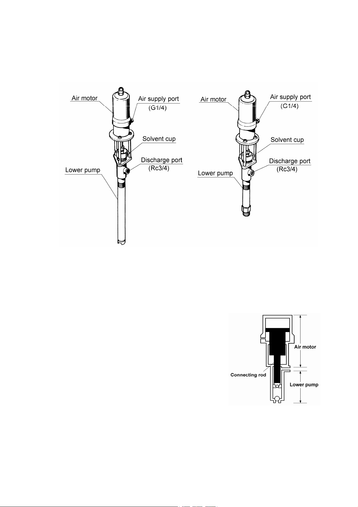
1. Names and Materials of Parts
1.1 Names and Materials of Parts
851829, 851831, 851833 851830, 851832
1.2 Contents of Package
This machine is packaged in a corrugated fiberboard case. Open the top lid of the corrugated fiberboard case and
check the machine for damage.
2. Principle of Operation (Fig. 1)
The Yamada air-powered pump is a reciprocating type pump that is driven
by compressed air. The pump consists of an air motor section to drive the
pump and a lower pump to pump up the material as shown in the
Fig. 1 at right.
When the compressor feeds compressed air to the air motor, the air piston
starts up/down reciprocating motion by means of the function of the built-in
air changeover mechanism.
This function is transmitted to the piston of the lower pump by the
connecting rod that connects the air piston of the air motor to the piston of
the lower pump, and gives up/down reciprocating motion to it.
The material is pumped into the lower pump by the up/down reciprocating
motion of the piston of the lower pump and discharged by pressure from
the discharge port.
Fig. 1
1
Page 7

3. Installation
3.1 Installing drum type (DR) pump
1) Use the drum cover (optional) and install on the open type drum.
(Fig. 2)
3.2 Installing stubby type (SH) pump
1) Install the pump on the mounting bracket (optional) or panel unit
(option) and fix on the flat wall.
2) Connect the suction hose assembly (optional) to the pump.
(Fig. 3)
<Note>
When the pump is not used for circulation pump,
plug the material outlet (Rc3/4) of the pump.
3.3 Installing delivery hose
1) Install the union adapter (option) and delivery hose (option) at
the material outlet of the pump. Screw them firmly. Use seal
tape for connection.
2) Connect the hose to the piping.
<Note>
- When connecting to the long-distance piping, install the high- pressure
ball valve at the end of the piping. (Fig. 3)
- When using the pump for paint circulation, install pressure valve and
then connect the return hose to the pump.
Fig. 2
Fig. 3
CAUTION
- Do not connect the piping directly to the pump. Vibration caused by direct connection may result in
damage to the piping or generation of noise. As for a drum type, it may also be the cause of difficulty in
changing a drum and inconvenience of pump maintenance. Be sure to use a flexible hose to connect
the piping to the pump.
3.4 Connecting supply air
1) Install the air regulator (option) at the air inlet of the pump.
2) Connect the supply air piping to the inlet of the air regulator.
<Note>
- Install the air valve at the end of the supply air piping for convenience of pump operation.
Before installing the air regulator, be sure to adjust it to “0” position.
- 0.3MPa~0.5MPa is the proper air pressure for normal operation.
2
Page 8

4. Operating Method
The pump is equipped with the solvent cup. To protect the plunger rod and packing from damage caused by dried and
stiffed pumping material, pour solvent or suitable lubricant to 2/3 level of the cup. (Fig. 4)
CAUTION
- Do not bring a face close to the exhaust port of the operating pump in any case. Because of the high
exhaust pressure, water may be frozen and it could cause injury.
- Do not put hands in the 3 studs that connect the air motor to the lower pump. Hands may be caught by
the plunger in reciprocating motion. It may result in an injury.
- The maximum operating air pressure of this machine is 0.7MPa. Using the machine exceeding 0.7MPa
may result in a bodily injury or property damage. Do not operate the machine over 0.7MPa. If the air
line is 0.7MPa, reduce the air line to 0.7MPa or less by using the air regulator.
- Regarding a secondary accident such as hose damage that may be caused by not shutting off the air
supplied to the hose or floor contamination due to a leak from the valve or gun after completion of the
work or at night, the responsibility rests with the user side.
- When the pump causes a malfunction or stop operation, do not disassemble the pump thoughtlessly.
Make sure to disassemble only necessary parts, referring to <5.1 Troubleshooting and Corrective
Measures> and judging the situation properly.
1) Turn the knob of the air regulator clockwise to supply air into the pump. When the supply air pressure reaches
0.15 to 0.2MPa, the pump starts to operate. The pointer of the pressure gauge indicates the supply air pressure.
2) W hen air is supplied, the pump is operated for a while to fill the hose, pipe, and gun with oil, and then stopped
automatically. If the pump is continuously operated without stop, leak may have occurred in any connecting portion
of the hose, pipe, or gun. Stop the air supply and make a check.
3) Operating the gun lever at the end of the delivery hose discharges oil. When the lever is pulled, the valve is
opened and the pump is automatically operated to discharge oil. When the lever is reset, the valve is closed to
stop the oil discharge and the pump is also stopped.
4) Adjust the supply air pressure according to the application. Usually, the operating pressure should be 0.3 to
0.5MPa. In particular, when the pump is used for feeding oil, the discharge volume differs depending on the piping
length and oil viscosity. Adjust the supply air pressure to your desired level.
5) After completion of the work, be sure to stop the supply air to the pump.
<Note>
- After completion of the work or when the pump is not operated
for a long time, keep the plunger rod bottom position and soaked
into the solvent cup to prevent damage on the packing by dried
material that stuck on the plunger rod. (Fig. 4)
- If the oil in the drum has run out, the pump will be operated at a higher
speed without oil. This may have an adverse effect on life of pump.
Stop the pump operation at once and replace the drum to the new one.
Fig. 4
3
Page 9

5. Maintenance and Inspection
5.1 Troubleshooting and Corrective Measures
Symptom Contents of inspection Corrective measure
The pump fails to start.
The pump fails to stop. - Check if the pump cannot be stopped when the
The pump is operated
but does not feed the
material by pressure.
The pump is operated
but the pressure and
flow rate are insufficient.
5.2 Maintenance and Inspection
- Check if the air regulator is normally operated.
- Check if the valve in the course of the pipe is not
closed.
(Remove the delivery hose at the pump-side outlet and
operate the pump.)
If the pump is operated, the delivery hose, pipe, or
outlet valve (gun) is clogged, or the operating
pressure is low.
If the pump is not operated, the pump is defective.
(Separate the lower pump and operate the pump with
only the air motor.)
If the pump is operated, the lower pump is defective.
If the pump is not operated, the air motor is defective.
material outlet side remains open.
- If the outlet side is closed, check if any leak occurs at
the pipe, delivery hose, or each connecting portion.
- Check if the air bleed valve or bleeder valve remains
open.
- Check if there is no material.
- Loosen the air bleed valve to bleed the air staying
under the inductor plate and tighten the valve again.
- If the pump cannot be operated, open the bleeder
valve. When the material comes out, tighten the valve
again.
If the material is not fed, disassemble the check valve
and clean and check the ball seat surface and spring.
- The pump cannot be operated yet, the pump is
defective.
- Check if the supply air pressure is insufficient.
- Check if the packing of the air valve is not worn away.
Pressure check.
(0.15 to 0.7MPa)
Inspection
Repair service for
the lower pump
Repair service
Inspection
Replenishment
Inspection
Inspection
Disassembly and
inspection
Repair request for
the lower pump
Pressure check
Repair request for
the lower pump
[Oiling]
For lubrication of the pump, perform oiling with a lubricant once every 10 days.
Apply the lubricant as follows.
1) Remove the air regulator.
2) As shown in the Fig. 5 at right, inject drops of lubricant (approximately 0.5mL)
into the oil cup. Use turbine oil first class ISO (VG-32) as the lubricant.
[Inspection]
The packing and parts around slide portion of the pump are worn away. Check
and replace them once a year.
[Daily check]
Before starting pump operation, retighten the bolts or connection parts of the pump. (Fig. 6)
4
Fig. 5
Fig. 6
Page 10

6. Disassembly and Assembly
CAUTION
- Gasoline is a high volatile fuel. Do not use it to clean the pump in any case, otherwise ignition or
explosion may be caused.
- Before disassembling and inspecting the machine, be sure to stop the supply air and open the outlet
valve to release the internal pressure of the pump.
- When cleaning pump parts, do not use a liquid that may corrode aluminum, copper ally, iron, etc.
[Separation of the air motor and the lower pump]
1) Shut off the air supply and release the pressure inside of
the pump.
2) Remove the air hose and delivery hose.
3) Remove the pump and let the material out from the
suction tube. The material inside of the suction tube can
be out by pushing the ball at the foot valve.
4) Grip the air motor part in a vise.
<Note>
The air cylinder is easily damaged. Do not fix it on the
vise in any case.
5) Loosen the lock nut.
6) Pull the lower pump and unscrew the cap nut that
connects the connecting rod and plunger rod. Then the
lower pump can be separated from the air motor.
(Fig. 7)
[Disassembling the lower pump]
Disassembling the foot valve
7) Grip the knurling part of the suction tube on a vise. Set a
wrench on the foot valve and unscrew it to remove the
suction tube. (Fig. 7)
8) Remove the stopper pin at the foot valve and the ball
and wash it. If scratch or ware is found on the ball and
the seat, replace with new parts. (Fig.11)
Disassembling the intake valve
9) Grip the body of the lower pump on a vise. Set a pipe
wrench on the knurling part of the suction tube and
unscrew it. (Fig. 7)
10) Remove the stopper pin that connects the connecting
rod and the plunger rod and loosen the connecting rod
screw.
<Note>
Be sure to set a wrench on the two flats cut of the
plunger rod. Placing a wrench on a slide portion of the
rod could cause damage and trouble.
Fig.10
Fig.11
Fig. 7
Fig. 8
Fig. 9
Fig.11
5
Page 11

11) Grip the housing on a vise. Set a wrench on the valve seat and unscrew it to remove the ball and L packing … etc.
If scratch or ware is found on them, replace with new parts. (Fig. 9)
12) The housing and the stud do not need to be disassembled usually. If disassembling them, beware to adjust the
clearance between the stud and the ball 4~5mm when reassembling. (Fig.10)
Disassembling the V packing
13) Grip the delivery manifold in a vise and remove the solvent cup by a hook wrench.
14) Remove the bushing. Then the packing gland and V packing can be removed. (Fig. 8)
15) Wash and check each part. If scratch or wear is found, change to new parts.
16) To reassemble after checking take opposite procedure of disassembling.
[Disassembling the muffler]
The silencing effect of the muffler at the exhaust port is halved by
clogging caused by long-term use. Disassemble and inspect it
periodically.
1) Remove the stop ring with stop ring pliers. The muffler and plate
can be taken out. (Fig.12)
2) Clean and inspect each part (in particular, check the plate for
clogging). If any wear is found, replace the part.
[Disassembling the air motor]
The air motor is hard to adjust at assembly. If the air motor is judged to be defective in the item pertaining to
<5. maintenance and inspection>, ask the dealer or our business office to repair it.
Fig.12
7. Parts Disassembly Drawing and Parts List
■851829 PD110B5 ▪ Parts Disassembly Drawing
■851830 SH110B5
■851831 DR110B5
■851832 SH110B5 SUS
■851833 DR110B5 SUS
851829 PD110B5 851830 SH110B5
851831 DR110B5 851832 SH110B5 SUS
851833 DR110B5 SUS
・Parts List
No. Description Q'ty
1 802571 Air motor 1
2 640006 O ring 1
3 632773 Spring pin 1
4 701565 Connecting rod 3
5 631422 Spring lock washer 3
6 627045 Nut 3
7 802575 802576 802577 802578 802579 Lower pump 1
851829
PD110B5
851830
SH110B5
Part No.
851831
DR110B5
851832
SH110B5 SUS
851833
DR110B5 SUS
6
Page 12

■802575, 802576, 802577 Lower Pump
▪ Parts Disassembly Drawing ・Parts List
802575
802577
802576
No. Description Q'ty
802575 802576 802577
7-1 710794 Connecting rod 1
7-2 830083 Solvent cup assembly 1
7-3 700350 Cap nut 1
7-4 701537 Plunger 1
7-5 701529 Bushing 1
7-6 830082 Body assy 1
7-7 701530 Packing gland 1
7-8 770150 V packing 6
7-9 701531 Packing gland 1
7-10 640135 O ring 1
7-11 704583 704584 Suction tube 1
7-12 701552 704155 Connecting rod 1
7-13 640012 O ring 1
7-14 632774 Spring pin 1
7-15 627016 Nut 1
7-16 701554 Housing 1
7-17 630334 Ball 1
7-18 701553 Valve seat 1
7-19 770233 Revolving stopper 1
7-20 701533 Toothed lock washer 2
7-21 701534 Washer 2
7-22 640131 O ring 1
7-23 701532 Back up washer 1
7-24 770151 L packing 2
7-25 701556 Pin 1
7-26 630341 Ball 1
7-27 640134 O ring 1
7-28 704587 704586 704587 Foot valve 1
Part No.
7
Page 13

■802578, 802579 Lower Pump (stainless)
▪ Parts Disassembly Drawing ・Parts List
No.
7-1 710803 Connecting rod 1
7-2 702283 Cap nut 1
7-3 830200 Solvent cup assembly 1
7-4 770234 Sleeve 1
7-5 702278 Packing gland 1
7-6 770231 U ring 4
7-7 702279 Packing gland 1
7-8 709290 Suction body 1
7-9 702285 Plunger 1
7-10 770235 Packing 1
7-11 705288 705287 Suction tube 1
7-12 680177 Spring pin 1
7-13 702290 703815 Connecting rod 1
7-14 628016 Nut 1
7-15 702286 Housing 1
7-16 630434 Ball 1
7-17 770233 Revolving stopper 1
7-18 702280 Valve seat 1
7-19 770501 L packing 2
7-20 770236 Back up washer 1
7-21 702287 Piston body 1
7-22 702288 Foot valve 1
7-23 705336 Pin 1
7-24 630442 Ball 1
7-25 770237 Packing 1
7-26 702289 703816 Foot valve 1
Part N o.
802578 802579
Description Q'ty
802579 802578
8
Page 14

g
g
g
g
g
8. Specification
■Specification
TYPE
MODEL No.
PUMP RATIO (NOMINAL)
FLUID
CONNECTION
AIR CONNECTION SUPPLY PORT
OPERATING AIR PRESSURE
MAXIMUM
OPERATING NOISE
AMB. TEMP.
RANGE
STROKE (NOMINAL)
DISCHARGE VOLUME per CYCLE *3
MAXIMUM DISCHARGE PRESSURE
WEIGHT
*1 Measurement method of A-weighted sound pressure level is based on ISO 1996.
*2 Measurement method of A-weighted sound power level is based on ISO 3744.
*3 Discharge volume (per cycle) varies according to use conditions.
SUCTION PORT R 1-1/2 R 1-1/2
DISCHARGE PORT
A-WEIGHTED SOUND
PRESSURE LEVEL *1
A-WEIGHTED SOUND
POWER LEVEL *2
ENV. TEMPERATURE
MATERIAL TEMP.
PD-110B5 SH-110B5 DR-110B5 SH-110B5 SUS DR-110B5 SUS
851829 851830 851831 851832 851833
98 mL
14.1 k
12.0 k
5 x 1
Rc 3/4
G 1/4(F) (Union Adapter)
0.3 ~ 0.7 MPa
90 dB
101 dB
0 ~ 60 ℃
0 ~ 80 ℃
60 mm
3.5 MPa
17.0 k
15.0 k
100mL
16.0 k
■Performance Curve
<Note>
The continuous pump operation should be avoided if the desired delivery is in the range shaded in the figure
below.
PD-110B5・SH-110B5・DR-110B5 SH-110B5 SUS・DR-110B5 SUS
9
Page 15

■Dimension
851829
851831
851833
851830
851832
Model No. A (mm) B (mm)
851829 843 523
851830 861 541
851831 1180 860
851832 857 538
851833 1229 909
Pump mounting hole layout
10
Page 16

9. Limited Warranty
This product is shipped to customers only after meeting strict inspection standards. If an abnormality occurs during
normal operation in accordance with the operating instructions and other operating cautions within the warranty period
(12 months after date of purchase) that can be attributed to a manufacturing defect, the defective parts of this product
will be serviced or the product will be replaced free of charge. However, this warranty will not cover compensation for
incidental damage or any malfunction listed below.
1) Warranty period
This warranty will be valid for a period of 12 months after the date of purchase.
2) Warranty
If, during the warranty period, any of the material of the genuine parts of this product or the workmanship of this
product is found defective, and is so verified by our company, the servicing cost will be fully born by our company.
3) Exclusion
Even during the warranty period, this warranty does not cover the following:
(1) Malfunction arising from use of parts other than manufacturer-specified genuine parts
(2) Malfunction arising from misuse or operating errors, or lack of storage or maintenance care
(3) Malfunction arising from use with a fluid that may cause corrosion, inflation or dissolution of the component
parts of the product
(4) Irregularity arising from repair made by other than by our firm, our regional office, dealer or authorized service
personnel
(5) Malfunction arising from modification of the product by other than authorized service personnel
(6) Wear and tear of parts that must be regularly replaced in the course of normal operation, such as packings,
O-rings, balls, and valve seats
(7) Malfunction and/or damage due to transportation, moving or droppage of the product after purchase
(8) Malfunction and/or damage due to fire, earthquake, flood or other force majeure
(9) Malfunction arising from use of compressed air that contains impurities or excessive moisture, or use of gases
or fluids other than the specified compressed air
(10) Malfunction arising from use with a fluid that causes excessive abrasion or use of lubricating oil other than
that specified for this product
Furthermore, this warranty does not cover the rubber parts, or other parts that are subject to wear in normal
operation, used in this product and its accessories.
4) Parts
Parts for this product will be kept available for 5 years after discontinuation of production. Once 5 years have
elapsed after close of production, availability of parts for this product cannot be guaranteed.
11
Page 17

MEMO.
Page 18

Manufactured by
YAMADA
CORPORATION
INTERNATIONAL DEPARTMENT
No.1-3, 1-Chome, Minami-Magome, Ohta-Ku, Tokyo, 143-8504, Japan
PHONE : +81-(0)3-3777-0241
FAX : +81-(0)3-3777-0584
YAMADA
Aquamarijnstraat 50, 7554 NS Hengelo (o), The Netherlands
PHONE : +31(0) 74-2422032
FAX : +31(0) 74-2421055
EUROPE
B.V.
201307 APP037U
 Loading...