

YAMADA NDP-H50, NDP-H40, NDP-H80 Maintenance Manual

MAINTENANCE MANUAL
YAMADA AIR-OPERATED DOUBLE DIAPHRAGM PUMP
NDP-H40
NDP-H50
NDP-H80
Doc. No. NDP 306M-06
WARNING
▪ For your own safety, be sure to read these procedures carefully before performing
maintenance on this product. After reading this document, be sure to keep it handy for
future reference.
This maintenance manual covers what you should know about maintenance of the Yamada NDP-H40 series,
NDP-H50 series and NDP-H80 series Diaphragm Pumps.
This edition is based on the standards for the March 2018 production run. Remember, the specifications are
always subject to change; therefore, some of the information in this edition may not apply to new
specifications.
·Warnings and Cautions
For safe use of this product, be sure to note the following: In this document, warnings and cautions are
indicated by symbols. These symbols are for those who will operate this product and for those who will be
nearby, for safe operation and for prevention of personal injury and property damage. The following
warning and caution symbols have the meanings described below. Be sure to remember their meanings.
If you ignore the warning described and operate the product in
an improper manner, there is danger of serious bodily or property
damage.
If you ignore the caution described and operate the product in an
Improper manner, there is danger of personal injury or property
damage.
Furthermore, to indicate the type of danger and damage, the following symbols are also used along with
those mentioned above:
This symbol indicates a DON'T, and will be accompanied by an explanation on something
you must not do.
This symbol indicates a DO, and will be accompanied by instructions on something you
must do in a certain situation.
WARNING
▪ Before starting maintenance work, cut off the feed air and clean the pump. If air pressure
or residue remain in the pump, there is danger of explosion, or possible poisoning resulting
in serious injury or death if chemicals adhere to the skin or are accidentally swallowed.
(For details on cleaning the pump, refer to Chapter 6 of the operating manual.)
▪ When replacing parts, be sure to use the recommended genuine parts or Equivalents. Use of
other parts may cause a malfunction of the product.
(Refer to Exploded View and Reminder to order correct item on the separate sheets.)
CAUTION
▪ When it is instructed that special tools must be used, be sure to use the specified tools.
Otherwise, the pump may be damaged.
▪ Refer to 10.1 "Specifications" in the Operation Manual. Also, remember that the pump is
heavy, and extreme care must be taken when lifting it.
WARNING :
CAUTION :

Table of Contents
·Warnings and Cauti o n s
·Table of Contents
1.Principles of operation --------------------------------------------------------------- 1
2.Tools, etc.
2.1 General tools -------------------------------------------------------------------------- 1
2.2 Special tools --------------------------------------------------------------------------- 1
2.3 Misc. ------------------------------------------------------------------------------------- 1
3.Ordering Replacement parts ------------------------------------------------------ 1
4.Balls and Valve seats
4.1 Removal
■ BA□, BS□, BF□ types ---------------------------------------------------------- 2
■ NDP-H40 BP□ types ------------------------------------------------------------ 3
■ NDP-H50•H80 BP□ types ----------------------------------------------------- 4
4.2 Inspection ------------------------------------------------------------------------------ 5
4.3 Installation ---------------------------------------------------------------------------- 5
5.Diaphragm, Center rod and Center bushing
5.1 Removal
■ BA□, BS□, BF□ types ---------------------------------------------------------- 6
■ BP□ type ---------------------------------------------------------------------------- 6
5.2 Inspection ------------------------------------------------------------------------------ 7
5.3 Installation
■ B□C, B□N, B□E, B□V, B□H, B□S, B□H/T types -------------------- 7
■ B□T type ---------------------------------------------------------------------------- 8
6.Throat bearing and Pilot valve assembly
6.1 Removal -------------------------------------------------------------------------------- 9
6.2 Inspection ------------------------------------------------------------------------------ 9
6.3 Installation ---------------------------------------------------------------------------- 9
7.Valve Body Assembly
7.1 Removal ------------------------------------------------------------------------------ 10
7.2 Inspection ---------------------------------------------------------------------------- 11
7.3 Installation -------------------------------------------------------------------------- 11
8.Valve switcher
8.1 Removal ------------------------------------------------------------------------------ 12
8.2 Inspection ---------------------------------------------------------------------------- 12
8.3 Installation -------------------------------------------------------------------------- 12
9.Retightening of Tie rods
---------------------------------------------------------- 13
1
Fig.2.1
Fig.2.2
(Part No. 771868)
(Part No. 804129)
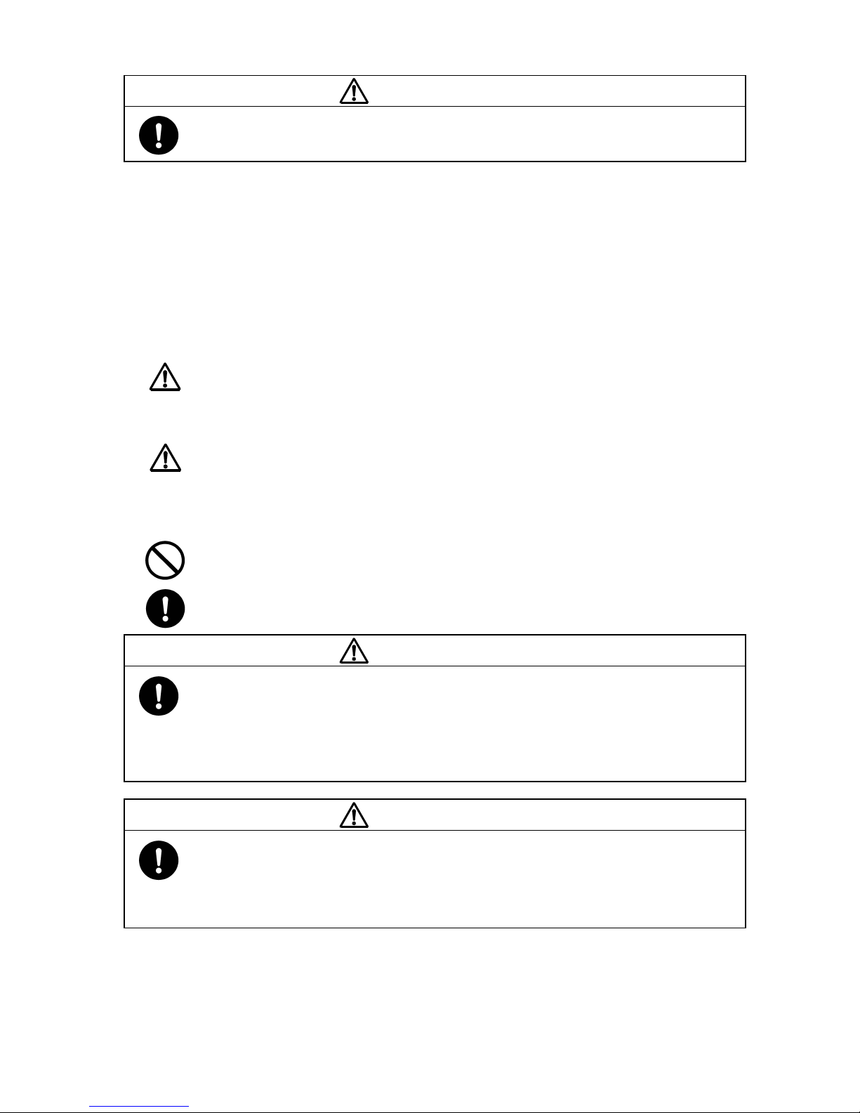
1.Principles of operation
There are two diaphragms fixed to the center rod, one at each end. When compressed air is supplied to air
chamber b (right side, see Fig.1.1), the center rod moves to the right, the material in material chamber B
is pushed out, and at the same time material is sucked into material chamber A.
When the center rod is moved full-stroke to the right, the air switch valve is switched, compressed air is
sent to air chamber a (left side, see Fig.1.2), and the center rod moves to the left. The material in
material chamber A is pushed out, and at the same time material is sucked into material chamber B.
Through repetition of this operation, material is repeatedly taken in and discharged out.
2.Tools, etc.
2.1 General tools
·Socket wrenches 13mm, 17mm, 19mm (except with the NDP-H40 BP□)
24mm (BA
□, BS□, BF□)
·Hexagonal box wrenches 5mm, 6mm
·Small crowbars 2 (B
□C, B□N, B□E, B□V)
·Open-end wrenches 17mm (NDP-H40 BP
□), 19mm (BA□, BS□, BF□)
24mm (BA□, BS□, BF□)
·Phillips-head screw driver
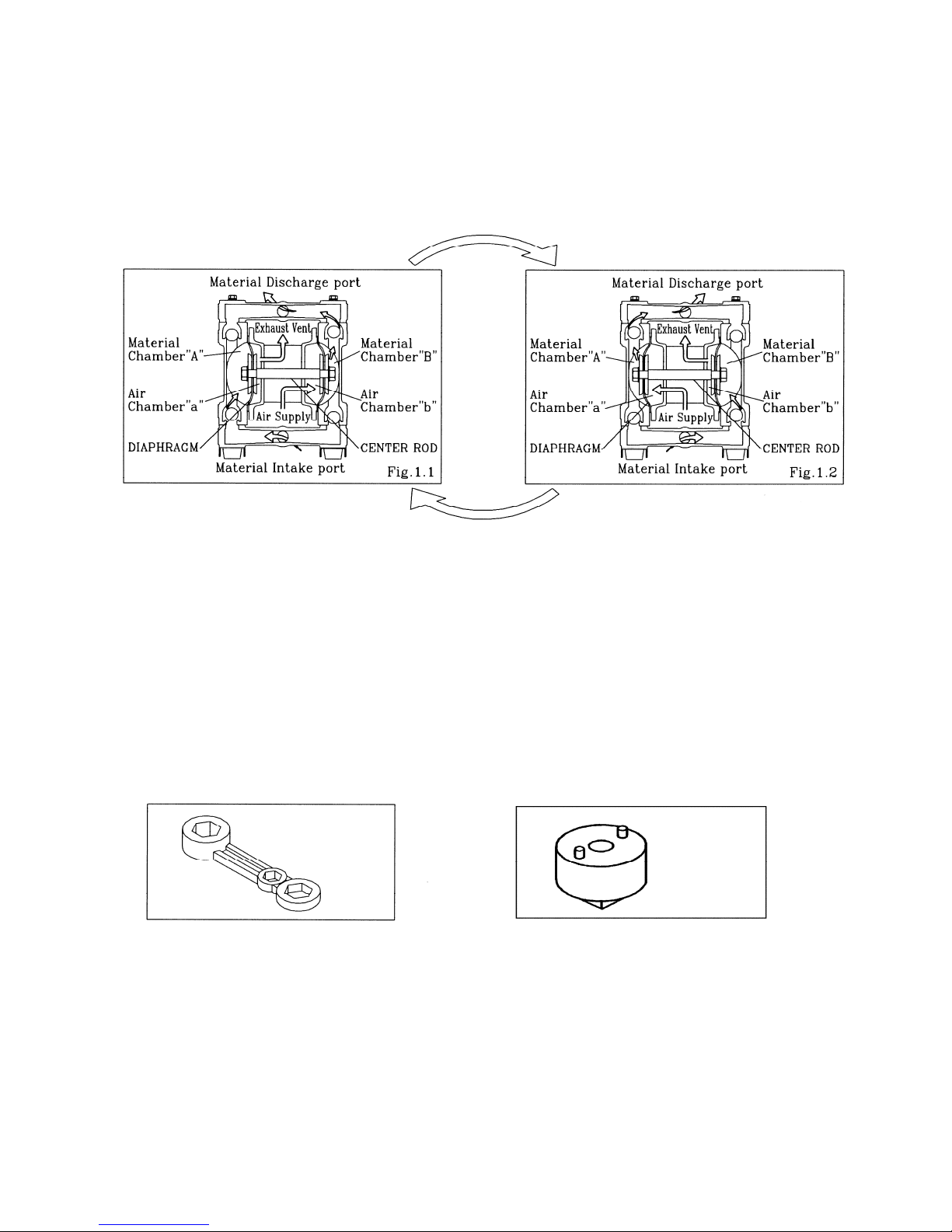
2.2 Special tools
·PP wrench (sold separately) · Socket for a guide (sold separately)
Purpose: Removing the center disk
Purpose: Removing the throat bearing
of BP
□ type
2.3 Misc.
·Assembly oil Turbine oil none addition class 1 (equivalent to ISO VG32 grade)
·Nuts
M16 X 1.5
·Thread locker
·Grease
Urea grease grade (NLGI) No. 2
Shell Alvania Grease S1
3.Ordering Replacement parts
For accurate and speedy shipment of parts, be sure to order the right parts for your model to distributor.
Indicate the part numbers, descriptions, and quantities.
2
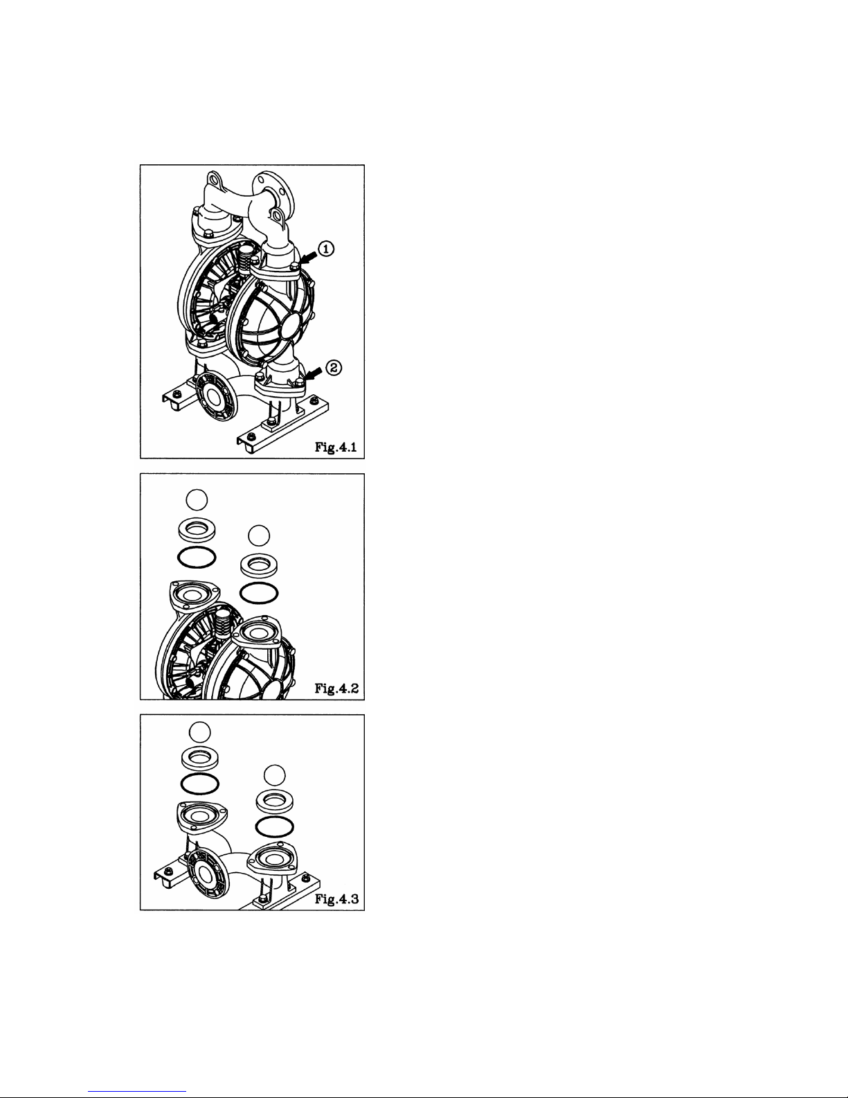
4.Balls and Valve seats
4.1 Removal
■BA□, BS□, BF□ types
▪ Remove the 6 (8 on the NDP-H80) retainer bolts 1
from
the out manifold, and remove the out manifold. [Fig.4.1]
▪ Remove the ball, valve seat and O ring. [Fig.4.2]
▪ Remove the 6 (8 on the NDP-H80) retainer bolts 2 from
the in manifold, and remove the in manifold. [Fig.4.1]
▪ Remove the ball, valve seat and O ring. [Fig.4.3]
3
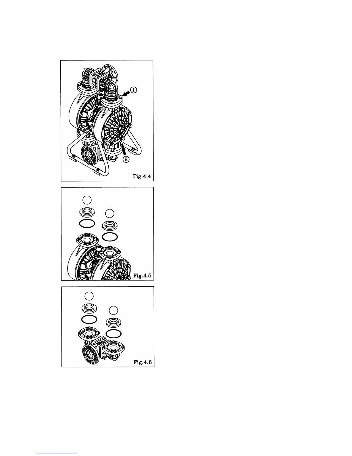
■NDP-H40 BP□ type
▪ Remove the 8 retainer bolts 1 from the out manifold, and
remove the out manifold. [Fig.4.4]
▪ Remove the ball, valve seat and O ring. [Fig.4.5]
▪ Remove the 8 retainer bolts 2 from the in manifold, and
remove the in manifold. [Fig.4.4]
▪ Remove the ball, valve seat and O ring. [Fig.4.6]
 Loading...