

Page 1
Doc. No. APP 079U-03
INSTRUCTION
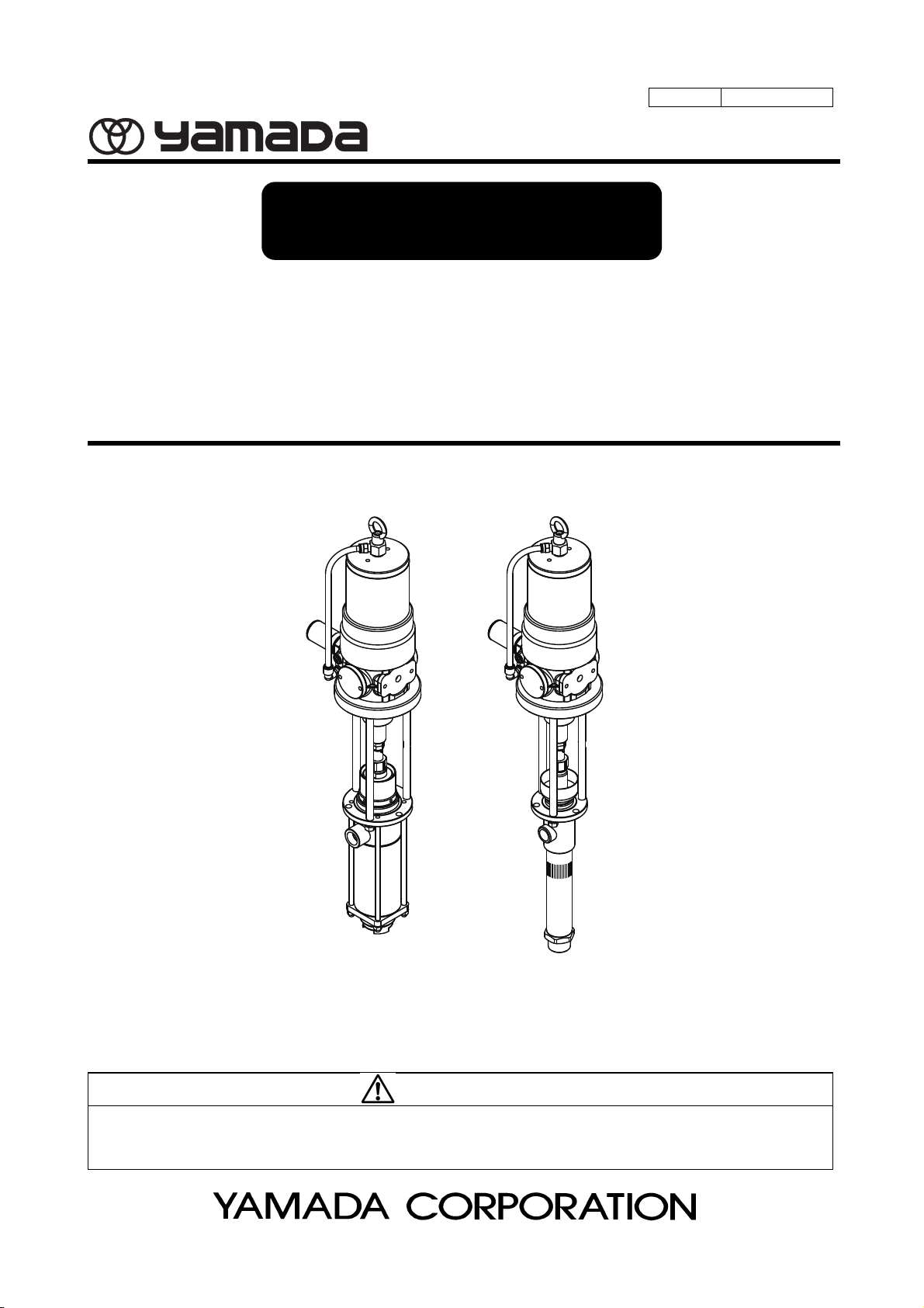
Pump 125 separate type series
SH-125B□ MODEL No.854592・854594・854596 (SIPHON TYPE)
DR-125B
SH-125B
DR-125B
□ MODEL No.854593・854595・854597 (DRUM TYPE)
□-V MODEL No.854598・854600・854602 (SIPHON TYPE -V)
□-V MODEL No.854599・854601・854603 (DRUM TYPE -V)
WARNING
Prior to operating this pump, be sure to read this operation manual for safety. After reading the manual,
please keep it at hand any time for your quick reference.
Page 2
- Preface
Thank you very much for purchasing Yamada Pump. This pump, driven by the compressed air from an air compressor, is
designed to pump out or transfer lubricant from drum cans or other vessels.
125 series pumps are powered by compressed air and designed to transfer low viscosity material such as oil from a drum or
other containers.
For transferring solvent (paint, lacquer, thinner etc.), “-V” type pumps in 125 series are available.
- For Safe Operation
This document describes the items that are important for the user to operate this product safety, correctly, and efficiently.
Before operating this product, read this manual thoroughly, in particular, “Warnings and Cautions” at the beginning of this
manual, with a good understanding of its contents. Keep this manual carefully in an easy-to-access place so that the user
may refer to it whenever necessary.
- Warnings and Cautions
For safe use of this product, be sure to note the following: In this document, warnings and cautions are indicated by symbols.
These symbols are for those who will operate this product and for those who will be nearby, for safe operation and for
prevention of personal injury and property damage. The following warning and caution symbols have the meanings
described below. Be sure to remember their meanings.
WARNING :
This indicates the existence of potential hazard which, if not avoided, will result in
death or serious injury.
1/4
CAUTION :
Furthermore, to indicate the type of danger and damage, the following symbols are also used along with those mentioned
above:
This symbol indicates an act that is prohibited (prohibition). The concrete contents of prohibition are indicated
by the side of the indication.
This symbol indicates the contents that must be observed. The concrete contents of observance are indicated
by the side of the indication.
This indicates the existence of potential hazard which, if not avoided, may result in
bodily injury or in physical damage.
Page 3

- Precautions on Use
The following warnings and cautions are very important. Be sure to observe them.
WARNING
[Operating condition]
- Restriction on handling
Never let anyone operate this unit without understanding this manual.
- Read this manual thoroughly before use.
For your safety, read and understand all information provided in this manual.
If you have lost or damaged your instruction manual, please contact us or our distributor to place an order.
[Operating method]
- Keep your face away from the exhaust and discharge ports.
Material may suddenly come out. There is a possibility of losing eyesight if it strikes eyes.
- Connecting ports
Keep your fingers away from each port to avoid injury from moving parts.
- Understand this manual completely before operating the machine.
The operator and maintenance engineer should read the operation manual thoroughly before operating the
pump and performing maintenance in respect of this pump.
2/4
- Do not use inappropriately.
Use of the product for any purpose other than those specified in this manual may result in personal injury or
property damage.
Be sure to use the unit in accordance with the specifications in this manual.
- Wear proper safety equipments.
Always wear proper safety equipments (facemask, ear plugs, and safety shoes, etc.) when installing,
operating, and disassembling the pump.
- Ground connection
Make ground connection to pump and peripheral equipment. Rapid pumping of material can result in static
electrical charge. Also, be sure to provide proper ventilation where a flammable atmosphere may exist.
- In case of abnormality
If there is any danger or abnormality, discontinue pump operation and refer to Troubleshooting to solve the
problem.
- Do not run the pump dry.
Stop pump operation immediately when a drum becomes empty. Running the pump dry will cause excessiv
Be especially careful when pumping explosive material. Mixture of an air and vaporized material can
explode. If there is any possibility of running dry, install a dry-run protection device like a liquid level control.e
vibration, resulting in reduction of pump life and damage to other equipment.
[Installation and piping]
- Air supply pipe
Attach a valve (for stop in emergency) or regulator to the air supply pipe to keep supply air pressure under
0.7MPa.
- Check strength of mounting surface.
(SH type only) If using a wall mount bracket for installation, the must be strong enough to withstand vibration
of the pump.
[Disassembly, maintenance and inspection]
- No alternation is permitted.
Alternating the unit may result in personal injury or product malfunction. Please do not try to alter, modify, or
change the machine.
- Never use gasoline or any other volatile material.
Gasoline is a high volatile fuel. Never use for cleaning of the unit in any case. Risk of fire or explosion may
exist.
Page 4
- Some materials can be detrimental to the environment.
- Daily checkup
- Shut off air supply.
- Replacement time for consumables
[Installation and piping]
- Install an emergency stop valve.
3/4
WARNING
Do not discharge material directly onto the ground. Dispose of harmful materials according to the
requirements specified in SDS or local regulations. Also, dispose of pump according to the local regulations
after removing residual material from inside pump. (Please contact industrial waste disposal service.)
Execute the daily checkup.
Before maintenance involving disassembly, be sure to shut off air supply to the pump and release residual air
pressure and material pressure in the tubes and pump. Failure to do so may result in material gushing out.
The life of consumables varies depending on operating conditions. Replace a degraded part with a new one.
CAUTION
Attach an emergency stop valve to the air piping (somewhere accessible between the air source and unit)
and close this valve in case of emergency.
- Stop operation.
If any abnormality is found during operation, immediately stop the machine. Do not restart until the cause has
been identified and corrected.
- Shut off air supply.
Shut off the air source before installation and piping.
- Install properly.
Install the unit properly according to the requirements for location and material, pressure resistance, and size
of hoses and other device, avoiding lift operation failure and pipe leakage or breakage.
- Measures against rainwater and dust
Take protective measures against rainwater and dust. It is likely to lead to the pollution of the material.
- When installing the pump
Be very careful about your posture when installing the pump. Back injury may be caused by lifting the pump.
Be very careful about the edge of the pump when you lift the pump. Your hands might be injured.
- When installing the drum
(DR type only) Place a drum on a flat, level surface to position pump horizontally against a ground. Operating
the pump on a slope may cause a fall or tip-over due to shift in center of gravity caused by change in the
material level.
- Do not plumb directly.
Do not connect the material outlet and piping directly. Attach a flexible tube like a hose to connect the pump
to the piping. The pump, if connected directly to the piping, may cause many problems (e.g., noise caused by
vibration, damage to the piping, operation failure of the lift, and failure of maintenance).
Page 5
4/4
CAUTION
[Handling]
- Keep hands and fingers away from the pump during operation.
Keep hands and fingers away from the pump during operation to avoid injury from moving parts.
Do not touch the surfaces of the pump and the hose when pumping high-temperature material. Risk of burns
exists.
- In case of emergency
In case of emergency, close emergency stop valve
- Maximum operating pressure of the pump
Do not exceed the maximum operating pressure of the pump (0.7MPa).
- Material
Use pump for the material suitable for the specification. Parts may be corroded and material leak from the
damaged parts can lead to environmental pollution. Also, follow handling notes (SDS) of the manufacturer
about the handling of the material used.
- Fall-prevention measures
Take fall-prevention measures if using a slim or light tank. Risk of falling will be increased due to shift in
center of gravity caused by change in the material level in a tank.
When using a bung adapter, to prevent the pump from falling over, hang the pump with a crane etc.
- When Replacing drum
[Shutdown and storage]
- When left unused for a long time (an week or more) or shutdown
(DR type only) Material remaining inside or on the surface of the pump may spill out by inserting or removing
the pump into from a drum. Be very careful not to get your clothing dirty.
Shut off air source after work and nighttime, holidays, or when the pump is not in use for a while. Also, open
the valve at the discharge port to release residual pressure in the pump and hoses. Failure to do so may
result in damage to the hoses or facility pollution due to leak from the valve. The use has a responsibility for
such secondary accidents.
Page 6

Table of Contents
- Preface
- For Safe Operation
- Warnings and Cautions
- Precautions on Use
- Table of Contents
1. Part Names
1.1 Part names ······························································································ 1
1.2 Contents of a package ···························································································· 1
2. Operating principle ···················································································· 1
3. Preparation of Installation and Operation ························································
3.1 Pump installation ··································································································· 3
3.2 Installation of drum pump(Using a drum cover) ···························································· 3
3.3 Installation of drum pump(Using a bung adapter) ·················································· 3
3.4 Installation of siphon pump ······················································································ 4
3.5 Installation of silencer ····························································································· 4
3.6 Connecting the ground wire ····················································································· 4
3.7 Discharge piping ··································································································· 5
3.8 Air piping ············································································································· 5
3.9 Preparation for use ································································································ 5
4. Operating Method ······················································································ 6
4.1 Operation switch and valve ······················································································ 7
4.2 Solvent cup ·········································································································· 7
4.3 Filling delivery piping with material ············································································ 8
4.4 Operation ············································································································ 8
4.5 Retightening gland packing ····················································································· 8
4.6 When container is empty (changing drum) ·································································· 8
4.7 After work ············································································································ 8
5. Maintenance and Inspection ········································································ 9
5.1 Maintenance and Inspection ···················································································· 10
5.2 Troubleshooting ···································································································· 11
5.3 Consumable
5.4 Design standard use period ··········································································· 13
6. Parts Disassembly Drawing and Parts List ······················································ 13
7. Specifications ···························································································
8. Limited Warranty ······················································································· 22
····························································································· 12
2
19
Page 7
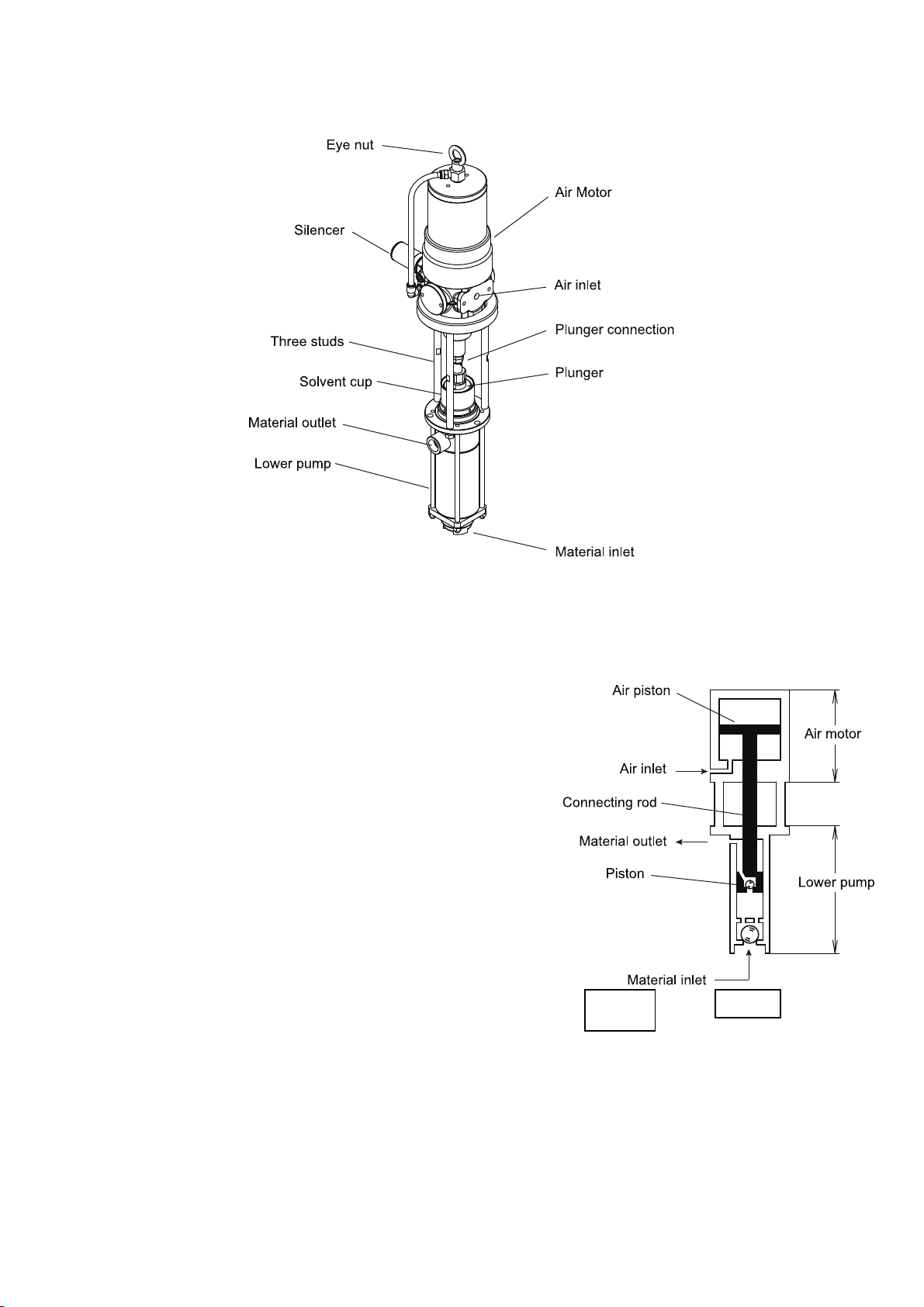
1. Part Names
1.1 Part names
1.2 Contents of a package
Fig. 1 Part names
Unpack and check the pump for any damage.
2. Operating Principle
Yamada's air-powered pumps employ reciprocating motion system
driven by compressed air.
It is comprised of two sections as illustrated at right; air motor section
which drives the pump and lower pump section which pump up
material.
When compressed air, generated by the compressor, is fed into the
air motor, the air switching mechanism built in the air piston actuates
vertical reciprocating motions. The connecting rod, joining the air
piston inside the air motor and the piston inside the lower pump,
transmits the movement to the piston inside the lower pump, giving
vertical reciprocating strokes.
Vertical reciprocating motions, generated by the lower pumps, feed
material into the lower pump. Then, it is pumped out of the discharge
port.
Fig. 2
1
Page 8
3. Preparation of Installation and Operation
WARNING
- Keep your fingers away from each port to avoid injury from moving parts
- The pump weighs about 30kg. Be careful not to let the pump fall over or get crushing injury during
installation.
- Always wear proper safety equipments (facemask, ear plugs, and safety shoes, etc.) when installing,
operating, and disassembling the pump.
- Make ground connection when working with flammable material or in explosive atmosphere. Rapid
pumping of material can result in static electrical charge. Also, be sure to provide proper ventilation
where a flammable atmosphere may exist.
- Attach a valve (for stop in emergency) or regulator to the air supply pipe to keep supply air pressure
under 0.7MPa.
- (SH type only) If using a wall mount bracket for installation, the wall must be strong enough to
withstand vibration of the pump.
CAUTION
- Keep hands and fingers away from the pump during operation to avoid injury from moving parts.
Do not touch the surfaces of the pump and the hose when pumping high-temperature material. Risk of
burns exists.
- Attach an emergency stop valve to the air pipe (somewhere accessible between the air source and
unit), and in case of emergency, close this valve.
- If there is any danger or abnormality, discontinue pump operation and refer to Troubleshooting to solve
the problem.
- Shut off the air source before installation and piping.
- When installing the pump, select an appropriate place and suitable piping material, pressure
resistance, and size to avoid leakage and damage to the piping.
- Take protective measures against rainwater and dust. It is likely to lead to the pollution of the material.
- Be very careful about your posture when installing the pump. Back injury may be caused by lifting the
pump.
- Be very careful about the edge of the pump when you lift the pump. Your hands might be injured.
- (DR type only) Place a drum on a flat, level surface to position pump horizontally against a ground.
Operating the pump on a slope may cause a fall or tip-over due to shift in center of gravity caused by
change in the material level.
- Do not directly connect the piping to the pump. Be sure to use a flexible tube like a hose to connect
between the pump and piping. Direct connection damages the piping by vibrations when running the
pump, causes noises, and in case of the drum pump, makes it impossible to replace the drum can and
disables maintenance of the pump.
- Take fall-prevention measures if using a slim or light tank. Risk of falling will be increased due to shift in
center of gravity caused by change in the material level in a tank.
- When using a bung adapter, to prevent the pump from falling over, hang the pump with a crane etc.
2
Page 9
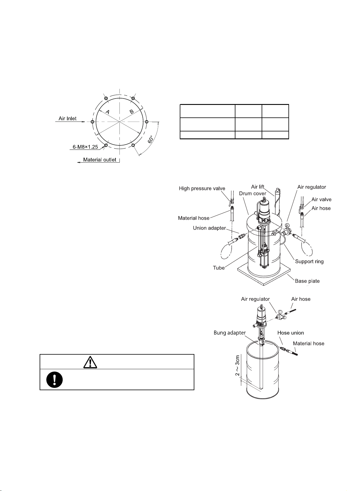
3.1 Pump installation
Refer to Fig. 3 for mounting dimensions of the pump. Make sure the environment to install the pump satisfies the
following conditions:
- A flat surface indoor (area where exhaust from the pump does not affect peripheral equipment)
- Enough space to perform maintenance
Fig. 3 Pump mounting dimension
3.2 Installation of drum pump
(Using a drum cover: DR-125B3.5, DR-125B5)
1) Secure the pump to a drum cover (sold
separately) and mount it on an open top drum.
2) When installing on a drum, use a crane to lift up
the pump with the eye nut on the top.
3.3 Installation of drum pump
(Using a bung adapter: DR-125B13)
1) Remove a plug on a drum and attach a bung adapter (sold
separately).
2) Insert the pump into the bung adapter. Once the lower end
(foot valve) reaches the bottom of the drum, lift up the
pump 2-3 cm above to make space between the foot valve
and the bottom of the drum. Then, secure a wing screw on
the bung adapter to set the pump in place.
When installing on a drum, use a crane to lift up the pump with
the eye nut on the top.
To prevent the pump from falling over, keep hanging the pump
with a crane.
3.5×1
5×1
A : Dimension of
mounting plate
B : Bolt hole P.C.D.168 P.C.D.140
Fig. 4
φ152 φ122
13×1
CAUTION
- When using a closed type drum, loosen a vent plug
to avoid creating a vacuum.
3
Fig. 5
Page 10

3.4 Installation of siphon pump
(Using a wall bracket)
1) Attach a wall bracket (sold separately) or a panel
unit (sold separately) to the pump. Or secure the
pump to a mounting.
2) Connect a suction hose assembly (sold
separately) to the pump.(Fig. 6)
3.5 Installation of silencer
CAUTION
- Each connection is capped. Remove the caps all.
Fig. 6
- Wrap sealing tape around the silencer thread to prevent leakage.
Attach the silencer to the pump and secure it using a tool. (Fig. 7)
Wrap sealing tape around the silencer thread to prevent leakage.
3.6 Connecting the ground wire
WARNING
- Make ground connection when working with flammable material or in explosive atmosphere. Rapid
pumping of material can result in static electrical charge. Also, be sure to provide proper ventilation
where a flammable atmosphere may exist.
1) When installing the pump, be sure to connect the ground wire at the
specified position. For the specified position for connecting the ground
wire, see [1. Names of parts and materials].(Fig. 8)
2) Also connect ground wires to peripheral equipment and piping.
3) Use 2.0mm
2
minimum ground wire.
Fig. 7
Fig. 8 Position for connecting
the ground wire
4
Page 11

3.7 Discharge piping
1) Connect a discharge hose to the pump outlet. Make sure the hose satisfies the following requirements:
- Resistant to material being pumped and unaffected by environment
- Satisfying the following normal operation pressure:
- 3.5×1 ratio pump : 2.45MPa or more
- 5×1 ratio pump : 3.5MPa or more
- 13×1 ratio pump : 9.1MPa or more
- A flexible hose with an adequate length in order not to be affected by replacing a material container
- When mounting the pump on an elevating machine like a lift, be sure to use a flexible hose with an adequate
length in order not to be affected by up-and-down movement.
- Recommended size: 1 inch or 3/4 inch or more
- Hose fitting or joint: Connectable to Rc1 or Rc3/4 material outlet
- A relief valve (required)
2) Connect the other end of the hose to a delivery pipeline or oil gun (sold separately). Attach a valve at the
connection between the hose and the piping for maintenance and keep it closed until unit installation is
completed.
3.8 Air piping
1) Connect air piping equipment such as an air valve and air regulator to the air inlet of the pump. Attach an
emergency stop valve to the air pipe (somewhere accessible between the air source and unit).
2) Select an air supply hose, fitting, and air equipment that satisfy the following requirements. With these devices,
connect an air piping and the air inlet. Be careful not to let the hose get caught on peripheral equipment.
- Designed for use with air and unaffected by environment
- Normal operation pressure: 0.7MPa or more
- Recommended size: 3/8 inch or more
- A flexible hose
- Comfortable hose length for up/down movement of the lift
- Hose fitting or joint: Connectable to Rc3/8 air inlet
- Flow rate: 1300L/min (ANR) or more
NOTE
The air regulator controls supply air pressure to the pump. Accordingly, the pump operates efficiently without
unnecessary movement and thus the life of the pump can be extended.
3.9 Preparation for use
WARNING
- Gasoline is a high volatile fuel. Do not use it to clean the pump in any case, otherwise ignition or
explosion may be caused.
CAUTION
- Following materials are used for packings and O-rings. Please do not use solvent that corrode these
when washing pump.
- 3.5x1 and 5x1 pump except “-V” series … NBR, PTFE
- 3.5x1 and 5x1 pump “-V” series …………. FKM, PTFE
- 13x1 pump except “-V” series ……………. NBR, Leather
- 13x1 pump “-V” series …………………….. NBR, Leather
The pump has been tested using mineral oil before delivery. Please wash inside the pump with appropriate solvent for
the material being pumped.
5
Page 12

4. Operating Method
- Keep your face away from the exhaust and discharge ports. Material may suddenly come out. There is
a possibility of losing eyesight if it strikes eyes.
- Keep your fingers away from each port to avoid injury from moving parts.
- Do not discharge material directly onto the ground. Dispose of harmful materials according to the
requirements specified in SDS or local regulations. Also, dispose of pump according to the local
regulations after removing residual material from inside pump. (Please contact industrial waste
disposal service.)
- The operator and maintenance engineer should read the operation manual thoroughly before operating
the pump and performing maintenance in respect of this pump.
- Use of the product for any purpose other than those specified in this manual may result in personal
injury or property damage.
Be sure to use the unit in accordance with the specifications in this manual.
- Always wear proper safety equipments (facemask, ear plugs, and safety shoes, etc.) when installing,
operating, and disassembling the pump.
- Make ground connection when working with flammable material or in explosive atmosphere. Rapid
pumping of material can result in static electrical charge. Also, be sure to provide proper ventilation
where a flammable atmosphere may exist.
WARNING
- If there is any danger or abnormality, discontinue pump operation and refer to Troubleshooting to solve
the problem.
- Stop pump operation immediately when material in a container is all gone. Running the pump dry will
cause excessive vibration, resulting in reduction of pump life and damage to other equipment.
Be especially careful when pumping explosive material. Mixture of an air and vaporized material can
explode. If there is any possibility of running dry, install a dry-run protection device like a liquid level
control.
6
Page 13

CAUTION
- Do not exceed the maximum operating pressure of the pump (0.7MPa). Overpressure may cause a
product failure resulting in serious personal injury and/or property damage.
- In case of a pump malfunction or shutdown, refer to “5.2 Troubleshooting” to judge the situation
thoroughly and disassemble the pump only as necessary.
- Keep your hand away from the three studs connecting the air motor and lower pump. Fingers can get
caught in the reciprocating plunger.
In case of transferring high-temperature material, surface of pump and piping may be hot as well. It
may cause of burn. Please do not touch them.
- In case of emergency or abnormality, close emergency stop valve.
- Please do not operate pump when supplying solvent to the solvent cup and retightening gland packing.
- In case of following condition, please do not put your face in the material discharge port. There is a risk
of splashing liquid with compressed air
- When removing air from lower pump.
- Right after replacing material container.
- Use this product for the material suitable for the specification. Parts may be corroded and material leak
from the damaged parts can lead to environmental pollution. Also, follow handling notes (SDS) of the
manufacturer about the handling of the material used.
- Take fall-prevention measures if using a slim or light tank. Risk of falling will be increased due to shift in
center of gravity caused by change in the material level in a tank.
When using a bung adapter, to prevent the pump from falling over, hang the pump with a crane etc or
fix container firmly.
- (DR type only) Material remaining inside or on the surface of the pump may spill out by inserting or
removing the pump into from a drum. Be very careful not to get your clothing dirty.
- Shut off air source after work and nighttime, holidays, or when the pump is not in use for a while. Also,
open the valve at the discharge port to release residual pressure in the pump and hoses. Failure to do
so may result in damage to the hoses or facility pollution due to leak from the valve. The use has a
responsibility for such secondary accidents.
4.1 Operation switch and valve
- Pump Air Regulator (sold separately)
Function : Controlling air pressure for pump operation.
To operate : Clockwise turn will increase pressure. Counterclockwise turn will decrease pressure.
(It can be locked by pushing the knob in.)
Note : The maximum allowable operating pressure of the pump is 0.7MPa. DO not exceed this limit.
Remark : Discharge pressure can be calculated by multiplying the air pressure by the pump ratio.
- Air Valve, Pump (sold separately)
Function : Starting/Stopping the pump.
To operate : When the lever is parallel to the pipe, the valve is open. If the lever is perpendicular to the pipe,
the valve is closed.
In case of emergency, close this valve.
4.2 Solvent cup
(This procedure is not necessary if lower pump has a soak in drum, such as using with drum cover)
1) The pump is equipped with a solvent cup to keep the packing from sticking to the plunger. Shut down the pump
and then fill the cup 2/3 full with suitable lubricant or solvent.
2) When lubricant in the cup runs out during operation, shut down the pump first and refill the cup.
7
Page 14

4.3 Filling delivery piping with material
1) Open valve for material discharge.
2) Open the air valve for the pump and increase air pressure gradually with the pump air regulator. The pump will
start operating at approx. 0.05MPa. Adjust the pump air regulator to set pump speed to 5-8 seconds per cycle.
3) Air-containing material will be discharged from the material discharge port. Put a plastic bag over the port to
receive discharged material. Keep the pump operating until the air inside material is released completely. Then
close the material discharge valve by securely tightening it.
4) After filling delivery piping with material, close the air valve for the pump and set the pump air regulator to 0MPa.
4.4 Operation
1) Adjust the pump air regulator to set to the desirable operating pressure. An estimate of the material discharge
pressure to the supply air pressure is calculated by “supply air pressure × pump ratio”.
(e.g. When operating a 13:1 ratio pump at 0.7MPa supply air pressure, material will be discharged at approx.
9.1MPa.)
2) Open discharge valve and the pump will automatically start to operate and discharge the material. When the
valve is closed, the pump is automatically stopped.
NOTE
Material viscosity varies with changes in temperature. It is recommended to make a note of appropriate pressure
for each season.
4.5 Retightening gland packing (“-V” series)
Because of the deformation or wear of gland packing, solvent cup of “-V” series loose the tightness. In order to
protect plunger and packing, and to prevent leak, please tighten it on a regular basis. Please do it when the
pump is stopped.
NOTE
After retightening, verify that the pump runs at 0.05MPa without leakage from the gland part.
.
4.6 When container is empty (changing drum)
1) When the container such as drum is empty, the pump continued to operate without stop automatically. Please
close the air valve as soon as possible. Then please set air regulator to 0MPa.
2) <Used with drum cover>
Lift up the pump and drum cover by crane and replace to new container such as drum.
<Used with bung adapter>
Loosen wing bolt of the bung adapter. Lift up the pump by crane and remove from drum. When new drum is
ready, follow “3.3 Installation of Drum Pump (Using a bung adapter: DR-125B13)”.
<Siphon pump used with suction tube>
Remove the suction tube from container, and set to new container.
3) When changing container, air will contaminate in the pump. Be careful of air-containing material discharged
from the material discharge port when restart the pump.
To remove air, please follow chapter 3) of “4.3 Filling delivery piping with material”.
4.7 After work
1) Close the air valve for the pump and set the pump air regulator to 0MPa.
2) Open the valve on the discharge port to release residual pressure on air and material inside the pump and
piping.
8
Page 15

5. Maintenance and Inspection
- Keep your face away from the exhaust and discharge ports. Material may suddenly come out. There is
a possibility of losing eyesight if it strikes eyes.
- Keep your fingers away from each port to avoid injury from moving parts.
- Modification of this pump may lead to death, bodily injury, or a failure. Do not modify it in any case
because it involves a risk.
- Gasoline is a high volatile fuel. Do not use it to clean the pump in any case, otherwise ignition or
explosion may be caused.
- Do not discharge material directly onto the ground. Dispose of harmful materials according to the
requirements specified in SDS or local regulations. Also, dispose of pump according to the local
regulations after removing residual material from inside pump. (Please contact industrial waste
disposal service.)
- Always wear proper safety equipments(facemask, ear plugs, and safety shoes, etc.) when installing,
operating, and disassembling the pump.
- Stop pump operation immediately when a drum becomes empty. Running the pump dry will cause
excessive. Be especially careful when pumping explosive material. Mixture of an air and vaporized
material can explode. If there is any possibility of running dry, install a dry-run protection device like a
liquid level control.e vibration, resulting in reduction of pump life and damage to other equipment.
CAUTION
- Execute the daily checkup.
- Before maintenance involving disassembly, be sure to shut off air supply to the pump and release
residual air pressure and material pressure in the tubes and pump. Failure to do so may result in
material gushing out.
- The life of consumables varies depending on operating conditions. Replace a degraded part with a new
one.
CAUTION
- When performing maintenance or inspection, notify workers by hanging a sign or other method to keep
them from touching the unit.
- If there is any danger or abnormality, discontinue pump operation and refer to Troubleshooting to solve
the problem.
- Be sure to shut off air supply to the pump before maintenance and inspection.
- When performing maintenance and inspection, please be careful of edge of pump. It may cause of
personal injury.
9
Page 16

5.1 Maintenance and inspection
INTERVAL ACTION
Daily 1)Inspect operation of pump.
Weekly 2)Lubricate pump. (turbine oil, class#1, additive-free: ISO V 32)
Annually 3)Check for loose bolts and nuts.
Triennially 4)Overhaul pump.
1) Inspect operation of pump
Inspect pump to ensure the following:
- The pump operates normally and smoothly,
- There is no air/material leak in each part of the pump or air/material piping,
- There is no abnormal noise during pump operation, and
- There is no abrasion or deterioration apparently in each part of the pump.
2) Lubricate pump
Lubricate pump according to the following procedure:
- Close the air valve for the pump and set the pump air regulator knob to 0MPa.
(Without a lubricator)
- Disconnect the air piping from the air inlet of the pump and apply a few drops (approx. 0.5mL) of lubricant
directly to the pump.
(With a lubricator)
- Check the amount of oil remaining in the lubricator and fill it with lubricant if needed.
3) Check for loose bolts and nuts
Check bolts and nuts according to the following procedures:
- Completely shut down the pump and lift by disconnecting from the air source, for example.
- Ensure that all visible bolts and nuts on the pump and lift cannot be loosened by hand.
4) Overhaul pump
Pump needs to be overhauled triennially. Please contact the retail store where you purchased your pump or our
business office for overhaul. Earlier overhaul is recommended depending on use frequency and deterioration
degree.
10
Page 17

5.2 Troubleshooting
If you suspect that you have a problem with your product, consult the table below for some common problems and
their solutions. Contact the retail store where you purchased your product or our business office if all else fails.
PROBLEM POSSIBLE CAUSE REMEDY
Com press or is off. Turn on com pressor.
Valve on air piping is closed. Open valve.
Air press ure setting is under 0.2MPa. Set air pressure to 0.2MPa or above.
Valve on material outlet is closed. Open valve.
Frost occurs inside silencer. Us e dry air.
Pump doesn’t run
Air leak from air
motor
Air leak from
silencer during
shutdown
O ring on sliding part of air piston is worn out.
(Air leak occurs from silencer.)
Block (773210) and ball (686271) in valve body (804815) are
worn out.
Any parts (e.g. spring, pin) used in switching system in valve
body (804815) or air motor (804814 / 804856) are damaged.
- Fasteners are loose.
- O rings and packings are worn out.
- Foreign object is caught between block (773210) and
valve s eat (716246) in valve body (804815).
- Seating part is worn out.
Replace worn out or damaged part.
- Retighten loose parts.
- Replace worn part.
- Remove foreign object.
- Replace worn part.
Pump doesn’t run
and air leaks from
silencer
Pump doesn’t draw
mate ri al at firs t tim e
of operation
Material cannot be
pumped out
Pump doesn’t stop
Material leak from
lower pump
Material contains
air bubbles even
after bleeding
- Foreign object is caught between spindle (716299) and
valve s witcher (832996) in air motor (804814 / 804856).
- There exists damage that prevents sliding movement of
parts below.
Pump operating speed is so fast that lower pump s uction
cannot keep up with pump movement. (Valve inside lower pump
is not working well.)
If upward movement of plunger is faster,
- seat surface of piston valve is defective (wear of seat
surface, inclusion of foreign material) or,
- packings are damaged.
If downward movement of plunger is faster,
- seat surface of foot valve is defective (wear of seat
surface, inclusion of foreign material),
- packings are damaged, or
- shovel rod is bent.
If downward movement of plunger is faster, operating speed is
so fast that lower
pump suction cannot keep up with pump movement. (Vacuum
is caused ins ide lower pump.)
Connecting rod connecting air motor and lower pump is
com pletely se parated from air m o tor. (In thi s cas e, parts i ns ide
of lower pump may be damaged.)
Leak occurs in delivery pipe.
Leak occurs in lower pump (connections are loosened or o ring,
backup ring, or packing is damaged).
- Fasteners are loose.
- O ring, backup ring or packing is damaged.
- Fasteners are loosened.
- O ring or backup ring is damaged.
- Remove foreign object.
- Replace damaged part.
Set pump speed to 5-8 sec. per cycle
until material is pumped out.
- Remove foreign object.
- Replace damaged part.
Decrease air press ure until material
comes out. (This pressure is the upper
limit of normal operating pressure.)
Ins p ect ins ide lo wer pum p firs t, then
replace damaged part, and retighten
each part.
- Retighten loose parts.
- Replace damaged part.
- Retighten loosened parts.
- Replace damaged part.
- Retighten loosened parts.
- Replace damaged part.
11
Page 18

5.3 Consumables
Refer to chart under for replacement time for consumables used in the pump. The replacement time should be used
only as a guide. Consumption varies depending on use conditions. Also, be sure to replace a part when you find any
defect like a leak during operation.
■ Air Motor Assembly
<804855> <804856>
SH-125B3.5) (SH-125B3.5-V) (SH-125B5) (SH-125B5-V)
(
(DR-125B3.5) (DR-125B3.5-V) (DR-125B5) (DR-125B5-V)
<804857> <804861> <804858> <804862>
Part No.
640033
640072
640034
570145
<804815>
716246
773210
706612
686271
Description Q'ty Times of replacement
Air m otor assem bly
O ring 1 per unit 5 million cycles
O ring 1 per unit 5 million cycles
O ring 1 per unit 5 million cycles
Tube 1 per unit 6 years
Val ve Bo dy As s e m b ly
Valve seat 1 per unit 10 million cycles
Block 1 per unit 10 million cycles
Spring 1 per unit 10 million cycles
Ball 1 per unit 10 million cycles
■ Lower Pump Assembly
Part No.(Type)
854592 854598 854594 854600
Description Q'ty
854593 854599 854595 854601
Lower Pump Assembly
716425 716427
686390 686391 Packing 1 per unit 5 million cycles
770492 770207 V Packing 3 per unit 3 million cycles
701382 701369
630479
701360
770493 770208
630487
833004
Plunger 1 per unit 10 million cycles
Cylinder 1 per unit 10 million cycles
Ball 1 per unit 6 million cycles
Valve Seat 1 per unit 6 million cycles
Packing 2 per unit 3 million cycles
Ball 1 per unit 6 million cycles
Foot Valve 1 per unit 6 million cycles
Tim es of
replacement
Part No.(Type)
854596 854602 854597 854603
(SH-125B13) (SH-125B13-V) (DR-125B13) (DR-125B13-V)
<804859> <804863> <804860> <804864>
716480
685795 685795 Packing 1 per unit 5 million cycles
770062 770062 V Packing 6 per unit 3 million cycles
704583
704580
630334
701553
770233
770151
630341
704586 704587
Description Q'ty
Lower Pump Assembly
Plunger 1 per unit 10 million cycles
Suction Tube 1 per unit 10 million cycles
Cylinder 1 per unit 10 million cycles
Ball 1 per unit 6 million cycles
Valve Seat 1 per unit 6 million cycles
Revolving 1 per unit 3 million cycles
Packing 2 per unit 3 million cycles
Ball 1 per unit 6 million cycles
Foot Valve 1 per unit 6 million cycles
Tim es of
replacement
12
Page 19

y
y
(
)
y
5.4 Design standard use period
Design standard use period is established for the product. (See the table below.)
Use of the product beyond this period may result in personal injury or property damage.
①SH-125B3.5, DR-125B3.5, SH-125B3.5-V, DR-125B3.5-V ·················· 10years
②SH-125B5, DR-125B5, SH-125B5-V, DR-125B5-V ···························· 10 years
③SH-125B13, DR-125B13, SH-125B13-V, DR-125B13-V ····················· 10 years
Standard
Conditions of Use
Application
Season
Temperature
Material being
pumped
Container
air pressure
Suppl
Discharge Volume
Daily Amount of
Material being
Discharge volume
Operating Days per
per C
pumped
ear
cle
①SH/DR-125B3.5□②SH/DR-125B5□③SH/DR-125B13□
Pumping grease
Spring and Fall
20℃
Hydraulic oil
ISO VG32 20℃
Open Head Drum (200L): JIS Z 1601 class 1
0.5 MPa
619 mL / cycle 458 mL / cycle 171 mL / cycle
2000L 1600L 600L
260 days (5 days a week)
Hydraulic oil
ISO VG220 20℃
6. Parts Disassembly Drawing and Parts List
■Pump assembly SH-125B3.5(854592), SH-125B5(854594), SH-125B3.5-V(854598), SH-125B5-V(854600)
No. Description Q'ty
854592 854594 854598 854600
1 804855 Air motor assembly 1
4 632059 Slit pin 1
5 716409 Bushing 1
6 700350 Cap nut 1
7 716410 Stud 3
8 631918 Wave spring washer 3
9 627045 Nut 3
10 804857 804858 804861 804862 Nut 1
14 804697 Silencer 1
Part No.
13
Page 20

■Pump assembly DR-125B3.5(854593), DR-125B5(854595), DR-125B3.5-V(854599), DR-125B5-V(854601)
No.
854593 854595 854599 854601
1 804855 Air motor assembly 1
4 632059 Slit pin 3
5 716409 Bushing 1
6 700350 Cap nut 1
7 716411 Stud 3
8 631918 Wave spring washer 3
9 627045 Nut 3
10 804857 804858 804861 804862 Lower pump assembly 1
12 716288 Joint 1
13 716412 Connecting rod 1
14 804697 Silencer 1
Part No.
■Pump assembly SH-125B13(854596), DR-125B13(854597), SH-125B13-V(854602), DR-125B13-V(854603)
No.
854596 854597 854602 854603
1 804856 Air motor assembly 1
4 632059 Slit pin 1
5 716409 Bushing 1
6 700350 Cap nut 1
7 716410 Stud 3
8 631918 Wave spring washer 3
9 627045 Nut 3
10 804859 804860 804863 804864 Lower pump assembly 1
14 804697 Silencer 1
Part No.
Description Q'ty
Description Q'ty
14
Page 21

■Lower pump assembly 804857, 804858(For SH/DR-125B3.5, For SH/DR-125B5)
No.
10-1 833003 Body as sembly 1
10-2 701360 Valve seat 1
10-3 716423 Rod 4
10-4 631917 Wave spring washer 7
10-5 627013 Nut 4
10-6 701355 Packing gland 1
10-8 640011 O ring 2
10-9 703529 703526 Chamber 1
10-10 640136 640134 O ring 2
10-11 640139 O ring 1
10-12 716424 716429 Throat bearing 1
10-13 686390 686391 Packing 1
10-14 701381 701371 Washer 1
10-15 716413 Stud 1
10-16 716425 716427 Plunger 1
10-17 701382 701369 Cylinder 1
10-18 704742 704744 Chamber 1
10-19 630479 Ball 1
10-21 770493 770208 Packing 2
10-22 701379 701366 Washer 1
10-23 704741 704743 Washer 1
10-24 611175 Bolt 3
10-25 833004 Foot valve 1
10-26 701359 Pin 1
10-27 701388 701362 Washer 1
10-28 630487 Ball 1
10-29 701358 Foot valve body 1
10-30 716428 Ball guide 1
Part No.
804857 804858
Description Q'ty
15
Page 22

■Lower pump assembly
804861, 804862(For SH/DR-125B3.5-V, For SH/DR-125B5-V)
10-1 833003 Body assembly 1
10-2 701360 Valve seat 1
10-3 716423 Rod 4
10-4 631917 Wave spring washer 7
10-5 627013 Nut 4
10-6 701355 Packing gland 1
10-8 642011 O ring 2
10-9 703529 703526 Chamber 1
10-10 642136 642134 O ring 2
10-11 701384 701373 Packing gland 1
10-12 770492 770207 V Packing 3
10-13 701385 701372 Packing gland 1
10-14 701381 701371 Washer 1
10-15 716413 Stud 1
10-16 716425 716427 Plunger 1
10-17 701382 701369 Cylinder 1
10-18 704742 704744 chamber 1
10-19 630479 Ball 1
10-21 770493 770208 Packing 2
10-22 701379 701366 Washer 1
10-23 704741 704743 Washer 1
10-24 611175 Bolt 3
10-25 833004 Foot valve 1
10-26 701359 Pin 1
10-27 701388 701362 Washer 1
10-28 630487 Ball 1
10-29 701358 Foot valve body 1
10-30 716428 Ball guide 1
Part No.
804861 804862
Description Q'tyNo.
16
Page 23

■Lower pump assembly 804859, 804860 (For SH-125B13, For DR-125B13)
No.
Part No.
804859 804860
Description Q'ty
10-2 833014 Solvent cup assembly 1
10-4 716480 Plunger 1
10-6 833005 Body assembly 1
10-7 640133 O ring 1
10-8 716431 Throat bearing 1
10-9 685795 Packing 1
10-10 640135 O ring 1
10-11 701552 716433 Rod 1
10-12 704583 704580 Cylinder(Suction tube) 1
10-13 640012 O ring 1
10-14 632774 Spring pin 1
10-15 627016 Nut 1
10-16 701554 Housing 1
10-17 630334 Ball 1
10-18 701553 Valve seat 1
10-19 770233 Revolving stopper 1
10-20 701533 Toothed lock washer 2
10-21 701534 Washer 2
10-22 770151 Packing 2
10-23 701532 Back-up washer 1
10-24 640131 O ring 1
10-25 701556 Pin 1
10-26 630341 Ball 1
10-27 640134 O ring 1
10-28 704586 704587 Foot valve 1
10-29 716432 Ball guide 1
17
Page 24

■Lower pump assembly
804863, 804864 (For SH-125B13-V,For DR-125B13-V)
10-10 640135 O ring 1
10-11 701552 716433 rod 1
10-12 704583 704580 Cylinder(Suction tube) 1
10-13 640012 O ring 1
10-14 632774 Spring pin 1
10-15 627016 Nut 1
10-16 701554 Housing 1
10-17 630334 Ball 1
10-18 701553 Valve seat 1
10-19 770233 Revolving stopper 1
10-20 701533 Toothed lock washer 2
10-21 701534 Washer 2
10-22 770151 Packing 2
10-23 701532 Back-up washer 1
10-24 640131 O ring 1
10-25 701556 Pin 1
10-26 630341 Ball 1
10-27 640134 O ring 1
10-28 704586 704587 Foot valve 1
10-29 716432 Ball guide 1
Part No.
804863 804864
10-2 833014 Solvent cup assembly 1
10-4 716480 Plunger 1
10-5 716481 Plunger 1
10-6 833005 Body assembly 1
10-7 702250 Packing gland 1
10-8 770062 V Packing 6
10-9 702251 Packing gland 1
Description Q'tyNo.
18
Page 25

7. Specifications
g
g
y
■Specifications
Type
Model No.
Pump Ratio (Nominal)
Material
Connection
Air
Connection
Operating Air Pressure
Maximum
operating
noise
Amb.
Temp.
Range
Stroke(Nominal)
Discharge Volume per
Cycle *
Maximum Discharge
Pressure
Weight
Suction port R 1-1/2
Discharge
Port
Supply Port
A-weighted
Sound
Pressure
1
Level*
A-weighted
Sound Power
2
Level*
Env.
Temperature
Material
Temperature
3
Type
Model No.
Pump Ratio (Nominal) 3.5 ×1
Material
Connection Rc 1
Air
Connection
Operating Air Pressure 0.2 ~ 0.7 MPa
Maximum
operating
noise
Suction port R 1-1/2
Discharge
Port
Supply Port
A-weighted
Sound
Pressure
1
Level*
A-weighted
Sound Power
2
Level*
Amb.
Temp.
Range
Env.
Temperature
Material
Temperature
Stroke(Nominal)
Discharge Volume per
3
C
cle *
Maximum Discharge
Pressure
Weight
*1 Measurement method of A-wei
*2 Measurement method of A-wei
*3 Discharge volume (per cycle) varies according to use conditions.
SH-125B3.5 DR-125B3.5 SH-125B5 DR-125B5 SH-125B13 DR-125B13
854592 854593 854594 854595 854596 854597
3.5 ×1 5 ×1
Rc 1-1/2
Rc 1 Rc 3/4
Rc 3/8
0.2 ~ 0.7 MPa
83.8 dB
92.2 dB
0 ~ 60 ℃
0 ~ 80 ℃
100 mm
619 mL
2.45 MPa
458 mL
3.5 MPa
28.9 kg 30.5 kg 27.3 kg 28.9 kg 22.6 kg 26.0 kg
SH-125B3.5-V DR-125B3.5-V SH-125B5-V DR-125B5-V SH-125B13-V DR-125B13-V
854598 854599 854600 854601 854602 854603
Rc 1-1/2
Rc 3/8
83.8 dB 78.4 dB
92.2 dB
0 ~ 60 ℃
0 ~ 80 ℃
100 mm
619 mL
2.45 MPa
458 mL 171 mL
3.5 MPa 9.1 MPa
28.9 kg 30.5 kg 27.2 kg 28.8 kg 22.6 kg 26.0 kg
hted sound pressure level is based on ISO 1996.
hted sound power level is based on ISO 3744.
13 ×1
78.4 dB
88.4 dB
171 mL
9.1 MPa
13 ×15 ×1
Rc 3/4
88.4 dB
19
Page 26

■Dimensions
②DR-125B3.5/5□ ①SH-125B3.5/5□
③SH-125B13□
④DR-125B13□
Part No. A mm B mm
854592
①
854594
854598
1058 600
854600
854593
②
854595
854599
1298 840
854601
③
④
854596
854602
854597
854603
1115
660
13141769
20
Page 27

■Performance curve
<NOTE>
Avoid continuous operation if a desired discharge volume is in the shaded area in the right side of each figure.
SH/DR-125B3.5、SH/DR-125B3.5-V
SH/DR-125B5、SH/DR-125B5-V
SH/DR-125B13、SH/DR-125B13-V
21
Page 28

8. Limited Warranty
If an abnormality occurs during normal operation in accordance with the operating instructions and other operating
cautions within the warranty period (12 months after date of purchase) that can be attributed to a manufacturing defect,
the defective parts of this product will be serviced or the product will be replaced free of charge. However, this
warranty will not cover compensation for incidental damage or any malfunction listed below.
1. Warranty period
This warranty will be valid for a period of 12 months after the date of purchase.
2. Warranty
If, during the warranty period, any of the material of the genuine parts of this product or the workmanship of this
product is found defective, and is so verified by our company, the servicing cost will be fully born by our company.
3. Exclusion
Even during the warranty period, this warranty does not cover the following.
1) Malfunction arising from use of parts other than manufacturer-specified genuine parts
2) Malfunction arising from misuse or operating errors, or lack of storage or maintenance care
3) Malfunction arising from use with a fluid that may cause corrosion, inflation or dissolution of the component
parts of the product
4) Irregularity arising from repair made by other than by our firm, our regional office, dealer or authorized service
personnel
5) Malfunction arising from modification of the product by other than authorized service personnel
6) Wear and tear of parts that must be regularly replaced in the course of normal operation, such as packings,
O-rings and hose.
7) Malfunction and/or damage due to use with incorrect voltage.
8) Malfunction and/or damage due to transportation, moving or drop page of the product after purchase
9) Malfunction and/or damage due to fire, earthquake, flood or other force majeure
10) Malfunction arising from use of compressed air that contains impurities or excessive moisture, or use of gases
or fluids other than the specified compressed air
11) Malfunction arising from use of excessively abrasive material or of inadequate grease.
Furthermore, this warranty does not cover the rubber parts, or other parts used in this product and its accessories,
which are subject to wear in normal operation.
・hoses ・packings ・cords
4. Parts
Parts for this product will be kept available for 5 years after discontinuation of production. Once 5 years have
elapsed after close of production, availability of parts for this product cannot be guaranteed.
22
Page 29

Page 30

Manufactured by
YAMADA
CORPORATION
INTERNATIONAL DEPARTMENT
No.1-3, 1-Chome, Minami-Magome, Ohta-ku, Tokyo, 143-8504, Japan
PHONE : +81-(0)3-3777-0241
FAX : +81-(0)3-3777-0584
201810 APP079U
 Loading...