

Page 1
Doc. No. 100-494YO-00
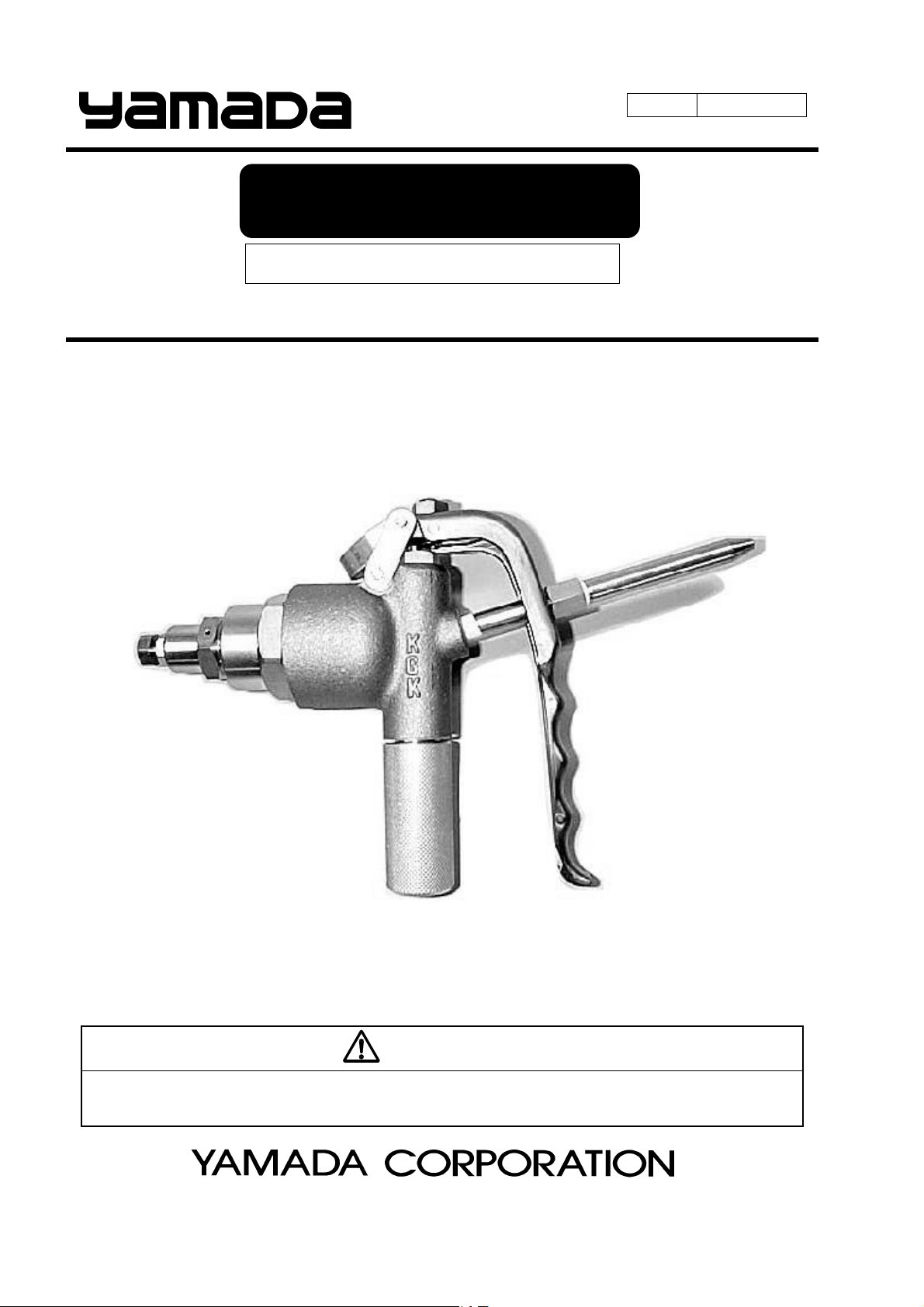
INSTRUCTION
METERING GUN
MODEL. KGK-100 series
WARNING
Prior to operating this pump, be sure to read this operation manual for safety. After reading the manual, please keep it at
hand any time for your quick reference.
Page 2
[Introduction]
This instruction manual contains important safety information and operational instructions.
Read this manual before installation, operation, maintenance, and repair.
Do not use the product without reading this manual. Thoroughly read and understand all of the product
information, safety information, and warning information in the manual.
If you have any questions, please contact the store you purchased the product or our business office.
[For Safe Operation]
According to the hazard level, all safety notes in this manual are classified into “DANGER”,
“WARNING”, and “CAUTION”.
Be sure to read and observe the safety notes to ensure safety and correct use of this product.
indicates a potentially hazardous situation which, if not avoided, WILL result in
death or serious injury.
indicates a potentially hazardous situation which, if not avoided, COULD result in
death or serious injury.
indicates a potentially hazardous situation which, if not avoided, could result in
injury or property damage.
DANGER
WARNING
CAUTION
- Table of Contents -
[Introduction] ........................................................................................... 1
[For Safe Operation] ................................................................................. 1
1. Precautions on Use ............................................................................. 2
2. Product Description ............................................................................ 3
3. Principle of Operation ......................................................................... 4
4. Installation and Connection ................................................................ 5
5. Adjustment and Discharge Test ........................................................... 5
6. Troubleshooting .................................................................................. 6
7. Disassembly and Assembly .................................................................. 7
8. Product and Part List for Grease Metering Gun ................................... 9
9. Product and Part List for Adhesive Metering Gun ................................ 14
10. Limited Warranty ............................................................................... 19
1
Page 3
1. Precautions on Use
The following warnings and cautions are very important. Be sure to observe them.
[Operating condition]
- For your safety, read and understand all information provided in this manual.
If you have lost or damaged your instruction manual, please contact us or our distributor to place an
order.
- Never let anyone operate this unit without understanding this manual.
[Installation and piping]
- Before maintenance operation, be sure to stop air, and release the internal pressure (both air and
material) of the product.
- Immediately stop using the product if there is any danger or defect. Be sure to eliminate the cause and
confirm safety before restarting.
- Follow the safety instructions for installation and be sure to use appropriate piping material and size to
avoid leakage and damage.
[Operating method]
CAUTION
CAUTION
WARNING
- Understand this manual completely before operating the machine.
Operators and maintenance personnel are required to read this manual thoroughly before operating or
servicing. Do not handle this machine without understanding the instructions.
- Do not handle unspecified material with this product. It may cause a product failure.
- Do not use this product for improper purposes.
- During operation, high pressure is continuously applied to the inside of the gun. Thus, even when
supply air to the gun is shut off, residual pressure may be trapped inside. Be sure to release residual
pressure completely BEFORE disassembly and repair for maintenance and inspection.
Also, be sure to stop air supply and power supply before disassembly and repair.
2
Page 4
[Disassembly, maintenance and inspection]
WARNING
- Shut off air supply to the product and remove residual pressure completely BEFORE disassembling.
- Alternating the unit may result in personal injury or product malfunction. Please do not try to alter,
modify, or change the machine.
[Shutdown and storage]
- When leaving the product unused for a long time (more than a week) or shutting it down;
- remove material inside completely and wash the product and
- release material supply pressure.
CAUTION
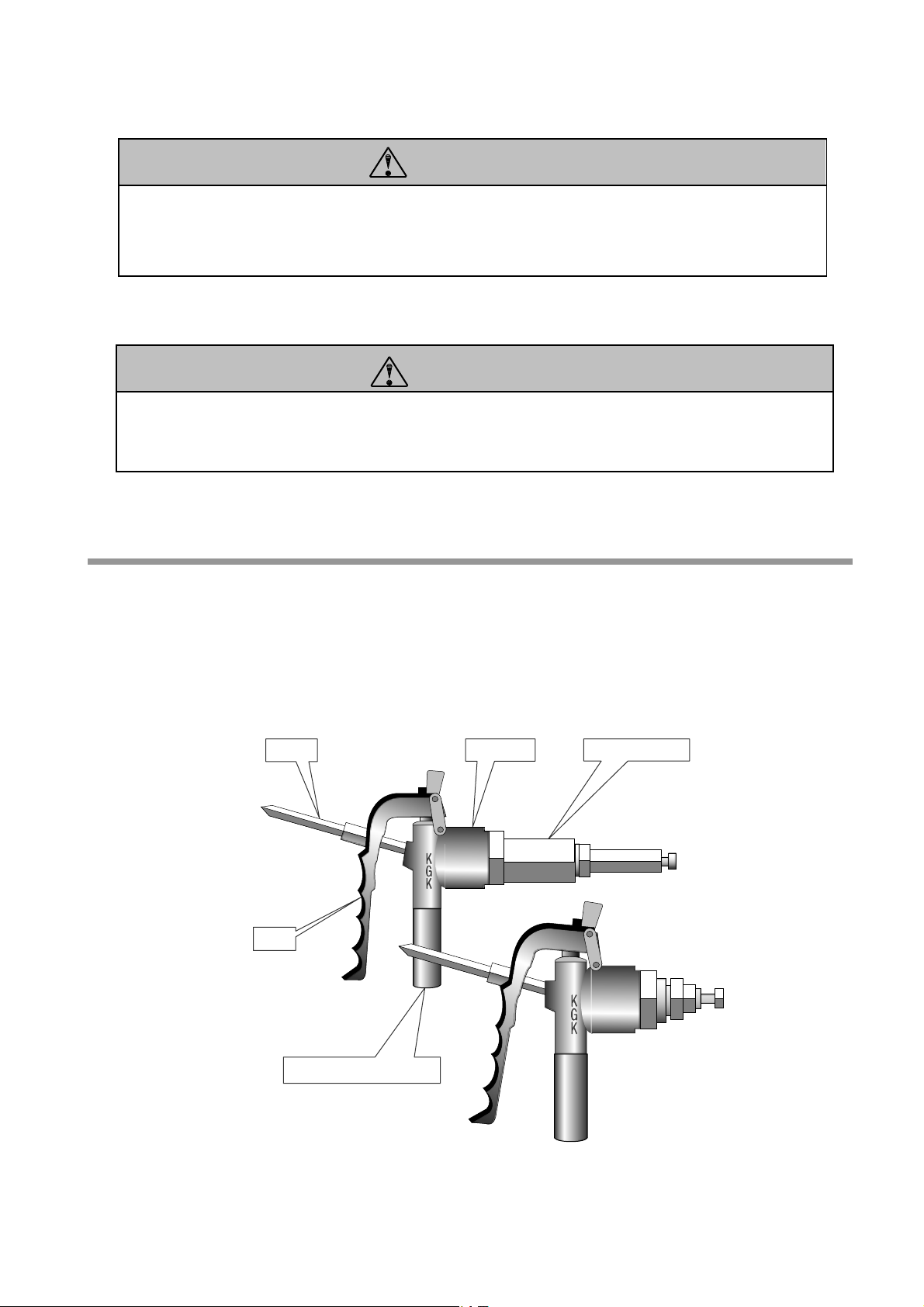
2. Product Description
KGK metering guns are able to apply metered shots of media such as greases and adhesives. By
replacing a built-in metering cylinder, KGK metering valves cover metered shot volumes between 0.3mL
to 20mL. One metered shot is discharged by pulling the lever once and thus material will not be
discharged more than necessary.
Fig.1
Nozzle Metering Cylinder
Lever
Material Connection (Rc1/8)
Gun body
3
Page 5
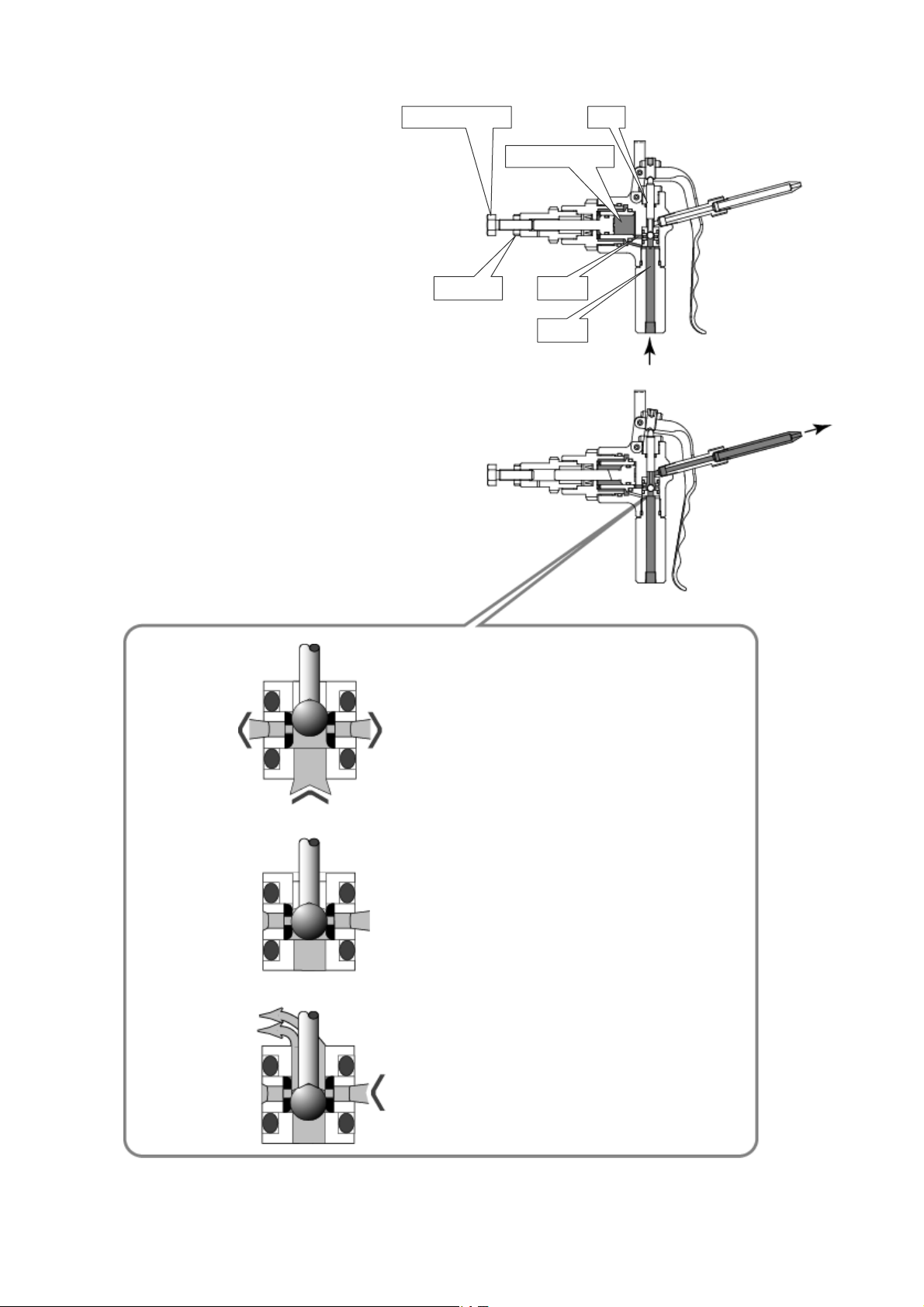
3. Principle of Operation
① Charge (standby)
Material, under pressure from a supply
pump, flows into the rear side of the piston
and constantly pushes the piston forward. At
the same time, material passes through Port
A, lifts up the ball to close Port B, and flows
into the metering chamber. Material in the
metering chamber pushes the piston
backward and thus a metered shot is
charged. The amount of material can be
adjusted to your desirable value with the
adjustment screw. (Fig. 2)
② Discharge
Once the lever is pulled, the piston rod
pushes down the ball to close Port A. Then,
the metering chamber is connected to the
discharge port. The piston is pushed forward
by material pressure from the rear side and
thus a metered shot in the chamber is
finally discharged. (Fig.3)
Fig.4
Fig.5
Fig.6
Adjustment screw Rod
Metering chamber
Lock nut
Port B
Port A
Three way directional valve
① Material comes from the bottom seat lifts up
the ball and flows out of the middle path. The
ball is pressed against the upper seat to close
the outlet so that material will not be
discharged from the upper side.
② The piston rod pushes the ball down. Since
the ball goes down, being sealed by the
rubber in the middle, material will not flow
out even after the ball moves away from the
upper seat.
③ Furthermore, the ball passes through the
path in the middle and seals the inlet on the
bottom seat to stop the flow of material.
Accordingly, the middle path and outlet on
the upper seat are connected and finally
material flows out.
Fig. 2
Fig. 3
4
Page 6
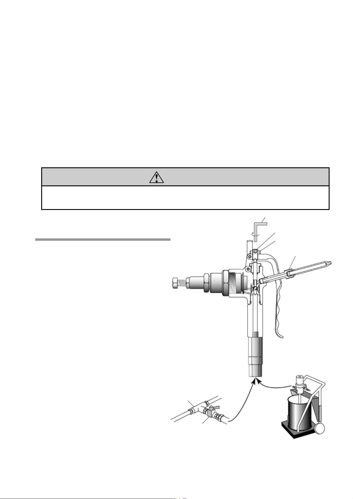
4. Installation and Connection
① Connect a material supply pump or an outlet of a pipe to the metering gun using a hose. (The connecting port
of the gun is Rc1/8.)
It is recommended to attach 850K513 Swivel (sold separately) to the connecting port of the gun for easy
operation. (Fig.7)
② Install your metering gun as close as possible to the equipment or its inlet port you are going to work on.
③ Trapped air in material being metered will be compressed through a pump, pipe, hose, and metering gun
and expand when material is discharged. As a result, the metering gun will have difficulty stopping
discharge and thus it may seem to be leaking. Also, each shot will vary.
Since air is discharged together with material, be sure to expel trapped air completely when using the gun
for the first time and after replacing a material container.
CAUTION
- Dust and dirt, if contained in material, will damage the sealing part of the valve and cause material leak.
Be sure to keep material clean.
5. Adjustment and Discharge Test
① Supply material to the gun. The rod lifts up
the lever with material pressure and the
lever opens. At this time, if material leaks
from the nozzle, check if the lever has a
slight play back and forth at first. Then, if
the lever touches connector, loosen connector.
If material still leaks, loosen the adjustment
screw using a hex wrench until leak stops
and then tighten the locknut temporarily.
② With the lever pulled, perform a discharge
test. If a desired metered shot is discharged,
tighten the locknut. When material flows
out persistently, tighten the locknut with the
lever pulled until material flow stops.
Fig.7
Hex wrench
Adjustment screw
Lock nut
Connector
Te e
High pressure
ball valve
Material feed pump
5
Page 7
- Be sure to shut off the air supply to a supply pump and set the material pressure (primary pressure) to
zero. Leaving a metering valve under pressure will be a cause of material leak or some other problem.
- Once a metered shot is dispensed, be sure to put the valve back to the standby condition.
- Do not use material which contains dirt and dust. Seal parts will be damaged, causing a material leak.
PRECAUTION FOR USE
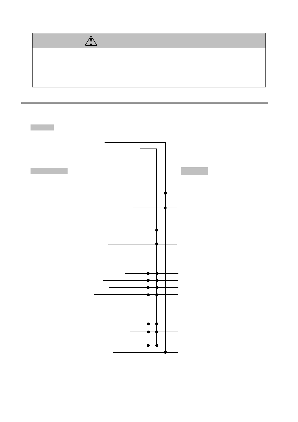
6. Troubleshooting
<Problem>
- Material cannot be discharged.
- Material comes out during Recharge or Standby.
- Material leaks.
<Possible Cause>
Metering gun (external factor)
- Material is not being delivered.
- Material supply pressure (primary pressure)
exceeds the specified pressure of the metering gun.
- Adjustment at the initial use or after repair was
not done.
- Air inside the gun is not released.
Metering gun body
- Ball or valve seat is damaged or worn out
- O ring is damaged or worn out.
- Side ring is damaged or worn out.
- Adjustment screw is loose.
Metering cylinder
- Inner surface of cylinder is damaged or worn out.
- Outer surface of piston, packing, or sleeve is
damaged or worn out.
- O ring is damaged or worn out.
- Adjustment screw is over tightened.
<Solution>
- Check the supply pump and supply
air.
- Check air pressure in the supply
pump (primary pressure = pump
ratio × air pressure)
- Perform Adjustment and Discharge
Test on the previous section.
- Release air completely.
- Replace with new ones.
- Replace with new ones.
- Replace with new ones.
- Readjust the screw and securely
tighten it with a locknut.
- Replace with new ones.
- Replace with new ones.
- Replace with new ones.
- Adjust the adjustment screw to your
desirable shot amount and then
secure it with a locknut.
6
Page 8

A
w
A
CAUTION
- Be sure to use material compatible with the material used in the O ring and packing. Use of
inappropriate material can cause a leak or product malfunction.
- When using a special kind of material, adjustment of the joint of the valve and sleeve may be needed. In
such case, please contact us or your local retailer.
7. Disassembly and Assembly
CAUTION
- Release residual pressure completely BEFORE disassembling metering valves.
- Wash the parts with wash oil and apply a thin layer of lithium grease BEFORE reassembling.
Be extremely careful not to let dust and dirt attach to any of the parts.
7-1. Disassembly
① Unscrew the metering cylinder to remove it from the metering gun
body. Remove two O rings from the body. (Fig.8)
② Unscrew connector and remove it from the body with the nozzle
attached. (Fig.9)
Metering cylinder
O ring
O ring
E type retaining ring
Lock nut
Lever
djustment screw
Was h er
Hook
Pivot pin
Was h er
E type retaining
ring
Connector
Nozzle
③ Remove the E type retaining ring on the one
side of the pivot pin connecting the hook and
lever and pull put the pivot pin from the link.
Then, the hook and lever can be removed.
④ Remove the E type retaining ring on the one
side of the pivot pin connecting the link and
body and pull out the pivot pin from the body.
Then, the link can be removed.
⑤ Unscrew the lock nut on the lever and remove
Fig.9
it from the lever.
Hex wrench
djustment scre
Connector
Lever
Fig.8
7
Page 9

V
V
⑥ Unscrew to remove the gland bushing and remove the rod and
O ring from the body. (Fig.10)
⑦ Unscrew to remove the grip and remove the O ring.
⑧ Remove the valve seat, O ring, side ring, and ball from the body.
7-2. Assembly
① Put the parts on the bottom hole of the body in the following order:
valve seat, O ring, side ring with ball inside, o ring, and valve set.
Then securely tighten the grip with o ring attached.
② Put the O ring on the upper hole of the body first, then screw the
gland bushing tightly, and finally insert the rod.
③ Attach the retaining ring, washer, and link in this order to one side
of the pivot pin and insert the pin into body. Then secure the other
side with the link, washer, and the retaining ring.
④ Attach the adjustment screw to the lever and secure it with a lock
nut.
⑤ Set the hook first and then the lever to the inside of the link. Then,
secure with the pivot pin attached on ③ above. Be sure to fit the
rod head in the tapered hole of the adjustment screw. If failed, the
lever will not work.
⑥ Screw to insert the connector with the nozzle attached into the body
through the hole on the side of the lever.
⑦ Insert the o ring to the side hole of the body and securely tighten
the metering cylinder.
Pivot pin
Retaining ring
Was h er
Link
Ball valve
Retaining ring
Was h er
Link
Grip
O ring
alve seat
O ring
Side ring
O ring
alve seat
O ring
Gland bushing
Rod
Fig.10
CAUTION
- When reassembling the disassembled meter valve, be sure to replace O Rings and Packings with new
ones at the same time as defective parts.
8
Page 10

8. Product and Part List for Grease Metering Gun
8-1 Metering Gun
1 2
MODEL LIST
1mL 686427 800K365 800K856
3mL 686428 800K365 800K857
5mL 686429 800K365 800K858
10mL 686430 800K365 800K859
20mL 686431 800K365 800K860
8-2 Dimensions
(181)
(1)
(137) A B C
9
Size Product No.
Size A B C* D
1mL
3mL
5mL
10mL
20mL
①Switching
Valve
49 38 29.5 101
49 55 27.5 101
49 73 30.5 101
49 96 39.5 101
49 144 64.5 101
*set a maximum value
②Cylinder
D
Page 11

8-3 Metering Gun Body
800K365 Metering Gun Body
1
2
3
No Parts No. Description
1 700K199 Nozzle 1 11 640K011 O ring 2
2 701K300 Connector 1 12 701K297 Valve seat 2
3 703K841 Lever 1 13 701K294 Body 1
4 701K291 Adjustment screw 1 14 640K014 O ring 1
5 627K462 Nut 1 15 701K298 Grip 1
6 701K293 Gland bushing 1 16 703K842 Hook 1
7 640K004 O ring 1 17 703K843 Link 2
8 701K295 Rod 1 18 701K299 Pivot pin 2
9 630K683 Ball 1 19 631K941 E type retaining ring 4
10 800K367 Side ring assembly 1
Q'ty
No Parts No. Description
10
11
12
13
14
15
4
5
6
7
8
9
16
17
18
19
3
Q'ty
10
Page 12

8-4 Metering Cylinder
800K856 Metering Cylinder (1mL) 800K857 Metering Cylinder (3mL)
4 5 6 7 8 9 10 11 12
3
2
1
2 3 4 5 6 7 8 9 10 11
1
12
No Parts No. Description Q'ty
1 703K014 Piston 1
2 644K006 O ring 1
3 644K116 O ring 1
4 701K450 Cylinder 1
5 644K118 O ring 1
6 703K015 Housing 1
7 680K185 Packing 1
8 680K328 Back up ring 1
9 770K285 Sleeve 1
10 703K016 Retainer 1
11 627K491 Nut 1
12 701K198 Adjustment screw 1
No Parts No. Description Q'ty
1 703K014 Piston 1
2 644K006 O ring 1
3 644K116 O ring 1
4 701K450 Cylinder 1
5 644K118 O ring 1
6 703K015 Housing 1
7 680K185 Packing 1
8 680K328 Back up ring 1
9 770K285 Sleeve 1
10 703K016 Retainer 1
11 627K491 Nut 1
12 701K198 Adjustment screw 1
800K858 Metering Cylinder (5mL)
1 2 3 4 5 7 8 9 10 11 12 13
6
No Parts No. Description Q'ty
1 701K446 Cylinder 1
2 644K116 O ring 1
3 703K021 Housing 1
4 644K118 O ring 1
5 644K013 O ring 1
6 645K643 Back up ring 1
7 703K020 Piston 1
8 680K139 Packing 1
9 680K138 Back up ring 1
10 770K226 Sleeve 1
11 703K022 Retainer 1
12 627K493 Nut 1
13 701K194 Adjustment screw 1
11
Page 13

800K859 Metering Cylinder (10mL)
1 2 3 4 5 7 8 9 10 11 12 13
6
No Parts No. Description
1 701K429 Cylinder 1 8 680K238 Packing 1
2 644K116 O ring 1 9 770K268 Back up ring 1
3 703K024 Housing 1 10 770K236 Sleeve 1
4 644K118 O ring 1 11 703K025 Retainer 1
5 644K016 O ring 1 12 627K493 Nut 1
6 645K646 Back up ring 1 13 701K191 Adjustment screw 1
7 703K023 Piston 1
Q'ty
No Parts No. Description
Q'ty
800K860 Metering Cylinder (20mL)
54 6 7 8 9 10 11 12 13
1 2
3
No Parts No. Description
1 703K026 Piston 1 8 680K238 Packing 1
2 644K016 O ring 1 9 770K268 Back up ring 1
3 645K646 Back up ring 1 10 770K236 Sleeve 1
4 644K116 O ring 1 11 703K028 Retainer 1
5 701K931 Cylinder 1 12 627K493 Nut 1
6 644K118 O ring 1 13 703K504 Adjustment screw 1
7 703K027 Housing 1
Q'ty
No Parts No. Description
Q'ty
12
Page 14

8-5 Specifications
Product No.
Model
686427 686428 686429 686430 686431
KGK-112 KGK-114 KGK-115 KGK-116 KGK-117
Greases, High Viscosity Oils
- Please contact us if you are going to use any material such as silicone grease or
molybdenum disulfide grease which will affect the operation of a valve.
Applicable Material
Capacity
- Any material which contains particles such as aggregate or fast drying type of
material is NOT applicable.
- Wetted parts in a metering gun are made of steel and aluminum and seal parts
are made of NBR and polyurethane.
Make sure that material you are going to use is compatible with these parts.
Shot Range
Shot Accuracy
1mL 3mL 5mL 10mL 20mL
0.3-1mL 0.5-3mL 1-5mL 3-10mL 5-20mL
Maximum Operating Pressure ± 2 %
Withstanding pressure 20MPa
Operating Temperature 30MPa
Weight Room Temperature
Product No. 1.0 kg 1.1 kg 1.2 kg 1.3 kg 1.5 kg
Note: Viscosity of material will vary according to use conditions.
13
Page 15

9. Product and Part List for Adhesive Metering Gun
9-1 Metering Gun
1 2
MODEL LIST
Size Product No.
1mL 686432 800K375 800K376
3mL 686433 800K375 800K377
5mL 686434 800K375 800K378
10mL 686435 800K375 800K379
20mL 686436 800K375 800K572
9-2 Dimensions
(181)
(1)
(137)
①Switching
Valve
A B C
Size A B C* D
1mL 49 23.5 26.5 101
3mL 49 38 27.5 101
5mL 49 55 37.5 101
10mL 49 67 41.5 101
20mL 49 118 42.5 101
②Cylinder
D
*set a maximum value
14
Page 16

9-3 Metering Gun Body
800K375 Metering Gun Body
1
2
3
No Parts No. Description
1 700K199 Nozzle 1 11 643K011 O ring 2
2 701K300 Connector 1 12 701K297 Valve seat 2
3 703K841 Lever 1 13 701K294 Body 1
4 701K291 Adjustment screw 1 14 643K014 O ring 1
5 627K462 Nut 1 15 701K298 Grip 1
6 701K293 Gland bushing 1 16 703K842 Hook 1
7 640K004 O ring 1 17 703K843 Link 2
8 701K295 Rod 1 18 701K299 Pivot pin 2
9 630K683 Ball 1 19 631K941 E type retaining ring 4
10 795K015 Side ring assembly 1
Q'ty
No Parts No. Description
10
11
12
13
14
15
4
5
6
7
8
9
16
17
18
19
3
Q'ty
15
Page 17

9-3 Metering Cylinder
800K376 Metering Cylinder (1mL) 800K377 Metering Cylinder (3mL)
3 4 5 6 7
12
1110
1 2 3 54 6 7 8 9 10
1 2
8 9
111213
No Parts No. Description Q'ty
1 701K449 Packing retainer 1
2 643K006 O ring 1
3 701K450 Cylinder 1
4 643K116 O ring 1
5 701K452 Piston 1
6 643K118 O ring 1
7 701K451 Housing 1
8 770K111 Packing 2
9 770K113 Packing 1
10 702K141 Retainer 1
11 627K491 Nut 1
12 701K198 Adjustment screw 1
No Parts No. Description Q'ty
1 701K353 Packing retainer 1
2 643K116 O ring 1
3 643K118 O ring 1
4 701K354 Cylinder 1
5 701K355 Housing 1
6 701K356 Piston 1
7 701K357 Retainer 1
8 701K358 Cover 1
9 627K491 Nut 1
10 701K198 Adjustment screw 1
11 770K125 Packing 1
12 770K112 Packing 2
13 643K011 O ring 1
800K378 Metering Cylinder (5mL)
1 2 3 4 5 6 7 8 9
1011121314
No Parts No. Description Q'ty
1 701K455 Piston 1
2 643K116 O ring 1
3 643K118 O ring 1
4 701K446 Cylinder 1
5 701K456 Housing 1
6 701K453 Retainer 1
7 701K457 Cover 1
8 627K493 Nut 1
9 701K191 Adjustment screw 1
10 770K125 Packing 1
11 770K112 Packing 2
12 630K582 Retaining ring 1
13 701K458 Washer 1
14 643K013 O ring 1
16
Page 18

800K379 Metering Cylinder (10mL)
2 3 4 5 6 7
10 11 12 13 14
1
8 9
No Parts No. Description
1 643K016 O ring 1 8 770K131 Packing 2
2 643K116 O ring 1 9 770K130 Packing 1
3 701K463 Washer 1 10 701K461 Housing 1
4 630K584 Retaining ring 1 11 701K459 Packing retainer 1
5 643K118 O ring 1 12 701K457 Cover 1
6 701K429 Cylinder 1 13 627K493 Nut 1
7 701K460 Piston 1 14 701K191 Adjustment screw 1
Q'ty
No Parts No. Description
Q'ty
800K572 Metering Cylinder (20mL)
No Parts No. Description
1 2 3 4 5 6 7 8 9 10 11
12 13 14
Q'ty
No Parts No. Description
1 702K729 Piston 1 8 702K731 Cover 1
2 643K116 O ring 1 9 701K459 Packing retainer 1
3 701K931 Cylinder 1 10 627K493 Nut 1
4 643K118 O ring 1 11 701K191 Adjustment screw 1
5 702K730 Housing 1 12 643K016 O ring 1
6 770K131 Packing 2 13 701K463 Washer 1
7 770K130 Packing 1 14 630K584 Retaining ring 1
Q'ty
17
Page 19

9-5 Specifications
Product No.
Model
686432 686433 686434 686435 686436
KGK-112T KGK-114T KGK-115T KGK-116T KGK-117T
Adhesive
- Any material which contains particles such as aggregate or fast drying type of
Applicable Material
material is NOT applicable.
- Wetted parts in a metering gun are made of steel and aluminum and seal parts
are made of fluorine resin.
Make sure that material you are going to use is compatible with these parts.
Capacity
Shot Range
1mL 3mL 5mL 10mL 20mL
0.3-1mL 0.5-3mL 1-5mL 3-10mL 5-20mL
Shot Accuracy ± 2 %
Maximum Operating Pressure 20MPa
Withstanding pressure 30MPa
Operating Temperature Room Temperature
Weight 1.0 kg 1.1 kg 1.2 kg 1.3 kg 1.5 kg
Note: Viscosity of material will vary according to use conditions.
18
Page 20

10. Limited Warranty
If an abnormality occurs during normal operation in accordance with the operating instructions and other operating cautions
within the warranty period (12 months after date of purchase) that can be attributed to a manufacturing defect, the defective
parts of this product will be serviced or the product will be replaced free of charge. However, this warranty will not cover
compensation for incidental damage or any malfunction listed below.
1. Warranty period
This warranty will be valid for a period of 12 months after the date of purchase.
2. Warranty
If, during the warranty period, any of the material of the genuine parts of this product or the workmanship of this product is
found defective, and is so verified by our company, the servicing cost will be fully born by our company.
3. Exclusion
Even during the warranty period, this warranty does not cover the following:
1) Malfunction arising from use of parts other than manufacturer-specified genuine parts
2) Malfunction arising from misuse or operating errors, or lack of storage or maintenance care
3) Malfunction arising from use with a fluid that may cause corrosion, inflation or dissolution of the component parts of the
product
4) Irregularity arising from repair made by other than by our firm, our regional office, dealer or authorized service
personnel
5) Malfunction arising from modification of the product by other than authorized service personnel
6) Wear and tear of parts that must be regularly replaced in the course of normal operation, such as packings, O rings,
balls, and valve seats
7) Malfunction and/or damage due to transportation, moving or droppage of the product after purchase
8) Malfunction and/or damage due to fire, earthquake, flood or other force majeure
9) Malfunction arising from use of compressed air that contains impurities or excessive moisture, or use of gases or fluids
other than the specified compressed air
10) Malfunction arising from use with a fluid that causes excessive abrasion or use of lubricating oil other than that
specified for this product
Furthermore, this warranty does not cover the rubber parts, or other parts that are subject to wear in normal operation, used
in this product and its accessories.
4. Parts
Parts for this product will be kept available for 5 years after discontinuation of production. Once 5 years have elapsed after
close of production, availability of parts for this product cannot be guaranteed.
19
Page 21

MEMO.
Page 22

Manufactured by
YAMADA
CORPORATION
INTERNATIONAL DEPARTMENT
No.1-3, 1-Chome, Mimami-Magome, Ohta-Ku, Tokyo, 143-8504, Japan
PHONE : +81-(0)3-3777-0241
FAX : +81-(0)3-3777-0584
201108 100-494YO
 Loading...