

Page 1
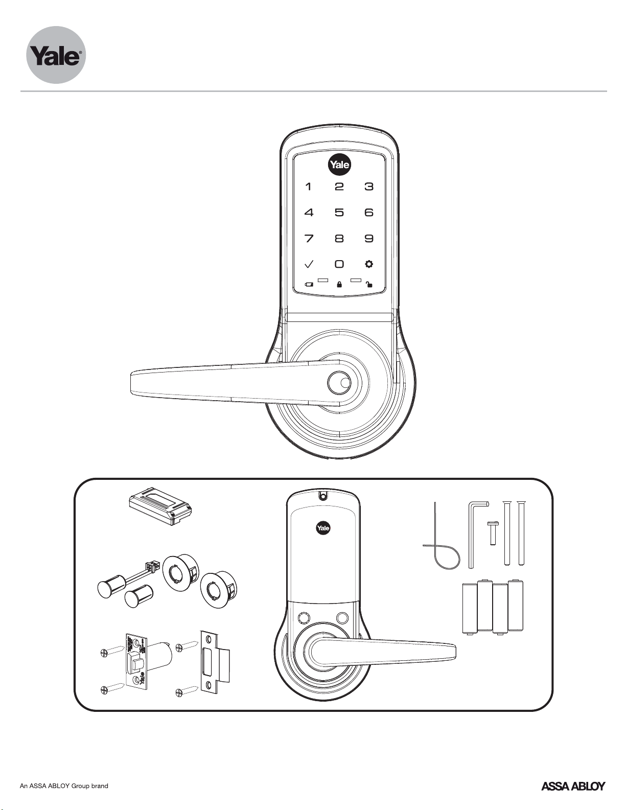
nexTouch
™
Touchscreen and Push Button Access Cylindrical Lock
Installation and Programming Instructions
3/32"
Optional
AA
Optional
AA
AA
Retrofitting or modifying this product may impact fire rating, safety features and warranty.
Consult with code specifications to ensure compliance with all codes and ratings.
1
P/N 80-9150-0080-010 (10-17)
AA
Page 2
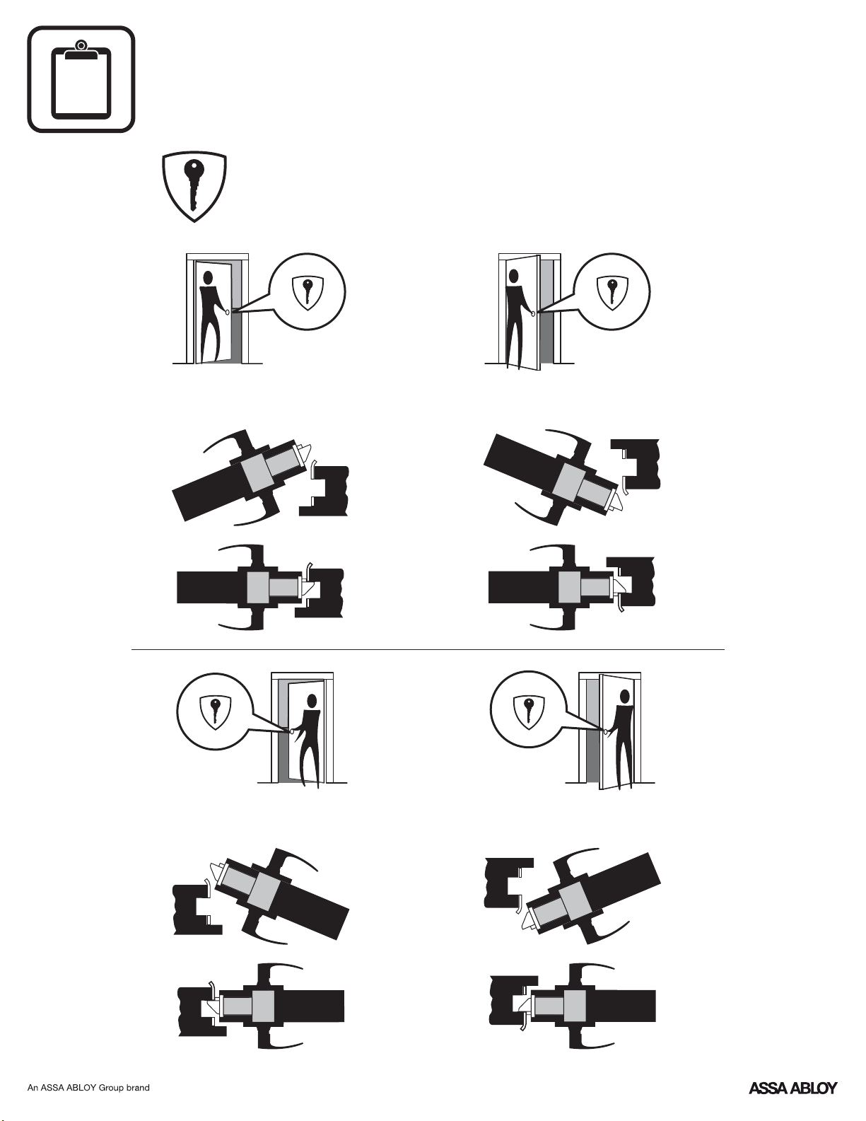
?
Determining Handing
The hand of a door is determined from the secure side of the door. The
term "secure" means the side from which you initially unlock and enter.
Left Hand “ ”, Hinges Left.LH
Open Inward.
Left Hand Reverse " ", Hinges Left.LHR
Open Outward.
Right Hand " ", Hinges Right.RH
Open Inward.
Right Hand Reverse " ", Hinges Right.RHR
Open Outward.
2
P/N 80-9150-0080-010 (10-17)
Page 3
aaaaaaaaaaaaaaaaaaaaaaaa
aaaaaaaaaaaaaaaaaaaaaaaa
aaaaaaaaaaaaaaaaaaaaaaaa
aaaaaaaaaaaaaaaaaaaaaaaa
aaaaaaaaaaaaaaaaaaaaaaaa
aaaaaaaaaaaaaaaaaaaaaaaaaaa
aaaaaaaaaaaaaaaaaaaaaaaaaaa
aaaaaaaaaaaaaaaaaaaaaaaaaaa
aaaaaaaaaaaaaaaaaaaaaaaaaaa
aaaaaaaaaaaaaaaaaaaaaaaaaaa
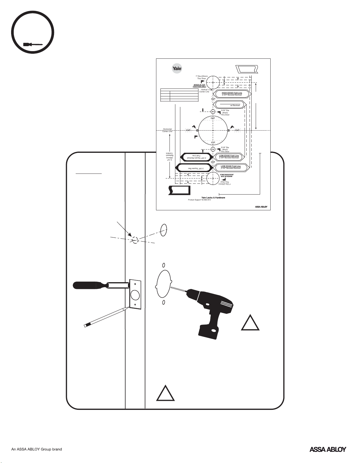
1
Preparing Door
DPS Option
Wood Door:
3/8" Dia. x Thru to
Hole in Door Face
*Metal Door:
3/4" Dia. Thru to
Hole in Door Face
Cylindrical Lock
80-8150-0032-010
nexTouch Cylindrical Locks
NTB610
620NTB
630NTB
640NTB
Horizontal
Center Line
An ASSA ABLOY Group brand
™
nexTouch
Rev C
™
Cylinder Override - Push Button
Cylinder Override - CapTouch
No Cylinder Override - Push Button
No Cylinder Override - CapTouch
Centers
Between
(89mm)
3-1/2"
Reproduction in whole or in part without the express written permission ofYale Security Inc., an Group company is prohibited.ASSA ABLOY
1" Dia.(25mm)
Thru Door
WHEN IN TOP
POSITION ONLY
Vertical
Center Line
CUT
2-3/4" (70mm)
Between Centers
5/32" Dia x 1/8" Deep
(4mm x 3mm)
2 Locations
Both sides of door
CUT CUT
2-1/8" Dia
(54mm)
Thru Door
Metal Frame
DOOR ONLY
SQUARE EDGE
Product Support Tel 800-810- (9473) • www.yalelocks.comWIRE
Yale Locks & Hardware is a division ofYale Security Inc., an Group company.ASSA ABLOY
nexTouch™is a trademark ofYale Security Inc., an ASSA ABLOY Group company.
Fold Line
Fold Line
2-3/8" Square Backset
3/4" (19mm) Dia.
CUT
CUT
2-3/8" Square Backset
CUT
Wood Frame
3/8" (9.5mm) Dia.
ASSA ABLOYCopyright © 2017,Yale Security Inc., an Group company. All rights reserved.
3/8" (9.5mm) Dia.
Wood Frame
3/4" (19mm) Dia.
HIGH ED GE Fold Line
2-3/4" Beveled Backset
HIGH ED GE Fold Line
2-3/8" Beveled Backset
5/16" Dia
(8mm)
Thru Door
5/32" Dia x 1/8" Deep
(4mm x 3mm)
2 Locations
Both sides of door
5/16" Dia
(8mm)
Thru Door
LOW EDG E Fold Line
2-3/8" Beveled Backset
LOW EDG E Fold Line
2-3/4" Beveled Backset
Thru Door
1" Dia.(25mm)
Measure both 3" lines to check scale
HIGH EDGE
BEVELED EDGE
DOOR ONLY
LOW EDGE
Metal Frame
POSITION ONLY
WHEN IN TOP
CAUTION:
If printed from website
Print 1:1 Scale
3"
3-1/2"
(89mm)
Between
Centers
3"
*Metal Door Installations
Supplied plastic collar beMUST
!
installed for to function properly.DPS
3
P/N 80-9150-0080-010 (10-17)
!
Drill holes 1/2 way thru
door then complete from
other side to prevent
splitting.
Page 4
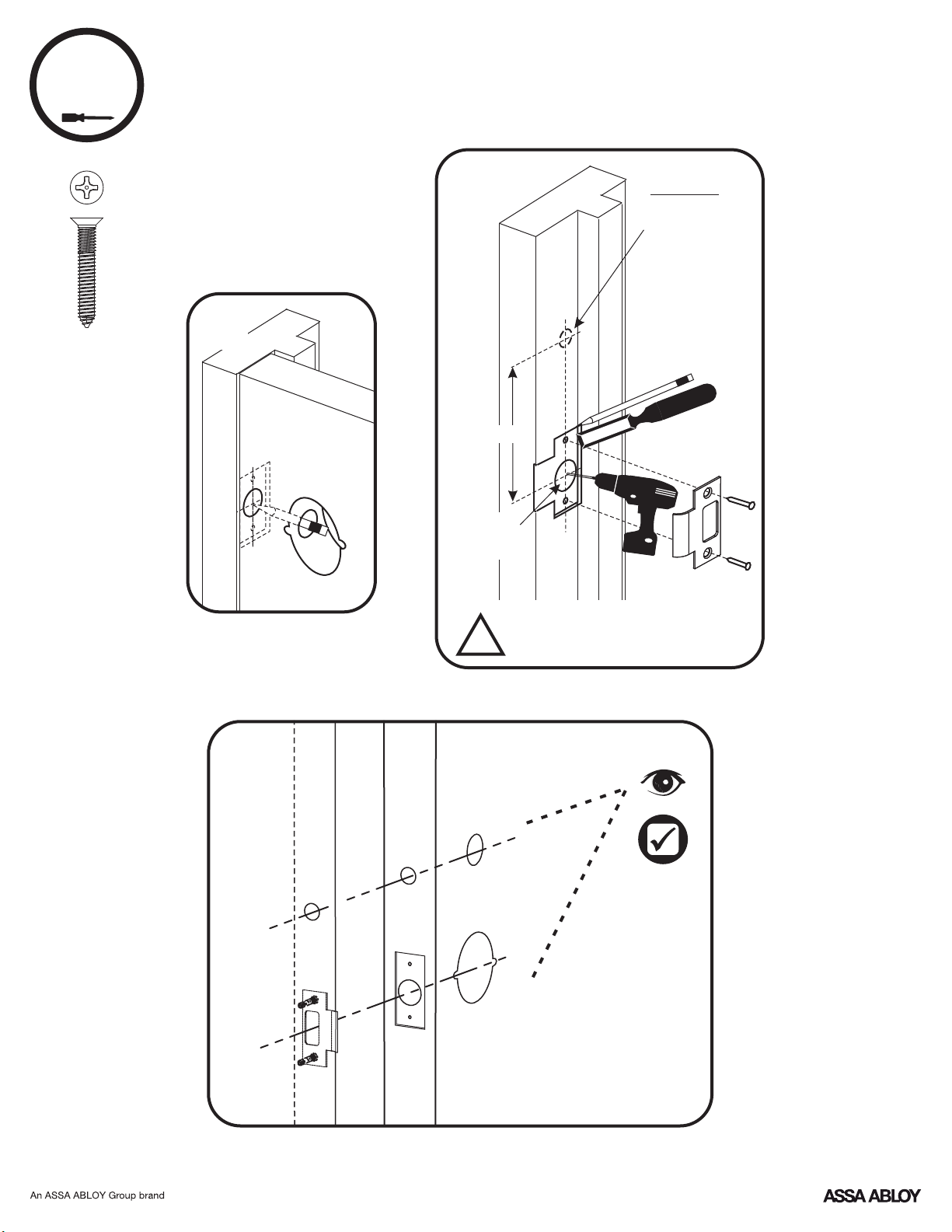
2
Preparing Frame
7-16 / 8-32 x 1" UNCWS
x2
Frame
Inside
of Door
3-1/2"
1" Dia. x
1/2" Deep
!
Frame
*Metal Frame Installations
Supplied plastic collar beMUST
installed for to function properly.DPS
DPS Option
Wood Frame:
3/8" Dia. x 1"
*Metal Frame:
3/4" Dia. x 1"
See Instruction
A7983B
DoorFrame
4
P/N 80-9150-0080-010 (10-17)
Page 5
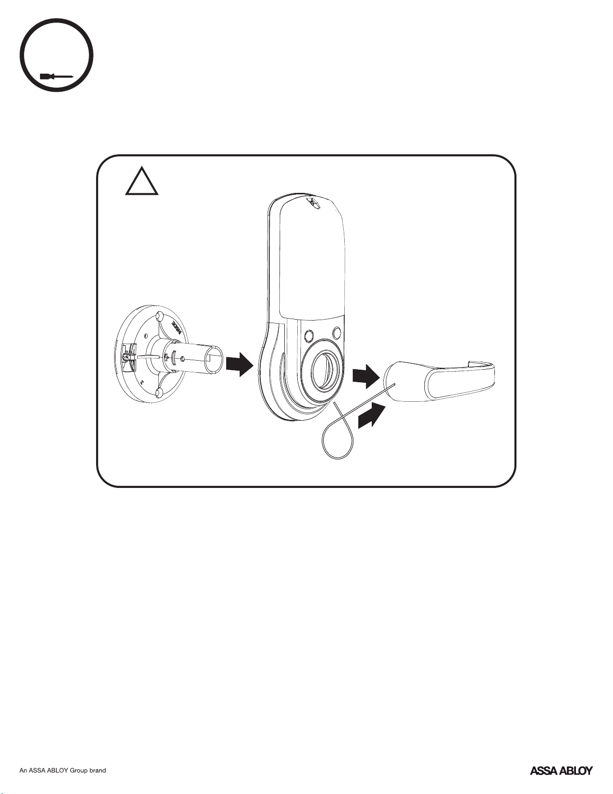
3
Preparing Inside Escutcheon
Do not take apart the
outside assembly.
!
3
2
1
5
P/N 80-9150-0080-010 (10-17)
Page 6
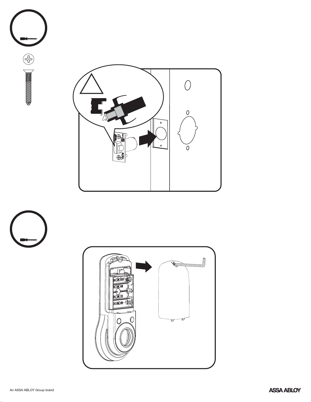
4
x2
Installing Latchbolt
2-3/8" Latchbolt for thin doors sold separately.
See Installation Options.
7-16 / 8-32 x 1" UNCWS
Curved edge of latchbolt
faces direction door closes.
!
Inside of Door
5
Removing Battery Cover
6
P/N 80-9150-0080-010 (10-17)
Page 7
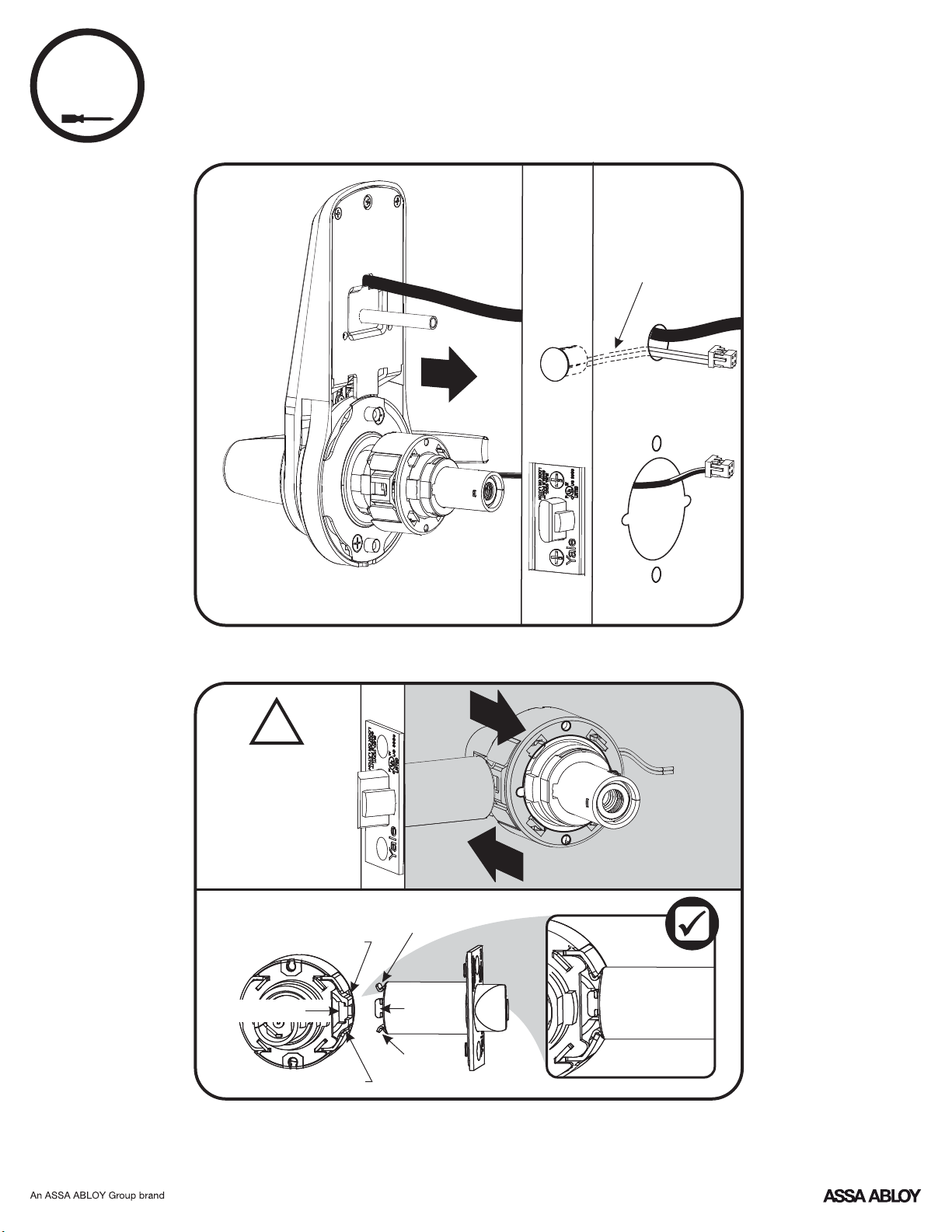
6
Installing Outside Assembly
Thin door gaskets sold separately.
See Installation Options.
Inside of Door
Optional DPS
!
Two moving "T" tabs
must be fully captured
in retractor pocket.
Mounting Flanges
must be in Mounting
Flange Pockets.
View from Outside of Door
Mounting Flange Pocket
Retractor Pocket
Mounting Flange Pocket
Mounting Flange
"T" Tabs
Mounting
Flange
2
1
Inside of Door
7
P/N 80-9150-0080-010 (10-17)
Page 8
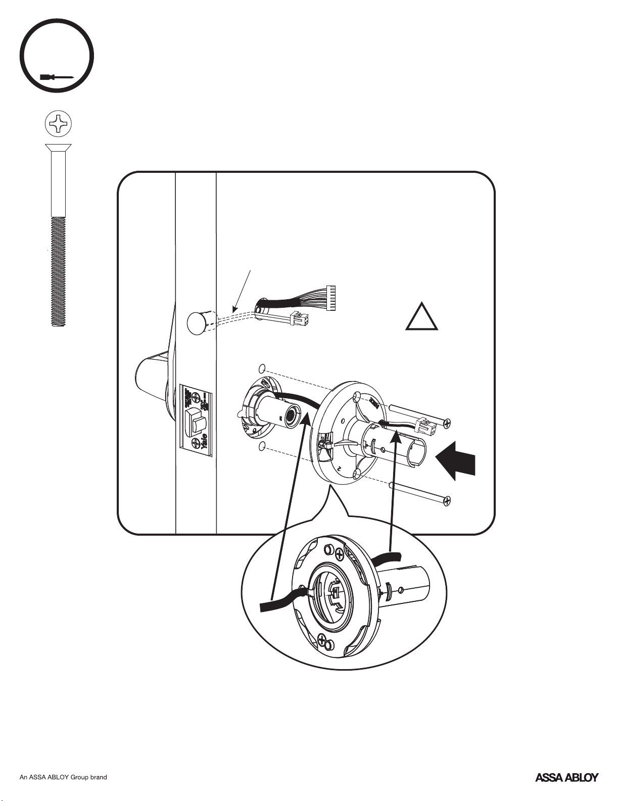
7
x2
Installing Inside Support Assembly
10-32 x 2-1/2" PFHMS
Inside of Door
Optional DPS
!
Do Not
Overtighten Screws
8
P/N 80-9150-0080-010 (10-17)
Page 9
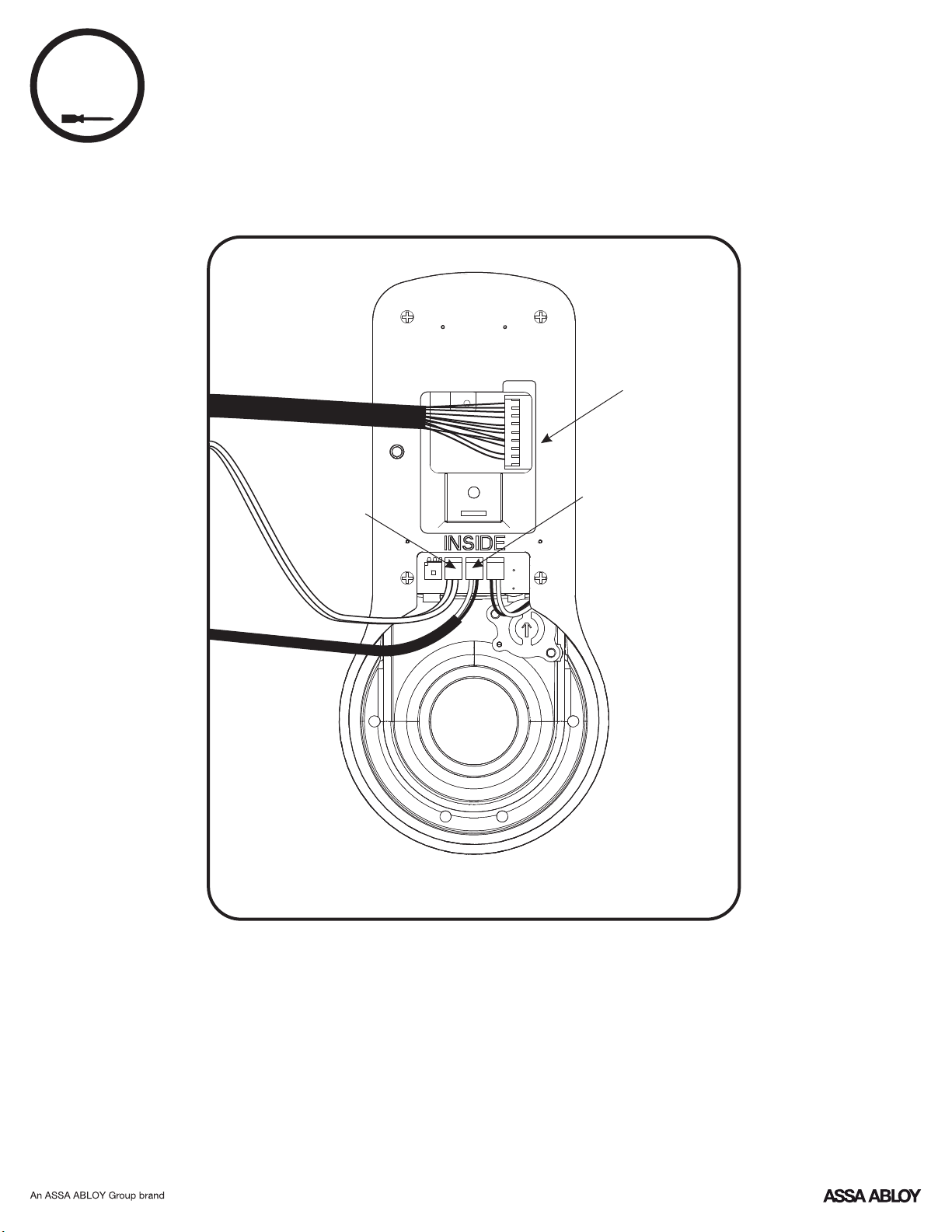
8
Attaching Cables
Touchpad
Connection
Motor
Connection
Optional
DPS
Connection
9
P/N 80-9150-0080-010 (10-17)
Page 10

9
Installing Inside Escutcheon
Thin door gaskets sold separately.
See Installation Options.
!
Avoid pinching
cables
Testing Inside Lever Operation
10
P/N 80-9150-0080-010 (10-17)
Page 11

10
Installing Batteries & Cover
"Welcome to Yale."
!
Optional Network or Yale
Accentra Key module must be
installed batteries. SeeBEFORE
Installation Options.
Congratulations, you've installed the Yale nexTouch Lock!
Continue on next page to customize your product.
™
11
P/N 80-9150-0080-010 (10-17)
Page 12

Installation Options
Adjusting for 1-3/8" Door
Order 1-3/8" Thin Door Kit: 14-4761-0106
!
(if necessary)
Outside Gasket Inside Gasket2-3/8" Latchbolt
Privacy SwitchDPS
Door Position Switch Option
enables Privacy feature
Inside of Door
Metal Frame/Door Installations
Supplied plastic collars beMUST
installed for to function properly.DPS
Network or Yale Accentra Key Module
12
P/N 80-9150-0080-010 (10-17)
Page 13

9Volt Battery
Override Terminal
Programming Instructions
Low Battery
Indicator
Exterior Escutcheon
Unlock
Indicator
Lockout Mode
Indicator
Speaker
Interior Escutcheon
Privacy
Button
Lock Activation
OR
Master Code must be created before any further programming.PIN
Max User Codes = 500
13
P/N 80-9150-0080-010 (10-17)
Page 14

1
Creating Master CodePIN
Creating a Master Code must be performed upon installation or after resettingPIN
the lock to factory default. Programming and use of lock is not possible until this
step has been successfully completed.
"Register Master
Press
Code. Press the gear
key to continue."
Enter 4-8 digit
Master Code.PIN
Press
"Enter a 4-8 digit
code. Press thePIN
gear key to continue."
"Registered."
"Completed."
14
P/N 80-9150-0080-010 (10-17)
Page 15

2
Creating User CodesPIN
Master code must be created first.PIN
*Max User Codes = 500
"Menu Mode,
enter number."
Enter Master
codePIN
Press
Press
Press
"Press 1 to
register a code."
"Register User code.
Press the gear key
to continue."
"Register User code.
Press the gear key
to continue."
Press
Press
" code registration.PIN
Enter a 4-8 digit code.PIN
Press the gear key
to continue."
15
P/N 80-9150-0080-010 (10-17)
Page 16

2
Creating User Codes con'tPIN
Enter 4-8 digit codePIN
followed by
"Registered.
Press the check key to
complete. Press the gear
key to continue."
Adding more User Codes:
Press
Enter 4-8 digit codePIN
Press
"Registered.
Press the check key to
complete. Press the gear
key to continue."
To end programming:
Press
"Completed."
16
P/N 80-9150-0080-010 (10-17)
Page 17

Locking & Unlocking Door with
3
Registered Master or User CodePIN
Enter CodePIN
Press
17
P/N 80-9150-0080-010 (10-17)
Page 18

Testing Outside Lever Operation
4
Locking Door with Privacy Button
18
P/N 80-9150-0080-010 (10-17)
Page 19

Resetting Lock to Factory Default
Reset
Button
Interior Escutcheon
Lever Removal Tool Hex Wrench
When lock is reset to factory defaults all user codes (including the Master code*)PIN
are deleted and all programming features are reset to original default settings (see
Factory Settings).
IMPORTANT: The outside assembly remains assembled.
1. Remove inside lever with the
supplied lever removal tool.
2. Remove the battery cover with
supplied hex wrench and then
remove batteries.
3. Remove the 10-32 x 3/4" pan
head screw from the center of the
battery housing.
4. Remove the interior escutcheon
from the door to access the reset
button on back of escutcheon.
Cables may stay connected. (See
illustration at above for location of
the reset button.)
Upon reset, Master Code creation is the only option available and must bePIN
performed prior to any other programming of the lock.
5. Reinstall four (4) batteries.AA
6. Press the reset button for 3
seconds.
7. While continuing to press the
reset button, temporarily remove
one (1) battery.AA
8. Reinstall the battery.
9. Release reset button and wait
approximately 15 seconds.
Speaker will announce "Welcome
to Yale."
10. Reassemble escutcheon by
reversing steps 1-4.
19
P/N 80-9150-0080-010 (10-17)
Page 20

Definitions
All Code Lockout Mode: This feature is enabled by the Master code. When enabled, it restricts all user (except
Master) code access. When attempting to enter a code while the unit is in Lockout, the locked padlockPIN RED
will appear on the screen. (Main Menu selection #6.)
Automatic Re-lock Time: After a successful unlock, the unit will re-lock automatically after 5 seconds or for a
duration selected in the (Main Menu selection #3 then #1).Advanced Lock Settings
Language Setting Mode: Choose English (1), Spanish (2) or French (3) for the lock's voice prompts. (Main
Menu selection #5.)
Low Battery: When battery power is low, the Low Battery Warning indicator flashes . If battery power isRED
completely lost, use the 9Volt battery override. To use the 9V battery override apply 9V battery, in either
direction, to terminals on the touchscreen for backup power option. Activate the touchscreen and enter your pin
code to unlock the door.
Master Code: It must be createdPIN The Master code is used for programming and for feature settings.PIN
prior to programming the lock. The Master code will also operate (unlock/lock) the lock.
Network Module Setting: With the optional Network Module installed, this setting becomes available (Main
Menu selection #7) and allows the lock to connect with a network controller.
One Touch Locking: When the unit is unlocked, activating the touchscreen will lock the unit (during Automatic
Re-lock duration or when Automatic Re-lock is disabled). When One-Touch Re-lock is in use anynot (disabled),
valid code will re-lock the lock. (Main Menu selection #3 then #3.)PIN
Privacy Button to Lock Door: If Automatic Re-lock is disabled, a short 1 second press of this button will lock the
door.
Privacy Mode: With optional Door Position Switch installed, Privacy Mode enabled thru Menu Mode and door
closed, all keypad functions can be disabled with a 3 second press of the Privacy Button. Privacy Mode is
disabled by default. Enable Privacy Mode thru Main Menu selection #3 then #4. With door closed, press and
hold the privacy button until voice prompt indicates Privacy Mode is enabled. Privacy Mode duration ends when
door is opened and voice prompt indicates Privacy Mode is disabled.
Shut Down Time: The unit will shut down for sixty (60) seconds and not allow operation after the wrong code
entry limit (5 attempts) has been met. When the unit is in Shut down, the keypad will be flashing.
Tamper Alert: Audible alarm sounds if attempting to forcibly remove outside lock from door.
User Code:PIN The User code operates the lock. Maximum number of user codes is 500.
Volume Setting Mode: (1)The volume setting for code verification is set to by default; otherwise itPIN HIGH
can be set to or for quiet areas. (Main Menu selection #4.)Low (2) Silent (3)
Wrong Code Entry Limit: After five (5) unsuccessful attempts at entering a valid code, the unit will shutPIN
down and not allow operation. When the unit is in Shut Down, the keypad will be flashing.
20
P/N 80-9150-0080-010 (10-17)
Page 21

Feature Programming Through Menu Mode
Using Master code*PIN
1. Touch screen with back of hand or palm to activate.
2. Enter 4-8 digit master code* followed by key.PIN
Lock Response: "Menu mode, enter number (Enter digit corresponding to the
function to be performed), press the key to continue."
3. Follow the voice commands.
4. Press key to complete the process and conclude the programming session.
*The Master code must be registered prior to any other programming of the lock.PIN
1
Master Code SettingPIN
User Codes
Advanced Lock Settings
M
2
3
M
Enter
Delete
Automatic Re-lock
One Touch Locking
Privacy
U
U
Continue
Continue
1-180 Sec
Disable
Enable
Disable
Enable
Disable
Complete
Complete
Continue
Volume Setting
Language Setting
All Code Lockout
**Network Module Setting
**Set-up Digital Keys
High
Low
Silent
English
Spanish
French
Enable
Disable
Join the network
Exit the network
21
P/N 80-9150-0080-010 (10-17)
Complete
Default settings
in bold.
**This function appears only with
Network or Yale Accentra
Key module installed.
Page 22

Programming Troubleshooting
Symptom
Lock does not respond –
door is open and
accessible.
Lock does not respond –
door is locked and
inaccessible.
Unit is on for a while then
shows no reaction. Lights
dim.
Unit chimes to indicate
code acceptance, but the
door will not open.
Unit operates to allow
access, but will not
automatically re-lock.
PIN codes will not register.
Upon entering a codePIN
and pressing key, the
unit displays "invalid code"
error or lock times out without responding.
Upon entering a codePIN
and pressing the key,
the red padlock icon appears
and there are different tones.
The unit operates, but it
makes no sound.
The unit responds
"Low Battery"
Upon entering a codePIN
and pressing the key,
the unit responds " Wrong
number of digits".
Suggested Action
Touchscreen becomes active when pressed w/whole hand.
•
Use a larger area of the hand or fingers and verify contact
with at least 3 areas.
•
If touchscreen numbers are visible, check to see if they
respond when pressed.
Check batteries are installed and oriented correctly (polarity)
•
in the battery case.
Check batteries are in good condition; replace batteries
•
if discharged.
Check to see if touchscreen cable is fully connected
•
and not pinched.
Batteries may be completely discharged.
•
•
Apply 9V battery to terminals on the touchscreen for
emergency power jump option.
•
Batteries do not have enough power. Replace batteries.
Check for another locking device on the door (i.e. deadbolt).
•
Check the door gaps for any foreign objects between door
•
and frame.
Check that the motor cable is firmly connected into the PC
•
board marked " ".MOTOR
Check to see if Auto Re-lock Mode is enabled.
•
If low battery indicator is lit (see below), change batteries.
•
PIN codes must consist of 4 to 8 digits to register.
•
The same code cannot be used for multiple users.PIN
•
Registration/management of codes is set by thePIN
•
authority of the Master Code, which is set first.
Contact the Master user.
•
User codes must be entered within 20 seconds (while
•
touchscreen is active) or process will have to be restarted.
Check or gear cannot be used as part of the code.PIN
•
•
Check to see if All Code Lockout Mode is enabled.
•
Only the Master can enable/disable Lockout Mode.
Contact the Master user.
•
Check to see if All Code Lockout Mode is enabled.
•
Only the Master can enable/disable Lockout Mode.
Contact the Master user.
Check to see if Volume is set to Silent.
•
This is the alert to replace the batteries. Replace all four
•
(4) batteries with new Alkaline batteries.AA
The digits entered were incorrect or incomplete. Re-enter
•
4-8 digits followed by the check key.
NOTE: When batteries are replaced, Network Module locks have a real time clock that will be set
through the User Interface ( ); it is recommended to verify correct date and timeUI
particularly those locks operating under Daylight Saving Time ( ).DST
22
P/N 80-9150-0080-010 (10-17)
Page 23

Hardware Troubleshooting
Cycle lock in both the locked and unlocked positions. If problems are found:
Door is binding.
Latchbolt will not deadlock.
a. Either strike is out of alignment or the gap between door and jamb is too great.
Realign strike or shim strike out towards flat area of latchbolt.
Latchbolt does not retract or extend properly.
Latchbolt tail and retractor are not properly positioned:
a. Remove lockset. Look through 2-1/8" hole and verify latchbolt tail is centered
between top and bottom of hole.
b. Remove latchbolt and insert lockset. Look through latchbolt hole and verify retractor
mouth is centered in hole. If not, adjust outside rose plate.
c. If necessary, rebore holes to line up retractor and tail.
Factory Settings
Settings
Master CodePIN
Automatic Relock
One Touch Locking
Privacy Setting Disabled
Volume Setting High
Language
All Code Lockout Mode
Factory Setting
Registration
5 Seconds
Enabled
English
Disabled
required*
Wrong Code Entry Limit
Shutdown Time 60 Seconds
*The Master code must be registered prior to any otherPIN
programming of the lock.
5 Times
23
P/N 80-9150-0080-010 (10-17)
Page 24

FCC:
NOTE: This equipment has been tested and found to comply with the limits for a Class B digital device, pursuant to part 15 of the
FCC Rules. These limits are designed to provide reasonable protection against harmful interference in a residential installation. This
equipment generates, uses and can radiate radio frequency energy and, if not installed and used in accordance with the instructions,
may cause harmful interference to radio communications. However, there is no guarantee that interference will not occur in a
particular installation. If this equipment does cause harmful interference to radio or television reception, which can be determined
by turning the equipment off and on, the user is encouraged to try to correct the interference by one or more of the following
measures:
Reorient or relocate the receiving antenna.
Increase the separation between the equipment and receiver.
Connect the equipment into an outlet on a circuit different from that to which the receiver is connected.
CTVonsult the dealer or an experienced radio/ technician for help.
Warning: Yale Security Inc.Changes or modifications to this device, not expressly approved by could void the user's authority to
operate the equipment.
Industry Canada:
This device complies with Industry Canada licence-exempt standard(s). Operation is subject to the following two conditions:RSS
(1) this device may not cause interference, and (2) this device must accept any interference, including interference that may cause
undesired operation of the device.
Le présent appareil est conforme aux d'Industrie Canada applicables aux appareils radio exempts de licence. L'exploitation estCNR
autorisée aux deux conditions suivantes: (1) l'appareil ne doit pas produire de brouillage, et (2) l'utilisateur de l'appareil doit
accepter tout brouillage radioélectrique subi, meme si le brouillage est susceptible d'en compromettre le fonctionnement.
IMPORTANT! Tous les changements ou modifications pas expressément approuvés par la partie responsable de la conformité ont
pu vider l'autorité de l'utilisateur pour actioner cet équipment.
Product Support Tel 800.810.WIRE (9473) • www.yalelocks.com
Yale Locks & Hardware is a division of Yale Security Inc., an ASSA ABLOY Group company.
nexTouch™ and Accentra™ are trademarks of Yale Security Inc., an ASSA ABLOY Group company.
Copyright © 2017, Yale Security Inc., an Group company.ASSA ABLOY
All rights reserved. Reproduction in whole or in part without the express written permission of Yale Security Inc. is prohibited.
YALE, with its unique global reach and range of products, is the world's favorite lock
– the preferred solution for securing your home, family and personal belongings.
ASSA ABLOY is the global leader in door opening solutions,
dedicated to satisfying end-user needs for security, safety and convenience.
24
P/N 80-9150-0080-010 (10-17)
Page 25

®®
®
Yale Z Plus Module
-Wave
Installation and Programming Instructions
Installing the Z Plus Module-Wave
®
IMPORTANT: the batteries be removed priormust
to removing and/or inserting the network module:
• Remove battery cover and batteries.
• Remove and/or insert Network Module.
• Reinstall batteries and battery cover.
Enrolling/Unenrolling the Network Module:
This device is a security enabled Z-Wave Plus product that is able to use encrypted Z-Wave
Plus messages to communicate to other security enabled Z-Wave Plus products. This device
must be used in conjunction with a Security Enabled Z-Wave Controller in order to fully utilize
all implemented functions. This product can be operated in any Z-Wave network with other
Z-Wave certified devices from other manufacturers. All non-battery operated nodes within
the network will act as repeaters regardless of vendor to increase reliability of the network.
To Enroll/Add the Module (Inclusion Mode):
• Enter the 4-8 digit Master code followed by the key.PIN
• Press the key followed by the key.
• Press the key followed by the key.
To Unenroll/Remove the Module (Exclusion Mode):
• Enter the 4-8 digit Master code followed by the key.PIN
• Press the key followed by the key.
• Press the key followed by the key.
Factory Reset - If No Controller:
• See the Lock Installation Manual
• Please use this procedure only when the network primary controller is missing or
otherwise inoperable.
For System Integrators: Specific Z-Wave Plus association and parameter information for your
lock is available at YaleHome.com/ZwavePlus.
P/N 202- - - Rev DAYR ZW INSTAL FUL
Page 26

Warning: Changes or modifications to this device, not expressly approved by Yale Security
Inc. could void the user's authority to operate the equipment.
!
FCC:
Contain : U4A- 0FCC ID YRHCPZW FM
Model: 2-YRMZW US
This equipment has been tested and found to comply with
the limits for a Class B digital device, pursuant to Part 15 of
the Rules. These limits are designed to provideFCC
reasonable protection against harmful interference in a
residential installation. This equipment generates, uses,
and can radiate radio frequency energy and, if not installed
and used in accordance with the instructions, may cause
harmful interference to radio communications. However,
there is no guarantee that interference will not occur in a
particular installation. If this equipment does cause harmful
Interference to radio or television reception, which can be
determined by turning the equipment off and on, the user
is encouraged to try to correct the interference by one or
more of the following measures:
Reorient or relocate the receiving antenna.
Increase the separation between the equipment and
receiver.
Connect the equipment into an outlet on a circuit
different from that to which the receiver is connected.
Consult the dealer or an experienced radio/TV
technician for help.
and its gain should be so chosen that the equivalent
isotropically radiated power (e.i.r.p.) is not more than that
necessary for successful communication.
En vertu des règlements d'Industrie Canada, cet émetteur
radio ne peut fonctionner avec une antenne d'un type et un
maximum (ou moins) approuvés pour gagner de l'émetteur
par Industrie Canada. Pour réduire le risque d'interférence
aux autres utilisateurs, le type d'antenne et son gain
doivent être choisies de façon que la puissance isotrope
rayonnée équivalente ( ) ne dépasse pas ce qui estPIRE
nécessaire pour une communication réussie.
Section 7.1.3 of -RSS GEN This Device complies with
Industry Canada License-exempt standard(s).RSS
Operation is subject to the following two conditions: 1) this
device may not cause interference, and 2) this device must
accept any interference, including interference that may
cause undesired operation of the device.
Cet appareil est conforme avec Industrie Canada RSS
standard exemptes de licence(s). Son fonctionnement est
soumis aux deux conditions suivantes: 1) ce dispositif ne
peut causer des interférences, et 2) cet appareil doit
accepter toute interférence, y compris les interférences qui
peuvent causer un mauvais fonctionnement du dispositif.
THIS DEVICE COMPLIES WITH PART OF THE FCC RULES15 .
OPERATION IS SUBJECT TO THE FOLLOWING TWO
CONDITIONS.
(1) THIS DEVICE MAY NOT CAUSE HARMFUL
INTERFERENCE AND THIS DEVICE MUST ACCEPT ANY, (2)
INTERFERENCE RECEIVED INCLUDING INTERFERENCE,
THAT MAY CAUSE UNDESIRED OPERATION.
Industry Canada:
Contain : 6982A- 0IC YRHCPZW FM
Model: 2-YRMZW US
Section 7.1.2 of -RSS GEN Under Industry Canada
regulations, this radio transmitter may only operate using
an antenna of a type and maximum (or lesser) gain
approved for the transmitter by Industry Canada. To reduce
potential radio interference to other users, the antenna type
Product Support Tel 1-855-213-5841 • www.yalehome.com
Yale Locks & Hardware is a division of Yale Security Inc., an ASSA ABLOY Group company.
Yale® and Yale Real Living® are registered trademarks of Yale Security Inc., an ASSA ABLOY Group Company.
Other products’ brand names may be trademarks or registered trademarks of their respective owners and are mentioned for
reference purposes only. Copyright © 2017,Yale Security Inc., an ASSA ABLOY Group company.
All rights reserved. Reproduction in whole or in part without the express written permission of Yale Security Inc. is prohibited.
This radio transmitter 6982A- 0 has beenYRHCPZW FM
approved by Industry Canada to operate with the antenna
types listed below with the maximum permissible gain
indicated. Antenna types not included in this list, having a
gain greater than the maximum gain indicated for that
type, are strictly prohibited for use with this device.
Le présent émetteur radio 6982A- 0 a étéYRHCPZW FM
approuvé par Industrie Canada pour fonctionner avec les
types d'antenne énumérés ci-dessous et ayant un gain
admissible maximal. Les types d'antenne non inclus dans
cette liste, et dont le gain est supérieur au gain maximal
indiqué, sont strictement interdits pour l'exploitation de
l'émetteur.
CAN ICES NMB-3B/ -3B
YALE, with its unique global reach and range of products, is the world's favorite lock
– the preferred solution for securing your home, family and personal belongings.
ASSA ABLOY is the global leader in door opening solutions,
dedicated to satisfying end-user needs for security, safety and convenience.
Page 27

®®
®
Yale ZigBee Module
Installation and Programming Instructions
Installing the ZigBee Module
®
IMPORTANT: the batteries be removed priormust
to removing and/or inserting the network module:
• Remove battery cover.
• Remove batteries.
• Remove and/or insert network module.
• Reinstall batteries.
• Replace cover.
Enrolling/Unenrolling the Network Module:
This device is a security enabled ZigBee product that is able to use encrypted ZigBee
messages to communicate to other security enabled ZigBee products. This device must be
used in conjunction with a Security Enabled ZigBee Controller in order to fully utilize all
implemented functions. This product can be operated in any ZigBee network with other
ZigBee certified devices from other manufacturers. All non-battery operated nodes within the
network will act as repeaters regardless of vendor to increase reliability of the network.
To Enroll the Module (Inclusion Mode):
• Enter the 4-8 digit Master code followed by the key.PIN
• Press the key followed by the key.
• Press the key followed by the key.
To Unenroll the Module (Exclusion Mode):
• Enter the 4-8 digit Master code followed by the key.PIN
• Press the key followed by the key.
• Press the key followed by the key.
P/N 202- - - Rev CAYR ZB INSTAL FUL
Page 28

FCC:
FCC ID YRHCPZB FM: U4A- 0
Model: 2YRMZB
This equipment has been tested and found to comply with
the limits for a Class B digital device, pursuant to Part 15 of
the Rules. These limits are designed to provideFCC
reasonable protection against harmful interference in a
residential installation. This equipment generates, uses,
and can radiate radio frequency energy and, if not installed
and used in accordance with the instructions, may cause
harmful interference to radio communications. However,
there is no guarantee that interference will not occur in a
particular installation. If this equipment does cause harmful
Interference to radio or television reception, which can be
determined by turning the equipment off and on, the user is
encouraged to try to correct the interference by one or
more of the following measures:
Reorient or relocate the receiving antenna.
Increase the separation between the equipment and
receiver.
Connect the equipment into an outlet on a circuit
different from that to which the receiver is connected.
CTVonsult the dealer or an experienced radio/
technician for help.
This equipment complies with radiation exposureFCC
limits set forth for an uncontrolled environment. This
equipment should be installed and operated with minimum
distance 20cm between the radiator and your body. This
transmitter must not be co-located or operating in
conjunction with any other antenna or transmitter.
Industry Canada:
IC YRHCPZB FM: 6982A- 0
Model: 2YRMZB
This Device complies with Industry Canada License-exempt
RSS standard(s). Operation is subject to the following two
conditions: 1) this device may not cause interference, and
2) this device must accept any interference, including
interference that may cause undesired operation of the
device.
Le présent appareil est conforme aux d'IndustrieCNR
Canada applicables aux appareils radio exempts de licence.
L'exploitation est autorisée aux deux conditions suivantes:
(1) l'appareil ne doit pas produire de brouillage, et (2)
l'utilisateur de l'appareil doit accepter tout brouillage
radioélectrique subi, meme si le brouillage est susceptible
d'en compromettre le fonctionnement.
Important Note:
Radiation Exposure Statement:
This equipment complies with radiation exposure limitsIC
set forth for an uncontrolled environment. This equipment
should be installed and operated with minimum distance
20cm between the radiator and your body.
Note Importante: (Pour l’utilisation de dispositifs
mobiles)
Declaration d’exposition aus radiations:
Cet équipement est conforme aux limites d´exposition aux
rayonnements établies pour un environnement nonIC
contrôlé. Cet équipment doit être installé et utilisé avec un
mimimum de 20 cm de distance entre la source de
rayonnement et votre corps.
This device complies with Part 15 of the rules.FCC
Operation is subject to the following two conditions: (1) This
device may not cause harmful interference, and (2) this
device must accept any interference received, including
interference that may cause undesired operation. Any
changes or modifications not expressly approved by
manufacturer could void the user’s authority to operate the
equipment.
IMPORTANT! Any changes or modifications not expressly
approved by the party responsible for compliance could
void the user’s authority to operate this equipment.
Product Support Tel 1-855-213-5841 • www.yalehome.com
Yale Locks & Hardware is a division of Yale Security Inc., an ASSA ABLOY Group company.
Yale® and Yale Real Living® are registered trademarks of Yale Security Inc., an ASSA ABLOY Group Company.
Other products’ brand names may be trademarks or registered trademarks of their respective owners and are mentioned for reference purposes only.
Copyright © 2017, Yale Security Inc., an ASSA ABLOY Group company.
All rights reserved. Reproduction in whole or in part without the express written permission of Yale Security Inc. is prohibited.
IMPORTANT! Any changes or modifications not expressly
approved by the party responsible for compliance could
void the user’s authority to operate this equipment.
IMPORTANT! Tous les changements ou modifications pas
expressément approuvés par la partie responsable de la
conformité ont pu vider l’autorité de l’utilisateur pour
actioner cet équipment.
CAN ICES NMB-3B/ -3B
YALE, with its unique global reach and range of products, is the world's favorite lock
– the preferred solution for securing your home, family and personal belongings.
ASSA ABLOY is the global leader in door opening solutions,
dedicated to satisfying end-user needs for security, safety and convenience.
 Loading...