

Page 1
OPERATING,
MAINTENANCE &
PARTS MANUAL
HAND OPERATED
CHAIN HOIST
Rated Loads:
Hand Hoists ⁄ through 10 tons.
Low Headroom Trolley Hoists fi through 6 tons.
Follow all instructions and warnings for
inspecting, maintaining and operating this
hoist.
The use of any hoist presents some risk of personal injury or property damage. That risk is
greatly increased if proper instructions and
warnings are not followed. Before using this
hoist, each operator should become thoroughly
familiar with all warnings, instructions and
recommendations in this manual. Retain this
manual for future reference and use.
Forward this manual to operator.
Failure to operate equipment as directed in
manual may cause injury.
LH2 HAND HOIST
AND LOW HEADROOM
TROLLEY HOIST
414 WEST BROADWAY AVE.
MUSKEGON, MICHIGAN 49443
Before installing hoist, fill in the information below.
Rated Load
Serial no.
Purchase date
46221
Manual No. Y646
®
YYaallee
For more information contact: Sievert Crane and Hoist, (708) 771-1600, parts@sievertelectric.com, www.sievertcrane.com
Page 2

i
YALE HOIST PARTS AND SERVICES ARE AVAILABLE IN THE UNITED STATES.
As a Yale Hoist and Trolley user, you are assured of reliable repair and parts services through a network of Authorized
Parts Depots that are strategically located in the United States. These facilities have been selected on the basis of their
demonstrated ability to handle all parts and repair requirements promptly and efficiently. To quickly obtain the name
of the Authorized Parts Depot or Repair Station located nearest you, call (866) 805-2962, Fax (800) 742-9270.
NOTES
For more information contact: Sievert Crane and Hoist, (708) 771-1600, parts@sievertelectric.com, www.sievertcrane.com
Page 3

SAFETY PRECAUTIONS
Each Yale Hand Hoist and Low Headroom Trolley Hoist is built in accordance with the specifications contained herein and at
the time of manufacture complies with our interpretation of applicable sections of the American Society of Mechanical
Engineers Code B30.16 “Overhead Hoist” and the Occupational Safety and Health Act.
The safety laws for elevators and for dumbwaiters may specify construction details that are not necessarily
incorporated in Yale industrial hoist. We recommend the use of equipment that meets state and national safety codes. Yale cannot be responsible for applications other than those for which Yale equipment is recom-
THIS SYMBOL POINTS OUT IMPORTANT SAFETY INSTRUCTIONS WHICH IF NOT FOLLOWED
COULD ENDANGER THE PERSONAL SAFETY AND/OR PROPERTY OF YOURSELF AND OTHERS.
READ AND FOLLOW ALL INSTRUCTIONS IN THIS MANUAL AND ANY PROVIDED WITH THE
EQUIPMENT BEFORE ATTEMPTING TO OPERATE YOUR YALE HOIST.
Consult Yale for any usage of Yale Hoists that do not involve raising of the load on the lower hook, or usage of Yale Hoists in the inverted position.
Using hoists, without special precautions, in such applications may cause an accident that could result in injury and/or property damage.
Improper operation of a hoist can create a potentially
hazardous situation which, if not avoided, could result
in death
or serious injury. To avoid such a potentially
hazardous situation, the operator shall:
1.
NOT operate a malfunctioning or unusually performing
hoist.
2. NOT
operate the hoist until you have thoroughly read and
understand this manufacturer’s Operating, Maintenance and
Parts Manual.
3. NOT operate a hoist which has been modified without the
manufacturer’s approval or certification to be in conformity
with applicable OSHA regs.
4. NOT
lift or pull more than rated load for the hoist.
5. NOT use damaged hoist or hoist that is Not working properly.
6. NOT use hoist with twisted, kinked, damaged, or worn load
chain.
7. NOT use the hoist to lift, support, or transport people.
8. NOT lift loads over people and make sure all personnel remain
clear of the supported load.
9. NOT
attempt to lengthen the load chain or repair damaged load
chain.
10. Protect the hoist’s load chain from weld splatter or other damaging
contaminants.
11. NOT
use load chain as a sling or wrap load chain around load.
12. NOT
apply the load to the tip of the hook or to the hook latch.
13. NOT apply load unless load chain is properly seated in the chain
wheel(s) or sprocket(s).
14. NOT apply load if bearing prevents equal loading on all load
supporting chains.
15. NOT
operate beyond the limits of the load chain travel.
16. NOT leave load supported by the hoist unattended unless specific
precautions have been taken.
17. NOT allow the chain or hook to be used as an electrical or welding
ground.
18. NOT
allow the chain or hook to be touched by a live welding
electrode.
19. NOT remove or obscure the warnings on the hoist.
20. NOT
operate a hoist which has Not been securely attached to a
suitable support.
21. NOT operate a hoist unless load slings or other approved single
attachments are properly sized and seated in the hook saddle.
22. NOT
operate a hoist when it is restricted from forming a straight
line from hook to hook in the direction of loading.
23. NOT lift loads that are Not balanced and that the holding action is
Not secure, taking up slack carefully.
24. NOT
operate a hoist unless all persons are and remain clear of the
supported load.
25. Report malfunctions or unusual performances of a hoist, after it
has been shut down until repaired.
26. NOT
operate a hoist on which the safety placards or decals are
missing or illegible.
27. Be familiar with operating controls, procedures, and warnings.
ii
WARNING
Improper operation of a hoist can create a potentially
hazardous situation which, if not avoided, could result
in minor
or moderate injury. to avoid such a potentially
hazardous situation, the operator shall:
1. Maintain a firm footing or be otherwise secured when
operating the hoist.
2. Check brake function by tensioning the hoist prior to
each lift or pulling operation.
3. Use hook latches. Latches are to retain slings, chains, etc.
under slack conditions only.
4. Make sure the hook latches are closed and not supporting
any parts of the load.
5. Make sure the load is free to move and will clear all
obstructions.
6. Avoid swinging the load or hook.
7. Inspect the hoist regularly, replace damaged or worn
parts, and keep appropriate records of maintenance.
8. Use the hoist manufacturer’s recommended parts when
repairing the unit.
9. Lubricate load chain per hoist manufacturer’s recommendations.
10. NOT
use the hoist load limiting or warning device to
measure load.
11. NOT operate except with manual power.
12. NOT
permit more than one operator to pull on a single
hand chain at the same time. More than one operator is
likely to cause hoist overload.
13. NOT
allow your attention to be diverted from operating
the hoist.
14. NOT
allow the hoist to be subjected to sharp contact with
other hoists, structures, or objects through misuse.
15. NOT
adjust or repair the hoist unless qualified to perform
such adjustments or repairs.
CAUTION
!
!
!
!
For more information contact: Sievert Crane and Hoist, (708) 771-1600, parts@sievertelectric.com, www.sievertcrane.com
Page 4
iii
For more information contact: Sievert Crane and Hoist, (708) 771-1600, parts@sievertelectric.com, www.sievertcrane.com
Page 5
GENERAL INFORMATION
SPECIFICATIONS
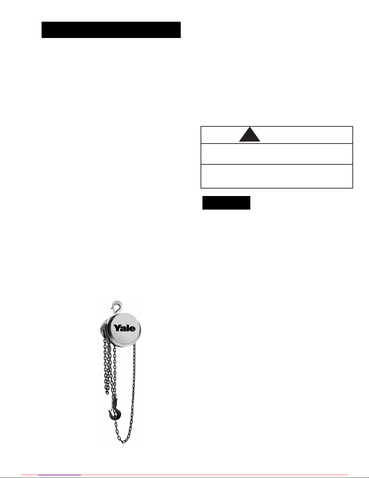
Yale LH2 Hand Hoists
The Yale LH2 Hand Hoist is a highly versatile
tool that can be used to lift loads. The hoist has
aluminum frame, handwheel, handwheel cover
and gear cover to provide dependable strength
at minimum weight. The internal gears are made
of high grade, heat treated steel. Shielded ball
bearings are used at each rotating point in the
mechanism. Latch type, heat treated, forged steel
upper and lower hooks are standard. The load chain
is strong and durable Hoistaloy
®
. A pawl and ratchet,
dry-operating, Weston-type friction brake supplies
very positive load control and will suspend the load
at any point. A Load Limiter is provided on every unit.
As a result, the application of an excessive overload
disengages the driving handwheel and prevents
hoisting. Note that the Load Limiter is not intended
for use as a scaling device. Removal of the excess
load automatically restores normal hoisting action
(see Figure 1 for specifications of available models).
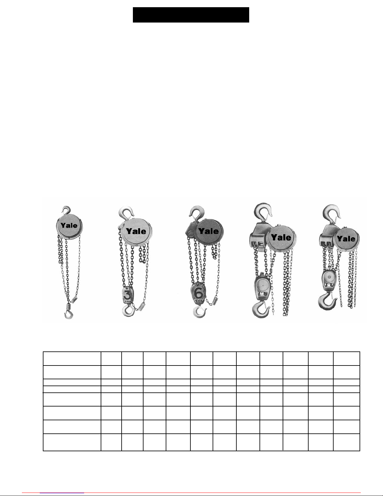
Yale Low Headroom Trolley Hoists
The Yale Low Headroom Trolley Hoists (Figure 2, page 2)
are a combination of the Yale Hand Hoist built
integral with a rugged trolley to provide better headroom than that obtained with the standard hoist and
trolley. The basic hoist is similar to the Yale LH2 Hand
Hoist except the frame, aluminum on the 1/2 through
3 ton units and cast iron on the 4 through 6 ton units,
which is designed to provide low headroom and
attachment to the trolley. The trolley has a rugged
frame, cast iron on the 1/2 through 1 ton units, and
steel plates on the 1-1/2 through 6 ton units. Crowned
tread, flanged trackwheels are provided to minimize
rolling friction. Hardened, pressed steel ball bearing
wheels are used on the 1/2 and 1 ton units. Hardened,
cast iron wheels with Timken bearings are used on the
1-1/2 through 6 ton units. Trolleys are adjustable for
operation on various American standard beams and
the 1-1/2 through 6 ton units are available in a geared
type trolley.
Figure 1. Yale Hand Hoist, Available Models
Maximum
Capacity (Tons)
Code
Standard Lift (Ft.)
Net Weight (Lbs.)
Shipping Weight
(Lbs.)
Shortest Distance
Between Hooks (In.)
Chain Overhauled to
Lift Load 1 Foot (Ft.)
Chain Pull to
Lift Full Load (Lbs.)
1/4
924-
02100
8
33
35
12-7/8
22-1/2
23
1/2
924-
03100
8
33
35
12-7/8
22-1/2
46
1-1/2
924-
06100
8
59
63
17-5/16
40-1/2
80
1
924-
05100
8
36
38
14
30
69
2
924-
07100
8
60
64
17-5/16
52
83
4
924-
11100
8
91
98
21-1/2
104
88
3
924-
09100
8
84
91
21-1/2
81
85
5
924-
13100
8
122
129
24-1/4
156
75
6
924-
14100
8
127
134
25-1/4
156
90
8
924-
16100
8
207
237
35-1/2
208
89
10
924-
17100
8
219
244
35-1/2
260
95
1
1/4 to 2 Ton
3 & 4 Ton
5 & 6 Ton
8 Ton
10 Ton
For more information contact: Sievert Crane and Hoist, (708) 771-1600, parts@sievertelectric.com, www.sievertcrane.com
Page 6
UNPACKING INFORMATION
After removing the hoist from the carton, check to
be sure there has been no damage in shipment.
Before cutting the cord ties on multiple-reeved
units, be sure that all strands of chain are straight
with no twist (due to a capsized hook block). If
length of lift is to be modified, follow disassembly
and assembly instructions for correct procedure.
OPERATING INSTRUCTIONS
After mounting and before placing in service,
check the hoist for proper operation. On multireeved units, be sure that all strands of chain are
straight with no twist (due to a capsized hook
block).
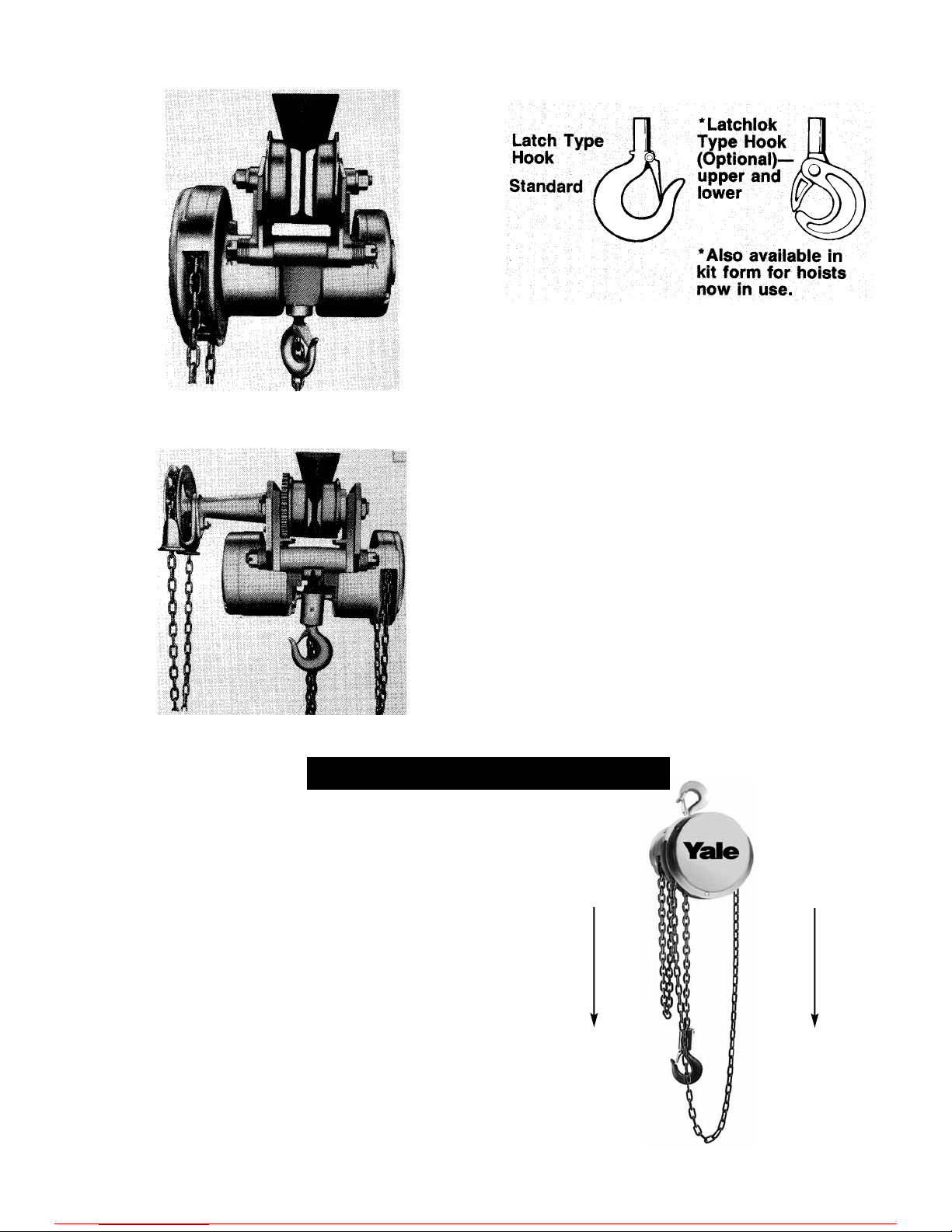
The Yale Hand Hoist must always be rigged to lift
in a straight line from hook to hook (see Figure 4).
The hoist must always be free to swivel on the
upper hook. Under no condition should the hoist
be allowed to bear on any support when in use as
this would cause bending of the hook or frame
and damage the unit.
HOOKS
Type of hooks supplied on the Yale Hoists are shown
in Figure 3.
YALE REPAIR/REPLACEMENT POLICY
All Yale LH2 Hand Hoists and Low Headroom Trolley
Hoists are thoroughly inspected and performance
tested prior to shipment. If any properly maintained
Yale Hoist develops a performance problem due to a
material or workmanship defect, as verified by Yale or
an authorized service station, repair or replacement
of the unit will be made to the original purchaser
without charge. This repair/replacement policy applies
only to Yale Hoists installed, maintained and operated
as outlined in this manual, and specifically excludes
parts subject to normal wear, abuse, improper installation, improper or inadequate maintenance, hostile
environmental effects, and unauthorized repairs/
modifications.
We reserve the right to change materials or design if
in our opinion, such changes will improve our product.
Abuse, repair by an unauthorized person, or use of
non-Yale replacement parts voids the guarantee and
could lead to dangerous operation. For full Terms of
Sale, see Sales Order Acknowledgement. Also, refer to
the back cover for Limitations of Warranties, Remedies
and Damages and, Indemnification and Safe Operation.
2
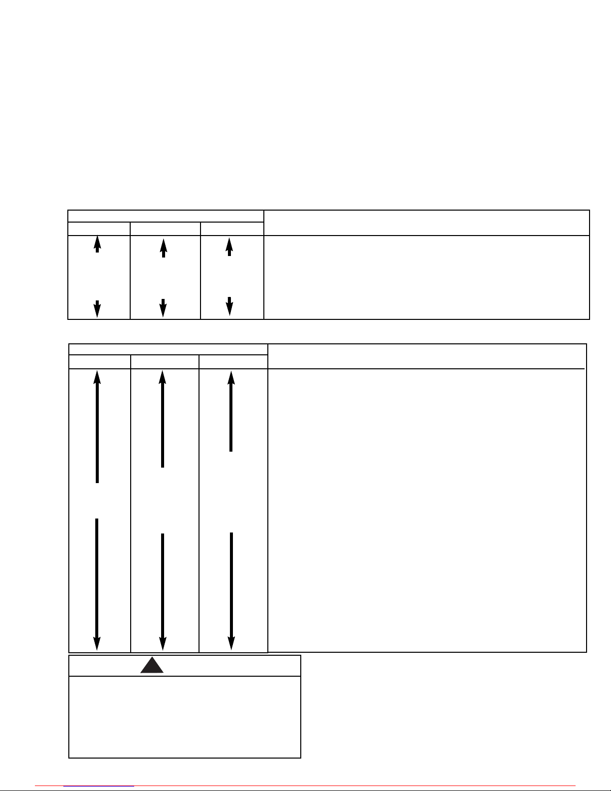
To Lower Hook
Pull on This
Part of
Hand Chain
To Raise Hook
Pull on This
Part of
Hand Chain
Figure 4. Raising and Lowering Hook
Figure 2.
Yale Low Headroom Trolley Hoists
OPERATION AND INSTALLATION
With Geared Trolley
With Plain Trolley
For more information contact: Sievert Crane and Hoist, (708) 771-1600, parts@sievertelectric.com, www.sievertcrane.com
Page 7
TROLLEY INSTALLATION
Operating the trolley hoist on a beam that has no rail
stops may allow the trolley hoist to fall off the end of
the beam.
To Avoid Injury:
Install rail stops at each end of the beam on which
the trolley hoist is to operate.
The railstops must be positioned so as to not exert
impact force on the hoist portion of the unit or the
trolley wheels. They must contact the ends of the
trolley side frames.
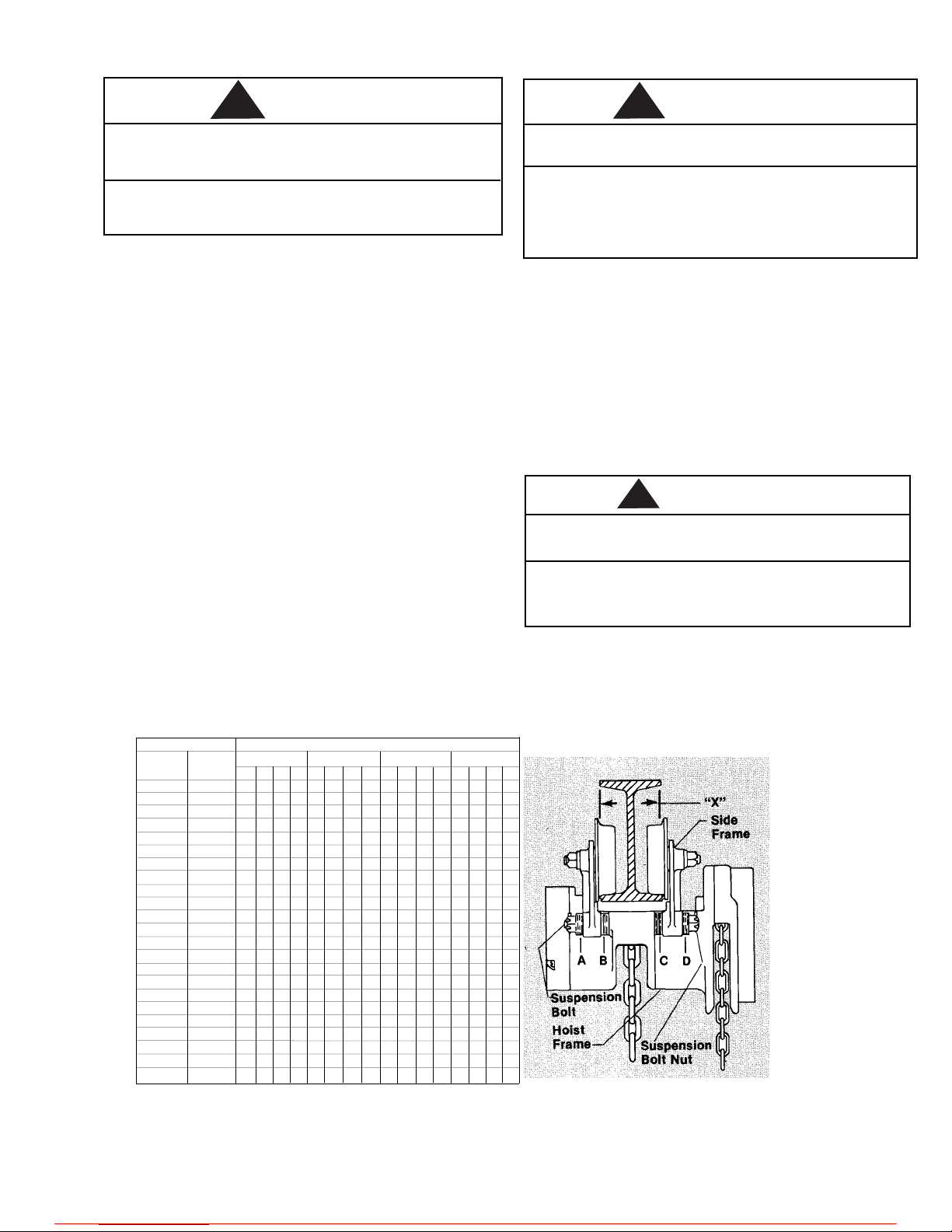
Due to the variations in beam flange widths, it is suggested that the beam flange width be measured to
determine the exact distribution of spacer washers.
The distance between trackwheel flanges (dimension
“X”) should be 1/8 to 3/16 inch greater than the
beam flange width for straight runway beams, and
3/16 to 1/4 inch greater than the beam flange width
if runway system includes sharp curves. Also, the use
of other than Yale supplied washers may result in
trackwheel to beam flange variations and thus Figure
5 will not apply.
Assemble the trolley on the beam by sliding one side
out far enough to allow the wheels to clear the
beam flange. Draw side frames together and tighten
nuts securely (do not over tighten) and then install
the cotter pins.
If washer spacing recommendations are not followed,
trolley hoist may fall from beam.
To Avoid Injury:
Measure the actual beam flange on which the trolley
hoist is to operate and use figure 5 to determine the
arrangement of the spacer washers for that flange
width.
Immediately after installation, operate trolley with a
capacity load over the entire length of runway or
monorail system to be sure that all adjustments and
operations are satisfactory.
When applying a load, it should be directly under
the trolley. Avoid off center loading of any kind.
Side loading may spread trolley side frames.
On systems with curves, the edges of the rail at the
curved sections should be lightly lubricated with
grease.
An excessively worn beam flange may fail and
allow the trolley hoist to fall from the beam.
To Avoid Injury:
Periodically inspect the beam flange for wear.
Replace beam if flange is worn.
3
WARNING
4”x 7.7
4”x 9.5
5”x 10.0
5”x 14.7
6”x 12.5
6”x 17.2
7”x 15.3
7”x 20.0
8”x 18.4
8”x 23.0
10”x 25.4
10”x 35.0
12”x 31.8
12”x 35.0
12”x 40.8
12”x 50.0
15”x 42.9
15”x 50.0
18”x 54.7
18”x 70.0
20”x 65.4
20”x 75.0
24”x 79.9
2-5/8
2-3/4
3
3-1/4
3-3/8
3-5/8
3-5/8
3-7/8
4
4-1/8
4-5/8
5
5
5-1/8
5-1/4
5-1/2
5-1/2
5-5/8
6
6-1/4
6-1/4
6-3/8
7
S-Beam
Number of Spacers
Size
Flange 1/2-1 Ton 1 1/2-2 Ton
3 Ton 4-5-6 Ton
A
4
4
2
0
10
9
8
7
6
5
2
0
0
B
0
0
2
4
0
1
2
3
4
5
8
10
10
C
0
1
2
3
0
2
2
3
4
5
8
10
10
D
4
3
2
1
10
8
8
7
6
5
2
0
0
A
13
12
11
10
9
8
5
3
3
3
2
0
0
B
0
1
0
1
2
3
6
8
8
8
9
11
11
C
0
1
0
1
2
3
6
8
8
9
10
11
11
D
13
12
11
10
9
8
5
3
3
2
1
0
0
A
11
10
9
8
5
3
3
3
2
0
0
B
0
1
2
3
6
8
8
8
9
11
11
C
0
1
2
3
6
8
8
9
10
11
11
D
11
10
9
8
5
3
3
2
1
0
0
A
18
17
14
12
12
12
11
9
9
8
6
4
4
3
0
B
0
1
4
6
6
6
7
9
9
10
12
14
14
15
18
C
0
1
4
6
6
7
8
9
9
10
12
13
13
14
18
D
18
17
14
12
12
11
10
9
9
8
6
5
5
4
0
FIGURE 5. Low Headroom Trolley Spacer Arrangement
WARNING
WARNING
!
!
!
For more information contact: Sievert Crane and Hoist, (708) 771-1600, parts@sievertelectric.com, www.sievertcrane.com
Page 8
OPERATING AND SAFETY PROCEDURES
For safety precautions and a list of do’s and do not’s
for safe operation of hoists, refer to page ii.
The Yale LH2 Hand Hoist (see Figure 6) must always
be rigged to lift in a straight line from hook to
hook. The hoist must always be free to swivel on
the upper hook. Under no condition should the
hoist frame or hanger be allowed to bear on any
support when in use as this would cause bending of
the hook or frame and damage the unit.
When preparing to lift or move a load, be sure that
the attachments to both hooks are firmly seated in
the saddles of the hooks. Avoid off center loading
of any kind especially loading on the point of the
hook.
When lifting, raise the load only enough to clear
the floor or support, and check to be sure brake will
hold load and that attachments to the load are
firmly seated. Continue the lift only after you are
assured the load is free of all obstructions.
Do not load beyond the rated capacity of the hoist.
Overloading can cause immediate failure of some
load carrying part or result in damage causing failure at less than rated capacity. When in doubt, use
the next larger capacity of Yale LH2 Hoist.
Do not wrap load chain around the load or bring
the load in contact with the hoist. Doing this will
result in the loss of the swivel effect of the hook
which could cause twisted chain and a jammed liftwheel. The chain could be damaged at the hook.
Rail stops must be installed for all trolleys operating
on open end beams. These stops must be positioned
to exert impact force on the trolley side frames only.
Do not use this or any other overhead materials
handling equipment for lifting persons.
Stand clear of all loads and avoid moving a load over
the heads of any people. Warn any people of your
intention to move a load in their area.
Do not leave the load suspended in the air unattended.
Do not lower the hook to a point where the chain
becomes taut between the liftwheel and loose end
screw. (See Troubleshooting, Item 5C).
The Yale LH2 Hand Hoist and Yale Low Headroom
Trolley Hoist have been designed for manual
operation only.
Power operation may result in structural damage or
premature wear that may cause a part to break and
allow the load to fall.
To Avoid Injury:
Operate Yale LH2 Hand and Trolley Hoists using
hand power only.
To maintain continuous and satisfactory operation, a
regular inspection procedure must be initiated to
replace worn or damaged parts before they become
unsafe. Inspection intervals must be determined by
the individual application and are based on the type
of service to which your hoist will be subjected and
the degree of exposure to wear, deterioration or
malfunction of the critical components.
The type of service to which the hoist is subjected
can be classified as “Normal”, “Heavy” and “Severe”.
Normal Service: involves operation with randomly
distributed loads within the rated load limit, or
uniform loads less than 65% of rated load for not
more then 25% of the time.
Heavy Service: involves operating the hoist within
rated load limit which exceeds normal service.
Severe Service: is normal or heavy service with
abnormal operating conditions.
Following are the recommended, minimum intervals
of inspection. When the unit is subjected to extra
heavy usage or dusty, gritty, moist, or other adverse
atmospheric conditions, shorter time intervals must
be assigned. During the Periodic Inspection, inspection
must be made of all parts for unusual wear, corrosion
effect or damage in addition to those specifically
mentioned.
Before working on the hoist, review the disassembly
and assembly information on pages 8 through 13.
INSPECTION
FIGURE 6. Yale LH2 Hand
4
WARNING
!
For more information contact: Sievert Crane and Hoist, (708) 771-1600, parts@sievertelectric.com, www.sievertcrane.com
Page 9
Minimum Inspection Schedule
Frequent Inspections: These inspections are
visual examinations by the operator or other designated personnel. Records of such inspections are
not required. The frequent inspections are to be
performed monthly for normal service, weekly to
monthly for heavy service, and daily to weekly for
severe service and they should include those items
listed in Table 1.
Periodic Inspections: These inspections are visual inspections of external conditions by an appointed person. Records of periodic inspections are to
be kept to provide the basis for continuing evaluation of the condition of the hoist.
Periodic inspections are to be performed yearly for
normal service, semi-annually for heavy service and
quarterly for severe service and they are to include
those items listed in Table 2.
Any parts that are deemed unserviceable are to be
replaced with new parts before the unit is returned
to service. It is very important that the unserviceable
parts be destroyed and properly disposed of to
prevent their possible future use as a repair item.
TYPE OF SERVICE
Normal Heavy Severe
TYPE OF SERVICE
Normal Heavy Severe
ITEM
a) Brake for evidence of slippage.
b) Hooks for damage, cracks or excessive throat opening, latch
engagement and latch operation - see page 6.
c) Inspect load chain for adequate lubrication, signs of wear,
damaged links or foreign matter - see page 6.
d) Inspect reeving of the load chain to make sure it is proper -
see page 6.
ITEM
a) Frequent inspections per Table 1.
b) External evidence of loose bolts or nuts.
c) External evidence of worn, corroded, cracked or distorted hook
blocks, suspension bolts, gears, pins, bearings, hand chain wheel,
frames, hoist hanger, load chain guide, hook block pin on 1/4
thru 2 ton units, dead end pin on 3, 4, 8 and 10 ton units, and
dead end screw on 5 and 6 ton units.
d) External evidence of damage to hooks, hook nuts or collars and
hook nut or collar pins.
e) External evidence of damage or excessive wear of the pockets of
the liftwheel, handwheel, hook block sheaves and hanger sheaves.
f) External evidence of worn, glazed or oil contaminated friction
discs, scoring of handwheel hub, ratchet, and friction hub.
g) External evidence of worn pawl and ratchet teeth; corroded,
stretched or broken pawl spring.
h) Supporting structure and trolley, if used, for continued ability to
support the imposed loads.
i) Inspect trolley wheels for external wear on the tread and flange,
and for wear on the internal bearing as evidenced by looseness
on the stud.
j) Warning label and tube for absence or illegibility.
k) Check for proper connections at dead end and loose end of load
chain.
l) Load Limiter components for corrosion.
Monthly
Weekly
to
Monthly
Daily
to Weekly
Table 1 Minimum Frequency Inspections
Table 2 Minimum Periodic Inspections
Yearly
Twice a Year
Every 3 Months
Any deficiencies are to be corrected before returning the
hoist to service. Operating a hoist with worn or damaged
parts or a malfunctioning hoist may result in serious
personal injury to the operator, nearby personnel and/or
property damage.
Also, the external conditions may show the need for disassembly to permit a more detailed inspection which, in
turn, may require the use of nondestructive type testing.
PREVENTIVE MAINTENANCE
In addition to the above inspection procedure, a preventive
maintenance program should be established to prolong
the useful life of the hoist and maintain its reliability and
continued safe use. The program should include the
periodic inspections with particular attention being paid
to the lubrication of various components using the
recommended lubricants.
5
WARNING
!
For more information contact: Sievert Crane and Hoist, (708) 771-1600, parts@sievertelectric.com, www.sievertcrane.com
Page 10
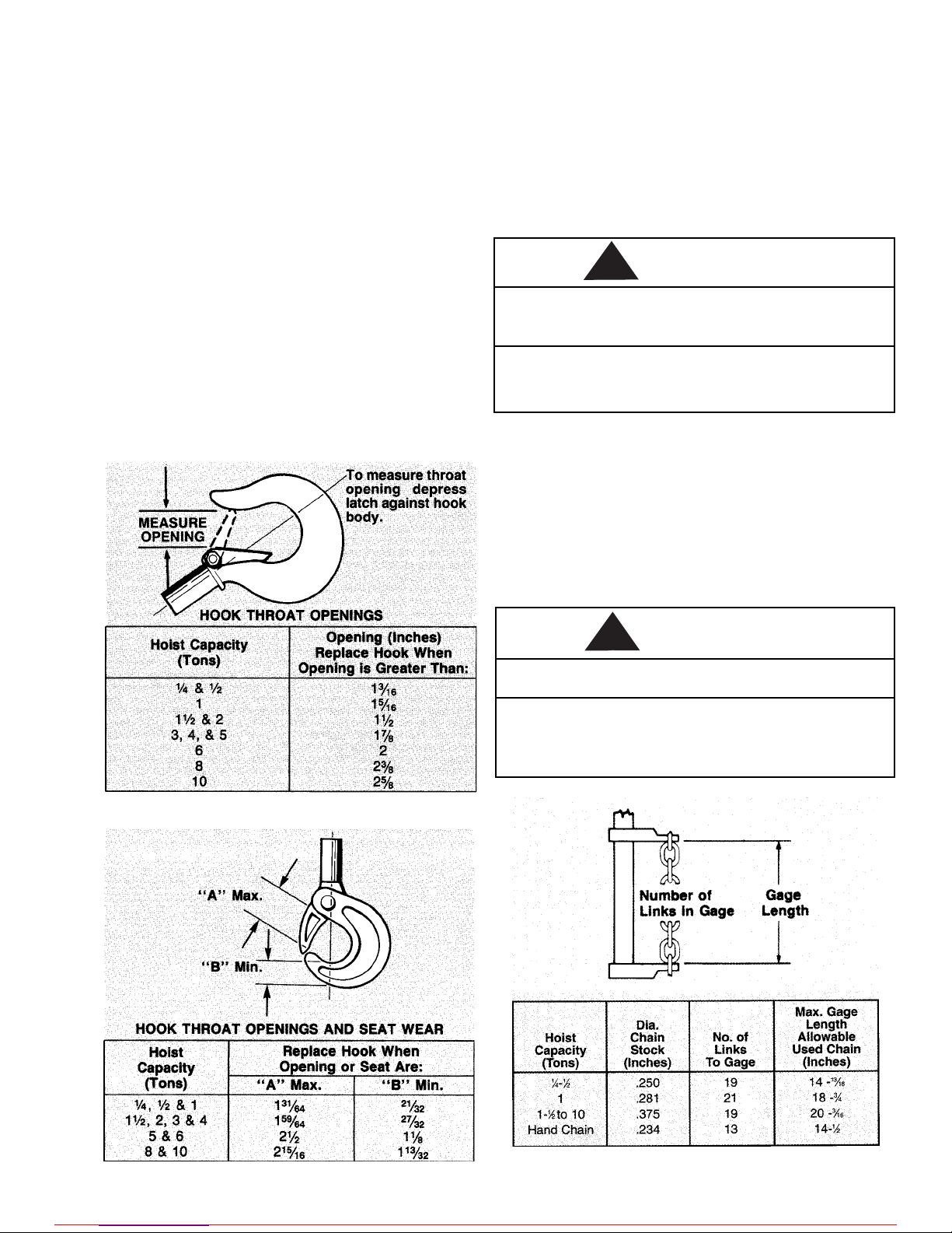
HOOK INSPECTION
Hooks damaged from chemicals, deformation or
cracks, or that have more than a 10 degree twist
from the plane of the unbent hook or excessive
opening or seat wear must be replaced.
Also, on latch type hooks, hooks that are opened
and allow the latch to disengage the tip, must be
replaced.
Any hook that is twisted or has excessive throat
opening indicates abuse or overloading of the unit.
Other load sustaining components of the hoist
should be inspected for damage.
Check to assure latch is not damaged or bent and
that it operates properly with sufficient spring
pressure to keep the latch tightly against the tip of
the hook and allow the latch to spring back to the
tip when released. If the latch does not operate
properly, it should be replaced.
The charts below (Figures 7 and 8) should be used
to determine when the hook must be replaced.
LOAD CHAIN
Cleaning and Inspection
First clean the load chain with a non-acid or non-caustic
type solvent, then slack the chain and make a link-by-link
inspection for nicks, gouges, twisted links and excessive
wear or stretching. Worn chain should be gaged throughout its entire length and replaced if beyond serviceable
limits. Also, these chains are specially heat treated and
hardened and should never be repaired.
Using other than a Yale supplied load chain may
cause the chain to jam and this, in turn may break
the chain and allow the load to drop.
To Avoid Injury:
Use only Hoistaloy®load chain in the Yale LH2 Hand
and Low Headroom Trolley Hoists.
Gaging Load Chain Wear
To determine if the load chain should be continued in
service, check gage lengths as indicated in Figure 9.
Chain worn beyond length indicated, nicked, gouged
or twisted should be replaced before returning the
hoist to service. Chain should be clean, free of twists
and pulled taut before measuring. To aid in checking
gage length, Yale can provide a chain gage. This can
be obtained by ordering chain gage part number 3191.
Worn load chain may break suddenly without visual
deformation.
To Avoid Injury:
Never use load chain for any other purposes such as
slings or tow chains. Cut worn chain into short
lengths to eliminate use after disposal.
FIGURE 7. Latch Hook Opening
FIGURE 8. Latchlok Hook Opening
FIGURE 9. Gaging Load Chain Wear
6
WARNING
WARNING
!
!
For more information contact: Sievert Crane and Hoist, (708) 771-1600, parts@sievertelectric.com, www.sievertcrane.com
Page 11

Note that worn chain can be an indication of
worn hoist components. For this reason, the
hoists chain guide, hook blocks and liftwheel
should be examined for wear and replaced as
necessary when replacing worn chain.
The proper installation of the load chain is
covered in the section on reeving, (see Pages
10 through 13.
HAND CHAIN
Hand chain should be cleaned, inspected and gaged in
the same manner as load chain. It is not hardened and
can be cut with a hacksaw.
The hoist hand chain contains one unwelded connecting
link. This link can be placed in a vise and twisted open
to facilitate changing chain length. Additional connecting
links can be made by cutting the weld side of a standard
link.
Care must be taken to assure that there is no twist in
the hand chain loop.
MAINTENANCE
LUBRICATION
The lubricants used in and recommended for the
Yale LH2 Hand and Trolley Hoists may contain hazardous materials that mandate specific handling and
disposal procedures.
To Avoid Contact and Contamination:
Handle and dispose of lubricants only as directed
in applicable material safety data sheets and in
accordance with applicable local, state and federal
regulations.
NOTE: To assure extra long life and top performance, be sure to lubricate the various
parts of the Yale Hoist using the lubricants
specified below. If desired, these lubricants
may be purchased from Yale. Refer to page 18
for information on ordering the lubricants.
LOAD CHAIN
Lubricate chain with a light coat of Lubriplate®, Bar
and Chain Oil (Fiske Bros. Refining Co.) or equal
lubricant. Be sure the lubricant reaches the bearing
surface between the links. Remove excess oil from
the chain.
Used motor oils contain known carcinogenic materials.
To Avoid Health Problems:
Never use used motor oils as a chain lubricant.
Only use Lubriplate
®
Bar and Chain Oil 10-R as a
lubricant for the load chain.
The hoist normally requires no additional lubrication except when a unit has been disassembled for cleaning or repairs (see page 8).
NOTE: The brake is designed to operate dry.
Do not use any grease or lubricant on the
braking surfaces. On reassembly when
lubricating parts adjacent to the brake, do
not use an excessive amount of lubricant
which could seep onto the brake surfaces.
Load Limiter. Place a small amount of stay-put lubri-
cant such as Moly-Duolube Style 69 (Hercules Packing
Co.) on load limiter handwheel threads. Do not allow
lubricant to contact brake surfaces or friction surfaces
of load limiter.
Gears. Lubricate the gears with Texaco Novatex #2 or
equal, 3 ounces for the 1/4-1 ton units and 4 ounces for
the 1-1/2-10 ton units. Spread some grease on gear
teeth, place the balance in gear housing in contact
with the gears.
Geared Trolleys. Upon installation and once a month
lubricate trackwheel gears and pinion with Texaco
Novatex #2 or an equivalent heavy cup grease or
graphite grease.
Brake. The brake parts should be thoroughly cleaned
(by wiping with a cloth - not by washing with a
solvent) and inspected for wear or scoring. The friction
surfaces of the handwheel, ratchet and friction hub
must be smooth and free from any score marks. When
friction washers are visibly worn to a thickness of 0.100
inches or less, scored excessively, or coated with foreign
matter, replace with new washers. Keep washers and
brake surfaces clean and dry.
RECOMMENDED SPARE PARTS. Refer to page 19 for
the list of recommended spare parts.
EXTERIOR FINISH
The exterior surfaces of the hoist and trolleys have a
durable, scratch resistant baked powder coating.
Normally, the exterior surfaces can be cleaned by
wiping with a cloth. However, if the finish is damaged,
compatible touch-up paint can be purchased from Yale.
Refer to page 18 for information on ordering
the paint.
7
WARNING
WARNING
!
!
For more information contact: Sievert Crane and Hoist, (708) 771-1600, parts@sievertelectric.com, www.sievertcrane.com
Page 12

DISASSEMBLY
Care must be exercised in disassembly of the
hoist to assure proper assembly. The following
pins have tapered splines and can only be
removed by tapping on the end opposite the
splined grooves.
Lower Hook Block, Upper Hook Collar
and Dead End Pins
When removing or installing the Lower Hook
Block Pins (646-29J or 646-129J) on the 1/4 thru
2 ton units, the Upper Collar Pins (646-1E or 646101E) on the 1/4 thru 2 ton units and the Dead
End Pins (646-259) on the 3, 4, 8 and 10 ton units,
care must be taken so as to prevent damaging
the pin and/or the part into which the pin is driven.
These pins are tapered groove pins and as a
result, they can only be removed and installed in
one direction. To remove the pin, a drift and
hammer (or slow acting press) are required. For
the lower hook block pins, a V-block will also be
necessary. The drift should be the same diameter
as the pin (5/16” diameter for the 1/4 thru 1 ton
units and 7/16” diameter for the 1-1/2, 2, 3, 4, 8
and 10 ton units) and it should be placed on the
small end of the pin. The small end of the pin is
the end opposite the end on which the 3 grooves
are visible. Place the drift on the small end of
the pin and drive the pin out using a hammer or
slow acting press. When removing the pin from
the lower hook block, the hook block should be
placed in a V-block.
To re-install the pin, the parts must be arranged
the same as they were when the pin was
removed. To do this, use the small end of the pin
as a gauge. After it is determined which end of
the hole is the largest, arrange the parts so that
the large holes are aligned and insert the small
end of the pin into the hole. Push the pin in by
hand until it stops and then use a hammer or
slow acting press to drive the pin into position
so that the end of the pin is flush with the
outside surface of the hook block body, upper
hook collar or hoist hanger.
Using other than the Yale supplied, high
strength pins may cause the pin to break and
allow the hoist and/or load to fall.
To Avoid Injury:
Use only the special high strength pin as
supplied by Yale.
ASSEMBLY
Consideration must be given to the following
when assembling the hoist:
Brake. Assemble the brake components per Figure 10.
Check the ratchet to be sure the bushing is flush with
or below the surface on both sides. When installed, the
teeth must face as shown in Figure 10 and engage the
pawl. Do not lubricate. The brake operates dry.
FIGURE 10. Brake Assembly
Load Limiter. Place a small amount of stay-put lubricant such as Moly-Duolube Style 69 (Hercules Packing
Co.) on Load Limiter handwheel threads to lubricate
the friction hub at assembly. Do not allow lubricant to
contact brake surfaces or friction surfaces of Load
Limiter.
The handwheel shaft nut and washer must tighten
against the friction hub, not the Load Limiter (see
Figure 11). the Load Limiter must be free to revolve
slightly on the friction hub. If the Load Limiter is
disassembled, it must be recalibrated before being
placed in service.
FIGURE 11. Load Limiter Assembly
8
WARNING
!
For more information contact: Sievert Crane and Hoist, (708) 771-1600, parts@sievertelectric.com, www.sievertcrane.com
Page 13

Components must be assembled in the order
shown with the friction washers seated on the
handwheel projections. Handwheel, spring washer, lockwasher and nut must face as shown.
Tighten the adjuster nut hand tight, then turn
clockwise one notch. A NOTCH is turning the nut
sufficient to bring a slot in the nut and a tang of
the lockwasher in line. The next notch brings a
different slot and tang in line.
Do not bend the lockwasher tang at this time.
The Load Limiter
must be calibrated
after assembly.
Calibration. Install
the Load Limiter
(see Figure 11) and
hand chain but not
the handwheel
cover. Mount the
hoist where a load
greater than that
shown in Table 3
can be applied.
Connect a straight
spring scale to the
hand chain so that
a pull can be
applied in the
hoisting direction.
FIGURE 12. Load Limiter Calibration
Table 3 Minimum Hoist Loads & Pull
Hoist
Capacity
(Tons)
1/4
1/2
1
1-1/2
2
3
4
5
6
8
10
Minimum
Load
(Pounds)
650
1,300
2,600
3,900
5,200
7,800
10,400
13,000
15,600
20,800
26,000
Average Pull
To Slip Load Limiter
(Pounds)
33
67
100
113
117
118
121
106
127
133
139
With the load chain taut, apply a steady pull to
the scale to slip the handwheel one revolution
(approx. 2 ft. of hand chain travel - see Figure
12). Record several pull values and obtain the
average. Disregard the initial “break free” pull use only values obtained after the handwheel has
started to slip. When properly adjusted, the
average pull should be as indicated in Table 3.
If the average pull is low, turn the adjuster nut
one notch clockwise and repeat the pull operation. Do this until the correct value is obtained,
then bend the lockwasher tang into the locknut
notch. Load Limiter is now ready for service.
If the handwheel does not slip or the pull is too
high, back off the adjuster nut and start over.
After the proper calibration is obtained, install
the handwheel cover.
Bearing Retainer Screws. Whenever the bearing
retainer screws have been removed and replaced,
they must be locked in place by prick punching the
head (see Figure 13). Always use new spots for locking.
FIGURE 13. Bearing Retainer Screw
Hoist Hanger. The Hoist Hanger and Hoist are not
bolted together to form a rigid unit but can move
relative to each other.
When installing a new hoist hanger screw (646-234A),
tighten the screw firmly and back off one flat (1/6
turn). Then:
3 and 4 ton hoists: Install hoist hanger set screw
(646-233B).
5 to 10 ton hoists: Using the hole in the end of the
hoist hanger as a guide, drill a 0.250 to 0.256 inch
diameter hole through the hoist hanger screw and the
other side of the hoist hanger. Complete the assembly
by driving the hoist hanger screw pin (646-234D) into
hole so that the end of the pin is flush with the end of
the hoist hanger (see Figure 14).
FIGURE 14. Hoist Hanger
9
For more information contact: Sievert Crane and Hoist, (708) 771-1600, parts@sievertelectric.com, www.sievertcrane.com
Page 14

Hooks. Both upper and lower hooks must be free
to swivel. Those that are held by nuts must be
adjusted to provide 1/32” clearance as shown in
Figure 15 before the hook nut pin is inserted.
FIGURE 15. Hook Mounting
Lower Hook Thrust Bearings. The 1/4 thru 6
ton lower hook thrust bearings are mounted with
the outer shell down (see Figure 15).
Hand Chain. Hand chain must have an odd
number of links.
Join the ends with the “hand chain connecting
link”(646-45) so that there is no twist in the
completed chain loop. The connecting link must
be completely closed so that it will seat in the
handwheel the same as the welded links.
REEVING
Improper installation (reeving) of the load
chain can result in a dropped load.
To Avoid Injury:
Reeve and attach the ends of the load in
accordance with the following instructions.
1/4-1/2-1 Ton Hoists
Attach approximately 20 inches of wire to the
loose end of the load chain. Feed the wire around
the liftwheel as shown in Figure 16 until the first
link starts over it. The first and third links must
stand on edge with the weld away from the liftwheel. After the chain has been started, pull the
hand chain or turn the handwheel in the hoisting
direction until about 2 feet of load chain has
passed over the liftwheel.
If it becomes difficult to pull the hand chain in
the hoisting direction, pull it in the lowering
direction to release the load chain. Start over. This
will prevent the load chain from being jammed
between the liftwheel and frame.
Remove the wire and attach the loose end of
chain to the hoist using the loose end screw and
washer (see Figure 16). The chain must not be
twisted between the liftwheel and loose end screw.
10
FIGURE 16. Reeving ⁄-fi-1 Ton Hoists
Mount hoist in a vertical position and check that the
lower hook is on the same side of the liftwheel as the
upper hook and in line with it.
1-1/2-2 Ton Hoists
Attach approximately 20 inches of wire to the loose
end of the load chain. Feed the wire around the liftwheel as shown in Figure 17 until the first link starts
over it. The first link must lay flat on the liftwheel.
The second link must stand on edge with the weld
away from the liftwheel. After the chain has been
started, pull the hand chain or turn the handwheel in
the hoisting direction until about 2 feet of load chain
has passed over the liftwheel.
If it become difficult to pull the hand chain in the
hoisting direction, pull it in the lowering direction to
release the load chain. Start over. This will prevent the
load chain from being jammed between the liftwheel
and frame.
Remove the wire and attach the loose end of chain to
the hoist using the loose end screw, washer and lockwasher (see Figure 17). The chain must not be twisted
between the liftwheel and loose end screw.
Mount hoist in a vertical position and check that the
lower hook is on the same side of the liftwheel as the
upper hook and in line with it.
WARNING
!
For more information contact: Sievert Crane and Hoist, (708) 771-1600, parts@sievertelectric.com, www.sievertcrane.com
Page 15

3-4 Ton Hoists
Load chain must have an even number of links.
Check at each stage of assembly to be sure chain
has no twist.
Attach approximately 20 inches of wire to one end
of the load chain. Feed the wire around the liftwheel as shown in Figure 17 until the first link starts
over it. The first link must lay flat on the liftwheel.
The second link must stand on edge with the weld
end away from the liftwheel. After the chain has
been started, pull the hand chain or turn the handwheel in the hoisting direction until about 2 feet of
load chain has passed over the liftwheel.
If it becomes difficult to pull the hand chain in
the hoisting direction, pull it in the lowering
direction to release the load chain. Start over.
This will prevent the load chain from being
jammed between the liftwheel and frame.
Remove the wire and attach the loose end of
chain to the hoist using the loose end screw,
washer and lockwasher (see Figure 17).
Mount hoist in a vertical position. Operate in
the hoisting direction until the remaining load
end of chain is approximately 5 feet long. Reeve
load end of chain as shown in Figure 18 in the
following sequence.
1. Down around the lower hook block sheave.
2. Up the the hoist hanger.
Secure chain end to hoist hanger with dead end
pin. The first link around the hook block sheave
must stand on edge (be upstanding).
FIGURE 17. Reeving 1fi-10 Ton Hoists
FIGURE 18. Reeving 3-4 Ton Hoists
5-6 Ton Hoists
Load chain must have an even number of links. Check
at each stage of assembly to be sure chain has no twist.
Attach approximately 20 inches of wire to one end of
the load chain. Feed the wire around the liftwheel as
shown in Figure 17 until the first link starts over it. The
first link must lay flat on the liftwheel. The second link
must stand on edge with the weld away from the liftwheel. After the chain has been started, pull the hand
chain or turn the handwheel in the hoisting direction
until about 2 feet of load chain has passed over the
liftwheel.
If it becomes difficult to pull the hand chain in the
hoisting direction, pull it in the lowering direction to
release the load chain. Start over. This will prevent the
load chain from being jammed between the liftwheel
and frame.
Remove the wire and attach the loose end of chain
to the hoist using the loose end screw, washer and
lockwasher (see Figure 17).
Mount hoist in a vertical position. Operate in the
hoisting direction until the remaining load end of chain
is approximately 10 feet long. Reeve load end of chain
as shown in Figure 19 in the following sequence.
1. Down around the lower hook block sheave.
2. Up around the hoist hanger sheave.
3. Down the lower hook block.
11
Dead End Pin
Loose End of Chain
Hand Chain omitted
for clarity
For more information contact: Sievert Crane and Hoist, (708) 771-1600, parts@sievertelectric.com, www.sievertcrane.com
Page 16

Place end of chain in slot in top of hook block
and secure in place with hook block screw, lockwasher and nut. The first link around the hook
block and hanger sheaves must stand on edge
(be upstanding).
FIGURE 19. Reeving 5-6 Ton Hoists
8 Ton Hoists
Load chain must have an even number of links.
Check at each stage of assembly to be sure chain
has no twist.
Attach approximately 20 inches of wire to one
end of the load chain. Feed the wire around the
liftwheel as shown in Figure 17 until the first link
starts over it. The first link must lay flat on the
liftwheel. The second link must stand on edge
with the weld away from the liftwheel. After the
chain has been started, pull the hand chain or
turn the handwheel in the hoisting direction
until about 2 feet of load chain has passed over
the liftwheel.
If it becomes difficult to pull the hand chain in
the hoisting direction, pull it in the lowering
direction to release the load chain. Start over.
This will prevent the load chain from being
jammed between the liftwheel and frame.
Remove the wire and attach the loose end of
chain to the hoist using the loose end screw,
washer and lockwasher (see Figure 17).
Mount hoist in a vertical position. Operate in the
hoisting direction until the remaining load end
of chain is approximately 15 feet long.
Reeve load end of chain as shown in Figure 20 in the
following sequence.
1. Down around the lower hook block sheave.
2. Up around the hoist hanger sheave.
3. Down around the second hook block sheave.
4. Up the the hoist hanger.
Secure end of chain to the chain anchor with the dead
end pin. The first link around the hook block sheaves
must stand on edge and the first link around the hoist
hanger sheave must lay flat.
Loose End of Chain
Hand Chain omitted
for clarity
FIGURE 20. Reeving 8 Ton Hoists
10 Ton Hoists
Load chain must have an odd number of links. Check at
each stage of assembly to be sure chain has no twist.
Attach approximately 20 inches of wire to one end of
the load chain. Feed the wire around the liftwheel as
shown in Figure 17 until the first link starts over it. The
first link must lay flat on the liftwheel. The second link
must stand on edge with the weld away from the liftwheel. After the chain has been started, pull the hand
chain or turn the handwheel in the hoisting direction
until about 2 feet of load chain has passed over the liftwheel.
If it becomes difficult to pull the hand chain in the hoisting direction, pull it in the lowering direction to release
the load chain. Start over. This will prevent the load
chain from being jammed between the liftwheel and
frame.
Remove the wire and attach the loose end of chain to
the hoist using the loose end screw, washer and lockwasher (see Figure 17).
12
Hand Chain omitted
for clarity
Loose End of Chain
Dead End Pin in
Chain Anchor
For more information contact: Sievert Crane and Hoist, (708) 771-1600, parts@sievertelectric.com, www.sievertcrane.com
Page 17

FIGURE 21. Reeving 10 Ton Hoists
Mount hoist in a vertical position. Operate in the
hoisting direction until the remaining load end
of chain is approximately 20 feet long. Reeve
load end of chain as shown in Figure 21 in the
following sequence.
1. Down around the lower hook block sheave.
2. Up around the hoist hanger sheave.
3. Down around the second hook block sheave.
4. Up around the second hoist hanger sheave.
5. Down to the lower hook block.
Secure end of chain to the hook block with the
dead end pin. The first link around the hook block
sheaves must lay flat and the first link around the
hoist hanger sheaves must stand on edge.
Cutting Chains
Hoistaloy®load chain is hardened for wear
resistance and is difficult to cut. However, the
following methods are recommended when
cutting a length of new chain from stock or cutting
off a length of worn chain.
FIGURE 22. Cutting Chain by Nicking
(1) Use a grinder and nick the link on both sides
(see Figure 22), then secure the link in a vise
and break off with a hammer.
(2) Use a 7 inch minimum diameter by 1/8 thick
abrasive wheel (of type recommended by wheel
supplier) that will clear adjacent links.
(3) Chain may also be cut using a bolt cutter (see
Figure 23) similar to the H.K. Porter No. 0590MTC
with special cutter jaws for cutting hardened
chain (1 inch long cutting edge).
FIGURE 23. Cutting Chain with a Bolt Cutter
Cutting chain can produce flying particle.
To Avoid Injury:
• Wear eye protection.
• Provide a shield, such as a heavy rag, over the chain
to prevent flying particles.
TESTING
Prior to initial use, all altered or repaired hoists or used
hoists that have not been operated for the previous 12
months shall be tested by the user for proper operation.
Test the unit first in the unloaded state and then with
a light load of 50 pounds times the number load supporting parts of load chain to be sure it operates properly and the brake holds the load when the hand chain
is released; then test with a load of
*
125% of rated
capacity by or under the direction of an appointed person and a written report prepared for record purposes.
After this test, the function of the Load Limiter is to be
tested (see Table 3, page 9).
*
If load limiter prevents lifting of a load of 125% of rated capacity, reduce load
to rated capacity.
NOTE: For additional information on inspection
and testing, refer to the current issue of ASME
B30.16 “Overhead Hoists” obtainable from ASME
Order Department, 22 Law Drive, Box 2300,
Fairfield, NJ 07007-2300, U.S.A.
Yale
13
WARNING
!
For more information contact: Sievert Crane and Hoist, (708) 771-1600, parts@sievertelectric.com, www.sievertcrane.com
Page 18

14
TROUBLESHOOTING
For disassembly and assembly follow instructions on pages 8 through 13. Always test the Yale LH2 Hoists under
load after reassembly of any parts to be sure it operates properly and holds the load when the hand chain is
released.
PROBLEM
1 Hoist is hard to
operate in either
direction.
2. Hoist is hard to
operate in the
lowering direction.
3. Hoist is hard to
operate in the hoisting
direction.
4) Hoist will not operate
in either direction.
5) Hoist will not operate in
the lowering direction.
6. Hoist will not operate
in the hoisting direction.
7. Hoist will not hold load
in suspension.
CAUSE MAY BE
A) Load chain worn long to gage, thus
binding between liftwheel and chain guide.
B) Load chain rusty, corroded or clogged up
with foreign matter such as cement or
mud.
C) Load chain damaged.
D) Liftwheel clogged with foreign matter or
worn excessively, causing binding between
the liftwheel and chain guide.
E) Hand chain worn long to gage, thus
binding between handwheel and cover.
F) Handwheel clogged with foreign mater or worn.
G) Liftwheel or gear teeth deformed.
A) Brake parts corroded or coated with
foreign matter.
B) Chain binding.
A) Chain binding.
B) Chain twisted. (3 ton capacity or larger).
C) Overload.
A) Liftwheel gear key or friction hub key
missing or sheared.
B) Gears jammed.
A) Locked brake due to a suddenly applied
load, shock load, or load removed by
means other than by operating unit in
the lowering direction.
B) Chain binding.
C) Lower hook all the way out. Load chain
fully extended.
A) Chain binding.
A) Lower hook or load side of chain on
wrong side of liftwheel.
B) Ratchet assembled in reverse.
C) Pawl not engaging with ratchet.
D) Ratchet teeth or pawl worn or broken.
E) Worn brake parts.
F) Oily, dirty or corroded brake friction surfaces.
REMEDY
A) Check gage of chain (see Page 6). Replace
if worn excessively.
B) Clean by tumble polishing or using a non-
acid or non-caustic type solvent. Lubricate
with Lubriplate
®
Bar and Chain Oil 10-R
(Fiske Bros. Refining Co.) or equal lubricant.
C) Check chain for gouges, nicks, bent or
twisted links. Replace if damaged.
D) Clean out pockets. Replace if worn
excessively.
E) Check gage of chain (see Page 6).
F) Clean out pockets. Replace if worn excessively.
G) Excessive overload has been applied.
Replace damaged parts.
A) Disassemble brake and clean thoroughly.
(By wiping with a cloth - not by washing
in a solvent). Replace washers if gummy,
visibly worn or coated with a foreign
matter. Keep washers and brake surfaces
clean and dry.
B) See Items 1A, 1B and 1C.
A) See Items 1A, 1B and 1C.
B) Rereeve chain on 3 and 4 ton unit, if both
chains are twisted, capsize hook block
through loop in chain until twists are
removed. Caution - do not operate unit in
hoisting direction with twisted chain or
serious damage will result.
C) Reduce load or use correct capacity hoist.
A) Install or replace key.
B) Inspect for foreign matter in gear teeth.
A) With hoist under load keep chain taut,
pull sharply on hand chain in the lowering
direction to loosen brake.
B) See Items 1A, 1B and 1C.
C) Chain taut between the liftwheel and loose end
screw. Operate unit in hoisting direction only.
A) See Items 1A, 1B and 1C.
A) Lower hook must be on same side of lifwheel
as upper hook.
B) Ratchet must be assembled as shown in Figure 10.
C) Pawl spring missing or broken. Pawl binding on
pawl stud. Replace spring and clean so pawl
operates freely and engages properly with
ratchet. Do not oil.
D) Replace pawl and/or ratchet.
E) Replace brake parts which are worn.
For more information contact: Sievert Crane and Hoist, (708) 771-1600, parts@sievertelectric.com, www.sievertcrane.com
Page 19

15
PARTS LIST
ORDERING INFORMATION
The following information must accompany all
correspondence or repair parts orders.
1) Hoist capacity.
2) Serial Number - this is stamped on the hoist
frames as shown below.
Using “Commercial” or other manufacturer’s parts to
repair the Yale LH2 Hand and Low Headroom Trolley
Hoists may cause load loss.
To Avoid Injury:
Order all replacement parts from Yale. Parts may
look alike but often Yale parts are made of specific
materials or processed to achieve specific properties.
For parts orders also specify:
1) Quantity desired.
2) Key number of part.
3) Part name.
4) Part number.
When ordering replacement parts, consideration
should be given to the need to replace other items:
bearings, fasteners, gaskets, etc. Items that may be
damaged or lost during disassembly or just unfit for
future use because of deterioration from age or service.
Parts should be ordered from Yale’s Authorized Parts
Depots conveniently located throughout the United
States. Refer to page i of this manual to locate the
parts depot nearest you.
WARNING
I.D. Label
646-276
I.D. Label
646-276
!
For more information contact: Sievert Crane and Hoist, (708) 771-1600, parts@sievertelectric.com, www.sievertcrane.com
Page 20

Key
No.
646-1
646-1A
646-1B
646-1B
646-1C
646-1D
646-1E
646-1F
646-2A
646-2B
646-2C
646-3A
646-3B
646-3C
646-4
646-4A
646-4B
646-4C
646-4D
646-5
646-5A
646-6
646-7
646-8
646-9
646-9A
646-9B
646-9CD
646-9D
646-10
646-11
646-12
646-13
646-14
646-14A
646-15
646-15A
646-16
646-16A
646-16B
646-16C
646-16D
646-17A
646-17B
646-18
646-19
646-20
646-24
646-24A
646-24B
646-24C
646-24D
646-25A
646-25B
646-29
646-29A
646-29A
646-29B
646-29D
646-29E
646-29F
646-29G
646-29H
646-29J
646-30
646-31
646-32
646-38
646-45
646-101
646-101A
No.
Req’d
1
1
1
1
2
1
1
1
1
2
2
1
3
1
1
1
1
1
1
1
1
1
1
1
1
1
1
2
1
1
1
1
1
1
1
1
1
3
1
1
1
1
1
1
1
2
1
1
1
1
1
2
3
1
1
1
1
1
1
1
1
1
1
1
1
1
1
1
1
2
1
1
1
Part Name
Frame with Upper Hook (includes Items 646-1A
thru 646-1F and 646-15) - Not Shown
Frame
Upper Hook (Includes Latch) - Latch Type
Upper Hook - Latchlok Type
Upper Hook Washer
Upper Hook Collar
Upper Hook Collar Pin
Upper Hook Sleeve
Load Chain Guide
Load Chain Guide Screw
Load Chain Guide Screw L.W.
Stripper
Stripper Screw
Stripper Screw L.W.
Handwheel Shaft and Pinion with Bearings (Items
646-4A thru 646-4D - Not Shown)
Handwheel Shaft and Pinion
Pinion Shaft Bearing (Handwheel End)
Pinion Shaft Bearing (Gear End)
Handwheel Shaft Snap Ring
Pawl
Pawl Bushing
Pawl Retaining Washer
Pawl Stud Snap Ring
Pawl Spring
Brake Assembly (Items 646-9A, 646-9B and 6469CD) - Not Shown
Friction Hub
Friction Washer
Ratchet with Bushing
Ratchet Bushing
Non-Load Limiter Handwheel
Handwheel Shaft Nut Washer
Handwheel Shaft Nut
Friction Hub Key
Handwheel Cover
Cover Label
Operating Instruction Label (See Page 16) - Not Shown
Handwheel Cover Screw
Liftwheel with Bearings (Items 646-16A thru 646-16D)
- Not Shown
Liftwheel
Liftwheel Bearing (Handwheel End)
Liftwheel Bearing (Gear End)
Liftwheel Snap Ring
Frame Bearing Retainer
Frame Bearing Retainer Screw
Liftwheel Gear
Liftwheel Gear Key
Liftwheel Gear Snap Ring
Gear Cover with Capacity Insert
Capacity Insert
Capacity Insert Pin
Gear Cover Screw
Gear Cover Gasket
Loose End Screw
Loose End Screw Washer
Lower Hook and Block Assembly-Latch Type Hook
Lower Hook with Latch-Latch Type Hook
Lower Hook-Latchlok Type Hook
Hook Block Body
Lower Hook Washer
Lower Hook Thrust Bearing
Lower Hook Nut
Lower Hook Nut Pin
Lower Hook Chain Block
Hook Block Pin
Load Chain (Specify Lift or Length Req’d)
Hand Chain (Specify Lift or Length Req’d)
Warning Tube
Latch Kit
Hand Chain Connecting Link
Frame with Upper Hook (Includes Items 646-101A
thru 646-101E and 646-15) - Not Shown
Frame
Capacity - Ton
1/4 & 1/2 1 1-1/2 & 2 3 & 4 5 & 6 8 & 10
Part Number
C701Y C702Y --
45612Y --
45601Y 45602Y --
1020 1022 --
45930 -41350 27359 -45940 45941 -45390 -- -45047 45048 --
945807 --
945851 --
45043 -983745 -940830 --
C703 C704 --
45353 45354 --
88437 -88444 -45873 --
45038
45735
45910
45767
45730
C705
45007
45741 For Units With Load Limiter, 45831 For Units Without Load Limiter
45614
45718
46699
45915
931717
45770
46236
46200
946900
982698
C706 C707 --
45364 45365 --
88489 -88429 -45871 -45750 --
987716 --
45061 45060 --
989101 --
68703 --
C708Y for 1/4 Ton, C721Y for 1/2 Ton and C722Y for 1 Ton
46705 (1/4 Ton) --
46706 (1/2 Ton) --
46707 (1 Ton) --
988271
987322 --
45747 -946801 -954807 --
28683 45668 --
28686 35611
1051 --
45401 -945921 --
88485 -982526
983772 --
28007 45016 --
45943 --
85839 85841 --
85808
946735
45661 45662 --
945490
-- C730Y --
-- 45613Y
16
YALE LH2 HAND HOIST PARTS LIST
For more information contact: Sievert Crane and Hoist, (708) 771-1600, parts@sievertelectric.com, www.sievertcrane.com
Page 21

Key
No.
646-101B
646-101B
646-101C
646-101D
646-101E
646-102A
646-102B
646-102C
646-103A
646-103B
646-104
646-104A
646-104B
646-104C
646-116
646-116A
646-116B
646-116C
646-116D
646-116E
646-118
646-119
646-121
646-121A
646-121B
646-121C
646-122
646-124
646-124A
646-124B
646-124C
646-124D
646-125A
646-125B
646-125C
646-129
646-129A
646-129A
646-129B
646-129E
646-129F
646-129G
646-129H
646-129J
646-130
646-131
646-132
646-133
646-134
646-135
646-136
646-137
646-138
646-139
646-144
646-201B
646-201B
646-201C
646-201E
646-201F
646-206
646-229
646-229A
646-229A
No.
Req’d
1
1
2
1
1
1
3
3
1
2
1
1
1
1
1
1
1
1
1
1
1
2
1
1
1
1
2
1
1
2
3
1
1
1
1
1
1
1
1
1
1
1
1
1
1
1
1
1
1
2
1
1
1
1
2
1
1
2
1
1
2
1
1
1
Part Name
Upper Hook (Includes Latch) Latch Type
Upper Hook-Latchlok Type
Upper Hook Washer
Upper Hook Collar
Upper Hook Collar Pin
Load Chain Guide
Load Chain Guide Screw
Load Chain Guide Screw L.W.
Stripper
Stripper Screw
Handwheel Shaft and Pinion with Bearings (Items
646-104A, 646-104B and 646-104C) - Not Shown
Handwheel Shaft and Pinion
Handwheel Shaft Bearing (Handwheel End)
Handwheel Shaft Bearing (Pinion End)
Liftwheel with Bearings (Items 646-116A thru
646-116E) - Not Shown
Liftwheel
Liftwheel Bearing (Handwheel End)
Liftwheel Bearing (Gear End)
Liftwheel Snap Ring
Liftwheel Bearing Retaining Ring (Gear End)
Liftwheel Gear
Liftwheel Dowel Pin
Intermediate Gear and Pinion with Bearings (Items
646-121A, 646-121B and 646-121C) - Not Shown
Intermediate Gear & Pinion
Intermediate Gear Bearing (Pinion End)
Intermediate Gear Bearing (Cover End)
Gear Cover Dowel
Gear Cover with Capacity Insert
Capacity Insert
Capacity Insert Pin
Gear Cover Screw
Gear Cover Gasket
Loose End Screw
Loose End Screw L.W.
Loose End Screw Washer
Lower Hook and Block Assembly-Latch Type Hook
Lower Hook with Latch-Latch Type Hook
Lower Hook-Latchlok Type Hook
Hook Block Body
Lower Hook Thrust Bearing
Lower Hook Nut
Lower Hook Nut Pin
Lower Hook Chain Block
Hook Block Pin
Load Chain (Specify Lift or Length Req’d)
Hand Chain (Specify Lift or Length Req’d)
Load Limiter Complete
Handwheel Sub-Assembly
Load Limiter Hub
Friction Washer
Steel Washer
Spring Washer
Lockwasher
Nut
Latch Kit
Upper Hook (Includes Latch)-Latch Type
Upper Hook-Latchlok Type
Upper Hook Washer
Upper Hook Nut Pin
Upper Hook Nut
Latch Kit
Lower Hook Block Assembly - Not Shown
Lower Hook (Includes Latch)-Latch Type
Lower Hook-Latchlok Type
Capacity - Ton
1/4 & 1/2 1 1-1/2 & 2 3 & 4 5 & 6 8 & 10
Part Number
-- 45604Y --
-- 1023 --
-- 45918 --
-- 35478 --
-- 45946 --
-- 45049
-- 945815
-- 45852
-- 45420
-- 982709
-- C710 For 1-1/2 & 3 Ton, C711
-- For 2, 4, 5, 6, 8 & 10 Ton
--
45355 for 1-1/2 & 3 Ton, 45356 for 2, 4 , 5, 6, 8 & 10 Ton
-- 88437
-- 83671
-C712
-- 45057
-- 88445
-- 83669
-- 45766
-- 46800
-- 45008
-- 45771
C713 for 1-1/2 & 3 Ton, C714 for 2, 4, 5, 6, 8 & 10 Ton
-- 45014 for 1-1/2 & 3 Ton (7 & 45 Teeth)
-- 45015 for 2, 4, 5, 6, 8 & 10 Ton (7 & 47 Teeth)
-- 83682
-- 88437
-- 46730
C715Y for 1-1/2 Ton, C723Y for 2 Ton, C724Y for 3 Ton, C725Y for 4 Ton,
C726Y for 5 Ton, C727Y for 6 Ton, C728Y for 8 Ton & C729Y for 10 Ton
46708 (1-1/2 Ton), 46709 (2 Ton), 46710 (3 Ton)
46711 (4 Ton), 46712 (5 Ton), 46713 (6 Ton),
46714 (8 Ton), 46715 (10 Ton)
-- 988271
-- 983732
-- 46704
-- 945815
-- 945852
-- 954806
-- 45669 --
-- 45603 --
-- 1024 --
-- 45399 --
-- 88505
-- 45382
-- 983779
-- 45017
-- 45948
85839 85864
85808
44602 for 1/4 Ton, 44601 for 1/2 Ton, 44600 for 1 thru 10 Ton
45675
45012
45886
45032
45888
45033
45737
-- 45663 --
-- 45607Y 45606Y (5T.) 45609Y
40607Y (6T.)
-- 1025 1027 1028
-- 40736 988005
-- 983787 983788
-- 940834 945836
-- 45664 45664 (5T.) 45697
45665 (6T.)
46230 for 3 Ton, 46231 for 4 Ton.
46232 for 5 Ton, 46233 for 6 Ton
46234 for 8 & 10Ton
-- 45605 45606 (5T.) 45609
40607 (6T.)
-- 1026 1027 1028
17
YALE LH2 HAND HOIST PARTS LIST
For more information contact: Sievert Crane and Hoist, (708) 771-1600, parts@sievertelectric.com, www.sievertcrane.com
Page 22

Key
No.
646-229B
646-229G
646-229K
646-229L
646-233A
646-233B
646-234A
646-234C
646-234D
646-235
646-236
646-237
646-238
646-239
646-241
646-242
646-243
646-244
646-245
646-246A
646-246B
646-247
646-248
646-249A
646-249B
646-249C
646-250
646-252
646-253
646-254
646-256A
646-256B
646-257
646-258
646-259
646-260
646-275
646-276
No.
Req’d
1
1
1
1
1
1
1
1
1
1
1
1
1
1 or 2
1 or 2
2
1
2
2
1
1
2
1
3
3
3
1 or 2
1 or 2
2
1 or 2
1
1
1
1
1
2
1
1
Part Name
Lower Hook Sleeve
Lower Hook Pin
Lower Hook Nut
Lower Hook Thrust Bearing
Hoist Hanger (Also order 646-234A and 646-234B
or 646-234D as applicable)
Hoist Hanger Set Screw
Hoist Hanger Screw (Also order 646-234B or
646-234D as applicable)
Hoist Hanger Screw Washer
Hoist Hanger Screw Pin
Hoist Hanger Screw Sleeve
Hoist Hanger Sheave Cap (Tapped)
Hoist Hanger Sheave Cap (Drilled)
Hoist Hanger Chain Anchor
Hoist Hanger Sheave
Hoist Hanger Bearing
Hoist Hanger Sheave Bearing
Hoist Hanger Snap Ring
Hoist Hanger Bearing Retainer
Hoist Hanger Sheave Shaft
Hoist Hanger Sheave Shaft Bolt
Hoist Hanger Sheave Shaft Bolt L.W.
Lower Hook Block (Also order Capacity Insert
646-275 for 5 & 6 Ton Units)
Lower Hook Block Body (Also order Capacity
Insert 646-275)
Lower Hook Block Screw
Hook Block Screw Nut
Hook Block Screw L.W.
Hook Block Sheave
Hook Block Sheave Bearing
Hook Block Sheave Bearing
Hook Block Sheave Shaft
Hook Block Sheave Shaft Bolt
Hook Block Sheave Shaft Bolt L.W.
Hook Block Sheave Cap (Tapped)
Hook Block Sheave Cap (Drilled)
Dead End Pin
Reeving Caution Plate
Capacity Insert
I.D. Label
Capacity - Ton
1/4 & 1/2 1 1-1/2 & 2 3 & 4 5 & 6 8 & 10
Part Number
-- 45394 45393 45410
-- 983787 983788
-- 940834 945836
-- 88507 88511
-- 45090Y 45091Y 45094Y
-- 986304 --
-- 987223 987179
-- 945916 --
-- 983789
-- 45391 --
-- 45123Y
-- 45124Y
-- 45134Y (8T.)
-- 45085 45106
-- 88542
-- 83670 --
-- 45765 --
-- 45151 --
-- 45425
-- 89411
-- 987919
45107Y (3T.)
-- 45096Y (4T.) 45101Y --
-- 45104Y
-- 945796 45812 --
-- 945820 945822 --
-- 945851 945853 --
-- 45086 45106
-- 88542
-- 83670 --
-- 45425
-- 89411
-- 987919
-- 45123Y
-- 45124Y
-- 45945 -- 45944
-- 45757 --
46712 for 5 Ton, 46713 for 6 Ton, 45837 for 8 Ton & 45838 for 10 Ton
46211 46210
Part Numbers for packaged lubricants used in
Yale LH2 Hand and Low Headroom Trolley Hoists
Lubricant
Usage
Gears
Handwheel
Threads
Chain
Trackwheel
Bearings
Trackwheel
Gears
Handwheel
Shaft
Type of
Lubricant
Grease
Spray
Oil
Grease
*Heavy Cup
Grease
*Light Machine
Oil
Part Numbers
and Packaged
Quantities of
Lubricants
28610 (1#can)
28632 (4#can)
46698 (16 oz.)
28608 (1 pt. can)
28619 (1 gal. can)
28610 (1#can)
28632 (4#can)
--
--
*These are not furnished by Yale in Packaged Quantities.
When ordering lubricants, specify the type of lubricant, part number and
packaged quantity required.
Touch-up Paints for Yale LH2 Hand and Low Headroom Trolley Hoists:
1. Hoist. Order *(1) case (12-12 oz. Aerosol Cans) of Yellow Touch-up paint
Part Number 40215.
2. Trolley. Order *(1) case (12-12 oz. Aerosol Cans) of Black Touch-up paint
Part Number 84189.
*Touch-up paints are only available in case quantities.
NOTE: When painting hoists or trolleys, also order warning labels,
identification labels, etc. that may be coated during painting.
18
YALE LH2 HAND HOIST PARTS LIST
For more information contact: Sievert Crane and Hoist, (708) 771-1600, parts@sievertelectric.com, www.sievertcrane.com
Page 23

RECOMMENDED SPARE PARTS
Key No.
646-5
646-5A
646-6
646-7
646-8
646-9B
646-24D
646-124D
648-124C
Part Name
Pawl
Pawl Bushing
Pawl Retaining Washer
Pawl Stud Snap Ring
Pawl Spring
Friction Washer
Gear Cover Gasket (1/4, 1/2 & 1 T.)
Gear Cover Gasket (1-1/2 - 10T.)
Gear Cover Gasket (Trolley Hoist)
Qty. for each Hoist in service
1
1
1
1
1
2
1
1
1
To insure continued service of the Yale LH2 Hand and Low Headroom Trolley Hoist, the following is a
list of the parts that are recommended to be kept on hand at all times to replace parts that are worn.
Refer to page 15 for ordering instructions and parts lists for part numbers.
19
NOTES
For more information contact: Sievert Crane and Hoist, (708) 771-1600, parts@sievertelectric.com, www.sievertcrane.com
Page 24

20
For more information contact: Sievert Crane and Hoist, (708) 771-1600, parts@sievertelectric.com, www.sievertcrane.com
Page 25

Yale
21
For more information contact: Sievert Crane and Hoist, (708) 771-1600, parts@sievertelectric.com, www.sievertcrane.com
Page 26

22
For more information contact: Sievert Crane and Hoist, (708) 771-1600, parts@sievertelectric.com, www.sievertcrane.com
Page 27

23
For more information contact: Sievert Crane and Hoist, (708) 771-1600, parts@sievertelectric.com, www.sievertcrane.com
Page 28

24
For more information contact: Sievert Crane and Hoist, (708) 771-1600, parts@sievertelectric.com, www.sievertcrane.com
Page 29

25
YALE LOW HEADROOM TROLLEY HOIST PARTS LIST
Key
No.
648-1
648-2A
648-2B
648-2C
648-3A
648-3B
648-3C
648-3D
648-4A
648-4B
648-4C
648-4D
648-14B
648-15A
648-16A
648-16B
648-16C
648-16D
648-17A
648-17B
648-20
648-24B
648-30
648-31
648-32
648-33
648-34
648-45
648-60
648-60B
648-60C
648-60D
648-61A
648-61B
648-62
648-63A
648-63B
648-63C
648-64
648-65
648-66A
648-66B
648-66C
648-101
648-102A
648-102B
648-102C
648-103A
648-103B
648-103C
648-104A
648-104B
648-104C
648-112
648-115A
648-116A
648-116B
648-116C
648-116D
648-117A
648-117B
648-121D
648-122A
648-122B
648-122C
648-122D
No.
Req’d.
1
1
2
2
1
2
3
1
1
1
1
1
1
3
1
1
1
2
1
2
1
3
1
1
1
1
2
1
1
1
1
1
4
4
2
2
4
4
4
4
4
4
1
1
3
3
1
1
1
1
1
1
2
3
1
1
1
1
1
2
1
1
2
3
3
Part Name
Main Frame
Load Chain Guide
Load Chain Guide Screw
Load Chain Guide Screw L.W.
Stripper
Stripper Screw-Long
Stripper Screw L.W.
Stripper Screw-Short
Handwheel Shaft & Pinion
Handwheel Shaft Bearing (Handwheel End)
Handwheel Shaft Bearing (Gear End)
Handwheel Shaft Snap Ring
Cover Label
Handwheel Cover Screw
Liftwheel
Liftwheel Bearing (Handwheel End)
Liftwheel Bearing (Gear End)
Liftwheel Snap Ring
Frame Bearing Retainer
Frame Bearing Retainer Screws
Liftwheel Shaft Nut
Gear Cover Screw
Load Chain (Specify Lift or Length Req’d.)
Hand Chain (Specify Lift or Length Req’d.)
Warning Tube
I.D. Plate
Drive Screw
Hand Chain Connecting Link
Front Frame with Pawl Stud and Pawl Spring Pin
Pawl Spring Pin
Pawl Stud Pin
Pawl Stud
Front Frame Screw
Front Frame Screw L.W.
Trolley Frame
Suspension Bolt
Suspension Bolt Nut
Suspension Bolt Cotter Pin
Spacer Washer (Specify Quantity)
Trackwheel
Trackwheel Stud
Trackwheel Stud Nut
Trackwheel Stud Nut L.W.
Main Frame
Load Chain Guide
Load Chain Guide Screw
Load Chain Guide Screw L.W.
Stripper
Stripper Screw
Stripper Screw L.W.
Handwheel Shaft and Pinion
Handwheel Shaft Bearing (Handwheel End)
Handwheel Shaft Bearing (Gear End)
Handwheel Shaft Nut
Handwheel Cover Screw
Liftwheel
Liftwheel Bearing (Handwheel End)
Liftwheel Bearing (Gear End)
Liftwheel Snap Ring
Frame Bearing Retainer
Frame Bearing Retainer Screw
Intermediate Gear and Pinion Nut
Spider
Spider Dowel
Spider Attaching Screw
Spider Attaching Screw L.W.
Capacity - Ton
1/2 & 1 1-1/2, 2 & 3 4, 5 & 6
Part Number
48001Y --
45047 (1/2 T.) --
45048 (1T.)
982368 -945851 --
45043 --
982709 --
Order 648-3B & 648-3D --
987315 --
45357 (1/2 T.) --
45358 (1 T.)
88437 -88444 -45873 --
46216
982698 --
48362 (1/2 T.) --
48368 (1 T.)
88429 -83674 -48704 --
48702 -987716 -945841 -987322 --
85839 (1/2 T.) --
85841 (1 T.)
85808 --
946735
46219
988271
945490 -48611Y -983531 -983494 --
48376 -987019 -945851 --
*48005 -*48371 --
948803 -988343 -948700 --
*50762 --
*48300 -*948804 -*987924 --
-- **48010Y for 1-1/2 & 2 Ton, 48010Y for 3 Ton,
48013Y for 4, 5 & 6 Ton
-- 45049
-- 948805
-- 45852
-- 48043
-- 87055
-- 987919
45360 (10 Teeth, 18-7/64 Long) for
-- 1-1/2 & 3 Ton, 45359 (8 Teeth, 18-7/64
Long) for 2 Ton and 45361 (8 Teeth,
20-47/64 Long) for 4, 5 & 6 Ton.
-- 88437
-- 83671
-- 931717
-- 982698
-- 48369 48370
-- 83678
-- 83669
-- 45766
-- 45751
-- 987716
-- 931717
-- 45035
-- 45430
-- 982689
-- 940830
*Part numbers listed are for trolleys that operate on 6” thru 12” S-beams. If trolley operates on 4” or 5” S-beam, part numbers are as follows: 48006 for
648-62 trolley frame, 48373 for 648-63A suspension bolt, 54732 for 648-65 trackwheel, 54731 for 648-66A trackwheel stud, 982521 for 648-66B trackwheel
stud nut and 987921 for 648-66C trackwheel stud nut lockwasher.
**Part number listed is for trolley that operates on 7” thru 15” S-beams. If trolley operates on 6” S-beam, part number is 48032Y (1-1/2 & 2 Ton).
For more information contact: Sievert Crane and Hoist, (708) 771-1600, parts@sievertelectric.com, www.sievertcrane.com
Page 30

YALE LOW HEADROOM TROLLEY HOIST PARTS LIST
Key
No.
648-123A
648-123B
648-124A
648-124B
648-124C
648-130
648-131
648-145
648-160
648-160B
648-160C
648-160D
648-161A
648-161B
648-161C
648-162A
648-162B
648-163A
648-163B
648-163C
648-164
648-165A
648-165B
648-165C
648-165D
648-166A
648-166B
648-166C
648-167
648-168A
648-168B
648-169A
648-169B
648-170
648-171
648-172
648-173
648-174A
648-174B
648-175A
648-175B
648-176
648-177A
648-177B
648-177C
648-177D
648-178A
648-178B
648-178C
648-179
648-180
648-230
648-231
648-232
648-239
648-242
648-243
648-243
648-244
648-260
648-261
648-262
648-263
No.
Req’d.
1
2
1
3
1
1
1
1
1
1
1
1
4
5
1
1
1
2
4
4
-4
8
8
8
4
4
4
1
5
5
2
4
1
1
1
1
1
2
3
3
1
1
1
1
1
1
2
2
1
1
1
2
2
1
2
1
1
2
1
1
1
1
Part Name
Spider Bearing Retainer
Spider Bearing Retainer Screw
Gear Cover
Gear Cover Screw
Gear Cover Gasket
Load Chain (Specify Lift or Length Req’d.)
Hoist Hand Chain (Specify Lift or Length Req’d.)
Hand Chain Connecting Link
Front Frame with Pawl Stud and Pawl Spring Pin
Pawl Spring Pin
Pawl Stud Pin
Pawl Stud
Front Frame Screw
Front Frame Screw L.W.
Front Frame and Stripper Screw
Trolley Frame (Specify if for Plain or Geared)
Trolley Frame (Specify if for Plain or Geared)
Suspension Bolt
Suspension Bolt Nut
Suspension Bolt Cotter Pin
Spacer Washer (Specify Quantity)
Trackwheel
Trackwheel Bearing Cup
Trackwheel Bearing Cone
Trackwheel Bearing Seal Washer
Trackwheel Stud
Trackwheel Stud Nut
Trackwheel Stud Collar
Gear Housing
Gear Housing Screw
Gear Housing Screw L.W.
Trackwheel Gear
Trackwheel Gear Pin
Trackwheel Pinion
Trackwheel Pinion Key
Trolley Handwheel
Trolley Handwheel Key
Handwheel Bracket with Bushings
Handwheel Bracket Bushing
Handwheel Bracket Screw
Handwheel Bracket Screw L.W.
Trolley Hand Chain Guide
Trolley Hand Chain Guide Screw
Trolley Hand Chain Guide Screw Nut
Trolley Hand Chain Guide Screw L.W.
Trolley Hand Chain Guide Screw Washer
Trolley Handwheel Shaft
Trolley Handwheel Shaft Nut
Trolley Handwheel Shaft L.W.
Trolley Hand Chain (Specify Lift or Length Req’d)
Hand Chain Connecting Link
Hanger Chain Anchor Pin (4 Ton)
Hanger Chain Anchor Pin Retainer (4 Ton)
Hanger Chain Anchor Pin Block (4 Ton)
Upper Sheave (5 & 6 Ton)
Upper Sheave Bearing (5 & 6 Ton)
Hanger Snap Ring (4 Ton)
Upper Sheave Bearing Snap Ring (5 & 6 Ton)
Upper Sheave Bearing Retainer (5 & 6 Ton)
Hanger Chain Anchor
Dead End Pin (3 & 4 Ton)
Liftwheel Gear
Intermediate Gear and Pinion
Capacity - Tons
1/2 & 1 1-1/2, 2 & 3 4, 5 & 6
Part Number
-- 45752
-- 987716
-- 45717Y
-- 983732
-- 45746
-- 85864
-- 85808
-- 945490
-- 48612Y
-- 983531
-- 983535
-- 48376
-- 987020
-- 945851
-- 948807 987034
-- 48668 48670
48667 for 1-1/2, 2 & 3 Ton Plain Trolley
46664 for 1-1/2, 2 & 3 Ton Geared Trolley
-- 48669 for 4, 5 & 6 Ton Plain Trolley
46665 for 4, 5 & 6 Ton Geared Trolley
58503 (1” Dia. x 12-1/4” Long) for
-- 1-1/2, 2 and 3 Ton. 48372 (1-1/4 Dia.
x 15”Long) for 4, 5 & 6 Ton
-- 958818 945835
-- 988368 988381
-- 958726 948701
-- 58162 58163
-- 88521 88556
-- 88525 88545
-- 68918 68917
-- 58459 58540
-- 982613 988192
-- 58484 58492
-- 48015Y
-- 948806 948807
-- 945851
-- 58548 58549
-- 983503
-- 46385
-- 85446
-- 33143
-- 59967
-- 59616
-- 58727
-- 987061
-- 945853
-- 58152
-- 987065
-- 945822
-- 945853
-- 986224
-- 58504
-- 988095
-- 986270
-- 85808
-- 945490
-- -- 45425
-- -- 48024
-- -- 48393
-- -- 45085
-- -- 83670
-- -- 45765
-- -- 45765
-- -- 45151
-- 48019Y 48021Y
(3 Ton) (4 Ton)
-- 45945 45944
(3 Ton) (4 Ton)
-- 45062
-- 45080 for 1-1/2 & 3 Ton, 45081 for 2, 4, 5 & 6 Ton
26
For more information contact: Sievert Crane and Hoist, (708) 771-1600, parts@sievertelectric.com, www.sievertcrane.com
Page 31

THE WARRANTY STATED BELOW IS GIVEN IN PLACE OF
ALL OTHER WARRANTIES, EXPRESS OR IMPLIED, OF MER-
CHANTABILITY, FITNESS FOR A PARTICULAR PURPOSE, OR
OTHERWISE, NO PROMISE OR AFFIRMATION OF FACT
MADE BY ANY AGENT OR REPRESENTATIVE OF SELLER
SHALL CONSTITUTE A WARRANTY BY SELLER OR GIVE
RISE TO ANY LIABILITY OR OBLIGATION.
Seller warrants that on the date of delivery to carrier the goods
are free from defects in workmanship and materials.
SELLER’S SOLE OBLIGATION IN THE EVENT OF BREACH
OF WARRANTY OR CONTRACT OR FOR NEGLIGENCE OR
OTHERWISE WITH RESPECT TO GOODS SOLD SHALL BE
EXCLUSIVELY LIMITED TO REPAIR OR REPLACEMENT,
F.O.B. SELLER’S POINT OF SHIPMENT, OF ANY PARTS
WHICH SELLER DETERMINES TO HAVE BEEN DEFECTIVE
or if Seller determines that such repair or replacement is not fea-
sible, to a refund of the purchase price upon return of the goods
to Seller.
Any action against Seller for breach of warranty, negligence or
otherwise, must be commenced within one year after such
cause of action occurs.
NO CLAIM AGAINST SELLER FOR ANY DEFECT IN THE
GOODS SHALL BE VALID OR ENFORCEABLE UNLESS
BUYER’S WRITTEN NOTICE THEREOF IS RECEIVED BY
SELLER WITHIN ONE YEAR FROM THE DATE OF SHIPMENT.
Note: When ordering parts, always furnish hoist model and serial number,
motor horsepower, voltage, phase, frequency and rated capacity of hoist on
which the parts are to be used.
For the location of the nearest Authorized Repair Station, Contact Yale, (see
inside front cover).
LIMITATION OF WARRANTIES, REMEDIES AND DAMAGES
Seller shall not be liable for any damage, injury or loss arising out
of the use of the goods if, prior to such damage, injury or loss,
such goods are (1) damaged or misused following Seller’s delivery
to carrier; (2) not maintained, inspected, or used in compliance
with applicable law and Seller’s written instructions and recommen-
dations; or (3) installed, repaired, altered or modified without com-
pliance with such law, instructions or recommendations.
UNDER NO CIRCUMSTANCES SHALL SELLER BE LIABLE FOR
INCIDENTAL OR CONSEQUENTIAL DAMAGES AS THOSE
TERMS ARE DEFINED IN SECTION 2-715 OF THE UNIFORM
COMMERCIAL CODE.
INDEMNIFICATION AND SAFE OPERATION
Buyer shall comply with and require its employees to comply with
directions set forth in instructions and manuals furnished by Seller
and shall use and require its employees to follow such instructions
and manuals and to use reasonable care in the use and mainte-
nance of the goods. Buyer shall not remove or permit anyone to
remove any warning or instruction signs on the goods. In the event
of personal injury or damage to property or business arising from
the use of the goods, Buyer shall within 48 hours thereafter give
Seller written notice of such injury or damage. Buyer shall cooper-
ate with Seller in investigating any such injury or damage and in
the defense of any claims arising therefrom.
If Buyer fails to comply with this section or if any injury or damage
is caused, in whole or in part, by Buyer’s failure to comply with
applicable federal or state safety requirements, Buyer shall indem-
nify and hold Seller harmless against any claims, loss or expense
for injury or damage arising from the use of the goods.
WARNING
Alterations or modifications of equipment and use of nonfactory repair parts can lead to dangerous operation and
injury.
TO AVOID INJURY:
• Do not alter or modify equipment.
• Do use only factory provided replacement parts.
414 WEST BROADWAY AVENUE
MUSKEGON, MICHIGAN 49443-0769
1-866-805-2962 • Fax: 1-800-742-9270
Printed in USA
5-17-01
2001 Yale Hoist
!
For more information contact: Sievert Crane and Hoist, (708) 771-1600, parts@sievertelectric.com, www.sievertcrane.com
 Loading...