

Page 1
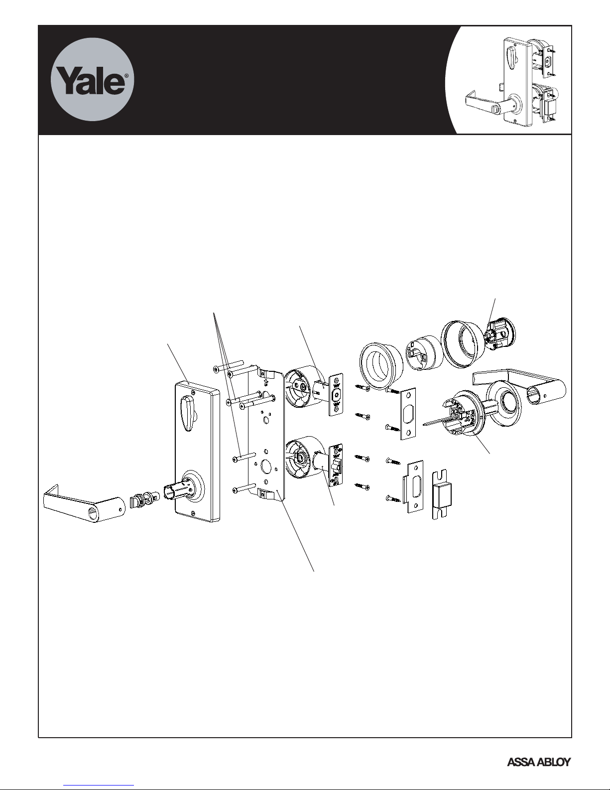
4800LN GRADE 2 INTERCONNECTED LOCKSET
INSTALLATION INSTRUCTIONS
Installation of this product requires that two 2 1/8" holes are spaced 4" apart center to center. See the hole template
sheet for accurate holelocations.
Connecting Screws
Interior Mechanism Housing
Deadbolt Latch
Installation Plate
Latch
Deadbolt
Tailpiece
Hub with Square Spindle
An ASSA ABLOY Group brand
P/N 80-9510-0056-010 Rev B
Page 2
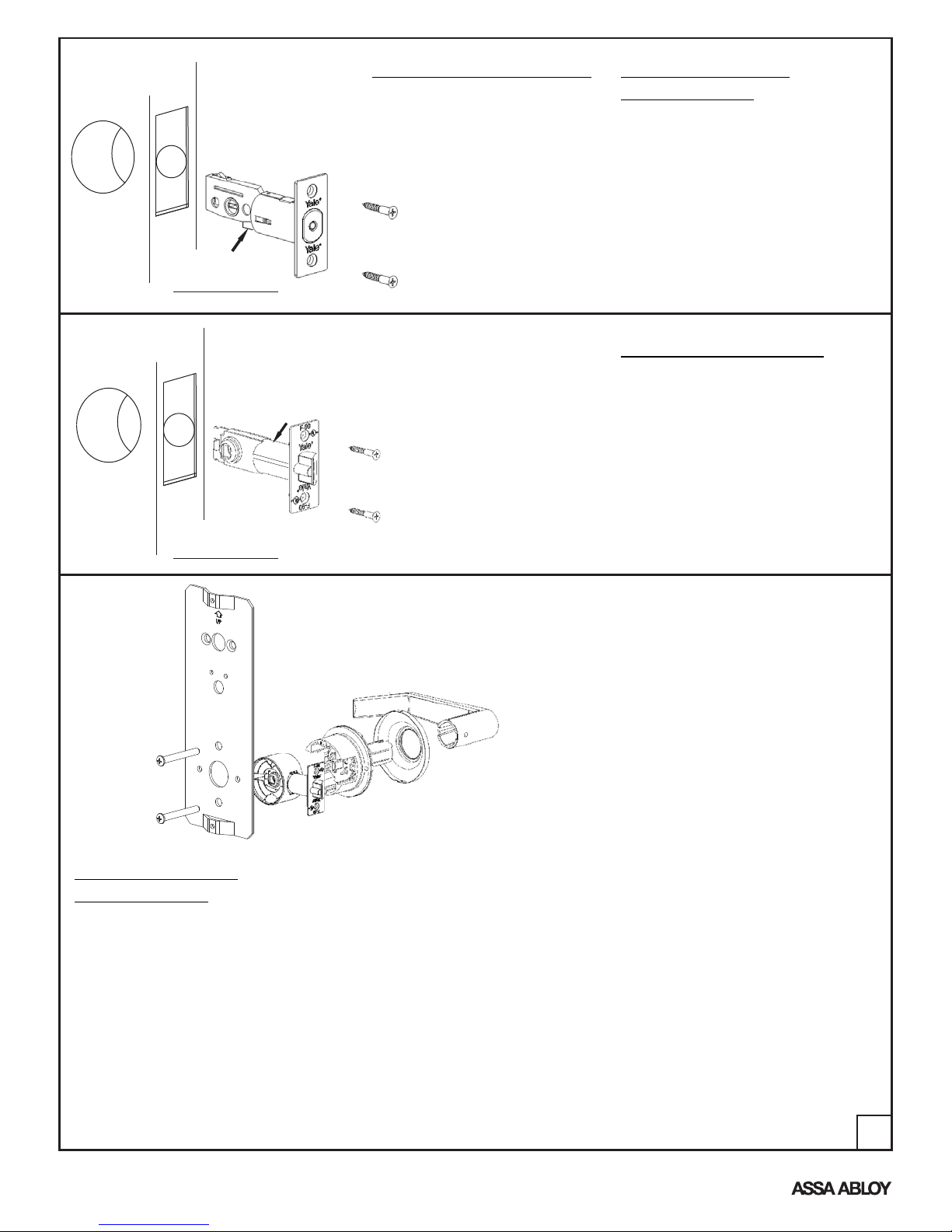
Tab
Deadbolt Fig. 1
Plastic Sleeve
BACKSET ADJUSTMENT
Firmly push and hold tab. Pull
deadbolt apart for 2-3/4"
backset and push together for
2-3/8" backset. Make sure tab
is held in through motion.
DEADBOLT LATCH
INSTALLATION
Insert latch through the hole in the
door edge and screw in place using
two 3/4" Phillips head screws. There
is a rectangular slide cam on the
back side part of the latch This is the
top of the latch. It should be up. DO
NOT INSTALL WITH THIS
POINTING DOWN.
LATCH INSTALLATION
Insert latch with plastic sleeve
through the hole in door edge and
screw in place using two 3/4" Phillips
head screws. Curved edge of latch
bolt should face in direction that door
closes.
Latchbolt Fig. 2
EXTERIOR LEVER
INSTALLATION
Exterior Assembly
There is a spring button on the tube
of the assembly. It should point
away from the door edge toward
the hinge side of the door. For
keyed entry levers, the release
button should point towards the
door’s edge. Insert the square
spindle of the exterior assembly
through the cam of the lower latch
and insert the connecting screws
loosely. Tighten these two screws.
Lever Assembly
Line up the hole in the neck of the
lever with the release button, then
slide the lever until the button
aligns with the hole. Using a key,
nail, or other pointed tool, depress
the button and push the lever onto
the tube until the button snaps into
the hole in the neck of the lever.
Assembly/Verification
Using a key from the exterior,
operate the deadbolt latch to insure
correct alignment. Operate the
exterior lever insuring smooth
operation. If the deadbolt or the
exterior lever does not operate
smoothly, adjust the installation
plate up and down or side to side to
find the correct position then
tighten all four connecting screws.
Interior Mechanism Housing
Reinstall the interior mechanism
housing on the installation plate
with the two self-thread screws
saved before. Once this operation
is done, the square
make sure
spindle for the interior mechanism
housing is inside the hub of the
lower latch and operates the latch.
Note that the thumbturn must be in
the vertical position, then slide the
lever over the bottom tube and
proceed same as with the exterior
assembly.
2
An ASSA ABLOY Group brand
P/N 80-9510-0056-010 Rev B
Page 3

DEADBOLT INSTALLATION
Unscrew the top and bottom screws from the
interior mechanism housing and remove the
installation plate. Save these screws to reinstall
housing on the installation plate.
The exterior deadbolt assembly has a blade
(tailpiece) attached to the rear of the cylinder.
This tailpiece passes through the latch and
engages the interior assembly. Insert the key in
the cylinder so that the flat edge of the key is
down and slide the tailpiece through the
horizontal slot in the latch. Insert the deadbolt
connecting screws through the installation plate
and connect the plate with the exterior deadbolt
housing. Slightly tighten these two screws.
Deadbolt screws are 1/4" x 2-1/2" for 2" to 1-1/2"
thickness doors. Use 1/4" x 2-1/16" screws also
included for 1-3/8" thickness doors. DO NOT
INSTALL WITH THE DEADBOLT EXTENDED.
INTERIOR MECHANISM HOUSING
Reinstall the interior mechanism housing on the
installation plate with the two self-thread screws
saved before. Once this operation is done,
the square spindle for the interior
sure
mechanism housing is inside the hub of the
lower latch and operates the latch. Note that the
thumbturn must be in the vertical position then
slide the lever over the bottom tube and proceed
same as with the exterior assembly.
make
NEW DOOR PREPARATION
1. Fold template as marked and place on door. If
corner of door is beveled, place template on
widest side of door.
2. Mark centers for all holes. Drill 1/8" (3mm) pilot
holes at centers. Drill completely through door
thickness.
3. Bore 2-1/8" (54mm) hole halfway through door.
Finish bore from other side to prevent
splintering.
4. To mark strike location, close the door and push
locator pin through both guide holes marking
the strike plates center position.
5. Bore 2 holes 1" (25mm) through the door edge.
6. For handleset installation only: Bore 5/16" hole
to receive bottom portion of handleset.
7. Insert the latch and then trace outlines of
latchplates. Carefully chisel away outlined areas
until plates fit flush. Drill pilot holes for
latchplates mounting screws.
An ASSA ABLOY Group brand
STRIKE PLATE INSTALLATION
1. To prepare door frame for strike
plates, locate the strike plates'
center position. Marked on the
stage 4 for “new door preparation”.
2. Trace outlines of strike plates.
Carefully chisel away outlined
areas until plates fit flush.
3. With a 1" (25mm) drill bit, drill a 1"
(25mm) deep hole at the upper
strike plate to accept the bolt.
4. With a 1"(25mm) drill bit, drill a
1/2"(13mm) deep hole at the lower
strike plate to accept the latch bolt.
5. Drill pilot holes for the plate
mounting screws.
6. Secure the strike plates with (2)
3/4" screws.
3
P/N 80-9510-0056-010 Rev B
Page 4

REMOVAL OF CYLINDER
When not installed on door
Remove the loose plate from the
back of the cylinder. Two screws
hold a metal strap in place. Under
the “C” cutout in this strap is a
semicircular indention in a spring
loaded tab. Using the cylinder
removing tool (wire with loop) or a
screwdriver, place the tip of the tool
against the tab in the indention and
push toward the center and then
clockwise. The purpose is to move
Dummy Trim
See Interior Mechanism Housing Installation
Page 3 For Installation Instructions
the cylinder and strap to the left.
When all the way left, push the
cylinder out of the housing.
Note: it may be necessary to put
the tool in between the gap created
on the right and force the cylinder
to the left. Remove the plug
assembly from the cylinder housing
for re-keying.
REMOVAL OF CYLINDER
When installed on door
Insert the key into the plug. Press
the
cylinder removing tool into the hole
positioned at 5 o’clock and turn the
key counterclockwise. This will
cause the face of the cylinder to
rotate to the left slightly. Once
turned off center, pull on the key to
remove the cylinder. Remove the
plug assembly from the cylinder
housing for re-keying.
100 Yale Avenue, Lenoir City, TN 37771 • Product Support Tel 800.438.1951 • Fax 800.338.0965 • www.yalecommercial.com
Yale® is a registered trademark of Yale Security Inc., an ASSA ABLOY Group company. Other products' brand names may be trademarks or registered trademarks of their respective
owners and are mentioned for reference purposes only. These materials are protected under U.S. copyright laws. All contents current at time of publication. Yale Security Inc., an ASSA ABLOY Group
company reserves the right to change availability of any item in this catalog, its design, construction, and/or its materials. Copyright © 2006, 2008, Yale Security Inc., an ASSA ABLOY Group company.
An ASSA ABLOY Group brand
All rights reserved. Reproduction in whole or in part without the express written permission of Yale Security Inc. is prohibited.
4
P/N 80-9510-0056-010 Rev B
 Loading...