

Yale 2312BC,2313BC,2314BC,2315BC, 2312BC, 2315BC, 2313BC, 2314BC Installation Instructions Manual
Page 1
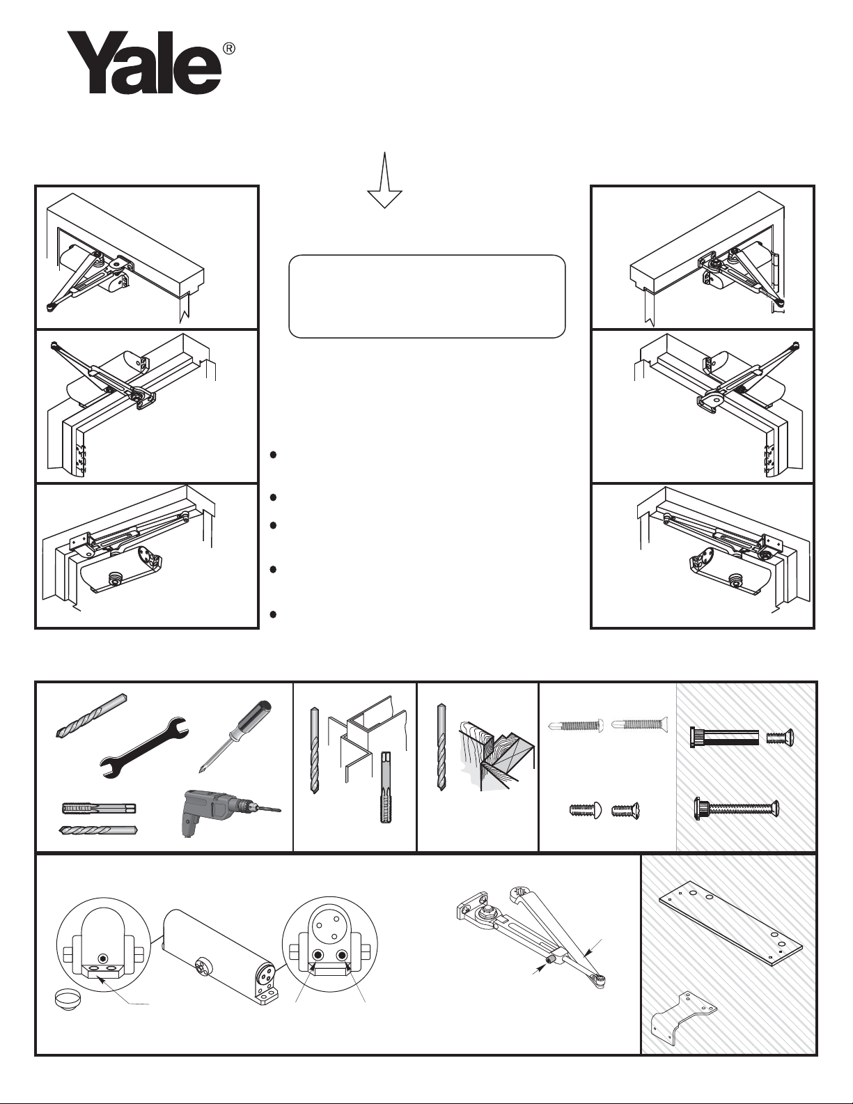
2310BC
Series
Regular Arm
Installation
See Page 2
Installation Instructions
80-9323-0012-010 (01-09)
Hold Open Arm Models
Weaker
-
Stronger
+
Sized
(Sizes 2,3,4,5)
2312BC
2313BC
2314BC
2315BC
Non Handed Door Closer
Regular Arm
Top Jamb
Parallel Arm
Regular Arm
Installation
See Page 2
Right
Hand Door - RH
Left
Hand Reverse - LHR
Left Hand Door - LH
Right Hand Reverse - RHR
Left Hand Door - LH
Right Hand Reverse - RHR
Top Jamb
Installation
See Page 5
Parallel Arm
Installation
See Pages
3 & 4
An Incorrectly installed or improperly adjusted
door closer can cause property damage or
personal injury. These installation instructions
should be followed to avoid the possibility of
misapplication or misadjustment.
CAUTION
CAUTION
NOTE: For special applications a separate
door and frame preparation template is
packed with these instructions. Use this
instruction sheet for installation sequence
and closer adjustments only.
Doors should be hung on ball bearing or
anti-friction hinges.
A separate door stop is recommended.
Door and frame must be properly
reinforced.
Adjust closing time speed between 3 and 7
seconds from 90° to 0°.
These door closers should NOT be
installed on the exposed side (weather
side) of exterior doors.
Left
Right
Top Jamb
Installation
See Page 5
Right Hand Door - RH
Left Hand Reverse - LHR
Parallel Arm
Installation
See Pages
3 & 4
Hand Door - LH
Hand Reverse - RHR
Right Hand Door - RH
Left Hand Reverse - LHR
Pinion Cap
Self Drilling Screws
Wood and Metal
For Wood drill 3/16 hole
Machine Screws
#7
Metal Wood
1/4-20
Standard Components
3/16"
#7 Drill, 1/4-20 Tap
Optional Components
Closer Body
Main Arm
Set
4
Closer
Size
Stamp
"L"Valve
"S"Valve
Screw
Soffit Adapter Plate
Arm
Assembly
(Optional)
Sleeve Nut and Bolt
Drill 9/32 thru from Closer Side
3/8 Drill other side
Thru Bolt and Grommet Nut
Drill 9/32 thru from Closer Side
3/8 Drill other Side
2388
Plate
2588 Soffit Plate
Used with Parallel
Arm Closers Only
Page 2
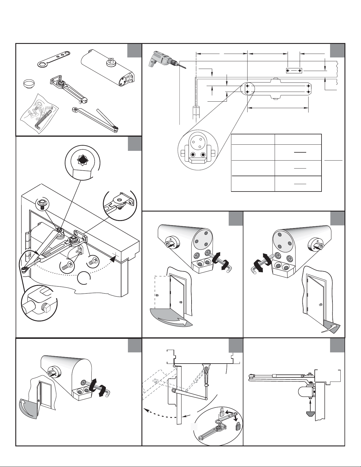
2310BC Series
Hold Open Door Closers — Regular Arm
80-9323-0012-010 (01-09)
Parts
1
1-1/4
(32)
L
3
R
Y
Z
S
C
D
Left
Hand
Nut Down
Sweep
L
A
3/4
(19)
Right Hand Shown
Opening
S
To 100°
101° to 120°
121° to 180°
*
Door/Wall/Hardware/Jamb
*
conditions permitting
4
6
(152)
9-1/16
(230)
Dimension "A"
Latch
7
(178)
6
(152)
3-1/2
(89)
1-3/4
(44)
3
2
7/8
(22)
Inches
(mm)
5
F
Backcheck
Caution:
Don't completely
close valve
L
A
B
90°
BC
E
Stronger
Weaker
-
6
+
Set Hold Open
9
0
°
-
1
8
0
°
A
-
Faster
+
°
0
9
m
7
.
n
i
Slower
S
B
Faster
+
Slower
-
L
Pinion Cap
Screw pinion cap onto
pinion shaft by hand or
with a Phillips screw
driver - DO NOT
OVER TIGHTEN.
S
8
— 2 —
Page 3

2310BC Series
Hold Open Door Closers — Parallel Arm
80-9323-0012-010 (01-09)
Parts
Door
Opening
To 100°
101° to 130°
131° to 180°
*
Door/Wall/Hardware/Jamb
*
conditions permitting
A
9-1/4
(235)
7-3/4
(197)
5-3/4
(146)
Optional
B
7-5/8
(194)
6-1/8
(156)
4-1/8
(105)
2388
Plate
C
8-5/8
(219)
7-1/8
(181)
5-1/8
(130)
1
Right Hand Shown
2-1/8
(54)
Holes for 9388
Top of
Door
1/2
(13)
Plate only
7/16
(11)
Inches
(mm)
2-3/4
(70)
(178)
7
(102)
9-1/16
(230)
2
1-1/2
(38)
3/4
(19)
A
1/2
(13)
C
B
3-1/4
(83)
C
L
3/8
(10)
2
(50)
4
Frame
Close Valves
Latch
3
Sweep
S
L
Slower
-
Slower
-
Left Hand
Down
L
Right Hand
Up
S
4
Place Arm on
Spindle
R
o
Remove
Arm from
Spindle
5
t
a
t
e
— 3 —
See Step 6 on Page 4
See Step 6 on Page 4
Page 4

2310BC Series
Hold Open Door Closers — Parallel Arm
80-9323-0012-010 (01-09)
Right Hand
Door
or
Left Hand
Door
Flat
Arm Screw
S
Y
6
Open Valves
7
L
A
S
L
Assemble Arm
8
Z
R
Flat
R
Z
S
L
Y
B
9
Sweep
Caution:
Do Not Back
Valves Out
Completely
10
Latch
11
1-1/2
Arm Screw
(38)
Backcheck
BC
Stronger
+
Weaker
-
12
Pinion Cap
Slower
S
L
-
Faster
+
13
Faster
Slower
Set Hold Open
L
+
-
S
14
B
A
Caution:
Don't completely
close valve
Screw pinion cap onto
pinion shaft by hand or
with a Phillips screw
driver - DO NOT
OVER TIGHTEN.
— 4 —
Page 5

2310BC Series
Parts
A
E
90°
B
1
3
Inches
(mm)
101° to 120°
*
*
Opening
To 100°
121° to 180°
Hold Open Door Closers — Top Jamb Arm
80-9323-0012-010 (01-09)
9-1/16
(230)
1-1/2
(38)
1-3/4
(44)
Door/Wall/Hardware/Jamb
conditions permitting
Dimension "A"
7-1/2
(191)
6
(152)
3-1/2
(89)
(152)
A longer connecting
rod is required
for reveals greater
than 3" (76)
3/4
(19)
6
Right Hand Shown
1/2
(13)
A
Reveal
C
L
Top of
Door
2
Left
Hand
Nut Up
R
Backcheck
Sweep
D
L
F
Z
S
Y
L
Slower
S
Faster
4
-
+
Latch
Faster
+
Slower
L
S
-
5
C
BC
Stronger
+
Set Hold Open
6
A
Pinion Cap
7
Screw pinion cap onto
pinion shaft by hand or
with a Phillips screw
driver - DO NOT
OVER TIGHTEN.
8
Caution:
Don't completely
close valve
Weaker
-
B
7
0
°
t
o
1
— 5 —
8
0
°
Page 6

Adjustments2310BC Series
80-9323-0012-010 (01-09)
Yale ® is a registered trademark of Yale Security Inc., an ASSA ABLOY Group company.
Copyright © 2005, 2009, Yale Security Inc., an ASSA ABLOY Group company. All rights reserved.
Reproduction in whole or in part without the express written permission of Yale Security Inc. is prohibited.
An ASSA ABLOY Group brand
3000 Highway 74 East • Monroe, NC 28112
Tel: (800)-438-1951 • Fax:(800)-338-0965
www.yalecommercial.com
Sweep
Backcheck
Latch
Slower
S
L
-
Faster
+
Faster
+
Slower
-
L
S
(Use 1/8" Hex Wrench for these Adjustments)
Stronger
BC
Weaker
To identify your model:
Size
Code
4
AG
2=2312BC
3=2313BC
4=2314BC
5=2315BC
Date
Code
+
CLOSED
70°
10°
-
To Set Hold Open
Open Door to Desired Angle
Use 1" Wrench
— 6 —
 Loading...