

Page 1
Handbuch
Manual
Manuel
Yakumo TFT 19 SLi
Flachbildschirm
D
F
GB
E
I
NL
PL
Page 2

CONTENT
F.C.C. statement
Important safeguards
Chapter 1 Introduction
1.1 Features.....................................................................................
1.2 Checking List.............................................................................
Chapter 2 Installation
2.1 ....................................................................Install the pedestal
2.2 Connect your monitor to a computer.........................................
Chapter 3 Overview of your monitor
3.1 Front Panel overview...............................................................
Chapter 4 Operation
4.1 Power ON/OFF switch..............................................................
4.2 Power indicator..........................................................................
4.3 Volume........................................................................................
4.4 Menu features............................................................................
4.5 OSD menu.................................................................................
4.6 Preset modes timing chart.........................................................
4.7 Plug and play..............................................................................
1
1
2
2
3
4
4
4
4
5
7
7
Chapter 5 Technical information
5.1 Signal Connector Pin Assignment.............................................
5.2 Visual Inspection. .....................................................................
5.3 Troubleshooting........................................................................
8
8
9
.5.4 Service.....................................................................................
10
Page 3

FEDERAL COMMUNICATIONS
COMMISSION(F.C.C) STATEMENT
This equipment has been tested and found to comply with the limits of a Class B
digital device,pursuant to Part 15 of the FCC Rules. These limits are designed to
provide reasonable protection against harmful interference in a residential
installation. This equipment generates, uses and can radiate radio frequency energy
and, if not installed and used in accordance with the instructions, may cause harmful
interference to radio communications. However, there is no guarantee that
interference will not occur in a particular installation. If this equipment does cause
harmful interference to radio or television reception, which can be determined by
turning the equipment off and on, the user is encouraged to try to correct the
interference by one or more of the following measures:
1. Reorient/Relocate the receiving antenna.
2. Increase the separation between the equipment and receiver.
3. Connect the equipment into an outlet on a circuit different from that to
which the receiver is connected.
4. Consult the dealer of an experienced radio/TV technician for help.
CAUTION: Changes or modifications not expressly approved by the
manufacturer responsible for compliance could void the
user's authority to operate the equipment.
NOTE:
The use of a non-shielded interface cable with this equipment
is prohibited.
Page 4
Page 5
Chapter 1
1.1 Features
1. Microprocessor based with OSD (On Screen Display) control.
2. Compatible with standard IBM VGA, extended VGA, super VGA, IBM XGA
modes, as well as VESA resolution standards.
3. Universal power supply15", 17", 19"(100-240 Vac, 50/60Hz, 1.0A).
14"(100-240 Vac, 50/60Hz, 1.5A).
4. Microsoft Windows 95/98/2000/ME/XP compatible & VESA Display Data
channel
5. Safety Model No.: 14"(468P), 15"(500P), 17"(700P), 19"(900P).
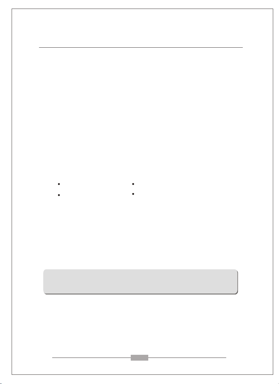
1.2 Checking List
Please make sure the following items are included with your LCD monitor:
Your monitor
User manual
If any of these items are missing, please contact with your dealer for
Technical support and customer service.
(DDC)1/2B compatible.
AC power cord
Signal cable
Introduction
Note:
Be sure to save original box and all packing material for transport in future if the
Monitor need .
1
Page 6
Chapter 2
Installation
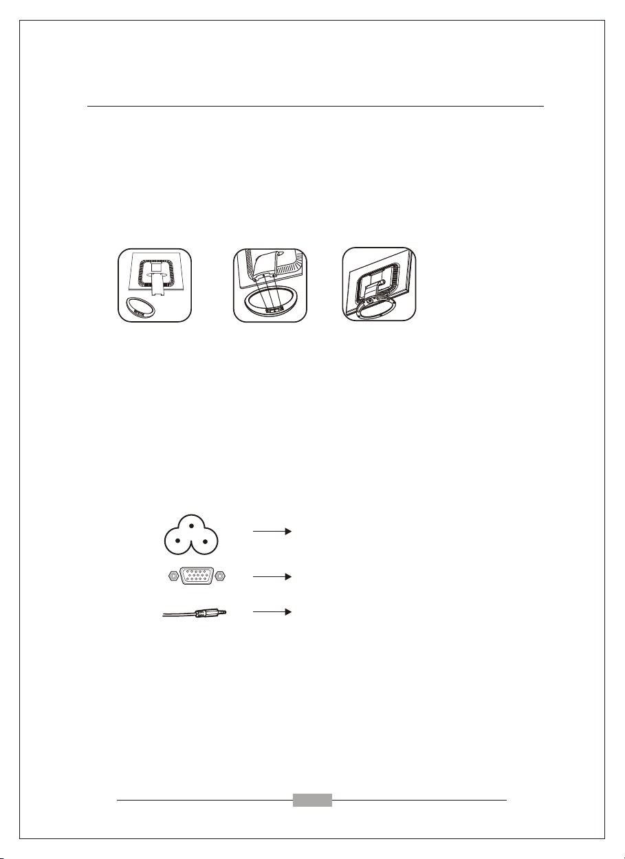
2.1 Install the pedestal
To attach the base to your monitor, please following the steps for
installation of the pedestal as below:
step 1 step 2 step 3
2.2 Connect your monitor to computer
2.2.1 Turn off your computer and unplug its power cable.
2.2.2 C power jack on the back of your monitoronnect the power cord to the .
Plug the computer and monitor power cables into a nearby outlet.
2.2.3
2.2.4
Turn your computer and monitor on, if your monitor display an image, you
have successfully installed the monitor. If the monitor does not display an
Image, check all the connections.
1. Power Jack
2. VGA Signal Cable
3. Audio Cable
Connecting the monitor to the computer and the power supply
2
Page 7

Chapter 3
3.1 Front Panel overview
Overview of your monitor
1 2 2 3 4
MENU DOWN UP AUTO
1.Menu Button
To push menu button turns on the menu, and it activates the items you highlight .
2.Select Button
To choose which function you need .you may choose DOWN counterclockwise or
UP clockwise.
3.Auto Button
Auto adjust the display mode to its utmost performance according to VGA setting.
5
4.Power Button( )
Use this button to turn the monitor on and off.
5.Power indicator
This light glows green or blue during normal operation and glows black during power off.
Glows orange during power saving mode.
3
Page 8

Chapter 4
OPERATION Direct - Access Features
4.1 SWITCHING THE MONITOR ON/OFF
This ON/OFF button is used for switching the monitor on and off.
Note: The ON/OFF switch does not disconnect the device from the
mains voltage. To completely disconnect the mains voltage.
Please remove the power plug from the socket.
4.2 POWER INDICATOR
This indicator lights up green or blue when the monitor operates normally.
If the monitor is in power saving mode, this indicator change to orange.
When monitor is turn off, this indicator change the color to dark.
4.3 VOLUME
This feature adjust the DOWN button to decrease the volume and UP button
to increase the volume.
Important information on audio playback
To achieve optimum sound quality from the monitor speakers, the audio
cable should be connected to the Line-Out socket (headphone socket) of the
computer. If you connect the audio cable to the Speaker-Out socket
(soundcard) of the computer, Please set the volume under Windows to range
between 20% - 40% of the maximum value to achieve optimum sound
quality.
4.4 MENU FEATURES
The following features can all be accessed by using your monitor's on
screen menu system. Once are finished. Making adjustments to a feature,
selecting the exit icon to turn off the menu.
Please follow the procedure of selection and adjust an item using the OSD
system as below steps for main functions adjustment.
Step 1: Press the MENU button to activate the OSD menu.
Step 2: If necessary, use the DOWN or UP button to mark an
Step 3: Press the MENU button to activate the highlighted icon.
Step 4: Use the DOWN or UP button to make the desired setting.
Step 5: Select the EXIT symbol to exit the OSD menu.
Step 6: Repeat step 2 through 5 to make further adjustments.
All changes are stored immediately.
The main menu appears on the screen with icons for the
setting functions.
other icon.
4
Page 9

Chapter 4
OPERATION Direct - Access Features
4.5 OSD MENU
1. Main menu
OSD main menu of controls gives you an overview of the selection of controls
available. When you want to make adjustment of the screen image, press and
release button Menu.
2. OSD Adjustment
You can choose where you would like OSD image to appear on your screen.
H-Position :
To move the OSD image horizontally left or right.
V-Position :
To move the OSD image vertically up or down.
Exit :
To exit the sub menu.
3. Language
You can choose one of the presetted languages you need.
4. Reset
Reset the currently highlighted control to the factory setting. User must be using
factory preset video mode to use this function.
5. Auto
Auto adjust display mode to its utmost performance according to VGA setting.
In the event of the display image needs further adjustment.
5
Page 10

Chapter 4
OPERATION Direct - Access Features
6. Color Select
Color Select Menu
COOL WARM
Select user mode
User color you can adjust to individual color gum intensity by yourself. Increase or
decrease red. green or blue depending upon which color is selected .
Cool
This control adjusts the color temperature of the screen image. This item are preset
by factory , you can not adjust these setting. The performance is bluer and brighter.
Warm
The performance is redder and closer to paper white.
7. Phase
To improve focus clarity an image stability.
8. H. Size
To increase or decrease the horizontal size of image.
9. V. Position
To move the picture image vertically up or down.
10. H. Position
To move the picture image horizontally left or right.
11. Contrast
Adjust the image brightness in relation to the background.
12. Brightness
Adjust the overall image and background screen brightness.
6
Page 11

Chapter 4
4.6 Preset Modes Timing Chart
OPERATION Direct - Access Features
Item
1
2
3
4
5
6
7
8
9
10
11
12
14",15": 1-10
17" : 1-12,19"
4.7 Plug and Play
Resolution
(dots x lines)
x
720
640
640
640
800
800
800
1024
1024
1024
1280
1280
x
x
x
x
x
x
x
x
x
x
x
400
480
480
480
600
600
600
768
768
768
1024
1024
Horizontal
Freq. (kHz)
31.47
31.47
37.86
37.50
37.88
48.08
46.87
48.36
56.48
60.02
63.98
80
Vertical
Freq. (Hz)
70
60
72.8
75
60.3
72.2
75
60
70.1
75
60
75
This monitor features the VESA DDC (Display Data Channel) standard, which when used
with a DDC compatible video card, will simplify the monitor's set up. With VESA DDC
1/2B, when the monitor is powered up, it will automatically notify a windows
9X/2000/XP host computer of its scanning frequencies, capabilities and characteristics.
windows 9X/2000/XP will automatically recognize the connection of the monitor and
select the appropriate display resolution.
7
Page 12
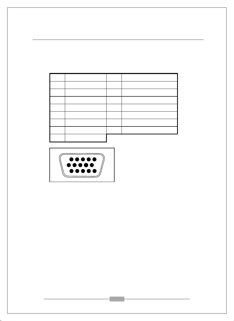
PIN Signal (D-sub) PIN Signal (D-sub)
1 Red 9 No connection
2 Green 10 Ground
3 Blue 11 Ground
4 Ground 12 SDA (FOR DDC)
5 Self Test 13 H. Sync
6 Red Ground 14 V. Sync
7 Green Ground 15 SCL (FOR DDC)
8 Blue Ground
Chapter 5
5.1 Signal connector pin assignment
Technical Information
+5V Input
1
6 10
11
15-Pin mini D-Type male connector
5.2 Visual Inspection
Permanently unlit or lit pixels
The standard of production techniques today cannot guarantee an absolutely faultfree screen display. A few isolated constant lit or unlit pixels may be present. The
maximum permitted number of pixels faults is stipulated in the stringent
international standard ISO 13406-2 (Class II).
Example: a 17" flat-screen monitor with a resolution of 1280 x 1024 has 1280 x
1024 = 1310720 pixels. Each pixel consists of three subpixels (red, green and blue),
so there are about 4 million dots in total.
According to ISO 13406-2 (Class II), a maximum of 6 pixels and 7 subpixels may
be defective, i. e. a total of 25 faulted dots. This corresponds to approx. 0.002 % of
the entire screen surface.
5
15
8
Page 13
Chapter 5
Technical Information
5.3 Trouble shooting
Before calling for service, check the information in this section to see if you
can remedy any problems by yourself. If you need assistance, please call the
dealer where you purchased the LCD monitor.
There is no SCREEN image
Please check these items:
The power cord is securely connected the monitor, the adaptor, and
the wall outlet.
Check the signal cable connection between the monitor and the
computer.
Adjust the brightness and contrast controls.
Monitor in power saving mode.
Display image is too large or small
Use the OSD controls to adjust Auto Setup.
The colors are discord
Signal cable properly connected?
Use OSD controls to adjust the color control setting.
The image is too light or too dark
Use OSD controls to adjust the brightness and contrast.
There is no sound or sound is low
Check the sound cable connection.
Make sure the computer sound program is working.
Adjust the volume on sound setting. Adjust your sound card or
computer volume setting.
Adjust the volume control keys on the monitor.
9
Page 14

Service
In case of technical problems with your Yakumo product,
contact our Hotline on +49-18 05/ 92 58 66 (12 cent/minute)
when calling from the Deutsche Telekom fixed network.
Warranty
If you think that you need to make a claim on your Yakumo
product under the warranty, call the Hotline on +49-18 05/
92 58 66 (12 cent/minute) when calling from the Deutsche
Telekom fixed network. Experienced staff will advise you
and arrange how you should proceed. Please do not send
any goods to the Yakumo Service Centre without obtaining
an RMA number from the hotline first, as otherwise the
goods will be returned unrepaired or refused.
Yakumo grants you a 2-year warranty from the invoice date.
In case of defects, the buyer only has a right to subsequent
performance. This subsequent performance will include
either repair or the delivery of a replacement product.
Exchanged units or parts will be the property of Yakumo.
Evidence of the warranty must be provided in the form of
proper proof of purchase (sales receipt or invoice).
Damage caused by improper handling, operation storage
or by force majeure or other external influences is not
covered by the warranty. The same applies to wearing
parts, e.g. rechargeable batteries (6 months).
In case of technical queries, go to the
Yakumo homepage at
www.yakumo.com or
send an e-mail to: info@yakumo.com.
Page 15
www.yakumo.com
Y_MAN_TFT_17SLi+NLPL.indd 1Y_MAN_TFT_17SLi+NLPL.indd 1 13.01.2005 18:01:01 Uhr13.01.2005 18:01:01 Uhr
 Loading...