

Page 1
Handbuch
Manual
Manuel
Yakumo TFT 19 AL
Flachbildschirm
Page 2

CONTENT
F.C.C Statement
Important safeguards
Chapter 1 Introduction
1.1 Features........................................................................................1
1.2 Checking List................................................................................1
Chapter 2 Installation
2.1 Connect your monitor to the computer ......................................2
Chapter 3 Over view of your monitor
3.1 Front Panel overview ..................................................................3
3.2 Rear Panel overview....................................................................3
Chapter 4 Operation
4.1 Power (ON/OFF) switch..............................................................4
4.2 Power indicator............................................................................4
4.3 AUTO ..........................................................................................4
4.4 Volume.........................................................................................4
4.5 Menu features ..............................................................................4
4.6 OSD menu ................................................................................. 5
4.7 Self test pattern ............................................................................ 8
4.8 Safety protection..........................................................................8
4.9 Preset modes timing chart ...........................................................9
Chapter 5 Technical information
5.1 Products Specifications...............................................................10
5.2 Signal Connector PIN Assignment..............................................11
5.3 Troubleshooting..........................................................................12
Visual Inspection............................................................................ 13
TCO99 Environmental Labelling (TCO99 only) ............................. 14
Assembly instruction for LCD monitor............................................16
Warning card ................................................................................. 17
Page 3

FEDERAL COMMUNICATIONS
COMMISSION(F.C.C) STATEMENT
his equipment has been tested and found to comply with the limits for a
T
Class B digital device. Pursuant to Part 15 of the FCC Rules. These limits are
designed to provide reasonable protection against harmful interference in
a residential installation. This equipment generates, uses and can radiate
radio frequency energy and, if not installed and used in accordance with
the instructions, may cause harmful interference to radio communications.
However, there is no guarantee that interference will not occur in a
particular installation. If this equipment does cause harmful interference to
radio or television reception, which can be determined by turning the
equipment off and on, the user is encouraged to try to correct the
interference by one or more of the following measures :
1. Reorient/Relocate the receiving antenna.
2. Increase the separation between the equipment and receiver.
3. Connect the equipment into an outlet on a circuit different from that to
which the receiver is connected.
4. Consult the dealer or an experienced radio/TV technician for help.
CAUTION:
Changes or modifications not expressly approved by the manufacturer
responsible for compliance could void the user’s authority to operate the
equipment.
Page 4

IMPORTANT SAFEGUARDS
Warnings
1. Read all of these instructions.
2. Unplug this monitor from the wall outlet before cleaning. Do not use liquid cleaners or aerosol
cleaners. Use a damp cloth for cleaning.
3. Do not use this monitor near water. For example near a bathtub, washbowl , kitchen sink, or
laundry tub, in a wet basement , or near a swimming pool, etc…
4. Do not place this monitor on an unstable cart, stand, or table. The monitor may fall, causing serious
injury to a child or, audit and serious damage to the appliance. Use only with a cart or stand
recommended by the manufacturer or sold with monitor. Wall or shelf mounting should follow the
manufacturer’s instructions, and should use a mounting kit approved by the manufacturer.
5. Slots and openings in the cabinet and the back or bottom are provided for ventilation, and to insure
reliable operation of the monitor and to protect it from overheating, these openings must not be
blocked or covered. The openings should never be blocked by placing the monitor on a bed, sofa,
rug, or other similar surface. This monitor should not be placed in built-in installation such as a
bookcase unless proper ventilation is provided.
6. Do not allow anything to rest on the power cord. Do not locate this monitor where the cord will
be abused by persons working on it.
7. Never push objects of any kind into this monitor through cabinet slots as they may touch dangerous
voltage points or short out parts that could result in electric shock. Never spill liquid of any kind on
the monitor.
8. Do not attempt to service this monitor yourself since opening or removing covers may expose you
to dangerous voltage or other hazards. Refer all servicing to qualified service personnel.
9. Unplug this monitor from the wall outlet and refer servicing to qualified service personnel under
the following CCCCCCCCCCCconditions:
a. When the power cord or plug is damaged or frayed.
b. If liquid has been spilled into the monitor.
c. If the monitor has been exposed to rain or water.
d. If the monitor has been dropped or the cabinet has been damaged.
e. When the monitor exhibits a distinct change in performance.
Page 5

Page 6

Introduction Chapter 1
IInnttrroodduuccttiioonn
1.1 Features
Microprocessor based with OSD (On Screen Display) control.
Compatible with standard IBM VGA, extended VGA, super VGA, IBM XGA modes, as
well as VESA resolution standards.
Universal power supply.
TCO 99 compliant.
Microsoft Windows 9x/2000/XP compatible & VESA Display Data Channel (DDC) 1/2B
compatible.
1.2 Checking List
Please make sure the following items are included with your LCD monitor.
Your monitor
AC Adapter
AC power cord
D-Sub Signal cable
Audio cable
If any of these items are missing, please contact your dealer for technical
support and custom service.
Note:
Be sure to save original box and all packing material for future transport.
1
Page 7
Installation
Installation
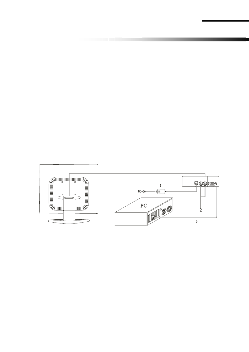
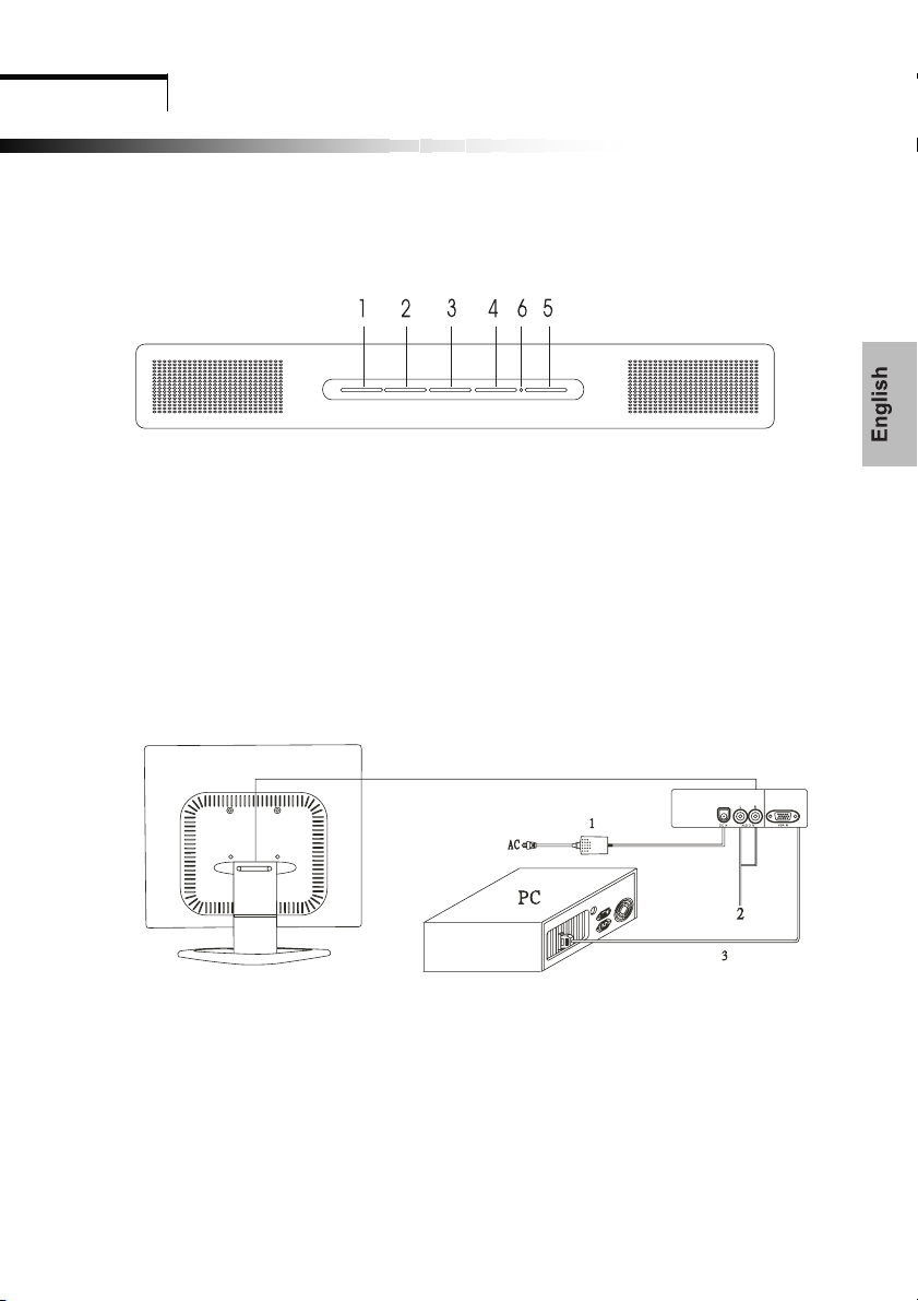
2.1 Connect your monitor to the computer
1 Turn off your computer and unplug its power cable.
2 Connect the power cable for your monitor to the DC adapter and connect the adapter to
the DC power jack on the back of your monitor.
NOTE : You must use the supplied power adapter.
3 Connect the AUDIO IN jack to RCA audio in for DVD or VTR.
4 Connect the D-Sub 15Pin signal cable to the video port on the back of your
computer.
5 Plug the computer and monitor power cables into a nearby outlet.
6 Turn your computer and monitor on, if your monitor display an image, you have
successfully installed the monitor. If the monitor does not display an image, check all the
connections and report steps 1-5 above.
Connecting the monitor to the computer and the power supply
2
Page 8
Over view of your monitor
Chapter 3
OOvveerr vviieeww ooff yyoouurr mmoonniittoorr
3.1 Front panel over view
1. Menu Button (MENU) 4. Auto Button (AUTO)
2. Select Button (DOWN)
3. Select Button (UP) 6. Power indicator
3.2 Rear panel over view
5. Power Button (POWE )
RR
R
1. DC IN
2. AUDIO IN
3. VGA IN
3
Page 9

Chapter 4
OPERATION Direct – Access Featur es
OOPPEERRAATTIIOON
N DDiirreecctt ––
AAcccceesss
s FFeeaattuurreess
4.1 Power ON/OFF Switch
This button is used to turn the monitor on and off.
NOTE : The ON/OFF switch does not disconnect the device from the main voltage. To
disconnect the mains voltage completely, please remove the power plug from the socket.
4.2 Power indicator
This indicator lights up green when the monitor operates normally.
If the monitor is in
When monitor is turn off
power saving mode, this indicator change to amber.
, this indicator
change to dark.
4.3 Auto
Press AUTO button and release the auto adjust display mode will tune to the utmost
performance according to VGA setting.
4.4 Volume
This feature adjust the DOWN button to decrease the volume and adjust UP button to
increase the volume.
4.5 Menu Features
The following features can all be accessed using your monitor on screen menu system.
When finished making adjustments to a feature, push the exit button to turn off the menu.
Please follow the procedure of selection and adjust an item using the OSD system as below
steps for main functions adjustment.
Step 1. Press Menu button to activate the OSD menu.
Step 2. Press Select Button DOWN or Select Button UP to scroll through and highlight the
main function list.
Step 3. When the desired function is highlight, press Menu Button a second time, the
highlight will change to a sub-menu near main menu.
Step 4. Press Menu Button and release again. The highlight of adjusted items and scroll bar
will change color from gray to blue.
Step 5. To make your adjustment, press DOWN counterclockwise to decrease or press UP
clockwise to increase the setting.
Step 6. Press and release Menu Button again to store the change. The scroll bar will
change color from blue to gray. You can select other functions to adjust by pressing
DOWN or UP. You can also select the exit icon and press Menu Button to go
back to the main menu.
Step 7. Report step 2 through 6 to make further adjustments.
4
Page 10

OPERATION Direct – Access Features
4.6 OSD menu
Main menu
OSD main menu of controls gives you an overview of the selection of controls available.
When you want to make adjustment of the screen image, press and release button Menu
Picture
1. Auto adjust
Press UP button, auto adjust the display mode to its optional VGA performance setting.
2. Brightness
Adjust the overall image and background screen brightness.
3. Contrast
Adjust the image brightness in relation to the background.
4. H Position
To move the picture image horizontally left or right.
5. V Position
To move the picture image vertically up or down.
6. Phase
To improve focus clarity and image stability.
7. Clock
To increase or decrease the horizontal size of image.
8. Exit
To exit the menu.
AAAAAAAAAAAAAAAAAA
5
Page 11

Advanced
A
1. Sharpness
Adjusts the picture sharpness.
2. Color
You have 4 color options.
Cool
This control adjusts the color temperature of the screen image. This item is preset by
the factory and can not be adjusted by the user. The performance is bluer and brighter.
Natural
This performance is reddish and closer to paper white.
Warm
The performance is yellowish and closer to paper white
User
You can adjust the individual color intensity to meet your personal needs.
User red
Increase or decrease red.
User green
Increase or decrease green.
User blue
Increase or decrease blue.
xit
E
To exit the main menu.
AAAA
Audio
1. Volume
DOWN to decrease volume, and UP to increase volume.
2. Mute
Choose this feature to mute the sound ON or OFF.
3. Exit
To exit the main menu.
OPERATION Direct – Access Features
6
Page 12

OPERATION Direct – Access Featur es
Options
O
L
1. OSD
To move the OSD image.
2. OSD H Position
To move the OSD image horizontally left or right.
3. OSD V Position
To move the OSD image vertically up or down.
LL LL
4.
Language
You can choose one of the nine languages.
5. Exit
To exit the main menu.
AAAA
Utilities
1. OSD timeout
You can select how long the monitor waits after the last adjust of the key to shut
off the OSD menu. The time setting choices are from 5 to 60 seconds.
2. OSD background
You can select opaque or translucent to change OSD background.
3. Source icon
You can select on or off to display OSD icon.
4. Exit
To exit the main menu.
AAAA
Reset
1. Memory recall
Reset the currently highlight control to the factory setting. User must be using
factory preset video mode to use this function.
2. Exit
To exit the main menu.
Exit
To exit the OSD menu.
7
Page 13

OPERATION Direct – Access Features
4.7 Self test pattern
When the computer’s video signal is not reaching the monitor, the monitor will display a self
test pattern.
4.8 Safety protection
When the frequency of the video signal from your computer is out of range, the monitor will
protect by itself and a warning OSD message will appear on the screen.
8
Page 14

OPERATION Direct – Access Features
4.9 Preset Modes Timing Chart
Resolution Horizontal Vertical
720 × 400 31.47 KHz 70.0 Hz
640 × 480 31.47 KHz 60.0 Hz
640 × 480 37.86 KHz 72.8 Hz
640 × 480 37.50 KHz 75.0 Hz
800 × 600 37.88 KHz 60.3 Hz
800 × 600 48.08 KHz 72.2 Hz
800 × 600 46.87 KHz 75.0 Hz
1024 × 768 48.36 KHz 60.0 Hz
1024 × 768 56.48 KHz 70.1 Hz
1024 × 768 60.02 KHz 75.0 Hz
1280x1024 63.98 KHz 60.0 Hz
1280x1024 79.98 KHz 75.0 Hz
9
Page 15

Chapter 5 Technical Information
TTeecchhnniiccaall IInnffoorrmmaattiioon
n
5.1 Products Specifications
Inch Size
Max. Resolution
Recommend Resolution
Horizontal Freq.
Vertical Freq.
Active Display Area
Bandwidth
User Control
OSD Functions
Adapter power input
Power Consumption
(under)
Connector Signal
Brightness, Contrast, H-Position, V-Position, H-Size,
Phase, Color, Auto, Reset, Language, OSD, Exit
19”
1280*1024@75Hz
1280*1024@60Hz
31-80KHz
60-75Hz
376*301mm
135MHz
4 key Switch
AC 100 - 240V / DC12V
60W
D-sub 15Pin
Safety & EMI
Dimension (Packing)
Weight Gross/Net
Multimedia Feature
(Optional)
UL/CUL, TUV/GS, CE, FCC/DOC, CB, VCCI,
TCO99, BSMI, C-Tick, CCC, 13406-2
484(W)x500(H)x150(D) mm
7.3KG / 6.1KG
2.5W +2.5W (8O)
10
Page 16
Technical Information
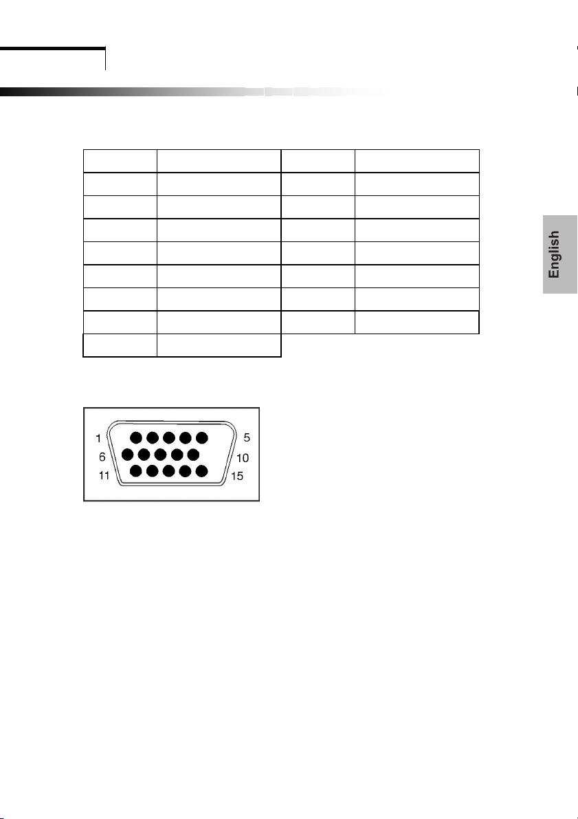
5.2 Signal connector PIN assignment
D-Sub 15 Pin Signal connector PIN assignment
PIN Signal (D-sub) PIN Signal (D-sub)
1 Red 9 VDD from PC For DDC
2 Green 10 Ground
3 Blue 11 Ground
4 Ground 12 SDA (For DDC)
5 Self Test 13 H. Sync.
6 Red Ground 14 V. Sync.
7 Green Ground 15 SCL (For DDC)
8 Blue Ground
Signal connector
11
Page 17

Technical Information
5.3 Troubleshooting
Before calling for service, check the information in this section to see if you can remedy any
problems by yourself. If you need assistance, please call the dealer where you purchased the
LCD monitor.
There is no SCREEN image
The power cord is securely connected the monitor, the adapter, and the wall outlet.
Check the signal cable connection between the monitor and the computer.
Adjust the brightness and contrast controls.
Monitor is in power saving mode.
Display image is too large or small
Use the OSD controls to adjust Auto setup.
The color are distorted
Signal cable properly connected.
Use OSD controls to adjust the color control setting.
The image is too light or too dark
Use OSD controls to adjust the brightness and contrast.
There is no sound or sound is low
Check the sound cable connection.
Make sure the computers sound program is working.
Adjust the volume on sound setting.
Adjust the volume control keys on the monitor.
12
Page 18

]
R,G,B, Black and White.
Inspection pattern for electrical defect should be pure
L: length, N:count ]
Light leakage not allowed.
Image sticking Image sticking pattern shall not be to persist longer than 10
seconds in the next pattern.
Glue/stain/dirt Glue, non-removable stain and dirt which are visible in the
inspection area are not acceptable.
13
Page 19

TCO99 Environmental Labelling (TCO99 only)
Congratulations!
You have just purchased a TCO’99 approved and labelled product! Your choice has provided you with a product
developed for professional use. Your purchase has also contributed to reducing the burden on the environment
and also to the further development of environmentally adapted electronics products.
This product meets the requirements for the TCO’99 scheme which provides for an international environmental
and quality labelling of personal computers. The labelling scheme was developed as a joint effort by the TCO
(The Swedish Confederation of Professional Employees), Svenska Naturskyddsforeningen (The Swedish Society
for Nature Conservation), Statens Energimyndighet (The Swedish National Energy Administration) and SEMKO
AB.
The requirements cover a wide range of issues: environment, ergonomics, usability, reduction of electric and
magnetic fields, energy consumption and clectrical safety.
Why do we have environmentally labelled computers?
In many countries, environmental labelling has become an established method for encouraging the adaptation of
good and services to the environment. The main problem, as far as computers and other electronics equipment
are concerned, is that environmentally harmful substances are used both in the products and during their
manufacture. Since it is not so far possible to satisfactorily recycle the majority of electronics equipment, most
of these potentially damaging substances sooner or later enter nature.
There are also other characteristics of a computer, such as energy consumption levels, that are important from the
viewpoints of both the work (internal) and natural (external) environments. Since all methods of electricity
generation have a negative effect on the environment (e.g. acidic and climate-influencing emissions, radioactive
waste), it is vital to save energy. Electronics equipment in offices is often left running continuously and thereby
consumes a lot of energy.
What does the environmental labelling involve?
The environmental demands has been developed by Svenska Naturskyddsforeningen (The Swedish Society for
Nature Conservation). These demands impose restrictions on the presence and use of heavy metals, brominated
and chlorinated flame retardants, CFCs (freons) and chlorinated solvents, among other things. The product must
be prepared for recycling and the manufacturer is obliged to have an environmental policy which must be adhered
to in each country where the company implements its operational policy.
The energy requirements include a demand that the computer and/or display, after a certain period of inactivity,
shall reduce its power consumption to a lower level in one or more stages. The length of time to reactivate the
computer shall be reasonable for the user.
14
Page 20

TCO99 Environmental Labelling ( TCO99 only)
Below you will find a brief summary of the environmental requirements met by this product. The complete
environmental criteria document may be ordered form:
TCO Development
SE-114 94 Stockholm, Sweden
Fax: +46 8 782 92 07
Email (Internet): development@tco.se
Current information regarding TCO’99 approved and labelled products may also be obtained via the Internet, using the
address: http://www.tco-info.com/
Environmental requirements
Flame retardants
Flame retardants are present in printed circuit boards, cables, wires, casings and housings. Their purpose is to prevent,
or at least to delay the spread of fire. Up to 30% of the plastic in a computer casting can consist of flame retardant
substances. Most flame retardants contain bromine or chloride, and those flame retardants are chemically related to
another group of environmental toxins, PCBs. Both the flame retardants containing bromine or chloride and the
PCBs are suspected of giving rise to severe health effects, including reproductive damage in fish-eating birds and
mammals, due to the bio-accumulative* processes. Flame retardants have been found in human blood and
researchers fear that disturbances in foetus development may occur..
The relevant TCO’99 demand requires that plastic components weighing more than 25 grams must not contain flame
retardants with organically bound bromine or chlorine. Flame retardants are allowed in the printed circuit boards
since no substitutes are available.
Cadmium**
Cadmium is present in rechargeable batteries and in the colour-generating layers of certain computer displays.
Cadmium damages the nervous system and is toxic in high doses. The relevant TCO’99 requirement states that
batteries, the colour-generating layers of display screens and the electrical or electronics components must not contain
any cadmium.
Mercury**
Mercury is sometimes found in batteries, relays and switches. It damages the nervous system and is toxic in high
doses. The relevant TCO’99 requirement states that batteries may not contain any mercury. It also demands that
mercury is not present in any of the electrical or electronics components associated with the labelled unit. There is
however one exception. Mercury is, for the time being, permitted in the back light system of flat panel monitors as
there today is no commercially available alternative. TCO aims on removing this exception when a mercury free
alternative is available.
CFCs (freons)
The relevant TCO’99 requirement states that neither CFCs nor HCFCs may be used during the manufacture and
assembly of the product. CFCs (freons) are sometimes used for washing printed circuit boards. CFCs break down
ozone and thereby damage the ozone layer in the stratosphere, causing increased reception on earth of ultraviolet light
with e.g. increased risks of skin cancer (malignant melanoma) as a consequence.
Lead**
Lead can be found in picture tubes, display screens, solders and capacitors. Lead damages the nervous system and in
higher doses, causes lead poisoning. The relevant TCO’99 requirement permits the inclusion of lead since no
replacement has yet been developed.
_____________________
* Bio-accumulative is defined as substances which accumulate within living organisms
** Lead, Cadmium and Mercury are heavy metals which are Bio-accumulative.
29 January, 1999
15
Page 21

Assembly instruction for LCD monitor
16
Page 22

Warning Card
17
 Loading...