

Page 1

TM
®
LOCKN’LOAD TRACK MOUNTING KIT
TOYOTA FORTUNER GX 2015+
2 BAR TRACK HEAVY DUTY ROOF RACK SYSTEM
MAX VEHICLE ROOF LOAD RATING: 100KG
TOTAL LOAD EQUALS WEIGHT OF ROOF RACKS + ACCESSORIES + CARGO
FIRST TIME INSTALLATION
• Please read instructions carefully before installation.
• Check the contents of kit. Contact your YAKIMA dealer if any parts appear missing or damaged.
• Clean your roof thoroughly prior to fitting the LOCKN’LOAD Track Heavy Duty Roof Rack System.
• Place these instructions in the vehicle’s glove box after installation is complete.
TOOLS REQUIRED:
• Marking Pen
• Tape Measure
• Masking Tape
• Power or Cordless Drill
• Drill Bit Stop
• Vacuum Cleaner
• Mastic Silicone Sealant
• Fine Tooth Hacksaw
• Hammer
• Rubber Mallet (Optional)
• #2 Phillips Head Screwdriver
• Zinc Rich Cold Galvanising Coating
• Flat Blade Screwdriver
• 10mm Open Ended Spanner
• 13mm Socket or Spanner
• Rivet Gun
• Scissors
• Centre Punch
• Automotive Degreaser
• Automotive Adhesive
• Thread Locking Compound
KIT CONTENTS
ITEM COMPONENT
QTY ITEM
COMPONENT
1. Track Toyota Fortuner Right Hand Side x1 6. Rivet x18
2. Track Toyota Fortuner Left Hand Side x1 7. Drill Bit x1
3. Track Nut Plate x4 8. M6 Hex Screw x8
4. M6 Washer x8 9. End Cap Front Left & Rear Right x2
5. M6 Spring Washer x8
LEG AND BAR COMPONENTS SOLD SEPARATELY
3
7
10. End Cap Front Right & Rear Left x2
1
6
QTY
2
5
9
10
28-13-331-Rev1 1/11
8
4
Page 2

1
2
TRACK INSTALLATION
BEFORE BEGINNING INSTALLATION
Clean roof thoroughly and allow to dry before beginning
installation.
REMOVE ROOF CHANNEL TRIM
Gently lever the rubber roof channel trim with a Flat Blade
Screwdriver (wrap tape around end of Screwdriver to prevent
paint scratching). Then using fingertips pull carefully upwards
and unhook plastic clips that are attached to the roof underneath
each end of the trim.
Store channel trim in a safe location for use in Step 14.
TRACK ORIENTATION
The extrusion on side of Tracks faces inside of vehicle as
shown, with rounded rectangular cut outs at rear of vehicle.
The help of an assistant is recommended to install Tracks.
Extrusion
NOTE - image as viewed
from rear of vehicle
It is recommended to install one Track at a time.
Rounded rectangular cut
out at rear of vehicle
TRACK MEASUREMENTS
3
Apply Masking Tape along roof channel.
Using a Tape Measure, measure
350mm back from the edge of the
windscreen as shown and record.
LEFT Track
Vehicle Front
RIGHT Track
NOTE - image as viewed from rear of vehicle
APPLY MASKING TAPE
4
Apply lengths of Masking Tape
along window and door seals.
Vehicle Front
350mm
NOTE - This prevents drill swarf from getting caught.
28-13-331-Rev1 2/11
Page 3

5
6
ALIGN TRACK INTO ROOF CHANNEL
Place Track into roof channel, lining up the front of the track end with the tape line measured in
Step 3. Ensure Track orientation and spacing is correct as shown, with rounded rectangular cut
outs at rear of vehicle.
Extrusion
350mm
MARK TRACK HOLES
With the help of an assistant, hold Track down firmly in roof channel and mark all holes using a
Marking Pen. Ensure Track does not move during this process. Remove Track.
CENTRE PUNCH
7
28-13-331-Rev1 3/11
HOLES
Using a Centre
Punch and
Hammer,
accurately Centre
Punch the holes
marked in the
previous Step.
8
Vehicle
DRILL ROOF
Using the 4.9mm Drill Bit provided and
a Drill Stop which allows a drill depth
of 6-8mm, carefully drill through the
roof at each centre marked location.
Ensure a drilling angle perpendicular
to the roof surface is maintained
throughout.
Front
these holes. Always use a Drill Stop.
Drill Stop
! !
Pay extra attention when drilling
Warning!
6-8mm
Page 4

9
REMOVE SWARF
Avoid pushing swarf into
the newly drilled holes
by removing swarf from
roof channel with a
Vacuum Cleaner.
Vacuum swarf
10
APPLY PROTECTIVE SEALANTS
Stage 1
Liberally apply a Zinc Rich Cold Galvanising Solution to the
inside surface and surrounds of each drilled hole. Allow
solution to become touch dry before proceeding with
Stage 2 (approx. 10 min depending on product used).
Stage 2
Liberally apply a Mastic Silicone Sealant to the inside
surface and surrounds of each hole.
11
Stage 1
Apply liberally
in and around
holes.
Allow to dry.
PLACE TRACKS BACK INTO ROOF CHANNEL
Accurately place Tracks over drilled holes in roof channel, ensuring Track
orientation is correct as shown, with rounded rectangular cut outs at rear
of vehicle.
Extrusion
Stage 2
Apply liberally
in and around
holes.
END CAP FITMENT
12
28-13-331-Rev1 4/11
Assemble End Caps within Tracks as shown,
taking note of End Cap orientation.
This edge faces
towards middle
of vehicle
Align End Cap and
slide into position
Page 5
13
TRACK INSTALLATION
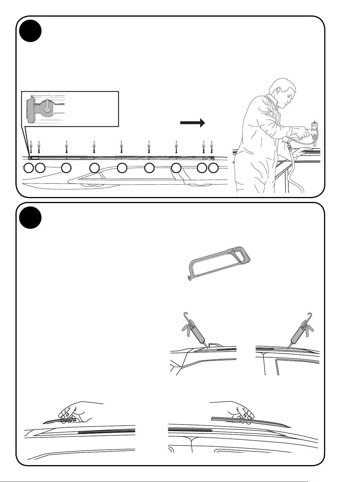
Align Track and secure End Caps by inserting all Rivets in their respective holes through Track into
roof channel.
Using a Rivet Gun, activate each Rivet starting from the centre Rivet, then working consecutively
outwards as shown.
To secure End Caps,
insert Rivet through
End Cap and Track
Vehicle Front
14
6 78 9
CUT ROOF CHANNEL TRIM TO SIZE AND REFIT
4
12 3
5
Thoroughly clean exposed roof channel at
front and rear of Tracks using an Automotive
Degreaser before refitting roof trim.
To conceal exposed roof channel at front
and rear of Tracks, cut to length the original
roof trim removed in Step 1.
Measure out the required length by
positioning the trim along roof channel.
The front needs to be measured so the end
of trim sits under windscreen rubber.
Use a pencil to mark reference line on trim.
Remove trim from vehicle and cut to
length using a Fine Tooth Hacksaw.
Liberally apply an Automotive Adhesive
to roof channel then refit trim pieces.
Wipe off any excess adhesive with
a damp cloth and allow to dry.
Use a fine tooth
Hacksaw due to metal
inside rubber roof
trim. Alternatively tin
snips can be used
Liberally apply an
Automotive Adhesive
such as Sikaflex
Rear Front
28-13-331-Rev1 5/11
Page 6
15
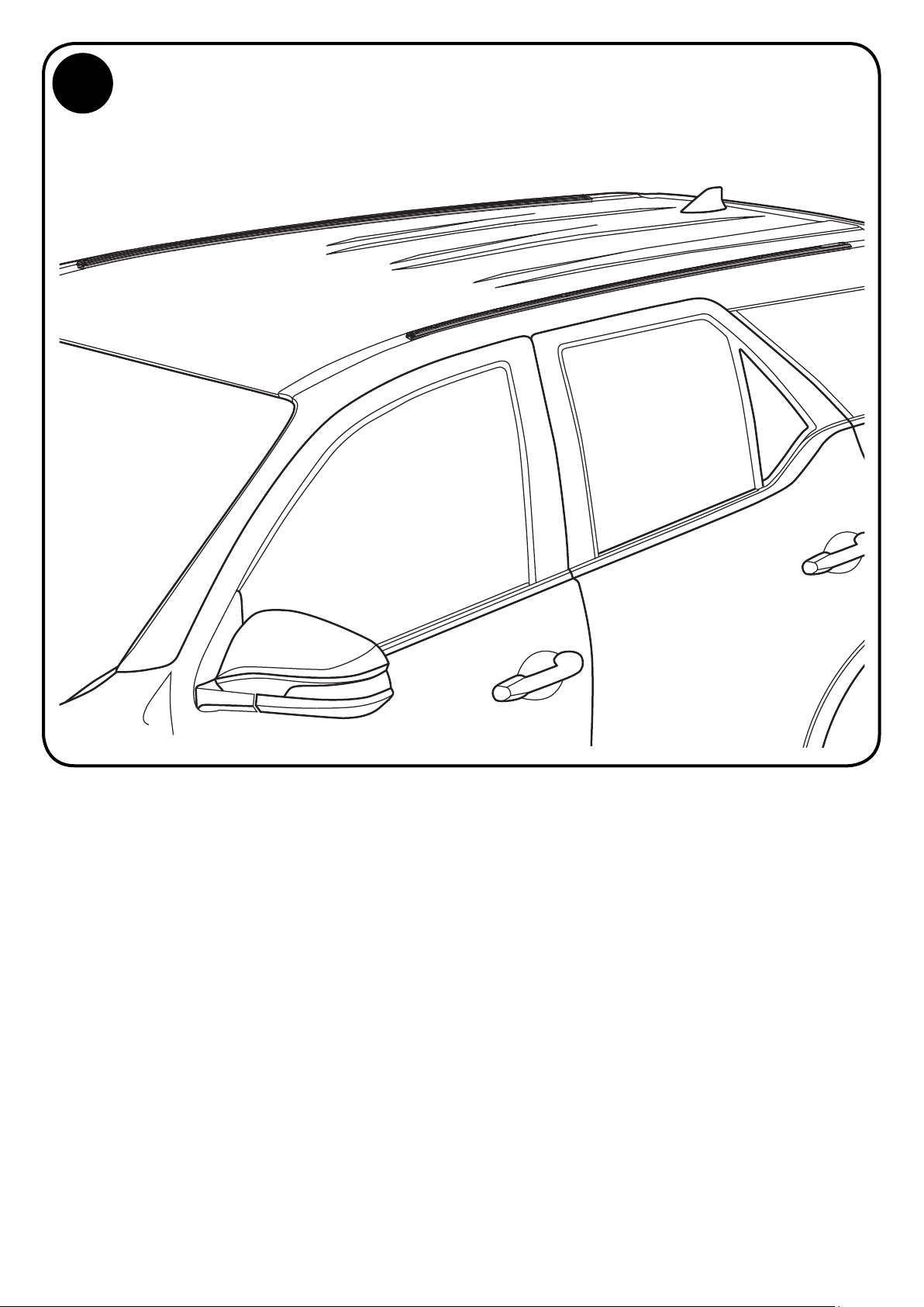
TRACK INSTALLATION COMPLETE
Check both Tracks are secured to the vehicle as per these installation instructions.
For assistance contact your local Yakima dealer.
PLEASE SEE NEXT PAGE FOR BAR INSTALLATION
28-13-331-Rev1 6/11
Page 7
BAR INSTALLATION
1
3
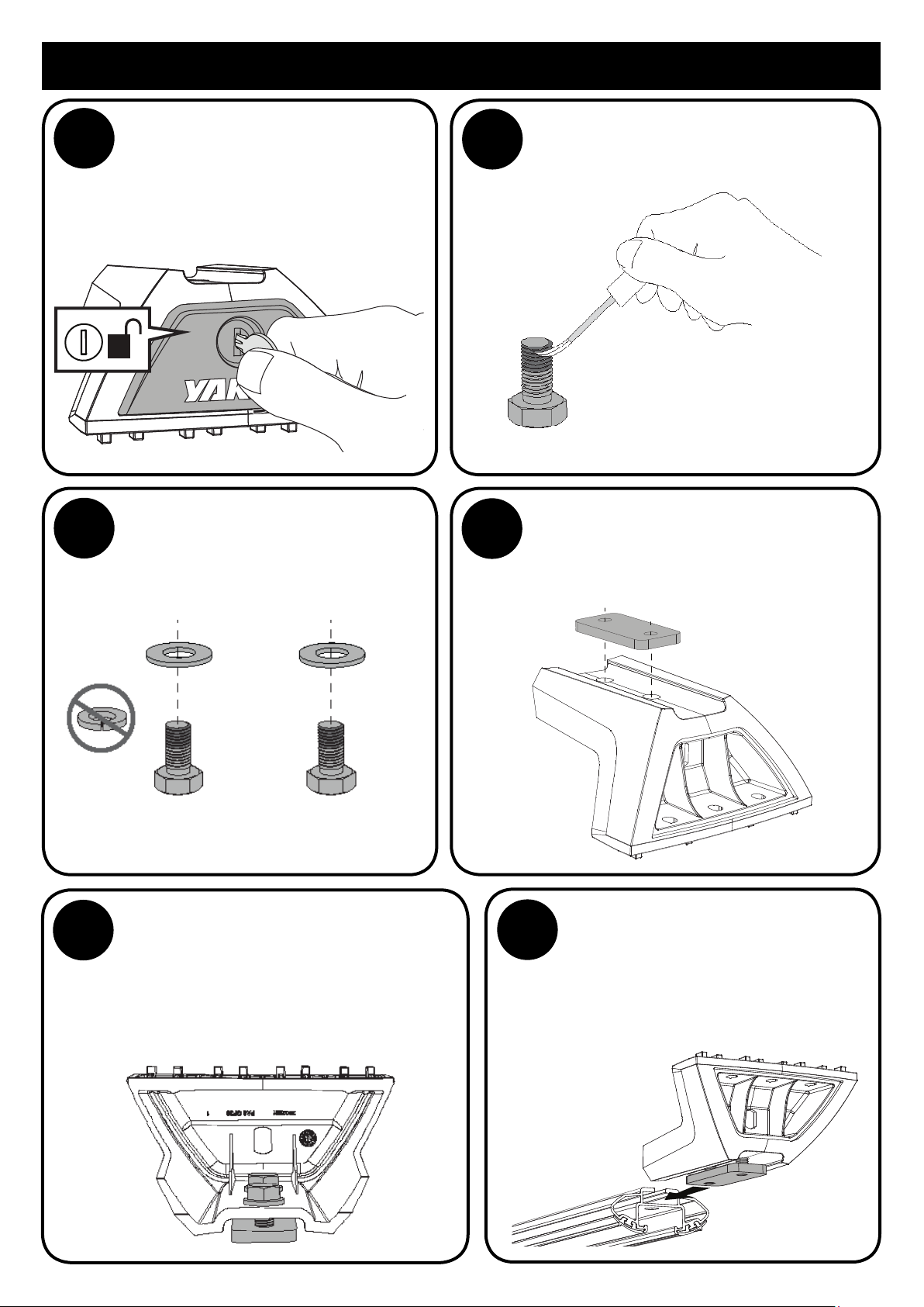
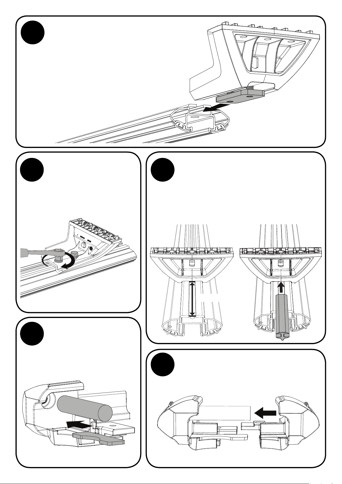
REMOVE LEG COVERS
Using the keys supplied in the
LOCKN’LOAD Leg Kit (sold separately),
remove all Leg Covers.
Assemble 1 x M8 Washer onto each M8
Set Screw 16mm (with thread locking
compound applied).
The spring washers supplied in
the kit do not need to be used.
2
4
Apply a high strength (red) thread
locking compound* to the first half of
thread on each M8 Set Screw 16mm.
If bars are removed in the
future and legs repositioned,
thread locking compound
should be reapplied.
*Thread locking compound not supplied.
LEG ASSEMBLY
From the LOCKN’LOAD Leg Kit, position
Nut Plates over holes on top of Legs.
Complete the next steps as soon as possible, before
thread locking compound cures. Refer to thread
locking compound’s specification for curing time.
Loosely finger tighten Nut Plates to
5
Legs as shown using the screw+washer
assemblies from the previous step.
For the next step, ensure there is a sufficient
gap between the Nut Plates and Legs.
6
INSERT LEGS
Slide Leg assemblies into the underside
channel of LOCKN’LOAD Bars (sold
separately). If Leg assemblies will not
slide in, loosen Screws to increase gap.
28-13-331-Rev1 7/11
Page 8
=
=
=
7
9
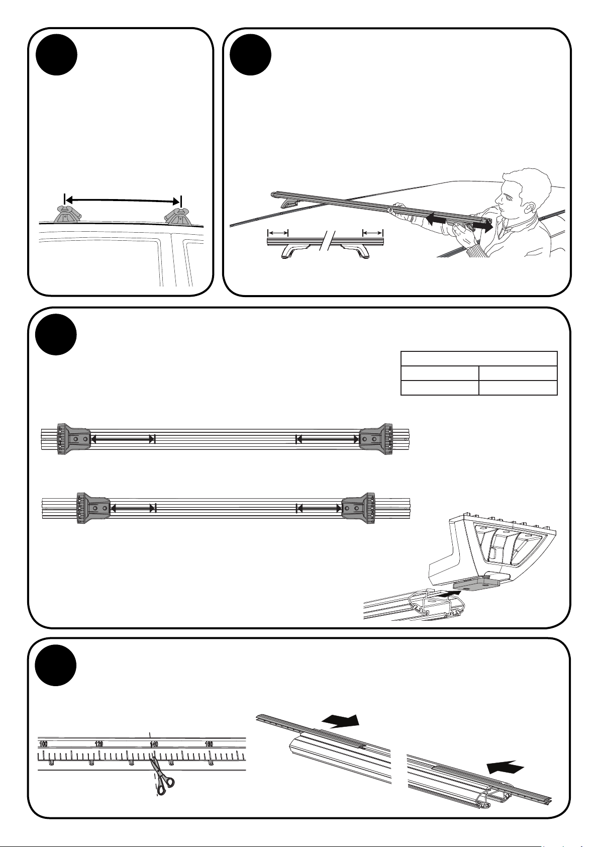
BAR LOCATION
IMPORTANT: Before
beginning Bar installation,
identify where along the
Track you want the Front
and Rear Bars fitted. We
recommend a minimum of
700mm between Bars.
≥
700mm
CHECK BAR SLOT MEASUREMENTS
Using a Tape Measure record Leg to underside slot distance of
each bar in the table (right). Ensure measurement is taken from
the centre of the Legs as shown. The ends of each bar should
be the same measurement respectively, if not, repeat Step 8.
8
BAR PLACEMENT
Carefully place a Bar assembly over Track. Take care
not to damage vehicle. Slide Legs along Bar until both
legs are securely positioned within Track. Use a Tape
Measure to ensure even Bar overhang on each side, readjust if required. Finger tighten one Screw on each Leg
to secure Leg position along Bar. Repeat for remaining
bar assembly then carefully remove Bars from vehicle.
NOTE - Front and Rear Bars require individual adjustment due to tapered
roof. Bars must be installed perpendicular to Tracks.
BAR SLOT MEASUREMENTS
Front Bar (X) Rear Bar (Y)
______mm x2 ______mm x2
Remove Legs from Bar once equal measurement is obtained
and recorded. Loosen the previously finger tightened screw
on each leg, keeping Nut Plate and Screw assemblies in
place as shown.
BAR SLOT COVERS
10
Cut Bar Slot Covers as per measurements recorded in the table above and insert into underside
channel of front and rear Bar ends as shown.
X
Y
X = X
Y = Y
X
Y
NOTE - Bar Slot Covers to be
inserted with flat side visible
28-13-331-Rev1 8/11
Page 9
11
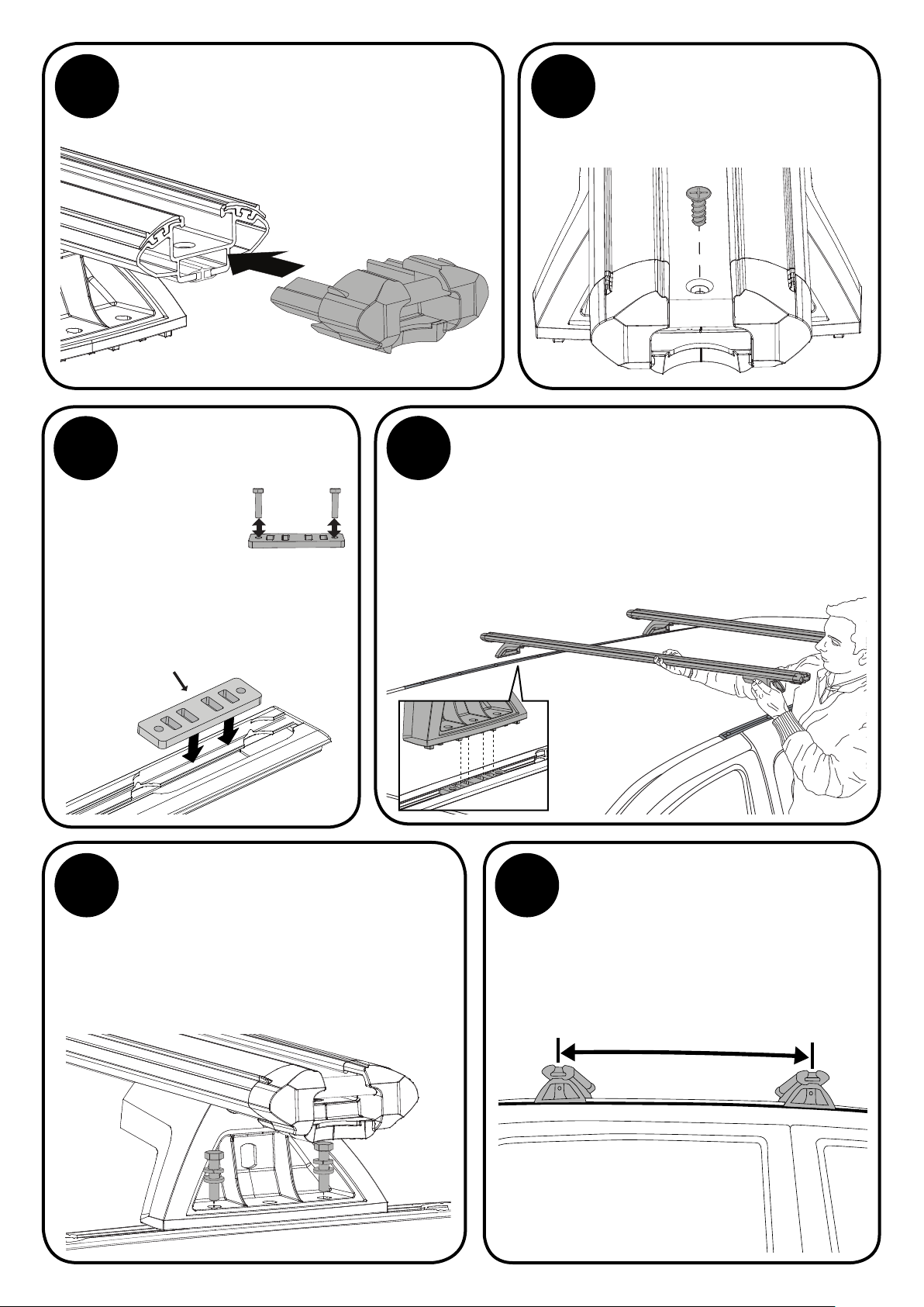
INSERT LEGS
Slide Leg assemblies into the underside channel of
LOCKN’LOAD Bars. Slide in until Leg reaches Slot Cover.
Do not compress slot cover.
12
14
SECURE LEGS TO BARS
Tighten all M8 Set Screws
to 7Nm using a 13mm
Socket Wrench.
END CAP ASSEMBLY
From the LOCKN’LOAD Leg
Kit, insert Bottle Openers and
Pins into the End Cap Halves.
13
15
BAR SLOT COVERS (OUTSIDE LEG)
Measure the Bar channel outside of the Legs and
subtract 20mm from this measurement. Using the
remaining pieces of Slot Cover from Step 10, cut to
this length and insert into the underside channel of
each Bar end as shown.
-20mm
Connect all End Cap Halves together.
28-13-331-Rev1 9/11
Page 10
SECURE END CAPS TO BARS
16 17
Insert the End Caps as shown. A Rubber Mallet
can be used to assist installation.
Secure using Plastite Screw
(from LOCKN’LOAD Leg Kit).
Tighten using a #2 Phillips Head
Screwdriver.
INSERT NUT PLATES
18
Run all M6 Hex
Screws through
Nut Plates to
remove burrs.
33
20 21
Insert two (2) Nut Plates into
each Track as shown.
Nut Plate
SECURE BARS TO TRACKS
From the LOCKN’LOAD Track Kit, assemble
1 x M6 Spring Washer and 1 x M6 Washer
onto each M6 Hex Screw as shown. Insert
through the outer holes on Legs into Nut
Plate as shown. Finger tighten Screws.
19
BAR FITMENT
Slide Nut Plates within Track into position for front and
rear Bar placement (it doesn’t have to be exact). Place
Bar assembly onto Tracks, carefully locating the four
central raised notches on base of Legs into the cut
outs on Nut Plates as shown. Take care not to damage
vehicle. Repeat for remaining Bar.
Position front and rear Bars along
Tracks as required, ensuring there
is a minimum distance of 700mm
between each Bar. Measure from
the centre of each Leg as shown.
≥
700mm
15
28-13-331-Rev1 10/11
Page 11
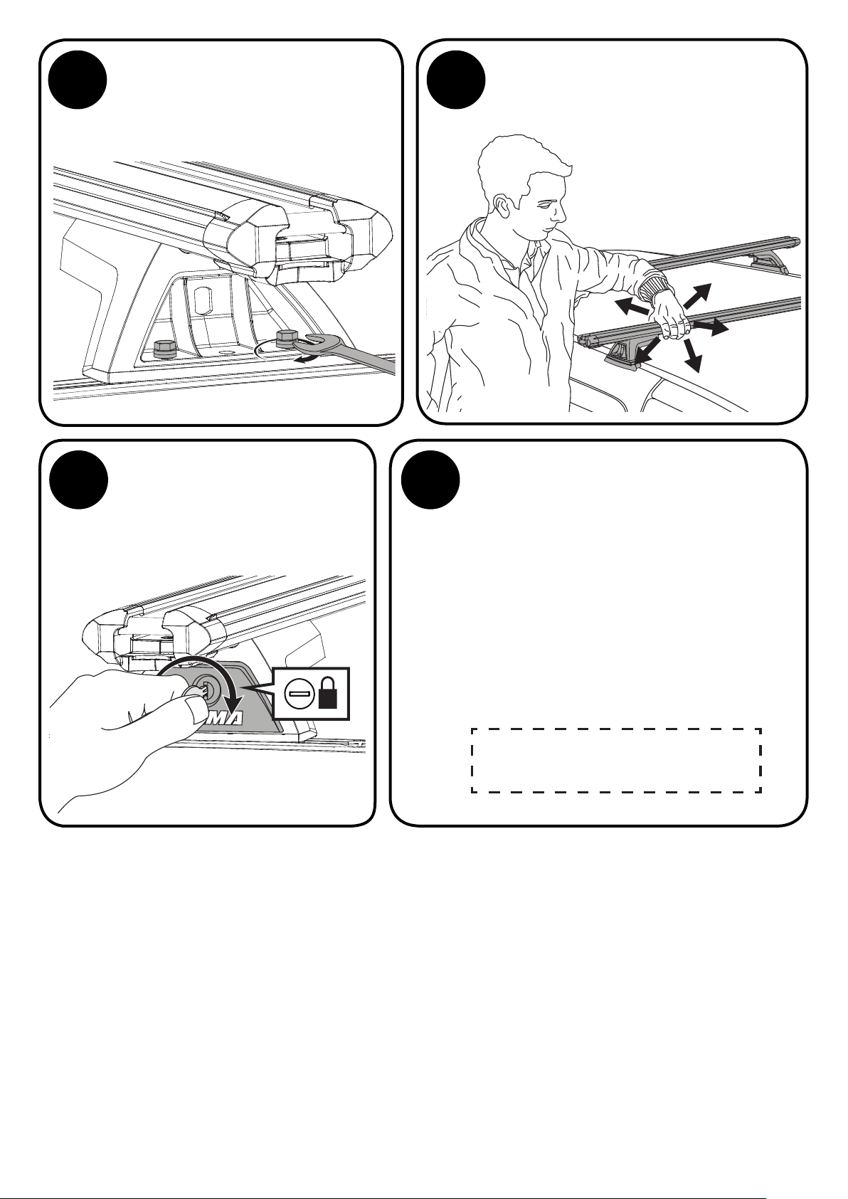
Tighten all M6 Hex Screws to 5Nm using
22 23
a 10mm Open Ended Spanner
Do not over tighten.
CHECK BAR LEGS ARE SECURE
Check all Bar Legs are secure.
FIT LEG COVERS
24 25
Using the keys and Covers
supplied in the LOCKN’LOAD Leg
Kit, fit and lock all Leg Covers.
BAR KEYS
Place one key on the vehicle key ring and put
the other away safely, or store with the spare
vehicle key.
Write the key number (which is stamped on the
key) in the box provided. Replacement keys
are available from Yakima stockists, visit
www.yakima.com.au or www.yakima.co.nz to
find your nearest store or contact us directly
on 1800 143 548 (AU) or 0800 4776 722 (NZ).
Key Number:
28-13-331-Rev1 11/11
 Loading...