

Front Panel
FCC ID: K66VXR-9000U
Operating Manual
(9)(7) (4)
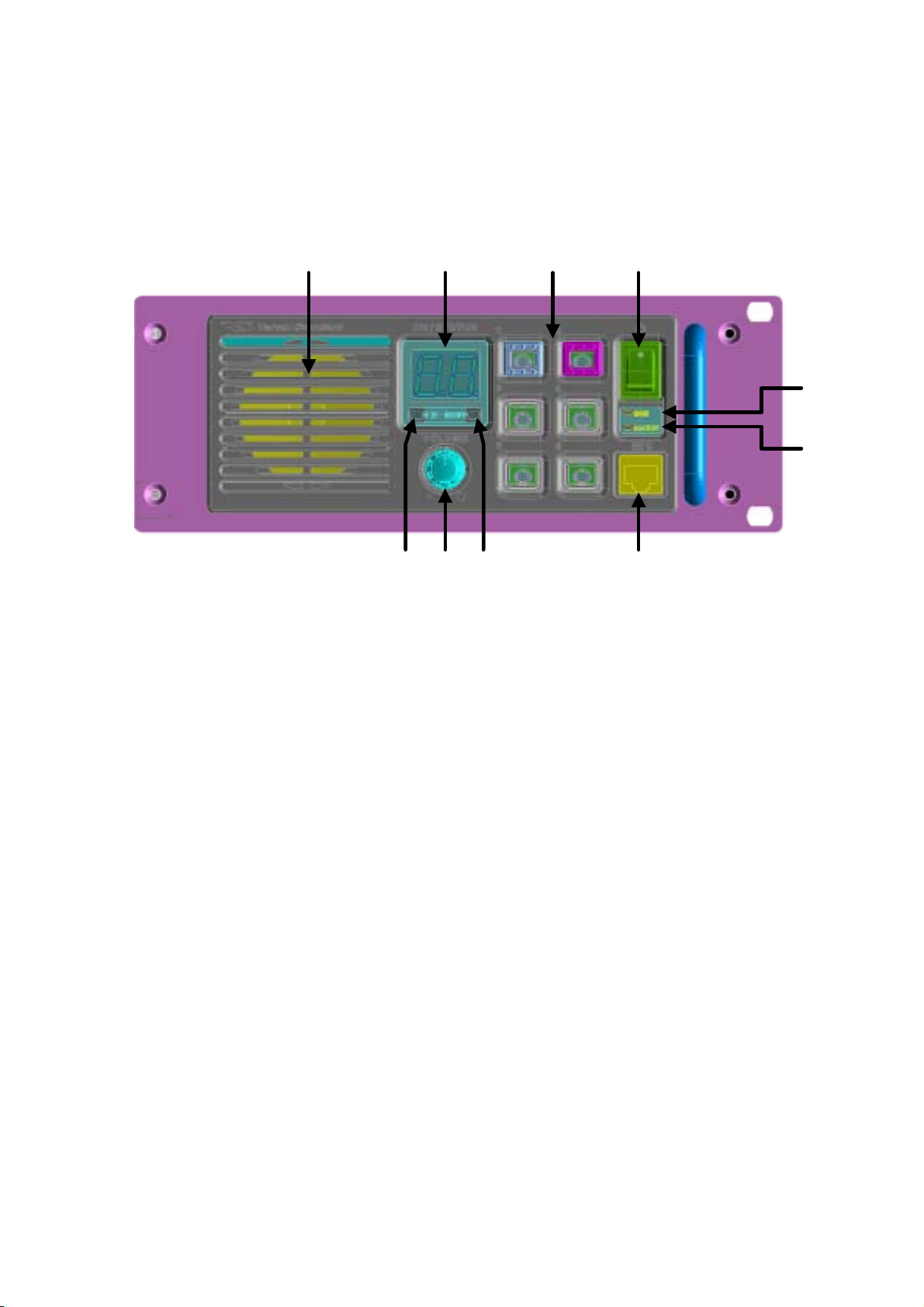
(1) Power Switch
Operate the switch to turn the repeater On and Off.
(8)
(5)(6)(10)
(1)
(2)
(3)
(2) Power Indicator (Main)
A green LED lights when the main power source is used.
(3) Power Indicator (Backup)
A red LED lights whrn the backup power source is used.
(4) Microphone Jack
Connect the microphone plug to this jack. This jack is also used for writing and reading
channel frequency or other configurations via COM Port of PC on which the clone editor
(CE60) is running.
(5) Programmable Function Key
Six push keys are programmable function key (PFK) which have orange indicator
inside each of them. Each key can be programmed two functions for long push and short
push.
1/13
Vertex Standard Co., Ltd.

FCC ID: K66VXR-9000U
Operating Manual
(6) Numeric Display
The display is consisted of two digits seven-segment LED, which shows channel number when the
repeater works normally. An error code is displlayed in case the repeater has a trouble with it.
(7) TX Indicator
A red LED lights when the repeater is transmitting.
(8) Busy Indicator
A green LED lights when the receiving channel is busy.
(9) Volume Knob
Volume knob to adjust the output level of front speaker and external speaker jack on the back panel.
(10) Speaker
Internal Speaker.
2/13
Vertex Standard Co., Ltd.
Rear Panel
FCC ID: K66VXR-9000U
Operating Manual
(1)
(2)
(3) (4)
(7)
(5)(6)
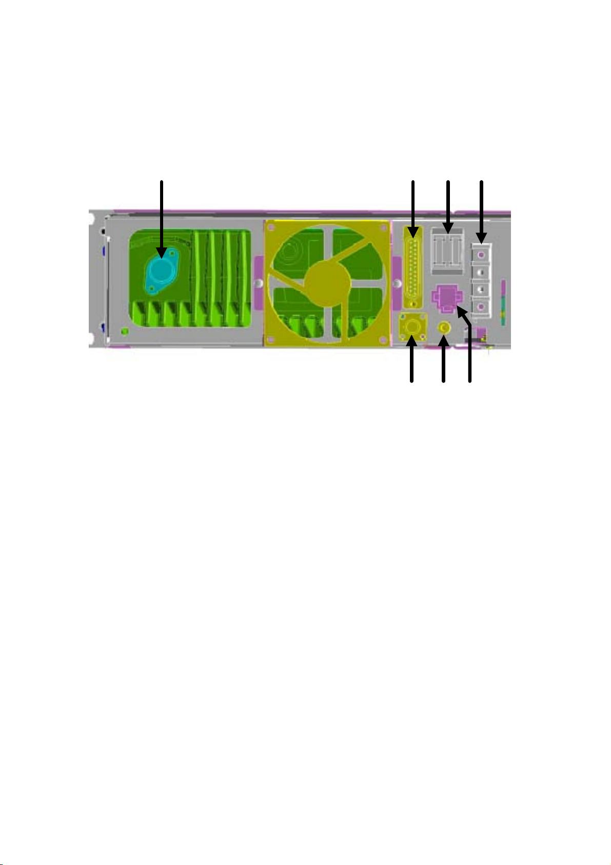
(1) Antenna Connector for Transmission
The 50-ohm coaxial feedline to the antenna for transmission must be connected here, using Type-N
coaxial connector.
(2) DSUB 25-pin Accessory Connector
DB-25 connector allows the repeater to be remote-controlled by external controller. Analog signals,
such as TX_AF_IN, DISC_OUT, RSSI, and so on, are input and output. Furthermore, this repeater
has eight port programmable input/output feature (PIO) for various control (or being controlled).
Each port can be programmed their function, input or output, and its logic (output only).
(3) Antenna Connector for Reception
The 50-ohm coaxial feedline to the antenna for reception must be connected here, using Type-BNC
coaxial connector.
(4) Main Power Source Connector
A power supply for main power source should be connected here.
3/13
Vertex Standard Co., Ltd.

FCC ID: K66VXR-9000U
Operating Manual
(5) Backup Power Source Terminals
A power supply for backup power source, such as rechargeable battery should be connected here.
When the repeater is working by main power source, a trickle charge current is present here.
(6) Circuit Protection Fuse
Two 15A blade fuses for main and backup power source.
(7) External Speaker Jack
3.5 mm 2-pin extenal speaker jack. Recommanded load impedance is from 4 ohm to 16 ohm. The
output level varies in accordance with the position of volume knob on the front panel.
4/13
Vertex Standard Co., Ltd.
 Loading...