


Operating Manual

CONTENTS
Important Notice! .............................................. 1
Introduction.......................................................2
Controls & Connectors ..................................... 3
Top Panel ....................................................................3
LCD Display...............................................................4
Front Panel ..................................................................5
Keypad ........................................................................6
Left Side ......................................................................7
Right Side ...................................................................8
Before You Begin .............................................. 9
Precaution ...................................................................9
Battery Installation and Removal ..............................9
Battery Charging.......................................................10
Low Battery Indication ............................................11
Installing the FBA-25 (option)
Alkaline Battery Case.........................................11
Operation......................................................... 12
Preliminary Steps......................................................12
Operation Quick Start ..............................................12
Accessing the 121.5 MHz
Emergency Frequency..............................................14
Tuning Methods........................................................15
NOTICE
There are no user-serviceable points inside this transceiver.
All service jobs must be referred to your Authorized Service Center.
Transmission ............................................................ 16
Reception of Weather Channel Broadcasts ............ 16
Monitor Key............................................................. 18
ANL (Automatic Noise Limiter) Feature ............... 18
LOCK Function ....................................................... 19
Beep On/Off............................................................. 19
Receive Battery Saver Setup................................... 20
Memory Operation........................................... 21
Memory Storage ...................................................... 21
Recalling the Memories .......................................... 22
Scanning Operation ........................................ 23
Channel-Skip Scanning ........................................... 24
Dual Watch Operation ..................................... 25
Priority Dual Watch Operation ........................ 26
Split Operation ................................................ 27
Programming a Transmit Frequency ...................... 27
Operating in the Split Mode.................................... 27
Field Programming Mode................................ 28
Memory Storage into the Book Memory ............... 28
Menu (“Set”) Mode.......................................... 29
Menu Listing ............................................................ 30
Specifications.................................................. 33
Accessories & Options ................................... 34

IMPORTANT NOTICE!
FCC RF Exposure Compliance Requirements for Occupational Use Only:
This Radio has been tested and complies with the Federal Communications Commission (FCC) RF exposure
limits for Occupational Use/Controlled exposure environment. In addition, it complies with the following Standards and Guidelines:
FCC 96-326, Guidelines for Evaluating the Environmental Effects of Radio-Frequency Radiation.
r
FCC OET Bulletin 65 Edition 97-01 (1997) Supplement C, Evaluating Compliance with FCC Guidelines
r
for Human Exposure to Radio Frequency Electromagnetic Fields.
ANSI/IEEE C95.1-1992, IEEE Standard for Safety Levels with Respect to Human Exposure to Radio
r
Frequency Electromagnetic Fields, 3 kHz to 300 GHz.
ANSI/IEEE C95.3-1992, IEEE Recommended Practice for the Measurement of Potentially Hazardous Elec-
r
tromagnetic Fields - RF and Microwave.
This radio is NOT approved for use by the general population in an uncontrolled environment. This
¦
radio is restricted to occupational use, work related operations only where the radio operator must
have the knowledge to control its RF exposure conditions.
When transmitting, hold the radio in a vertical position with its microphone 1 to 2 inches (2.5 to 5 cm)
¦
away from your mouth and keep the antenna at least 1 inch (2.5 cm) away from your head and body.
The radio must be used with a maximum operating duty cycle not exceeding 50%, in typical Push-to-
¦
Talk configurations.
DO NOT transmit for more than 50% of total radio use time (50% duty cycle). Transmitting more
than 50% of the time can cause FCC RF exposure compliance requirements to be exceeded.
The radio is transmitting when the red LED on the top of the radio is illuminated. You can cause the
radio to transmit by pressing the P-T-T button.
Always use Vertex Standard authorized accessories.
¦
VXA-200 AVIATOR PILOT II OPERATING MANUAL
1

INTRODUCTION
The Yaesu VXA-200 Aviator Pilot II is a compact, stylish, solid hand-held transceiver providing communica-
tion (transmit and receive) capability on the International Aircraft Communication Band (“
136.975 MHz), and it additionally provides VOR and CDI navigation features on the “
117.975 MHz).
The VXA-200 includes Temperature display with our exclusive Omni-GlowTM display back-light for minimal
degradation of your night vision, NOAA weather band monitoring, 8-character Alpha/Numeric Display, 50
Memory Channels, and 100 “Book Memory” Channels. And the optional Barometric Pressure Unit (SU-1)
provides readout of barometric pressure, altitude, and density altitude.
We recommend that you read this manual in its entirety, so as to understand the many features of the VXA-200
completely. Keep this manual handy, so you may use it for reference.
NOTE: The VXA-200’s VOR and CDI Navigation features are supplemental aids to navigation only, and are
not intended to be a substitute for accurate (primary) VOR/CDI or landing service equipment. And also, the
Barometric/Altitude features of the optional SU-1 are designed to be a substitute for accurate, calibrated Barometer or Altimeter devices used for navigation critical to personal safety.
Congratulations!
You now have at your fingertips a valuable communications tool-a YAESU two-way radio! Rugged,
reliable and easy to use, your YAESU radio will keep you in constant touch with your colleagues for
years to come, with negligible maintenance down-time.
COM
” band: 118 ~
NAV
” band (108 ~
Please take a few minutes to read this manual carefully. The information presented here will allow you to
derive maximum performance from your radio, in case questions arise later on.
We're glad you joined the YAESU team. Call on us anytime, because communications is our business.
Let us help you get your message across.
2
VXA-200 AVIATOR PILOT II OPERATING MANUAL
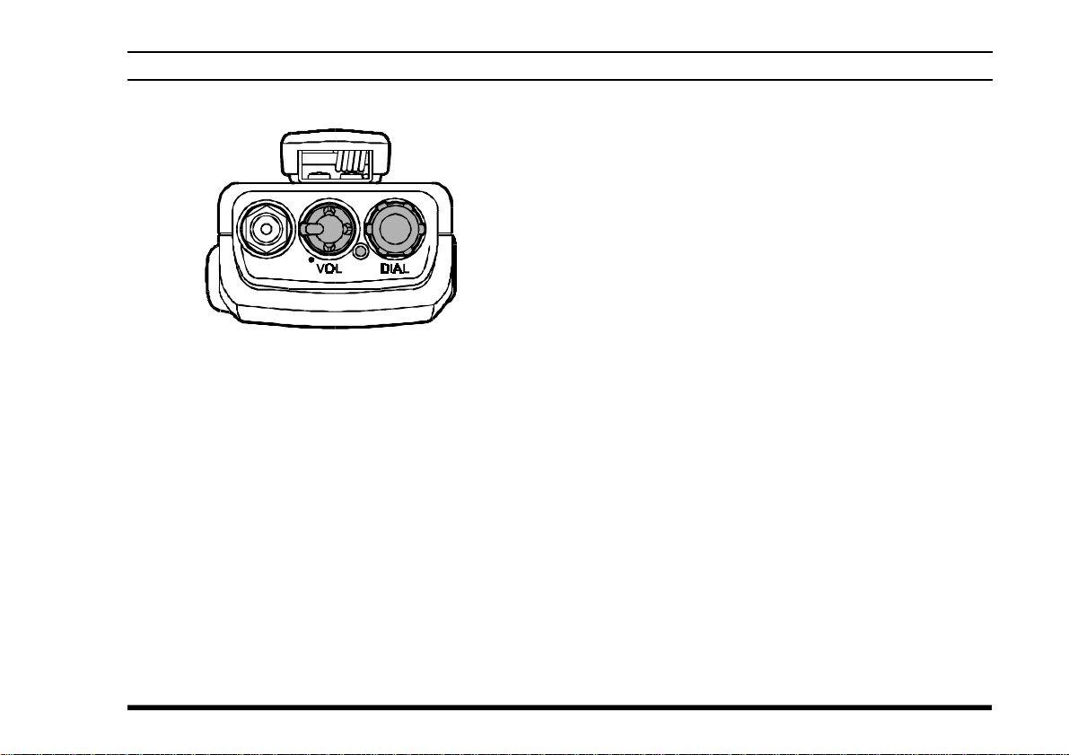
CONTROLS & CONNECTORS (TOP PANEL
① Antenna Jack
This SMA jack accepts the supplied flexible antenna, or another antenna designed to provide 50
Ω impedance on the Aircraft Communication
Band.
② POWER/VOLUME Knob
Turn this control clockwise to turn the radio on
and to increase the volume. Counterclockwise rotation into the click-stop will turn the radio off.
)
③ CHANNEL Selector Knob
This 20-position detended rotary switch tunes the
operating frequency or selects the memory channels.
Pressing this knob momentarily selects the tuning methods among the VFO (Variable Frequency Oscillator), MR (Memory Recall),
BOOK (Pre-Programmed Memories), and WX
(Weather Channel Memories) mode.
Note: The WX mode is activating the USA version only.
④ BUSY/TX Indicator Lamp
This lamp glows green when a signal is being
received and red when transmitting.
VXA-200 AVIATOR PILOT II OPERATING MANUAL
3
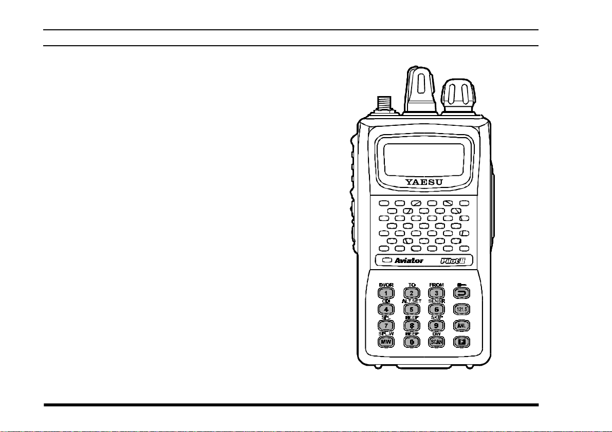
CONTROLS & CONNECTORS (FRONT PANEL
⑤ LCD (Liquid Crystal Display)
The display shows the selected operating conditions as indicated on the next page.
⑥ Loudspeaker
The internal speaker is located in this position.
⑦ Microphone
Speak across this opening in a normal voice level
while pressing the PTT switch.
⑧ Keypad
Several keys have dual functions.
The primary functions are labeled on the key top
(activated by simply pressing the key momentarily), while the secondary functions are labeled
to along with the top edge of the key (activated
by pressing the [F] key first, then the indicated
key).
These functions are described in detail on page 5.
⑨ Battery Pack Latch
Open this latch for battery removal.
)
4
VXA-200 AVIATOR PILOT II OPERATING MANUAL
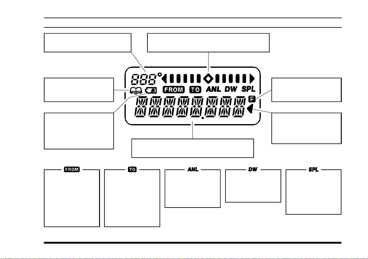
CONTROLS & CONNECTORS (LCD DISPLAY
)
This field displays the course
heading in degrees. See page 25.
This icon indicates that
the “Book” Memory Bank
is in use. See page 12.
This icon is the “Low Battery” indicator, which
blinks when the battery
voltage becomes too low
for proper operation.
This icon is used
during VOR navigation, to indicate that
the displayed information is based on
a course from the
VOR station. See
page 25.
This icon is used
during VOR navigation, to indicate that
the displayed information is based on
a course to the VOR
station. See page
25.
This is the Course Deviation Indicator, used
during VOR Navigation. See page 24.
These digits provide frequency or alphanumeric
information about the channel you are using.
This indicator confirms that the AUTO-
MATIC NOISE LIMITER is
activated. See page
15.
This indicator confirms that DUAL
WATCH is active. See
page 22.
This indicator confirms
that Secondary Key Function is active. See page 4.
This indicator confirms
that this channel will be
skipped during scan. See
page 21.
This indicator confirms that the “Split”
(Duplex) mode is
activated during
VOR operation. See
page 30.
VXA-200 AVIATOR PILOT II OPERATING MANUAL
5
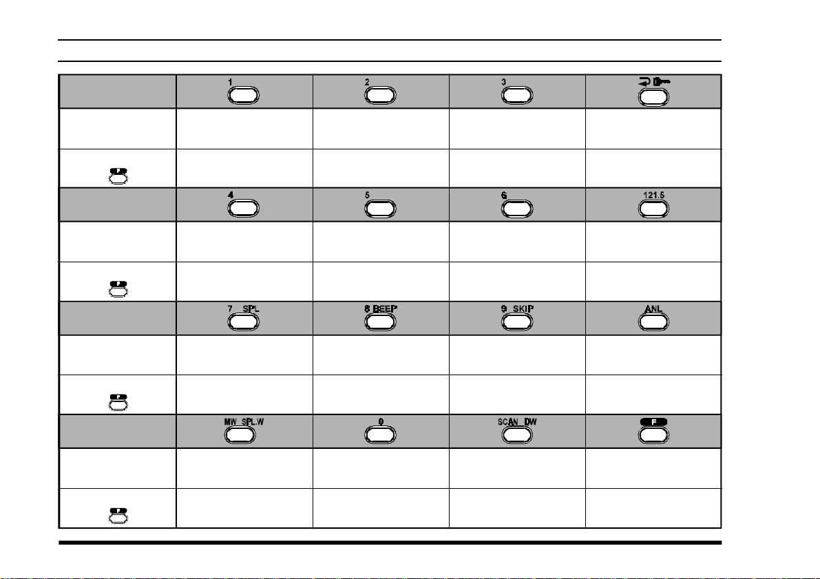
CONTROLS & CONNECTORS (KEYPAD
)
Primary Function
(
Press Key
Secondary Function
(
Press +
Primary Function
(
Press Key
Secondary Function
(
Press +
Primary Function
(
Press Key
Secondary Function
(
Press +
Primary Function
(
Press Key
Secondary Function
(
Press +
)
)
)
)
)
)
)
)
Frequency Entry
Digit 1
Activates DVOR mode
Frequency Entry
Digit 4
Activates Course
Direction Indicator mode
Frequency Entry
Digit 7
Activates Split (Duplex
mode
Memory “Write”
Command
Split-Memory “Write”
Command
Frequency Entry
Digit 2
Selects
“TO” VOR mode
Frequency Entry
Digit 5
Display the Density
Altitude (requires SU-1)
Frequency Entry
Digit 8
)
On/Off Switch
for Keypad Beeper
Frequency Entry
Digit 0
Frequency Entry
Digit 3
Selects
“FROM” VOR mode
Frequency Entry
Digit 6
Display the current
Temperature
Frequency Entry
Digit 9
Allows Skipping of
Channel during Scan
Activates Scanning
Activates Dual Watch
Selects Memory Display
Type (page 19)
Locks the Keypad
Selects Emergency
Channel (121.5 MHz
None
Activates Automatic
Noise Limiter
None
Activates “Secondary”
Key mode
NoneNone
)
6
VXA-200 AVIATOR PILOT II OPERATING MANUAL
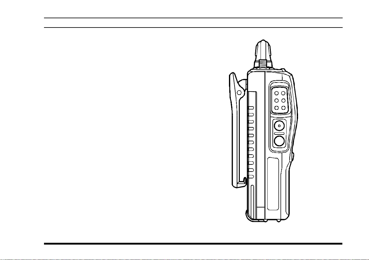
CONTROLS & CONNECTORS (LEFT SIDE
⑩ PTT (PUSH TO TALK) Switch
Press this button to transmit when you are operating in the “
return to the “RECEIVE” mode. See page 15.
⑪ MONITOR Switch
This button may be pressed to “open” the squelch
manually, allowing you to listen for very weak
signals. Press and hold this button for 2 seconds
to “open” the squelch continuously. Press this
button again to resume normal (quiet) monitoring. See page 12.
⑫ LAMP Switch
Press this switch momentarily to activate the
back-lighting lamp for the display. Press and hold
this switch for 2 seconds to activate the backlighting lamp continuously. To turn the lamp off,
press this switch again. The LAMP switch may
be configured in several ways via the Menu; see
page 28 for details.
COM
” band. Release this button to
)
VXA-200 AVIATOR PILOT II OPERATING MANUAL
7
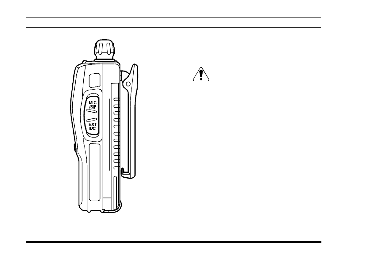
CONTROLS & CONNECTORS (RIGHT SIDE
⑬ MIC/EAR Jack
You may connect the supplied CT-60 Headset
Cable or the (optional) MH-44A4B Speaker/Microphone to this jack.
Never connect any Speaker/Microphone
that is not recommended by the manufacturer. Because these jack connections are unique,
using a Speaker/Microphone that is not specified
by Yaesu may damage the VXA-200.
⑭ EXT DC Jack
When an external 12-Volt DC power source is
available, you may connect the (optional) E-DC-
5B External DC Cable here. Do not connect any
wire to this jack if that wire is connected directly to a 28-Volt DC source. Connecting the
VXA-200 directly to a source which exceeds 15.0
Volts DC will result in damage to the unit.
)
8
VXA-200 AVIATOR PILOT II OPERATING MANUAL
BEFORE YOU BEGIN
Precautions
r This apparatus is capable of two-way communi-
cation on channels used for critical aviation safety
communications. Therefore, it is important that
this radio be kept away from children or other
unauthorized users at all times.
r When making DC connections via the (optional)
E-DC-5B DC cable, be absolutely certain to
observe the proper voltage level and polarity
guidelines. Do not connect this radio directly to
any 24 ~ 28 Volt DC source, nor to AC power of
any kind. Connecting the VXA-200 directly to a
source which exceeds 15.0 Volts DC will result
in damage to the unit.
r Do not dispose of the Ni-Cd Battery Pack in a
fire. Do not carry a Ni-Cd Battery Pack in your
pocket, where keys or coins could short the terminals. This could create a serious fire/burn danger, and possibly cause damage to the Ni-Cd
pack.
r Although the VXA-200 is designed to be water
resistant, the enclosure is not “waterproof.” Do
not allow the radio to become submersed in water, and do not expose it and/or its Ni-Cd Battery
Pack to water spray under pressure.
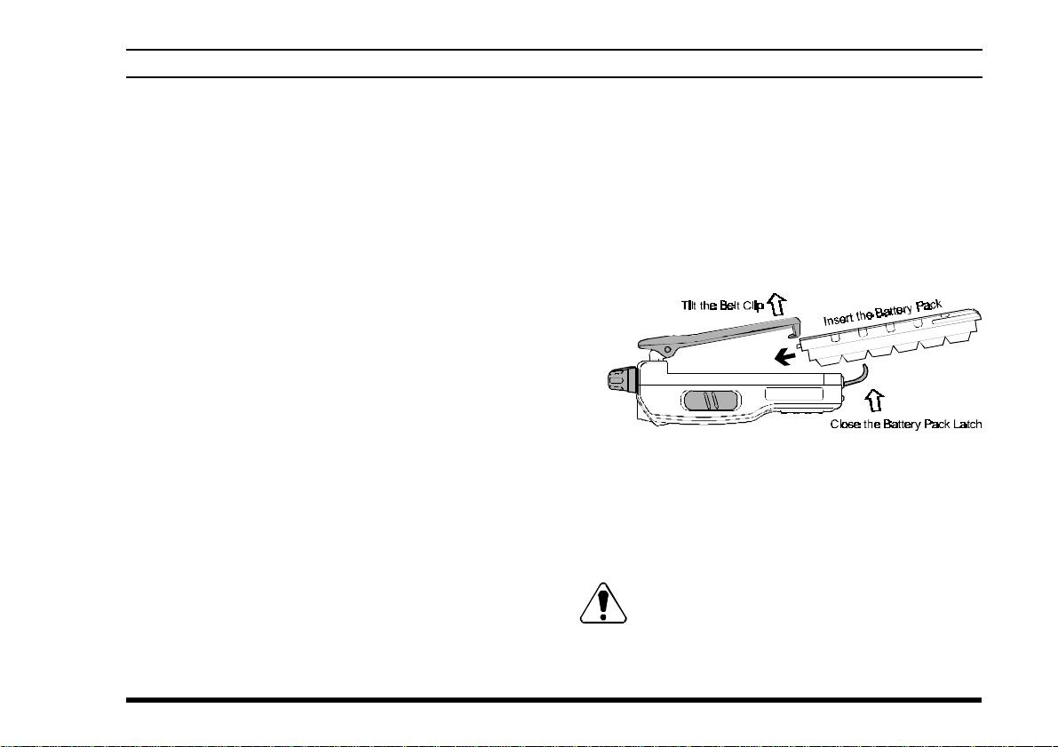
Battery Installation and Removal
¦ To install the battery, hold the transceiver with
your left hand, so your palm is over the speaker
and your thumb is on the top of the Belt Clip.
Insert the battery pack into the battery compartment on the back of the radio while tilting the
Belt Clip outward, then close the Battery Pack
Latch until it locks in place with a “Click.”
¦ To remove the battery, turn the radio off and re-
move any protective cases. Open the Battery Pack
Latch on the bottom of the radio, then slide the
battery downward and out from the radio while
unfolding the Belt Clip.
Do not attempt to open any of the recharge-
able Ni-Cd packs, as personal injury or damage to the Ni-Cd pack could occur if a cell or cells
become accidentally short-circuited.
VXA-200 AVIATOR PILOT II OPERATING MANUAL
9
BEFORE YOU BEGIN
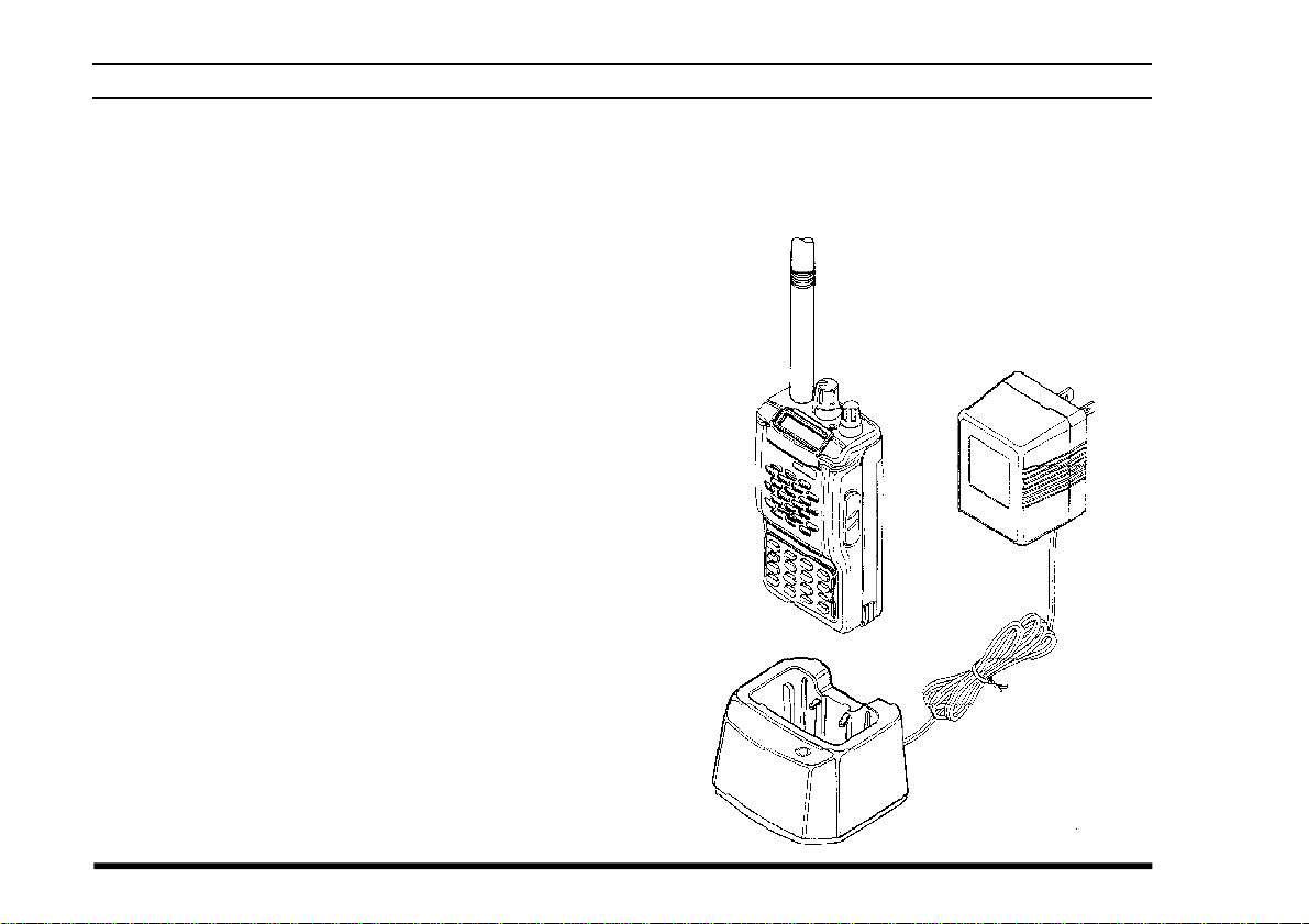
Battery Charging
It is necessary to fully charge the Ni-Cd battery before its first use. Follow these procedures:
¦ Install the supplied FNB-64 Ni-Cd battery pack
onto the transceiver. Ensure that the transceiver
is switched off.
¦ Plug the NC-77 into the AC line outlet.
¦ Insert the battery pack into the NC-77; the an-
tenna jack should be at the left side when viewing the charger from the front.
¦ If the battery pack is inserted correctly, the RED
indicator will glow. A fully-discharged pack will
be charged completely in 15 hours.
Important Notes:
r The NC-77 is not designed to power the trans-
ceiver for operation (reception or transmission).
r Do not leave the charger connected to the trans-
ceiver for continuous periods in excess of 24
hours. Long term overcharging can degrade the
Ni-Cd battery pack and significantly shorten its
useful life.
r If using a charger other than the NC-77, or if
using a battery pack other than the FNB-64, follow the appropriate instructions provided with
the charger/battery. Contact your Dealer if you
have any doubts about the appropriateness of the
particular charger or battery pack you intend to
use.
VXA-200/NC-77
10
VXA-200 AVIATOR PILOT II OPERATING MANUAL

BEFORE YOU BEGIN
Low Battery Indication
¦ As your battery discharges during use, the volt-
age will gradually become lower. When the battery voltage reaches 6.0 Volts, the “x ” icon
will blink on the LCD display, indicating that
the battery pack must be recharged before further use.
¦ Avoid recharging Ni-Cd batteries before the
“Low Battery” indicator is observed, as this can
degrade the charge capacity of your Ni-Cd battery pack. Yaesu recommends that you carry an
extra, fully-charged pack with you so you will
not lose communications capability due to a depleted Ni-Cd battery.
This “deep cycling” practice will help to maintain longer overall battery life after many recharging cycles.
Installing the FBA-25 (option) Alkaline
Battery Case
The optional FBA-25 Battery Case allows operation of the VXA-200 using six “AA” size Alkaline
batteries.
When installing batteries, insert the (–) end first, then
press in the (+) end so the battery snaps into place.
Always replace all six batteries at the same time, paying attention to the polarity indicated inside the case.
The FBA-25 must not be used with re-
chargeable cells. The FBA-25 does not contain the thermal and over-current protection circuits (provided in the “FNB” series of Ni-Cd Battery Packs) required when utilizing Ni-Cd cells.
VXA-200 AVIATOR PILOT II OPERATING MANUAL
11
OPERATION
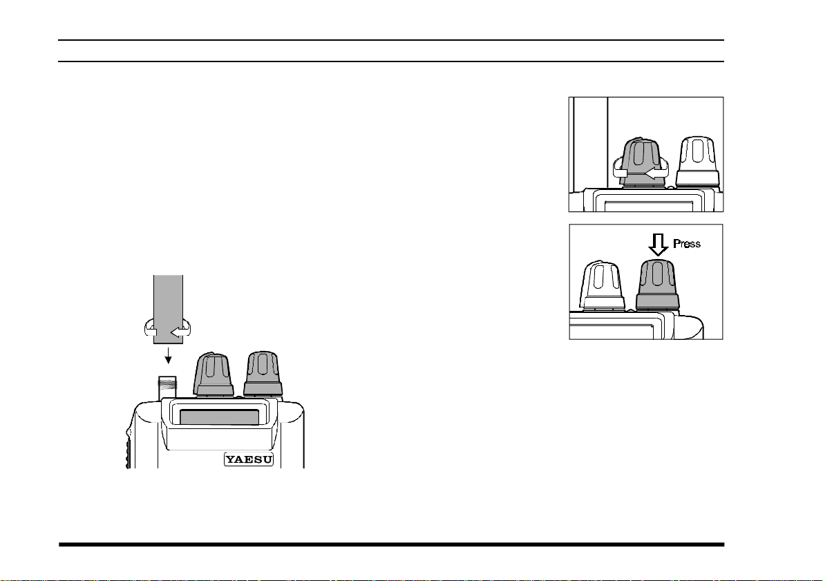
Preliminary Steps
¦ Install a charged battery pack onto the transceiver,
as described previously.
¦ Screw the supplied antenna onto the Antenna
jack. Never operate this transceiver without an
antenna connected.
¦ If you have an optional Speaker/Microphone or
headset, we recommend that it not be connected
until you are familiar with the basic operation of
the VXA-200.
Operation Quick Start
r To turn the radio on,
rotate the VOLUME
knob out of the clickstop.
r After three “initial-
ization” beeps are
heard, a channel frequency should appear on the display. If
not, press downward
(momentarily) on the
CHANNEL selector knob (repeatedly, if neces-
sary) so that “
followed by a channel frequency.
r Directly entering frequencies from the Keypad
is the easiest method if you know the frequency
on which you wish to operate. Just enter the five
digits of the frequency to move to that frequency.
For example, to set 134.35 MHz,
press [1] à [3] à [4] à [3] à [5].
" VFO "
” appears on the display,
12
VXA-200 AVIATOR PILOT II OPERATING MANUAL
OPERATION
To set 118.275 MHz, you do not need to press
the final “5” in the frequency:
[1]
à [1] à [8] à [2] à [7].
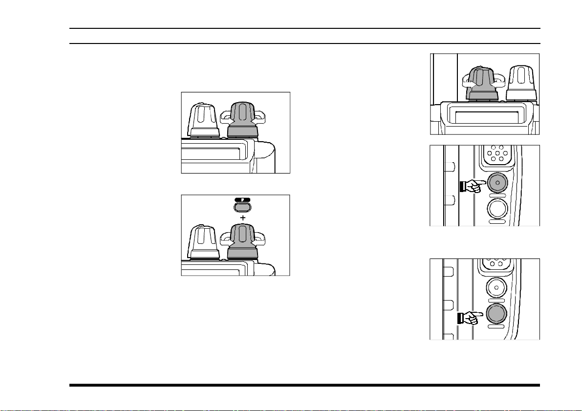
r You may also turn
the top panel’s
CHANNEL selector
knob to choose the
desired operating frequency. The channel
frequency will appear on the LCD.
r To change frequency
in 1 MHz steps, press
the [F] key momentarily, then rotate the
CHANNEL selector
knob to select the
MHz digit desired.
Press [F] once more to resume normal channel
selection in 25-kHz steps.
r Rotate the VOL-
UME knob to set the
volume level. If no
signal is present,
press and hold the
MONITOR button
for 2 seconds; background noise will
now be heard, and
you may use this
noise to set the VOL-
UME knob for the
desired audio level.
Press the MONITOR
button momentarily to silence the noise and resume normal (quiet) monitoring.
r Press and hold the
LAMP button for 2
seconds, to illuminate the display continuously. To disable
the illumination,
press the LAMP button momentarily.
VXA-200 AVIATOR PILOT II OPERATING MANUAL
13
 Loading...