

HEAVY DUTY AIR BAND TRANSCEIVER
VXA-150
Operating Manual

CONTENTS
Important Notice! ................................................ 1
Introduction ......................................................... 2
Accessories & Options....................................... 3
Controls & Connectors....................................... 4
Top Panel ................................................................ 4
LCD Display ........................................................... 5
Front Panel .............................................................. 6
Keypad .................................................................... 7
Left Side .................................................................. 8
Right Side................................................................ 9
Before You Begin .............................................. 10
Precaution.............................................................. 10
Battery Installation and Removal .......................... 10
Battery Charging ................................................... 11
Low Battery Indication.......................................... 12
Installing the FBA-25 (option)
Alkaline Battery Case ...................................... 12
Operation ........................................................... 13
Preliminary Steps .................................................. 13
Operation Quick Start............................................ 13
Accessing the 121.5 MHz
Emergency Frequency ........................................... 15
Tuning Methods .................................................... 16
NOTICE
There are no user-serviceable points inside this transceiver.
All service jobs must be referred to your Authorized Service Center.
Transmission ......................................................... 17
Reception of Weather Channel Broadcasts............ 17
Monitor Key .......................................................... 19
ANL (Automatic Noise Limiter) Feature............... 19
LOCK Function..................................................... 20
Beep On/Off .......................................................... 20
Receive Battery Saver Setup ................................. 21
Memory Operation ............................................ 22
Memory Storage .................................................... 22
Recalling the Memories......................................... 23
Scanning Operation .......................................... 24
Channel-Skip Scanning ......................................... 25
Dual Watch Operation....................................... 26
Priority Dual Watch Operation ......................... 27
Split Operation .................................................. 28
Programming a Transmit Frequency...................... 28
Operating in the Split Mode .................................. 28
Field Programming Mode................................. 29
Memory Storage into the Book Memory ............... 29
Menu (“Set”) Mode ........................................... 30
Menu Listing ......................................................... 31
Specifications.................................................... 34
VXA-150 AVIATOR PROV OPERATING MANUAL

IMPORTANT NOTICE!
FCC RF Exposure Compliance Requirements for Occupational Use Only:
This Radio has been tested and complies with the Federal Communications Commission (FCC) RF exposure
limits for Occupational Use/Controlled exposure environment. In addition, it complies with the following
Standards and Guidelines:
FCC 96-326, Guidelines for Evaluating the Environmental Effects of Radio-Frequency Radiation.
r
FCC OET Bulletin 65 Edition 97-01 (1997) Supplement C, Evaluating Compliance with FCC Guidelines
r
for Human Exposure to Radio Frequency Electromagnetic Fields.
ANSI/IEEE C95.1-1992, IEEE Standard for Safety Levels with Respect to Human Exposure to Radio
r
Frequency Electromagnetic Fields, 3 kHz to 300 GHz.
ANSI/IEEE C95.3-1992, IEEE Recommended Practice for the Measurement of Potentially Hazardous Elec-
r
tromagnetic Fields - RF and Microwave.
This radio is NOT approved for use by the general population in an uncontrolled environment. This
¦
radio is restricted to occupational use, work related operations only where the radio operator must
have the knowledge to control its RF exposure conditions.
When transmitting, hold the radio in a vertical position with its microphone 1 to 2 inches (2.5 to 5
¦
cm) away from your mouth and keep the antenna at least 1 inch (2.5 cm) away from your head and
body.
The radio must be used with a maximum operating duty cycle not exceeding 50%, in typical Push-to-
¦
Talk configurations.
DO NOT transmit for more than 50% of total radio use time (50% duty cycle). Transmitting more
than 50% of the time can cause FCC RF exposure compliance requirements to be exceeded.
The radio is transmitting when the red LED on the top of the radio is illuminated. You can cause the
radio to transmit by pressing the P-T-T button.
Always use Vertex Standard authorized accessories.
¦
VXA-150 AVIATOR PROV OPERATING MANUAL
1

INTRODUCTION
The Vertex Standard VXA-150 Aviator Pr oV is a compact, stylish, solid hand-held transceiver providing
communication (transmit and receive) capability on the International Aircraft Communication Band (“COM”
band: 118 ~ 136.975 MHz), and it additionally provides receive on the “NAV” band (108 ~ 117.975 MHz).
The VXA-150 includes our exclusive two-mode display with upright or inverted viewing when on your belt,
NOAA weather band monitoring, 8-character Alpha/Numeric Display, 50 Memory Channels, and 100 “Book
Memory” Channels.
We recommend that you read this manual in its entirety, so as to understand the many features of the VXA-150
completely. Keep this manual handy, so you may use it for reference.
Congratulations!
You now have at your fingertips a valuable communications tool-a Vertex Standard two-way radio!
Rugged, reliable and easy to use, your Vertex Standard radio will keep you in constant touch with your
colleagues for years to come, with negligible maintenance down-time.
Please take a few minutes to read this manual carefully. The information presented here will allow you to
derive maximum performance from your radio, in case questions arise later on.
We’re glad you joined the Vertex Standard team. Call on us anytime, because communications is our
business. Let us help you get your message across.
2
VXA-150 AVIATOR PROV OPERATING MANUAL

ACCESSORIES & OPTIONS
Supplied Accessories
Ni-Cd Battery Pack (7.2V, 700mAh)FNB-64
Overnight Desktop Charger NC-72B/C/U
Helical Antenna ATV-7
Headset Cable CT-60
Operating Manual
Warranty Card
:
ø
“B” suffix is for use with 117 VAC,
“C” suffix is for use with 220-240 VAC, or
“U” suffix is for use with 230 VAC.
Availability of accessories may vary. Some accessories are supplied as standard per local requirements, while
others may be unavailable in some regions. Consult your Vertex Standard Dealer for details regarding these
and any newly-available options.
Connection of any non-Vertex Standard-approved accessory, should it cause damage, may void the Limited
Warranty on this apparatus.
ø
Available Options
MH-44A4B Speaker Microphone
FNB-V57 Ni-Cd Battery Pack (7.2V, 1100mAh)
FBA-25 Alkaline Battery Case
VAC-400 Desktop Rapid Charger
E-DC-5B External Power Cable
CN-3 Antenna Adapter
VXA-150 AVIATOR PROV OPERATING MANUAL
3
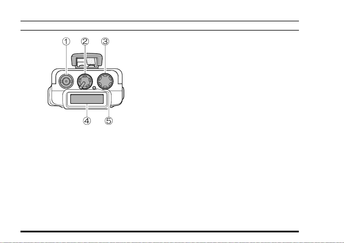
CONTROLS & CONNECTORS (TOP PANEL
① Antenna Jack
This SMA jack accepts the supplied flexible antenna, or another antenna designed to provide 50
W impedance on the Aircraft Communication
Band.
② POWER/VOLUME Knob
Turn this control clockwise to turn the radio on
and to increase the volume. Counterclockwise rotation into the click-stop will turn the radio off.
)
③ CHANNEL Selector Knob
This 20-position detended rotary switch tunes the
operating frequency or selects the memory channels.
Pressing this knob momentarily selects the tuning methods among the VFO (Variable Frequency Oscillator), MR (Memory Recall),
BOOK (Pre-Programmed Memories), and WX
(Weather Channel Memories) mode.
Note: The WX mode is activating the USA version only.
④ LCD (Liquid Crystal Display)
The display shows the selected operating conditions as indicated on the next page.
The display may be changed to “inverted” viewing via the Menu; see page 31 for details.
⑤ BUSY/TX Indicator Lamp
This lamp glows green when a signal is being
received and red when transmitting.
4
VXA-150 AVIATOR PROV OPERATING MANUAL
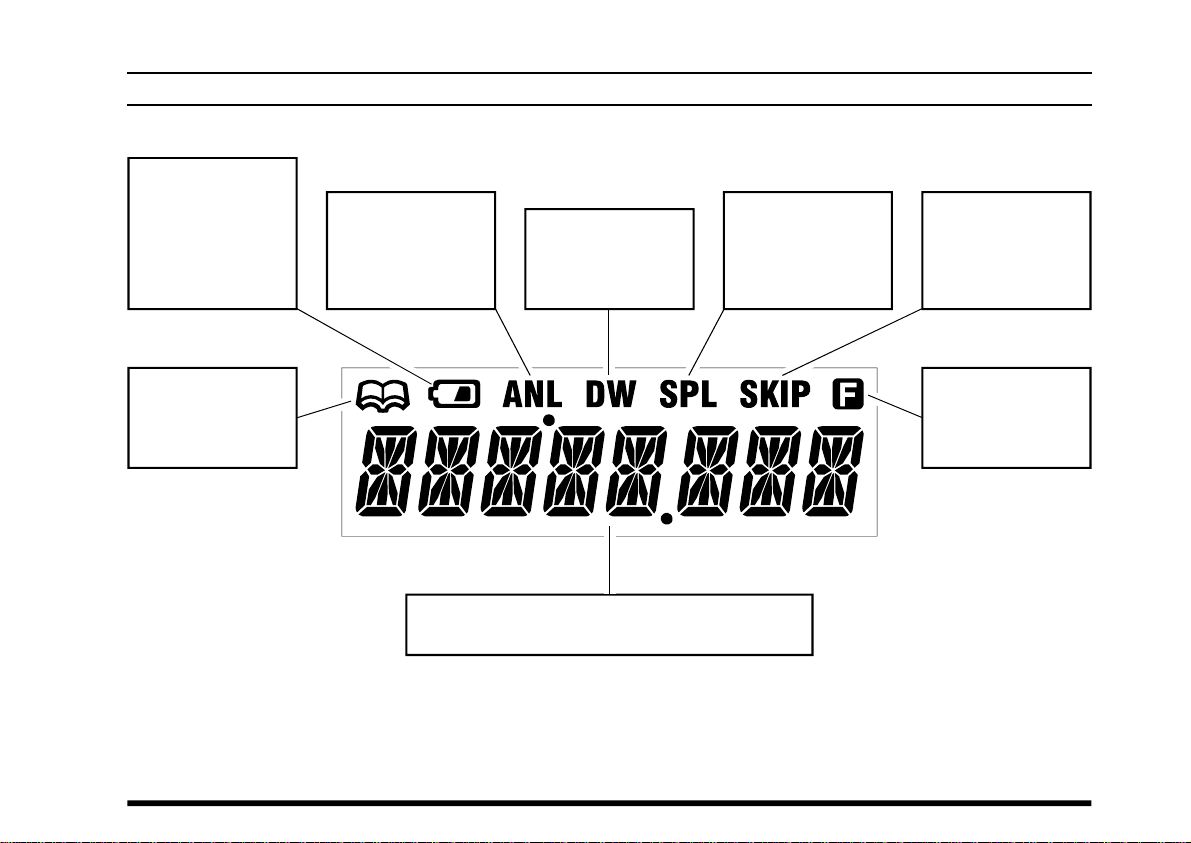
This icon is the
“Low Battery” indicator, which blinks
when the battery
voltage becomes
too low for proper
operation.
CONTROLS & CONNECTORS (LCD DISPLAY
This indicator confirms that the AUTO-
MATIC NOISE LIMITER
is activated. See
page 19.
This indicator confirms that DUAL
WATCH is active.
See page 26.
This indicator confirms that the “Split”
(Duplex) mode is
activated. See
page 28.
)
This indicator confirms that this
channel will be
skipped during
scan. See page 25.
This icon indicates
that the “Book”
Memory Bank is in
use. See page 16.
These digits provide frequency or alphanumeric
information about the channel you are using.
VXA-150 AVIATOR PROV OPERATING MANUAL
This indicator confirms that Second-
ary Key Function is
active. See page 7.
5
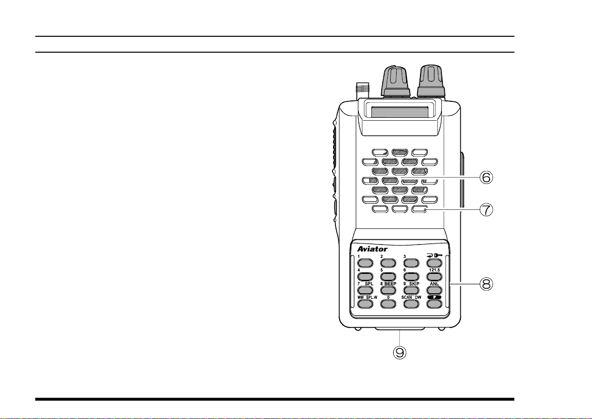
CONTROLS & CONNECTORS (FRONT PANEL
⑥ Loudspeaker
The internal speaker is located in this position.
⑦ Microphone
Speak across this opening in a normal voice level
while pressing the PTT switch.
⑧ Keypad
Several keys have dual functions. The color of
the label determines the way in which you activate the function:
The white labels represent the primary functions
of the keys (activated by simply pressing the key
momentarily).
The yellow labels represent the secondary functions of the keys (activated by pressing the [F
key first, then the indicated key).
On the keypad, primary functions (white) are labeled to the left, while the secondary functions
(yellow) are labeled to the right. These functions
are described in detail on the next page.
)
]
⑨ Battery Pack Latch
Open this latch for battery removal.
6
VXA-150 AVIATOR PROV OPERATING MANUAL
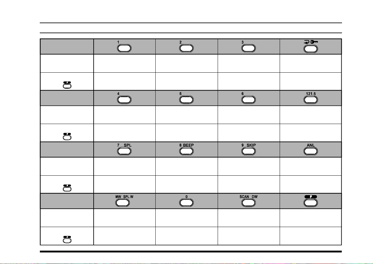
CONTROLS & CONNECTORS (KEYPAD
)
Primary Function
(
Press Key
Secondary Function
(
Press +
Primary Function
(
Press Key
Secondary Function
(
Press +
Primary Function
(
Press Key
Secondary Function
(
Press +
Primary Function
(
Press Key
Secondary Function
(
Press +
)
)
)
)
)
)
)
)
Frequency Entry
Digit 1
Frequency Entry
Digit 4
None
Frequency Entry
Digit 7
Activates Split (Duplex
mode
Memory “Write”
Command
Split-Memory “Write”
Command
Frequency Entry
Digit 2
Frequency Entry
Digit 5
None None None
Frequency Entry
Digit 8
)
On/Off Switch
for Keypad Beeper
Frequency Entry
Digit 0
Frequency Entry
Digit 3
NoneNoneNone
Frequency Entry
Digit 6
Frequency Entry
Digit 9
Allows Skipping of
Channel during Scan
Activates Scanning
Activates Dual Watch
Selects Memory Display
Type (page 19)
Locks the Keypad
Selects Emergency
Channel (121.5 MHz
Activates Automatic
Noise Limiter
None
Activates “Secondary”
Key mode
NoneNone
)
VXA-150 AVIATOR PROV OPERATING MANUAL
7
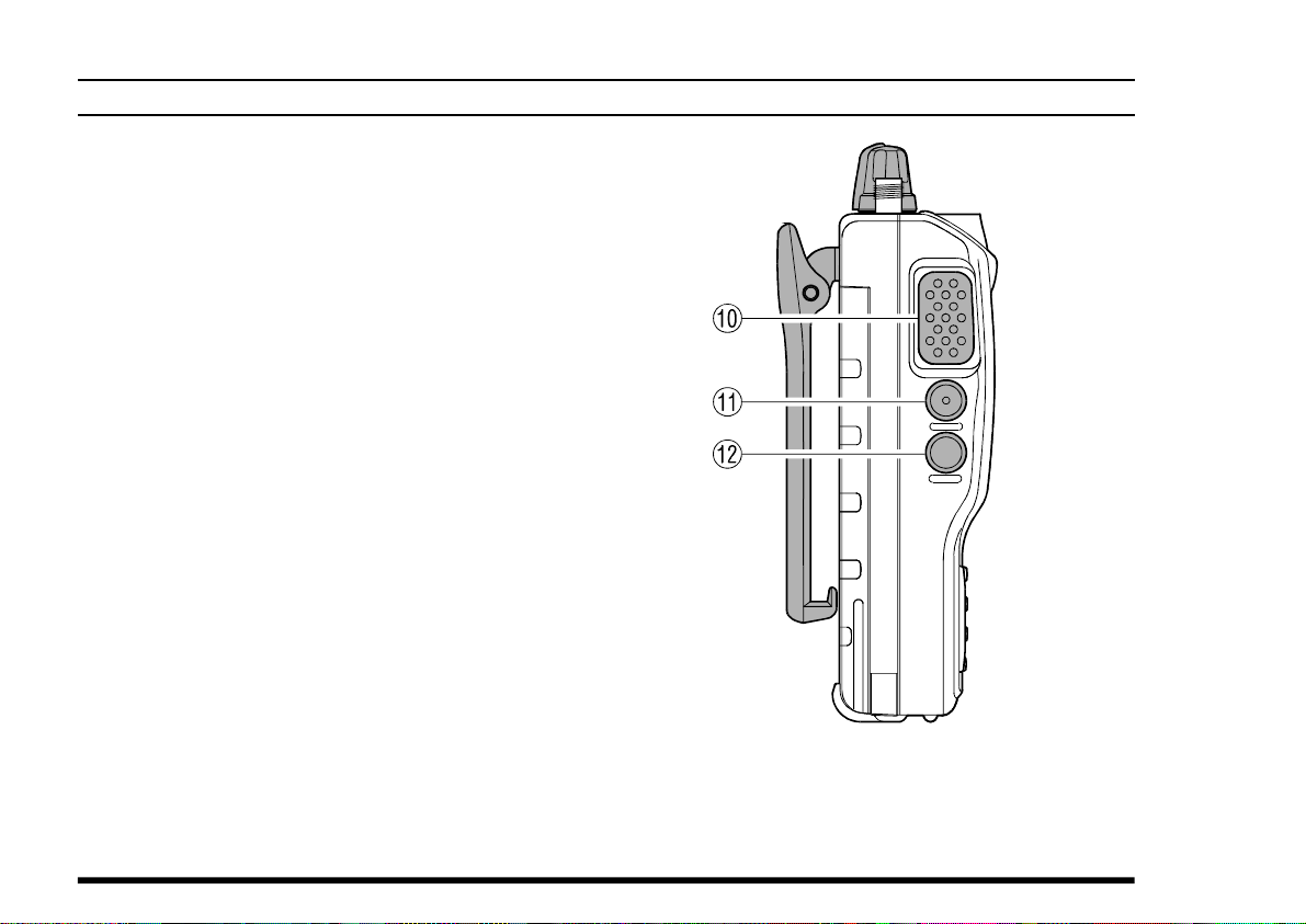
CONTROLS & CONNECTORS (LEFT SIDE
⑩ PTT (PUSH TO TALK) Switch
Press this button to transmit when you are operating in the “COM” band. Release this button to
return to the “RECEIVE” mode. See page 17.
⑪ MONITOR Switch
This button may be pressed to “open” the squelch
manually, allowing you to listen for very weak
signals. Press and hold this button for 2 seconds
to “open” the squelch continuously. Press this
button again to resume normal (quiet) monitoring. See page 14.
⑫ LAMP Switch
Press this switch momentarily to activate the
back-lighting lamp for the display and keypad
keys. Press and hold this switch for 2 seconds to
activate the back-lighting lamp continuously. To
turn the lamp off, press this switch again. The
LAMP switch may be configured in several ways
via the Menu; see page 30 for details.
)
8
VXA-150 AVIATOR PROV OPERATING MANUAL
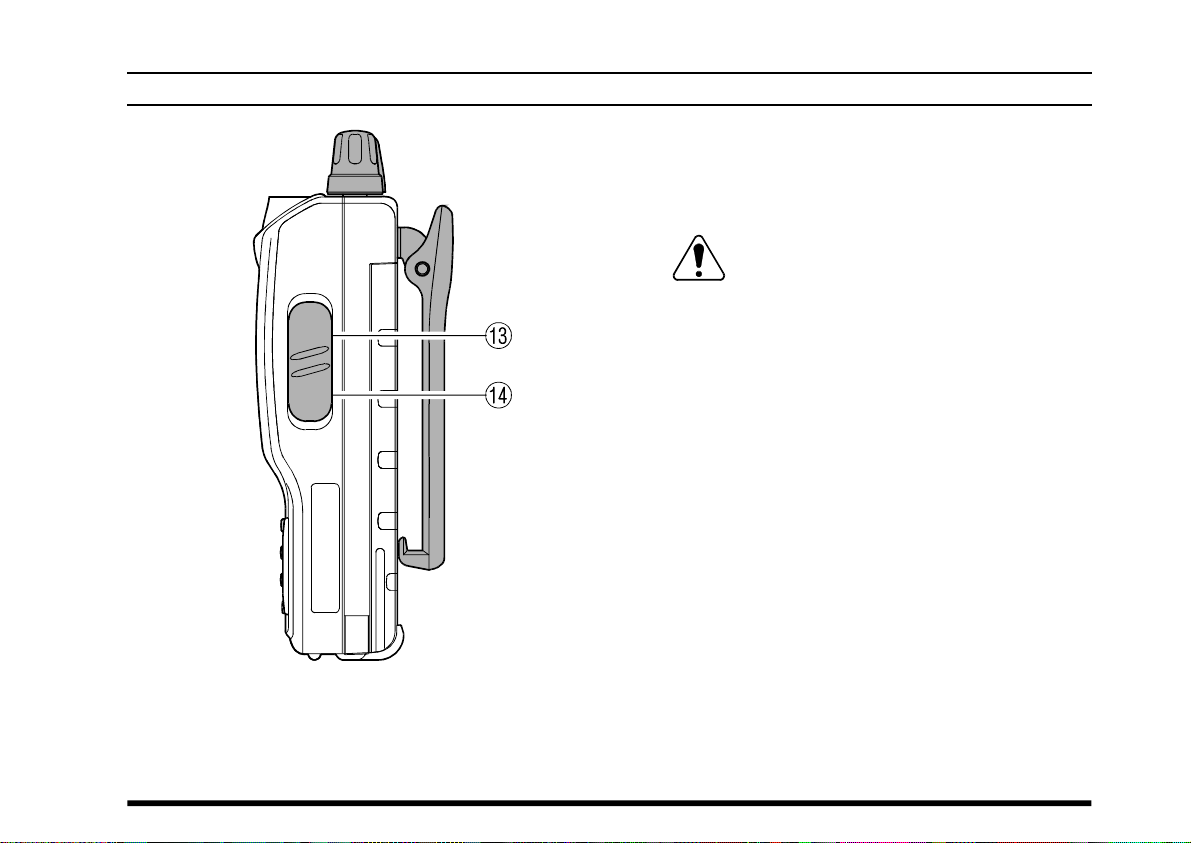
CONTROLS & CONNECTORS (RIGHT SIDE
⑬ MIC/EAR Jack
You may connect the supplied CT-60 Headset
Cable or the (optional) MH-44A4B Speaker/Mi-
crophone to this jack.
Never connect any Speaker/Microphone
that is not recommended by the manufacturer. Because these jack connections are unique,
using a Speaker/Microphone that is not specified
by Vertex Standard may damage the VXA-150.
⑭ EXT DC Jack
When an external 12-Volt DC power source is
available, you may connect the (optional) E-DC-
5B External DC Cable here. Do not connect any
wire to this jack if that wire is connected directly to a 28-Volt DC source. Connecting the
VXA-150 directly to a source which exceeds 15.0
Volts DC will result in damage to the unit.
)
VXA-150 AVIATOR PROV OPERATING MANUAL
9
BEFORE YOU BEGIN
Precautions
r This apparatus is capable of two-way communi-
cation on channels used for critical aviation safety
communications. Therefore, it is important that
this radio be kept away from children or other
unauthorized users at all times.
r When making DC connections via the (optional)
E-DC-5B DC cable, be absolutely certain to
observe the proper voltage level and polarity
guidelines. Do not connect this radio directly to
any 24 ~ 28 Volt DC source, nor to AC power of
any kind. Connecting the VXA-150 directly to a
source which exceeds 15.0 Volts DC will result
in damage to the unit.
r Do not dispose of the Ni-Cd Battery Pack in a
fire. Do not carry a Ni-Cd Battery Pack in your
pocket, where keys or coins could short the terminals. This could create a serious fire/burn danger, and possibly cause damage to the Ni-Cd
pack.
r Although the VXA-150 is designed to be water
resistant, the enclosure is not “waterproof.” Do
not allow the radio to become submersed in water, and do not expose it and/or its Ni-Cd Battery
Pack to water spray under pressure.
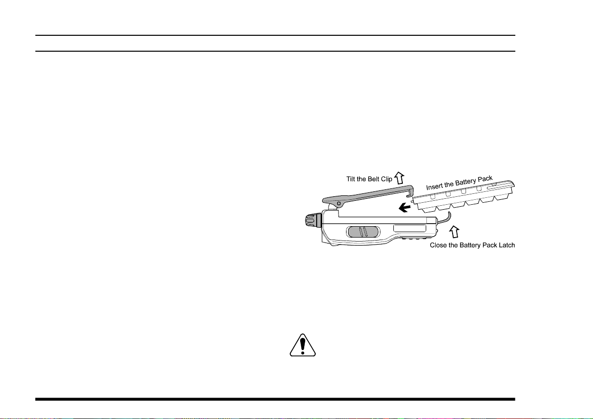
Battery Installation and Removal
¦ To install the battery, hold the transceiver with
your left hand, so your palm is over the speaker
and your thumb is on the top of the Belt Clip.
Insert the battery pack into the battery compartment on the back of the radio while tilting the
Belt Clip outward, then close the Battery Pack
Latch until it locks in place with a “Click.”
¦ To remove the battery, turn the radio off and re-
move any protective cases. Open the Battery Pack
Latch on the bottom of the radio, then slide the
battery downward and out from the radio while
unfolding the Belt Clip.
Do not attempt to open any of the recharge-
able Ni-Cd packs, as personal injury or damage to the Ni-Cd pack could occur if a cell or cells
become accidentally short-circuited.
10
VXA-150 AVIATOR PROV OPERATING MANUAL
 Loading...