

Yaesu Musen VXA 120 Users manual

INTRODUCTION
The Yaesu VXA-120
tion (transmit and receive) capability on the International Aircraft Communication Band (“
136.975 MHz), additionally provides receive on the “
The VXA-120 includes our exclusive two-mode display with upright or inverted for easy viewing when on
your belt, NOAA weather band monitoring capability, 8 character Alpha/Numeric Display, 50 Memory Channels and 100 Book Memory Channels.
We recommend that you read this manual in its entirety, so as to understand the many features of the VXA-120
completely. Keep this manual handy, so you may use it for reference.
Aviator Pro
II is compact, stylish, solid hand-held transceiver providing communica-
COMCOM
COM” band: 118 ~
COMCOM
NAVNAV
NAV” band (108 ~ 117.975 MHz).
NAVNAV
VXA-120 AVIATOR PROII OPERATING MANUAL
1
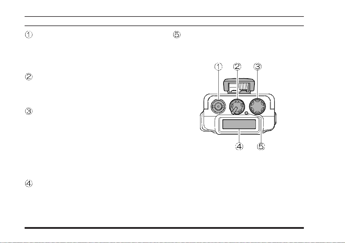
CONTROLS & CONNECTORS (TOP PANEL
)
Antenna Jack
This SMA jack accepts thee supplied flexible
antenna, or another antenna designed to provide
50 Ω impedance on the Aircraft Communication
Band.
POWER/VOLUME Knob
Turn this control clockwise to turn the radio on
and to increase the volume. Counterclockwise rotation into the click-stop will turn the radio off.
CHANNEL Selector Knob
This is 20-position detended rotary switch tunes
the operating frequency or selects the memory
channels.
Pressing this knob momentarily selects the tuning methods among VFO (Variable Frequency
Oscillator), MR (Memory Recall), BOOK (Pre-
Programmed Memories), and WX (Weather
Channel Memories) mode.
LCD (Liquid Crystal Display)
The display shows the selected operating conditions as indicated on the next page.
The display may be changed inverted viewing
via the Menu; see page 29 for details.
BUSY/TX Indicator Lamp
This lamp glows green when a signal is being
received and red when transmitting.
2
VXA-120 AVIATOR PROII OPERATING MANUAL
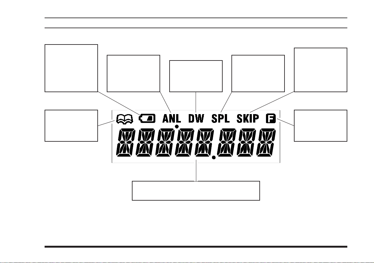
CONTROLS & CONNECTORS (LCD DISPLAY
)
This icon is the
“Low Battery” indicator, which blinks
when the battery
voltage becomes
too low for proper
operation.
This icon indicates
that the “Book”
Memory Bank is in
use. See page 14.
This indicator confirms that the A
MATIC NOISE LIMITER
is activated. See
page 17.
UTO-
These digits provide frequency or alphanumeric
information about the channel you are using.
This indicator confirms that D
WATCH is active.
See page 24.
UAL
This indicator confirms that the
“Split” (Duplex)
mode is activated.
See page 26.
This indicator confirms that this
channel will be
skipped during
scan. See page
23.
This indicator confirms that
ary
active. See page 5.
Second-
Key Function is
VXA-120 AVIATOR PROII OPERATING MANUAL
3
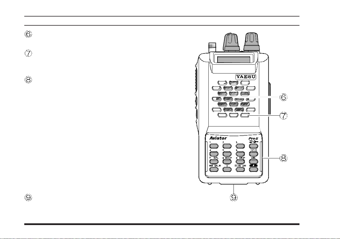
CONTROLS & CONNECTORS (FRONT PANEL
Loudspeaker
The internal speaker located in this position.
Microphone
Speak across this opening in a normal tone voice
while pressing the PTT switch.
Keypad
Several keys have dual functions. The color of
the label determines the way in which you activate the function:
The white labels represent the primary functions
of the keys (activated by simply pressing the key
momentarily).
The yellow labels represent the secondary functions of the keys (activated by pressing the [F
key first, then the indicated key).
On the keypad, primary functions (white) are labeled to the left, while the secondary functions
(yellow) are labeled to the right. These functions
are described in detail on the next page.
)
]
Battery Pack Latch
Open this latch for battery removal.
4
VXA-120 AVIATOR PROII OPERATING MANUAL
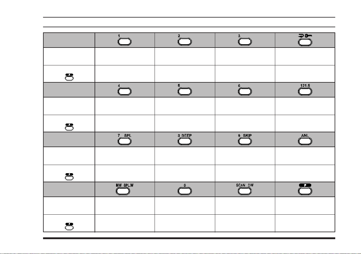
CONTROLS & CONNECTORS (KEYPAD
)
Primary Function
(
Press Key
Secondary Function
(
Press +
Primary Function
(
Press Key
Secondary Function
(
Press +
Primary Function
(
Press Key
Secondary Function
(
Press +
Primary Function
(
Press Key
Secondary Function
(
Press +
)
)
)
)
)
)
)
)
Frequency Entry
Digit 1
Frequency Entry
Digit 4
None
Frequency Entry
Digit 7
Activates Split (Duplex
mode
Memory “Write”
Command
Split-Memory “Write”
Command
Frequency Entry
Digit 2
Frequency Entry
Digit 5
None None None
Frequency Entry
Digit 8
)
On/Off Switch
for Keypad Beeper
Frequency Entry
Digit 0
Frequency Entry
Digit 3
NoneNoneNone
Frequency Entry
Digit 6
Frequency Entry
Digit 9
Allows Skipping of
Channel during Scan
Activates Scanning
Activates Dual Watch
Selects Memory Display
Type (page 19)
Locks the Keypad
Selects Emergency
Channel (121.5 MHz
Activates Automatic
Noise Limiter
None
Activates “Secondary”
Key mode
NoneNone
)
VXA-120 AVIATOR PROII OPERATING MANUAL
5
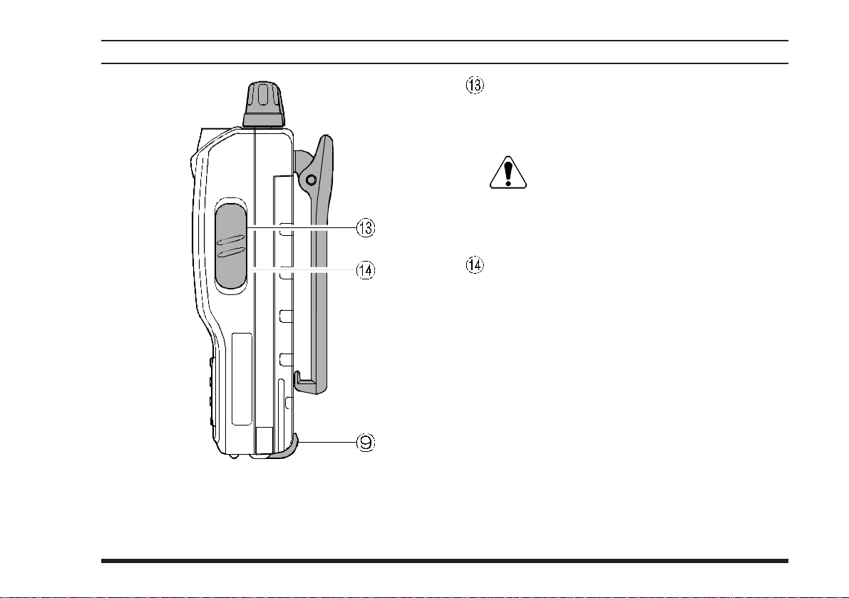
CONTROLS & CONNECTORS (LEFT SIDE
)
PTT (PUSH TO TALK
Press this button to transmit when you are operating in the “
return to the “R
COMCOM
COM” band. Release this button to
COMCOM
ECEIVE” mode. See page 15.
)
Switch
MONITOR Switch
This button may be pressed to “open” the squelch
manually, allowing you to listen for very weak
signals. Press and hold this button for 2 seconds,
to “open” the squelch continuously. Press this
button again to resume normal (quiet) monitoring. See page 12.
LAMP Switch
Press this switch momentarily, to activate the
back-lighting lamp for the display. Press and hold
this switch for 2 seconds, to activate the backlighting lamp continuously. To turn the lamp of f,
press this switch again. The LAMP switch may
be configured in several ways via the Menu; see
page 28 for details.
6
VXA-120 AVIATOR PROII OPERATING MANUAL
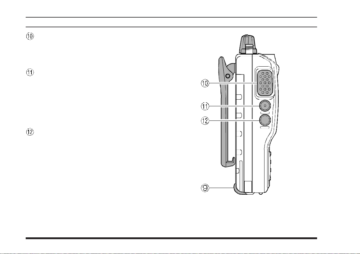
CONTROLS & CONNECTORS (RIGHT SIDE
MIC/EAR Jack
You may connect the (optional) CT-60 Headset
Cable or the (optional) MH-44
crophone to this jack.
Never connect the any Speaker/Micro-
phone that is not recommended by the
manufacturer . Because these jack connections are
unique using a Speaker/Microphone that is not
specified by Y aesu will damage the
EXT DC Jack
When an external 12-Volt DC power source is
available, you may connect the E-DC-5B External DC Cable here. Do not connect any wire to
this jack if that wire is connected directly to a
28-V olt DC source. Connecting the VXA-120 di-
rectly to a source which exceeds 15.0 Volts DC
will result in damage to the unit.
)
A4B Speaker/Mi-
VXA-120
.
VXA-120 AVIATOR PROII OPERATING MANUAL
7

BEFORE YOU BEGIN
Precautions
r This apparatus is capable of two-way communi-
cation on channels used for critical aviation safety
communications. Therefore, it is important that
this radio be kept away from children or other
unauthorized users at all times.
r When making DC connections via the E-DC-5B
DC cable, be absolutely certain to observe the
proper voltage level and polarity guidelines. Do
not connect this radio directly to any 24 ~ 28
Volt DC source, nor to AC power of any kind.
Connecting the VXA-120 directly to a source
which exceeds 15.0 Volts DC will result in damage to the unit.
r Do not dispose of the Ni-Cd Battery Pack in a
fire. Do not carry a Ni-Cd Battery Pack in your
pocket, where keys or coins could short the terminals. This could create a serious fire/burn danger, and possibly cause damage to the Ni-Cd
pack.
r Although the VXA-120 is designed to be water
resistant, the enclosure is not “waterproof.” Do
not allow the radio to become submersed in water, and do not expose it and/or its Ni-Cd Battery
Pack to water spray under pressure.
Battery Installation and Removal
¦ To install the battery, hold the transceiver with
your left hand, so your palm is over the speaker
and your thumb is on the top of the Belt Clip.
Insert the battery pack into the battery compartment on the back of the radio while tilting the
Belt Clip outward, then close the Battery Pack
Latch until it locks in place with a “Click.”
¦ To remove the battery, turn the radio off and re-
move any protective cases. Open the Battery Pack
Latch on the bottom of the radio, then slide the
battery downward and out from the radio while
unfolding the Belt Clip.
Do not attempt to open any of the recharge-
able Ni-Cd packs, as personal injury or damage to the Ni-Cd pack could occur if a cell or cells
become accidentally short-circuited.
8
VXA-120 AVIATOR PROII OPERATING MANUAL
BEFORE YOU BEGIN
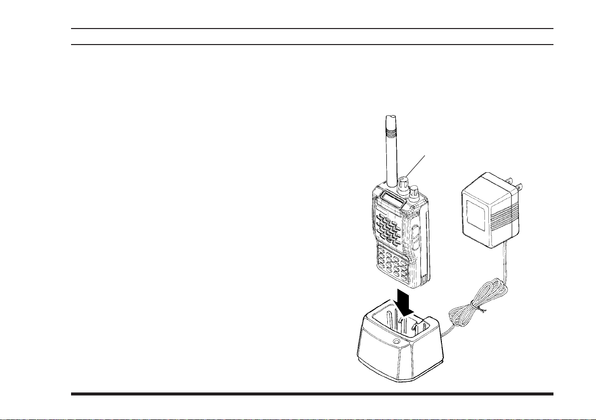
Battery Charging
It is necessary to fully charge the Ni-Cd battery before it’s first use. Follow these procedures:
¦ Install the supplied FNB-V57 Ni-Cd battery pack
onto the transceiver. Ensure that the transceiver
is switched off.
¦ Plug the NC-76 into the AC line outlet.
¦ Insert the battery pack into the NC-76; the an-
tenna jack should be at the left side when viewing the charger from the front.
¦ If the battery pack is inserted correctly, the RED
indicator will glow . A fully-discharged pack will
be charged completely in 15 hours.
Important Notes:
r The NC-76 is not designed to power the trans-
ceiver for operation (reception or transmission).
r Do not leave the charger connected to the trans-
ceiver for continuous periods in excess of 24
hours. Long term overcharging can degrade the
Ni-Cd battery pack and significantly shorten its
useful life.
r If using a charger other than the NC-76 , or if
using a battery pack other than the FNB-V57,
follow the appropriate instructions provided with
the charger/battery. Contact your Dealer if you
have any doubts about the appropriateness of the
particular charger or battery pack you intend to
use.
Must be transceiver
switched off.
To AC line outlet
VXA-120/NC-76
VXA-120 AVIATOR PROII OPERATING MANUAL
9

BEFORE YOU BEGIN
Low Battery Indication
¦ As your battery discharges during use, the volt-
age will gradually become lower. When the battery voltage reaches 5.0 Volts, the “ x ” icon
will blink on the LCD display, indicating that
the battery pack must be recharged before further use.
¦ Avoid recharging Ni-Cd batteries before the
“Low Battery” indicator is observed, as this can
degrade the charge capacity of your Ni-Cd battery pack. Yaesu recommends that you carry an
extra, fully-charged pack with you so you will
not lose communications capability due to a depleted Ni-Cd battery.
This “deep cycling” practice will help to maintain longer overall battery life after many recharging cycles.
Installing the FBA-25 (option) Alkaline
Battery Case
The optional FBA-25 Battery Case allows operation of the VXA-120 using six “AA” size Alkaline
batteries.
When installing batteries, insert the (–) end first, then
press in the (
Always replace all six batteries at the same time, paying attention to the polarity indicated inside the case.
tain the thermal and over-current protection circuits (provided in the “FNB” series of Ni-Cd Battery Packs) required when utilizing Ni-Cd cells.
++
+) end so the battery snaps into place.
++
The FBA-25 must not be used with re-
chargeable cells. The FBA-25 does not con-
10
VXA-120 AVIATOR PROII OPERATING MANUAL
 Loading...