

Page 1
VX-6000
POWER
OPERATING MANUAL
MANUAL DE OPERACIÓN
VERTEX STANDARD CO., LTD.
4-8-8 Nakameguro, Meguro-Ku, Tokyo 153-8644, Japan
VERTEX STANDARD
US Headquarters
17210 Edwards Rd., Cerritos, CA 90703, U.S.A.
International Division
8350 N.W. 52nd Terrace, Suite 201, Miami, FL 33166, U.S.A.
YAESU EUROPE B.V.
P.O. Box 75525, 1118 ZN Schiphol, The Netherlands
YAESU UK LTD.
Unit 12, Sun Valley Business Park, Winnall Close
Winchester, Hampshire, SO23 0LB, U.K.
YAESU GERMANY GmbH
Am Kronberger Hang 2, D-65824 Schwalbach, Germany
VERTEX STANDARD HK LTD.
Unit 5, 20/F., Seaview Centre, 139-141 Hoi Bun Road,
Kwun Tong, Kowloon, Hong Kong
Page 2

Congratulations!
You now have at your fingertips a valuable communications tool - a Vertex Standard
two-way radio! Rugged, reliable and easy to use, your Vertex Standard radio will
keep you in constant touch with your colleagues for years to come, with negligible maintenance down time.
Please take a few minutes to read this manual carefully. The information presented here
will allow you to derive maximum performance from your radio. After reading it, keep
the manual handy for quick reference, in case questions arise later on.
We’re glad you joined the Vertex Standard team. Call on us any time, because our
business is communications. Let us help you get your message across.
NOTICE
There are no user-serviceable points inside this transceiver. All service jobs must
be referred to your Authorized Service Center or Network Administrator.
Safety / Warning Information
WARNING - DO NOT operate the VX-6000U radio when someone (bystanders)
outside the vehicle is within 47 inches (1.2 meter) of the antenna.
Safety Training information:
Antennas used for this transmitter must not exceed an antenna gain of 0 dB. The
radio must be used in vehicle-mount configurations with a maximum operating
duty factor not exceeding 50%, in typical Push-to-Talk configurations.
This radio is restricted to occupational use, work related operations only where the
radio operator must have the knowledge to control the exposure conditions of its
passengers and bystanders by maintaining the minimum separation distance of 47
inches (1.2 m).
Failure to observe these restrictions will result in exceeding the FCC RF exposure
limits.
Antenna Installation:
For rear deck trunk installation, the antenna must be located at least 47 inches (1.2
m) away from rear seat passengers in order to comply with the FCC RF exposure
requirements.
For roof top installation, the antenna must be placed in the center of the roof.
Page 3
VX-6000 Operating Manual
VX-6000 Operating Manual
POWER
The VX-6000 Series are full-featured FM transceivers designed for flexible mobile and
base station business communications in the VHF Low-Band (110/25 Watts: programmable), VHF High-Band (100/25 Watts: programmable) and UHF (100/25 Watts: programmable) Land Mobile Bands. Each model is designed for reliable business communications in a wide variety of applications, with a wide range of operating capability provided by its leading-edge design.
The 250-channels memories can each be programmed with a 8-character channel name. A
39-tone programmable CTCSS encoder/decoder is built in as standard.
Important channel frequency data is stored in EEPROM and flash memory on the CPU,
and is easily programmable by dealers using a personal computer and the VERTEX STANDARD CT-71 Programming Cable and CE35 Software.
Special built-in features include:
! The 250-channels memories can each be programmed with a 8-character channel
name.
! CTCSS (Continuous Tone Coded Squelch System);
! DCS (Digitally Coded Squelch);
! Extensive Selective Calling selections; and
! Two sets of scanning channels, one set preset by the dealer and another which is
operator-selectable.
The pages which follow will detail the many advanced features provided on the VX-6000
transceiver. After reading this manual, you may wish to consult with your Network Administrator regarding precise details of the configuration of this equipment for use in your
application.
Page 1
Page 4
VX-6000 Operating Manual
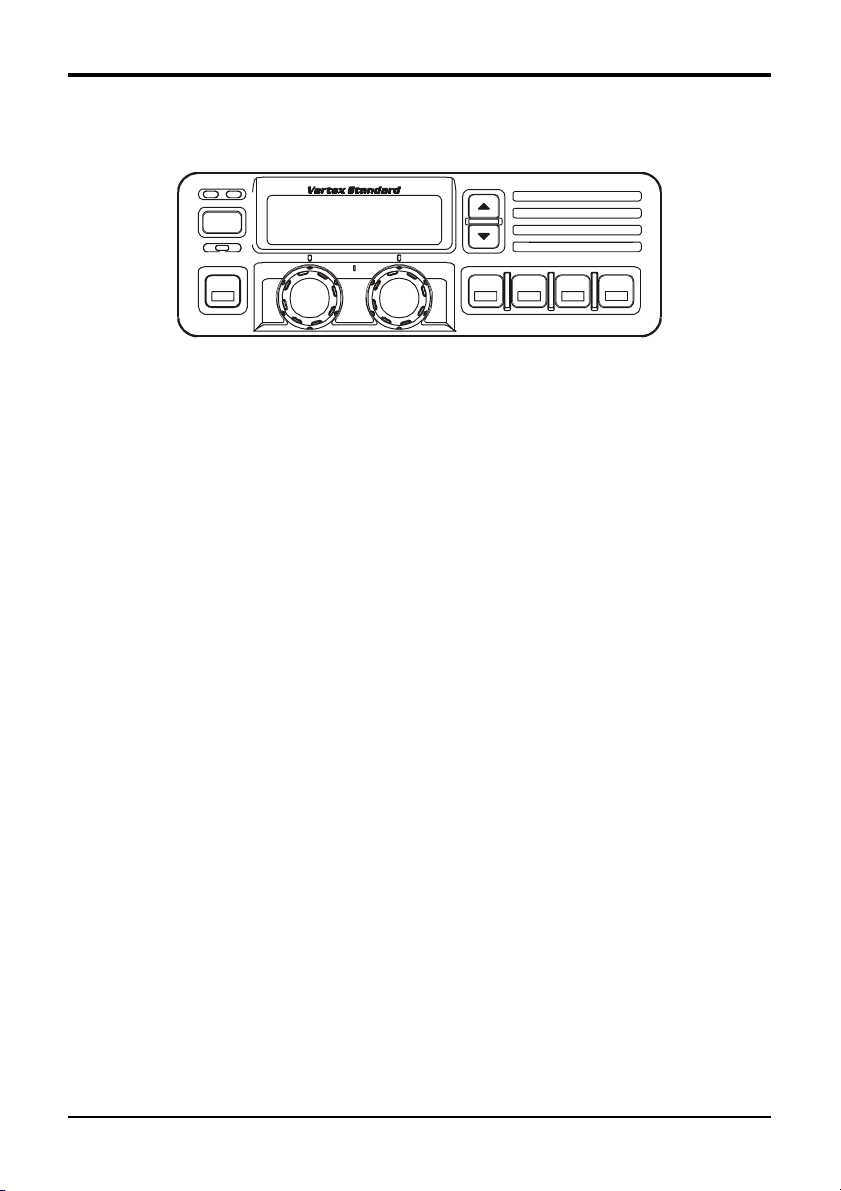
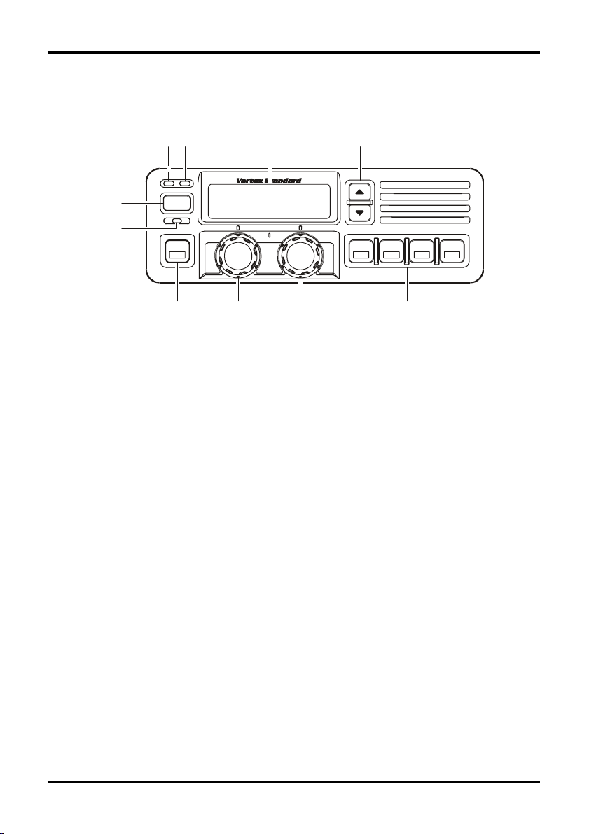
Controls & Connectors
Front Panel
$#%&
"
POWER
'
A
(
PWR Button
"
Press the button to turn the transceiver ON and OFF.
TX Indicator
#
This lamp glows red when the radio is transmitting.
BUSY Indicator
$
This lamp glows green when the channel is busy.
Liquid Crystal Display
%
The display include an 8-character alpha-numeric section showing channel and group
names, status and identity information, and error messages. Additional indicators on
the display show priority channel assignments and scan include / exclude selection.
!!
""
!/
" Button
!!
&
""
Pressing these buttons changes the current group (and displayed group number or
name). Holding this button for more than 1/2 second causes the function to repeat.
)* +
HOME Indicator
'
This lamp glows orange when incorrect position at the setting of CE35.
Programmable Function Button
(
This button can be set up for special applications, such as high/low power selection,
monitor, dimmer, talk-around, and call alert function, as determined by your network
requirements and programmed by your VERTEX STANDARD dealer.
The default function is set as Dimmer Button.
Page 2
Page 5
VX-6000 Operating Manual
VOLUME Knob
j
This knob sets the volume of the receiver.
CHANNEL Selector Knob
k
This knob select the operating channel.
Programmable Function Button
l
This button can be set up for special applications, such as high/low power selection,
monitor, dimmer, talk-around, and call alert function, as determined by your network
requirements and programmed by your VERTEX STANDARD dealer.
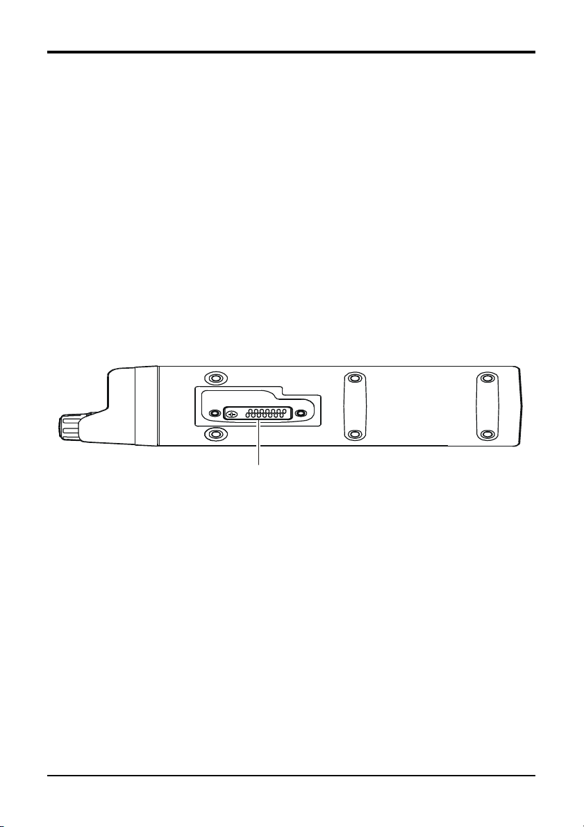
Side Panel
Microphone Jack (It is on both sides.)
Connect the microphone plug to this jack.
Microphone Jack
Page 3
Page 6

VX-6000 Operating Manual
REAR (Heatsink)
%
$#"
13.8-V DC Cable Pigtail w/Connector
!!
!
!!
The supplied DC power cable must be connected to this 2-pin connector. Use only
the supplied fused cable, extended if necessary, for power connection.
External Speaker Jack
""
"
""
An external loudspeaker may be connected to this 2-contact, 3.5-mm mini-phone
jack.
Caution: Do not connect this line to ground, and be certain that the speaker has
adequate capability to handle the audio output from the VX-6000.
Antenna Cable with Connector
##
#
##
The 50-ohm coaxial feedline to the antenna must be connected here using a type-M
(PL-259) plug.
DSUB 25-Pin Accessory Connector
$$
$
$$
External TX audio line input, PTT (Push To Talk), Squelch, and external RX audio
line output signal may be obtained from this connector for use with accessories such
as data transmission/reception modems, ets.
Page 4
Page 7

VX-6000 Operating Manual
Basic Operation of the Transceiver
Important! - Before turning on the radio the first time, confirm that the power connec-
tions have been made correctly and that a proper antenna is connected to the antenna jack.
Switching Power ON/OFF
Push the POWER switch turn on the radio. The display will become illuminated.
The radio will start up on the last channel used prior to shut-down during the previous operating session.
The display should show either a channel number or scan mode indicator (DSC,
USC, GDS, GUS, PDS, PUS, DDW or UDW). If “ERR” is displayed instead, the
transceiver has not yet been programmed with channel frequencies; switch off the
power and contact your network administrator or VERTEX STANDARD dealer. If
a scan mode indicator is displayed, you can press the SCAN button to display a
channel number, and then press either the UP (!) or DOWN (") button to change
channels.
Setting the Volume
Turn the VOL knob clockwise to increase the volume, and counterclockwise to decrease it.
Transmitting
To transmit, wait until the “BUSY” indicator is off (the channel is not in use), and
press the PTT (Push-To-Talk) switch on the side of the microphone (the “TX” indicator will appear or the “TX” indicator will glow red). While holding in the PTT
switch, speak across the face of the microphone in a clear, normal voice level, and
then release the PTT switch to receive.
Automatic Time-Out Timer
If the selected channel has been programmed for automatic time-out, you must limit
the length of each transmission. While transmitting, a beep will sound five seconds
before time-out. Another beep will sound just before the deadline; the “TX” indicator will disappear and transmission will cease soon thereafter. To resume transmitting, you must release the PTT and wait for the “penalty timer” to expire (if you press
the PTT before this timer expires, the timer restarts, and you will have to wait another “penalty” period).
Selecting Groups and Channels
% Press the UP (!) or DOWN (") button (repeatedly, if necessary) to select a dif-
ferent group of channels.
% Turn the CHANNEL selector knob to select a different channel within the current
group.
Page 5
Page 8

VX-6000 Operating Manual
Advanced Operation
Programmable Function Button
The VX-6000 includes the seven Programmable Function Buttons. The Program-
mable Function Button functions can be customized, via programming by your VER-
TEX STANDARD dealer, to meet your communications/network requirements. Some
features may require the purchase and installation of opetional internal accessories. The
possible Programmable Function Button programming features are illustrated at the
below, and their functions are explained on page ?.
For further details, contact your VERTEX STANDARD dealer. For future reference, check
the box next to each function that has been assigned to the Programmable Function
Button on your particular radio, and keep it handy.
POWER
Functions Programmable Function Button
None
Call/Reset
Talk-Around
Noise Blanker
Alpha Numeric
DIM
EMG
HA
Home
IC
MONI
NB
GRP UP/DWN
CH UP/DWN
PA
SCAN
SP*
SQL
Encryption**
* requires YSK-4000
** requires Encryption Unit
Page 6
Page 9

VX-6000 Operating Manual
Scanning Modes
There are eight scanning modes, described in the list below. Each channel can be
independently enabled or disabled for scanning; only channels selected for scanning
within the enabled group are scanned. Also, as mentioned before, each group can
have up to two priority channels which are scanned more often than the non-priority
channels.
The SCAN modes and their corresponding displays are as follows:
Display Scanning Function
DSC Dealer Scan (only within the current group)
USC User Scan: only user-selected channels (only within the current group)
GDS Group Dealer Scan: scan all Dealer-selected channels in all groups
GUS Group User Scan: scan all User-selected channels in all groups
PDS Priority Dealer Scan: DSC plus priority channel(s)
PUS Priority User Scan: USC plus user priority channel(s)
DDW Dealer Dual Watch: Monitor one channel and priority channel(s)
UDW User Dual Watch: Monitor User-selected channel and priority channel(s)
Scanning Operation
With the microphone in its hanger, press the assigned Programmable Function
Button of the “SCAN” momentarily to activate scanning. Typically, “DSC” will
initially appear on the display, indicating Dealer Channel Scan as the scanning mode.
If you wish to change to one of the modes described in the list above, press the
assigned Programmable Function Button of the “SEL” button repeatedly until
that mode appears on the display.
If you pick up the microphone while no signal is being received, operation will shift
to a particular channel. Which channel that will be depends on which of the following options the dealer has programmed for off-hook channel selection:
Scan Start Channel
Lifting the microphone causes operation to revert to the group and channel last selected before scanning started or resumed.
Priority Revert
Lifting the microphone activates the Priority 1 channel in the current group. If no
channel is assigned level 1 priority, operation will be on the Priority 2 channel. If no
priority channels have been assigned, operation reverts to the Scan Start Channel.
Last Busy
Lifting the microphone causes operation to revert to the group and channel where
activity was last detected. If no activity was detected since turning on the radio,
operation reverts to the Scan Start Channel.
Page 7
Page 10

VX-6000 Operating Manual
How to Select Channels to be Scanned
If your radio has been configured by your Dealer to allow you, the operator, to make
changes to the list of channels to be scanned, you can make these changes by following
this simple process:
Press and hold in the SEL button; while holding this button in, press the POWER
!
button to turn the radio on. You may now release the ?? button.
Press the ?? button, as necessary, until the Memory Group and Memory Channel
"
numbers will appear in small characters in the right side of the display area.
You may now push the ?? key momentarily as many times as necessary to choose
#
the Memory Group within which you wish to make changes to the channel scan
list. Once you have selected the desired Memory Group, you may use the UP (!)
or DOWN (") button to choose a particular channel within the current group.
Pressing the ?? button will change the scanning status of the selected channel.
If you are adding the channel to those you wish to scan, pressing the ?? button
causes a “U” appear on the display, indicating that the channel has been added to
the User Scan List. If you are deleting the channel from the User Scan List (the
channel's data itself will not be deleted; the channel just will not be scanned), the
“U” will disappear.
Repeat step 3 for each channel you wish to enable or disable for scanning.
$
When you are done making changes to the channels you wish to scan, press and
&
hold in the ?? button for more than 1.5 second. Operation will return to its normal
status, and the display will revert to its previous appearance.
Page 8
Page 11

VX-6000 Operating Manual
How to Change the “User Priority” Channels
Your Dealer may have configured your radio so as to allow you to make changes to the
“User Priority” Channels (the channels you designate to be scanned more frequently than
the others). The selection process is almost identical to that used for making changes to
the User Scan List.
Turn the transceiver OFF by press the POWER button.
!
Press and hold in the ?? button; while holding this button in, press the POWER
"
button to turn the radio on. You may now release the ?? button.
Press the ?? button, as necessary, until the Memory Group and Memory Channel
#
numbers will appear in large characters in the right side of the display area (as
compared to small characters in the case of changes to the Scan List).
You may now push the ?? button momentarily as many times as necessary to choose
$
the Memory Group within which you wish to make changes to the User Priority
Channel(s). Once you have selected the desired Memory Group, you may use the
UP (!) or DOWN (") button to choose a particular channel within the current
group.
Pressing the ?? button will change/assign the Priority status of the selected channel.
If you are assigning the channel to Priority status, pressing the ?? button causes
“Pr1” or “Pr2” to flash on the display, indicating that the channel has been assigned the status of Priority 1 or Priority 2, respectively. Pressing the ?? button
repeatedly toggles the Priority Level between “1” and “2.” If you are deleting the
channel from Priority status, the “Prn” indicator will disappear.
Repeat step 4 for each channel you wish to assign to or delete from Priority status.
&
When you are done making changes to the Priority Channels, press and hold in the
'
?? button for more than 1.5 second. Operation will return to its normal status, and
the display will revert to its previous appearance.
Page 9
Page 12

VX-6000 Operating Manual
ARTS (Auto Range Transpond System)
This system is designed to inform you when you and another ARTS-equipped station are
within communication range.
During ARTS operation, your radio automatically transmits for about 1 second every 25
(or 55) seconds (the interval is programmed by Dealer) in an attempt to “Shake hands”
with the other station.
If you move out of range for more than one minutes, your radio senses that no signal has
been received, a ringing beeper will sound. If you subsequently move back into range, as
soon as the other station transmits, your beeper will sound.
The A Button Function
The A (Accessory) button can be programmed by the dealer to provide two of the other
functions described below.
To activate the primary Accessory function, press the A button momentarily. To access
the secondary Accessory function (which may include the Alarm), press and hold the A
button for 1.5 seconds or longer.
Call/Reset
When this feature is programmed and a selective call has been received ,momentarily press the A button to reset the flashing indicator and mute the receiver, otherwise press the A button to sent your radio’s identification code (ANI) to the dispatcher.
Talk-Around
The feature causes the A button to select simplex operation on semi-duplex channels: the transmit frequency becomes the same as the receive frequency (regardless
of any programmed offset for the channel).
Note: This feature has no effect on simplex channels. After pressing the button,
“TA” is displayed on the LCD.
Noise Blanker
Because local noise can be particularly troublesome in the VHF Low-Band frequency
spectrum, the Low-Band version of the VX-6000 includes a Noise Blanker feature,
which may be toggled on and off by pressing the A button for the appropriate length
of time.
Alpha Numeric
Press this key to switch the display between the Group/Channel number, and the
Group/Channel name (alphanumeric). A tone will sound each time you switch between numerical and alphanumerical display.
DIM
Press this key to adjust the brightness of the display and key backright.
Page 10
Page 13

VX-6000 Operating Manual
EMG (Emergency)
Press this key to initiate an emergency call (requires ANI board). When an emergency call is made, not tone is emitted and the display does not change. To end the
emergency call, turn the transceiver power OFF.
HA (Horn Alert)
Press this key to turn the Horn Alert function ON or OFF. If you receive a call from
the base station with 2Tone or DTMF signaling, horn alert will activate.
When you turn Horn Alert ON, a tone will sound and “HA” appears on the display.
Home (Home Channel)
Press this key to select the pre-programmed Home Channel. Press it again to return
to the previous channel. If used while scanning, pressing this key a second time will
change to the revert channel.
IC (Intercom)
This feature requires dual head configuration. Press this key to turn the intercom
feature ON or OFF. While ON, you can press the PTT switch to communicate to
another control head operator without transmitting over the air. When you press this
key, a tone sounds and “INTERCOM” appears on the display. The intercom can be
used even while scanning and receiving a call.
MONI (Monitor)
Press this key momentarily to cancel CTCSS and DCS signaling squelch; the “MON”
icon appears on the display. Press and hold this key for 1/2 seconds to hear background noise (unmute the audio); the MON icon blinks on the display.
GRP UP/DWN
Press this key to select a different group of channels.
CH UP/DWN
Press this key to select a different channel within the current group.
PA (Public Address)
Press this key to use the transceiver as a PA amplifier. When you enable this function, a tone sounds and PA appears on the display. The public address can be used
even while scanning and receiving a call.
SCAN
Press this key to start or stop the scanning sequence.
SP
Press this key to switch “Front panel”, “Front panel & Body” and “Body” speaker.
When “Body” is selected, a tone sounds and the “SP” icon appears on the display.
You can use this function while scanning and receiving a call. However, all audio
will be emitted from the PA speaker.
Page 11
Page 14

VX-6000 Operating Manual
SQL (Squelch Level)
You can manually adjust the squelch level using this function:
1. Press the this key. A tone sounds and SQL appears on the display with the current
squelch level.
2. Rotate the DIAL knob to select the desired level.
3. Press the this key. A tone sounds and the display returns to the normal channel.
Encryption (Option)
When the Voice Scrambler feature is enabled, pressing the A button toggles the Scrambler on and off.
Optional Accessories
B7A
MH-25
MH-53
MH-53
CE35 Programming Software (for IBM PC/compatibles only)
CT-71 PC Programming Cable (CT-29 + CT-70)
CT-72 Cloning Cable
MLS-100 External Loudspeaker
MMB-**
F2D-9 2-Tone / DTMF
VTP-60 VX-Trunk Unit
YSK-4000 Separation Kit
Hand Microphone
A7A
Hand Microphone (Noise Canceling)
B7A
DTMF Keypad Microphone (Noise Canceling)
Page 12
Page 15

This device complies with Part 15 of the FCC rules.
Operation is subject to the condition that this device
does not cause harmful interference.
Page 16

Copyright 2001
VERTEX STANDARD CO., LTD.
All rights reserved
No portion of this manual
may be reproduced without
the permission of
VERTEX STANDARD CO., LTD.
Printed in Japan.
0105?-0?
 Loading...