

Page 1
O
PERATING MANUAL
Congratulations!
You now have at your fingertips a valuable
communications tool – a Yaesu two-way radio! Rugged,
reliable and easy to use, your Yaesu radio will keep you
in touch for years to come, with negligible maintenance.
Please take a few minutes to r ead this manual caref ully.
The information presented here will allow you to derive
maximum performance from your radio.
After reading it, keep the manual handy for quick
reference, in case questions arise later on.
We're glad you joined the Yaesu team. Call on us any
time, because our business is communications. Let us
help you get your message across.
NOTICE
There are no user-serviceable points inside this
transceiver. All service jobs must be referred to your
Authorized Service Center or Network Administrator.
Features
The VX-4000 Series are rugged basic-featured FM
transceivers designed for flexible mobile and base station
business communications in the 50-watts VHF and 40watts UHF
A highly integrated surface mount circ uit design and a
die-cast aluminum chassis assure reliability. Selectable
power output of LOW(5 – 25 watts) or High (VHF:50watts,
UHF:40watts) without the need of forced air cooling is
possible due to the large heatsink surface area of the
compartmentalized one-piece diecast chassis.
The 250-channels m emories c an each be progr amm ed
with a 8-character channel name.
A 39-tone programmable CTCSS encoder/decoder is
built in as standard.
A 104 standerd digital codes programmable DCS
encoder/decoder is built in as standard.
Important channel frequenc y data is stored in EEPROM
and flash memory on the CPU, and is easily
programmable by dealers using a personal computer and
the Yaesu
Software.
CT-71
Programming Cable and
CE-35
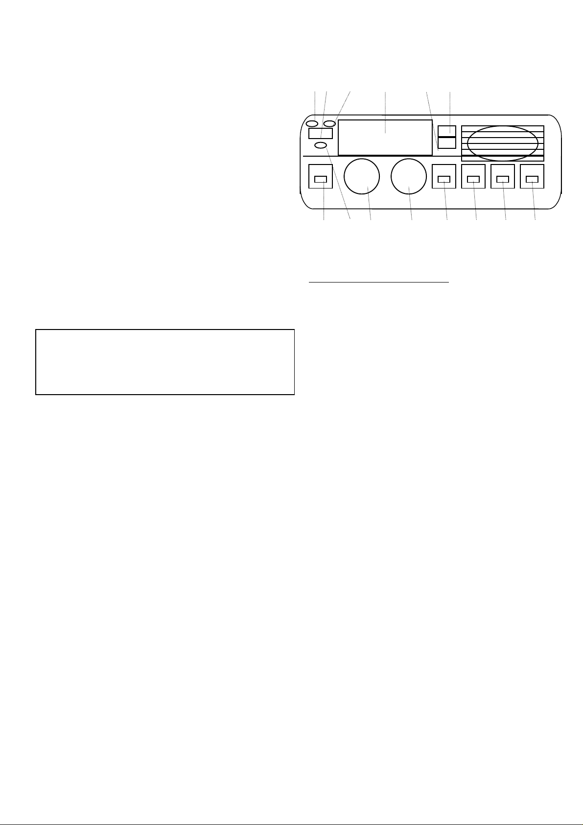
Front panel
1 2 3 4 5 6
7 8 9 10 11 12 13 14
ONTROL
C
1 TX Indicator
This lamp glows red when the radio is transmitting.
POWER
2
Turn the radio on or off.
(Press and hold in this button for 1.5 second.)
BUSY
3
This lamp glows green when the channel is busy.
Liquid Crystal Display
4
The display include an 8-character alpha-numeric
section showing channel and group names, status and
identity information, and error messages. Additional
indicators on the display show priority channel
assignments and scan include / exclude selection.
UP
5
Pressing this button changes the current group (and
displayed group number or name). Holding this button for
more than 1/2 second causes the function to repeat.
DOWN
6
Pressing this button changes the current group (and
displayed group number or name). Holding this button for
more than 1/2 second causes the function to repeat.
Programmable Function Button
7
This button can be set up for special applications , such
as high/low power selection, monitor, dimmer, talkaround, and call alert function, as determined by your
network requirements and programmed by your Yaesu
dealer.
The default function is set as
HOME
8
This lamp glows orange when incorrect position at the
setting of CE-35.
VOLUME
9
Button
Indicator
Indicator
& C
Knob
ONNECTORS
Dimmer
Button.
Page 2
This knob adjusts the receiver volume.
CHANNEL
10
This knob select the operating channel.
Programmable Function Button
11
The default function is set as
Programmable Function Button
12
The default function is set as
Programmable Function Button
13
The default function is set as no function Button.
Programmable Function Button
14
The default function is set as no function Button.
Rear
15 16 18
18
Antenna Socket
15
The 50-ohm coaxial feedline to the antenna must be
connected here using a type-M (PL-259) plug.
EXT SP (External Speaker)
16
An external loudspeaker may be connected to this 2contact, 3.5-mm mini-phone jack.
Caution: Do not connect this line to ground, and be
certain that the speaker has adequate capability to
handle the audio output from the radio.
13.8V DC Cable w/Connector
17
The supplied DC power cable must be connected to this
2-pin connector. Use only the supplied fused cable,
extended if necessary, for power connection.
DSUB 25-Pin Accessory Connector
18
External TX audio line input, PTT, Squelch, and external
RX audio line output signal may be obtained from this
connector for use with accessories such as data
transmission/reception modems, ets.
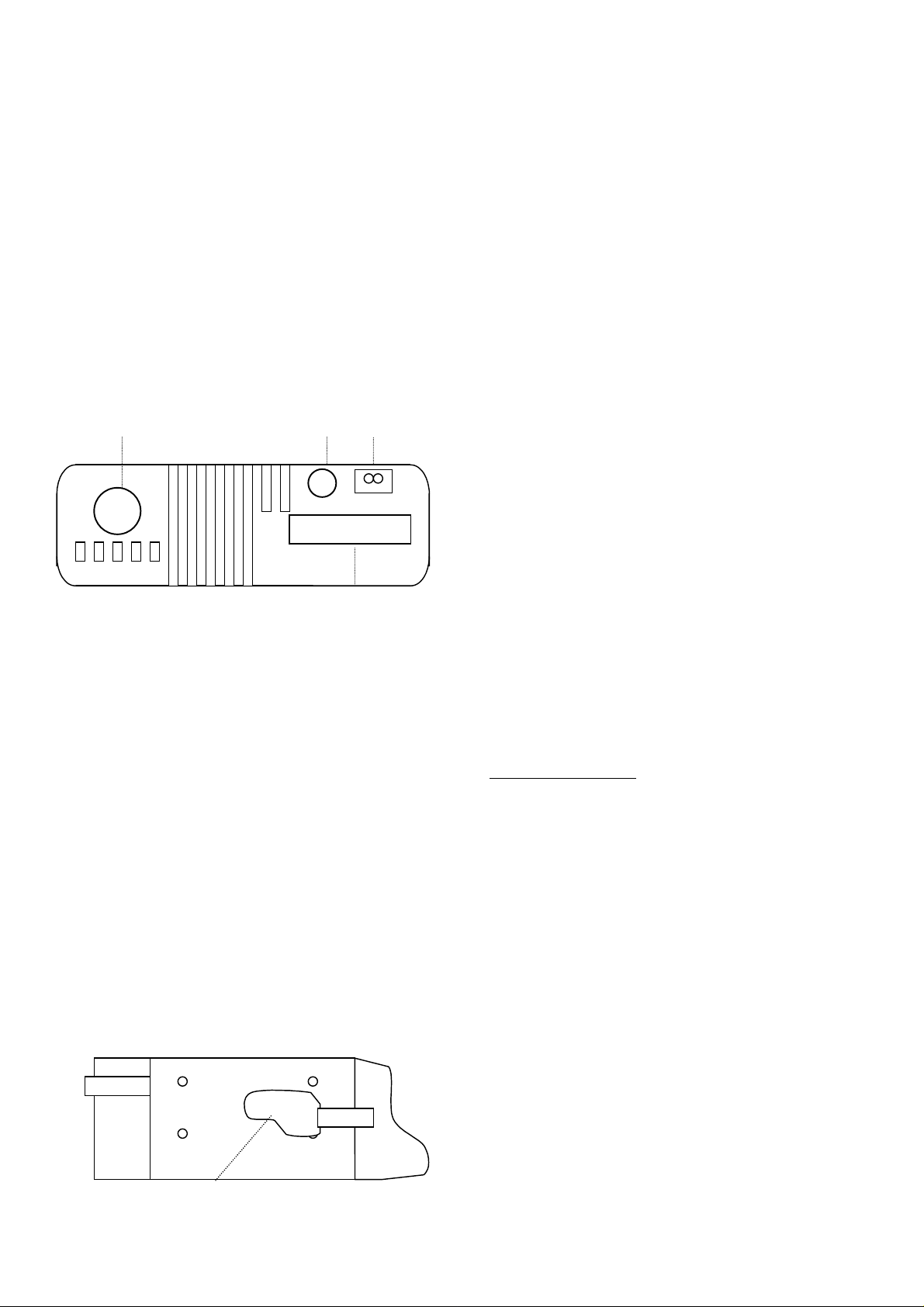
Side
19
Selector Knob
MONI
Button.
Low Power
Button.
Microphone Jack
19
Connect the microphone plug to this jack.
Basic Operation of the Transceiver
Important! –Before turning on the radio the first time,
confirm that the power connections have been made
correctly and that a proper antenna is connected to the
antenna jack.
Push the POW ER switch turn on the radio. The dis play
will become illuminated. The radio will start up on the last
channel used prior to shutdown during the previous
operating session.
Transmitting
To transmit, wait until the “BUSY” indicator is off (the
channel is not in use), and press the PTT (Push-To-Talk)
switch on the side of the microphone (the “TX ” lamp will
glow red). While holding in the PTT switch, speak across
the face of the mic rophone in a clear, nor m al voice level,
and then release the PTT switch to receive.
Automatic Time-Out Timer
If the selected channel has been programmed for
automatic time-out, you must limit the length of each
transmission. W hile transmitting, a beep will sound five
seconds before time-out. Another beep will sound just
before the deadline; the “T X” indic ator will disappear and
transmission will cease soon thereafter. To resume
transmitting, you must release the PT T and wait for the
“penalty timer” to expire (if you press the PT T before this
timer expires, the timer restarts, and you will have to wait
another “penalty” period).
Scanning Operation
With the microphone in its hanger, press the SCAN
button momentarily to activate scanning. Typically, “DSC”
will initially appear on the display, indicating Dealer
Channel Scan as the scanning mode. If you wish to
change to one of the m odes described in the list above,
press the SEL button repeatedly until that mode appears
on the display.
If you pick up the microphone while no signal is being
received, operation will shift to a particular channel.
Which channel that will be depends on which of the
following options the dealer has programmed for off-hook
channel selection:
Scan Start Channel
Lifting the microphone c auses oper ation to revert to the
group and channel last selected before s canning started
or resumed.
Priority Revert
Lifting the microphone activates the Priority 1 channel in
the current group. If no channel is assigned level 1
priority, operation will be on the Priority 2 channel. If no
Page 3

priority channels have been assigned, operation reverts
to the Scan Start Channel.
Last Busy
Lifting the microphone c auses operation to revert to the
group and channel where activity was last detected. If no
activity was detected since turning on the radio, operation
reverts to the Scan Start Channel.
Voting scan
The radio can be programmed for Voting Scan, whereby
the radio will lock onto the strongest signal in a preprogrammed set of channels. The radio is used as
normal, with the exception that transmission is not
allowed when the unit is out of range of the nearest
repeater. Consult your Yaesu dealer for more information
regarding this function.
Programmable Function Button
Low Power
With this featur e enable, a button toggles between high
and low transmitter power, as programmed by the dealer.
MONI
This function is monitoring for the current channel.
SCN
This function is start and stop the scanning.
HA
Horn Alert function On and Off.
Call/Reset
When this feature is program med and a selective call
has been received, momentarily press the button to reset
the flashing indicator and mute the receiver, otherwise
press the button to sent your radio’s identification code
(ANI) to the dispatcher.
Talk Around
The feature causes a button to select sim plex operation
on semi-duplex channels: the transmit frequency
becomes the sam e as the receive fr equency (regardless
of any programmed offset for the channel).
Note: This feature has no effect on simplex channels.
After pressing the button, ”TA” is displayed on LCD.
Encryption
W hen the Voice Scram bler f eature is enabled, press ing
a button toggles the Scrambler on and off.
Alarm Function
When the “alarm ” f unc tion is enabled, pres s ing a button
causes the radio to revert to a specially designated
channel, and causes the special “alarm” identifier code to
be transmitted automatically.
Note: This feature is only available as a “Secondary”
accessory to prevent accidental activation.
Fuse Replacement
If a fuse is blown, before replacing, see if you can
determine if it was caused by something outside of the
radio (perhaps a short circuit due to a worn cable or
pigtail near the radio). Contact your Ysesu dealer at once
if you do not find the cause. Replace fuses only with the
same type installed.
This is device complies with Part 15 of the FCC rules.
Operation is subject to the condition that this device does
not cause harmful interference.
Specifications
General
Frequency Range: 134-160MHz(VHF TYPE A)
Number of Channels & Spaci ng: MAX 250 channels
25kHz, 12.5kHz
Modes of Emission: 16K0F3E, 11K0F3E
Frequency Stability: 2.5ppm(-30 to
Antenna Requirements:50 ohms
Voltage Requirements: 13.8V ±15% DC
Current Consumption (approx.): RX: 1.4A
Operating Temperature Range: -30°C to 60°C (-22°F to 140°F)
148-174MHz(VHF TYPE C)
400-430MHz(UHF TYPE A)
450-480MHz(UHF TYPE D)
480-512MHz(UHF TYPE F)
+60°C)
Unbalanced (SO-239 socket)
Negative ground
TX: 12A(VHF 50W/UHF 60W)
Receiver
Receiver Circuit Type: Double-Conversion
Intermediate Frequencies : 43.95MHz, 450kHz
Sensitivity: 0.2µV 12dB SINAD (VHF)
Hum & Noise Ratio: Better than 45 dB (25kHz/step)
Adjacent Channel Selecti vity: >80dB (25-kHz/step VHF)
Intermodulation Distortion: Better than 78dB
Spurious Rejection: B etter than 85dB
Conducted Spurious Emi ssion: <-57dBm
Selectivity -6dB: >12kHz
-60dB: <30kHz
External Audio Output Power: 12 watts into 4 ohms
Superheterodine
0.25µV 12dB SINAD (UHF)s
Better than 40 dB (12.5kHz/step)
>78dB (25-kHz/step UHF)
>65dB (12.5-kHz/step)
with < 5% THD
Transmitter
Output Power: 50watts(UHF)
Modulation Type/Deviation: Frequency Modulation
Hum & Noise Ratio: Better than 45 dB (25kHz/step)
Modulation Distortion: Less than 5% at 1kHz
Spurious Emiss i on: Better than 65dB(below carrier)
Microphone Impedance: 600ohms
Microphone Sensitivity: -48dBm (3.0
40watts (UHF)
5watts (low programmable)
±5kHz(±2.5kHz)
Better than 40 dB (12.5kHz/step)
mV)
Physical
Size (WHD,approx.): 178mm x 60mm x 195 mm
Weight (approx.): 2.2kg
Specifications subject to change without notice or obligation.
Page 4

Optional Accessories
Accessories
MH-25B7A Hand Microphone
MH-43A7 Hand Microphone
(Noise Canceling)
MH-43B7 DTMF Keypad Mic
MLS-100 External Loudspeaker
FP-1025A AC Power Supply
CT-71 PC Programming Cable
(CT-29 + CT-70)
F2D-9 2-Tone / DTMF
LF-1 DC Line Filter
VTM-20 VX-Trunk II Trunking
Mobile Logic Board
CE-35 Programming Software
(IBM PC/compatibles only)
 Loading...