

Page 1

VX-2500 Operating Manual 1 of 15
2001. 10. 25 Ver 1.0
VX
VX –––– 2500
VX VX
Operating
Operating Manual
OperatingOperating
2500
2500 2500
Manual
Manual Manual
Page 2

VX-2500 Operating Manual 2 of 15
2001. 10. 25 Ver 1.0
Congratulations!
Congratulations!
Congratulations!Congratulations!
You now have at your fingertips a valuable communications tool-a VERTEX STANDARD two-
way radio! Rugged, reliable and easy to use, your VERTEX STANDARD radio will keep you in
constant touch with your colleagues for years to come, with negligible maintenance downtime.
Please take a few minutes to read this manual carefully. The information presented here will
allow you to derive maximum performance from your radio, in case questions arise later on.
We're glad you joined the VERTEX STANDARD team. Call on us anytime, because
communications is our business. Let us help you get your message across.
Notice !
Notice !
Notice !Notice !
There are no owner-serviceable parts inside the transceiver. All service jobs must be referred
to an autho-rized
VERTEX STANDARD Service Representative. Consult your Authorized VERTEX STANDARD
Dealer for installation of optional accessories.
Safety / Warning Information
Safety / Warning Information
Safety / Warning InformationSafety / Warning Information
WARNING - DO NOT operate the VX-2500 radio when someone (bystanders) outside the
vehicle is within following range.
Safety Training information:
Antennas used for this transmitter must not exceed an antenna gain of 0 dBd. The radio
must be used in vehicle-mount configurations with a maximum operating duty factor not
exceeding 50%, in typical Push-to-Talk configurations.
This radio is restricted to occupational use, work related operations only where the radio
operator must have the knowledge to control the exposure conditions of its passengers and
bystanders by maintaining the minimum separation distance of following range.
Failure to observe these restrictions will result in exceeding the FCC RF exposure limits.
Antenna Installation:
For rear deck trunk installation, the antenna must be located at least following range away
from rear seat passengers in order to comply with the FCC RF exposure requirements.
For roof top installation, the antenna must be placed in the center of the roof.
Radiated frequency and Distance
Radiated frequency and Distance
Radiated frequency and DistanceRadiated frequency and Distance
VX-2500U (D)
1.89 Feet
(0.576 m)
Page 3
VX-2500 Operating Manual 3 of 15
V
V
A
A
2001. 10. 25 Ver 1.0
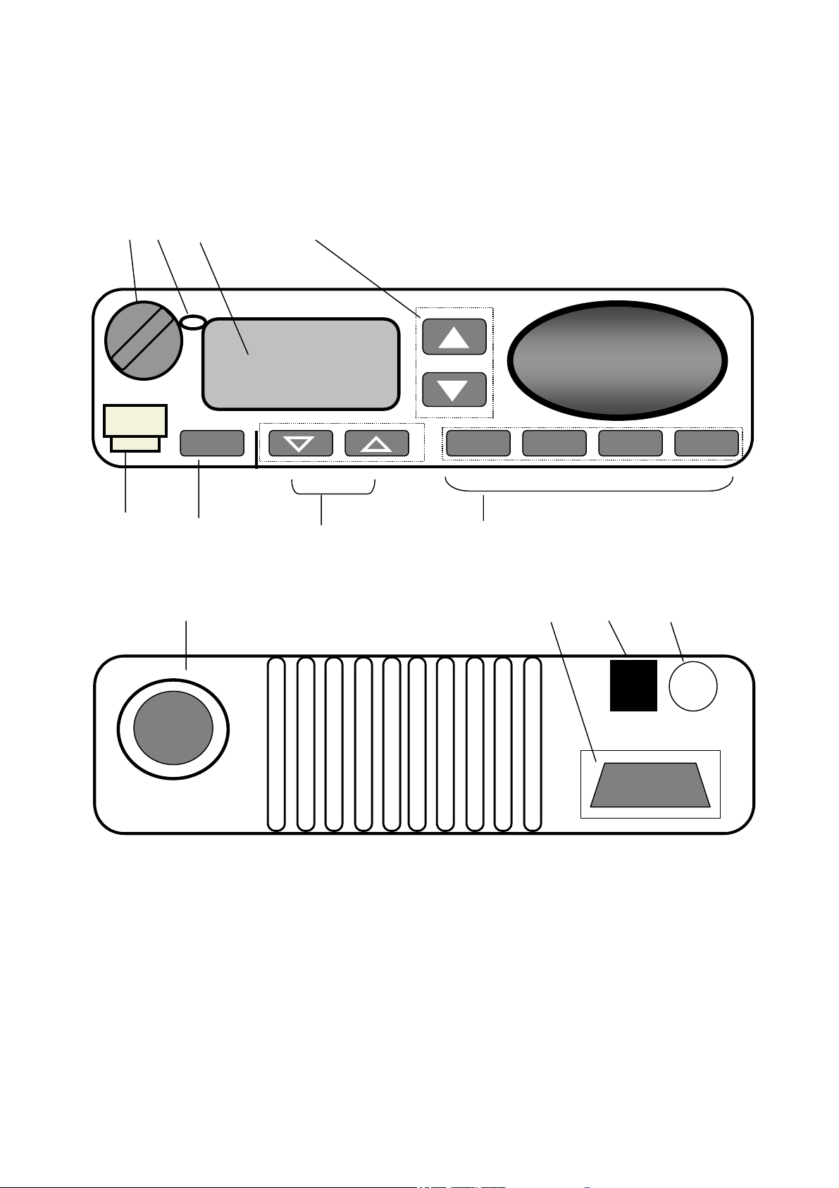
Control
FRONT
FRONT
FRONTFRONT
① ② ③
① ② ③ ④
① ② ③ ① ② ③
Vertex Standard
ertex Standard
ertex StandardVertex Standard
A
A
Controlssss & Connectors
ControlControl
④
④ ④
& Connectors
& Connectors & Connectors
P 1
P 1 P 2
P 1P 1
P 2 P 3
P 2P 2
P 3 P 4
P 3P 3
P 4
P 4P 4
⑤
⑤
⑤ ⑤
REAR
REAR
REARREAR
⑥
⑥
⑥ ⑥
⑨⑨⑨⑨⑩
⑦
⑦ ⑧⑧⑧⑧
⑦ ⑦
⑩⑪
⑩⑩
⑪⑫
⑪⑪
⑫
⑫⑫
Page 4

VX-2500 Operating Manual 4 of 15
2001. 10. 25 Ver 1.0
Important!
Important! – All buttons located on the Front Panel are Programmable Function Button (PF
Important!Important!
button)
button) determined by your network requirements and programmed by your VERTEX
button) button)
Programmable Function Button (PF
Programmable Function Button (PFProgrammable Function Button (PF
STANDARD dealer. Following instruction is along with nominal button programming.
VOL. / PWR Knob
①①①①
VOL. / PWR Knob
VOL. / PWR KnobVOL. / PWR Knob
Rotate the knob to turn the transceiver ON and OFF and set the volume of the
receiver.
②②②②
Busy / TX
Busy / Busy /
[Conventional]
[Conventional]
[Conventional][Conventional]
TX Indicator
Indicator
TXTX
Indicator Indicator
Busy /
This lamp glows red when the radio is transmitting and glows green when the
channel is busy.
Steady Green : Busy Channel
Blinking Green : Tone Squelch in defeated condition
Steady Red : Transmission in Progress
[LTR Trunking]
[LTR Trunking]
[LTR Trunking][LTR Trunking]
This lamp glows red when the radio is transmitting and glows green when the System
is busy (Indicating all channels of the System are busy.)
LCD (Liquid Crystal Display)
③③③③
LCD (Liquid Crystal Display)
LCD (Liquid Crystal Display)LCD (Liquid Crystal Display)
The display include an 8-character alpha-numeric section showing System and Group
names, status and identity information, and error messages. Additional indicators on
the display show priority channel assignments and scan include / exclude selection.
④④④④▲
▲・▼
・▼
▲▲
・▼ ・▼
Pressing these buttons changes the current Group (and displayed group number or
name). Holding this button for more than 1/2 second causes the function to repeat.
Microphone Jack
⑤⑤⑤⑤
Microphone Jack
Microphone JackMicrophone Jack
Connect the microphone plug to this jack.
A Button [Programmable Function Button ]
⑥⑥⑥⑥
A Button [Programmable Function Button ]
A Button [Programmable Function Button ]A Button [Programmable Function Button ]
This button can be set up for special applications, such as high/low power selection,
monitor, Talk-around, etc, as determined by your network requirements and
Steady Green : System Busy
Steady Red : Transmission in Progress
Button [Programmable Function Button ]
Button [Programmable Function Button ]
Button [Programmable Function Button ]Button [Programmable Function Button ]
programmed by your VERTEX STANDARD dealer.
⑦⑦⑦⑦▽
▽・△
・△
▽▽
・△ ・△
Pressing these buttons changes the current System (and displayed group number or
name). Holding this button for more than 1/2 second causes the function to repeat.
P1 to P4 [Progr
⑧⑧⑧⑧
P1 to P4 [Programmable Function Button ]
P1 to P4 [ProgrP1 to P4 [Progr
This button can be set up for special applications, such as High/Low power selection,
Button [Programmable Function Button ]
Button [Programmable Function Button ]
Button [Programmable Function Button ]Button [Programmable Function Button ]
ammable Function Button ]
ammable Function Button ]ammable Function Button ]
Page 5

VX-2500 Operating Manual 5 of 15
2001. 10. 25 Ver 1.0
Monitor, Talk-around, etc, as determined by your network requirements and
programmed by your VERTEX STANDARD dealer.
Antenna Socket
⑨⑨⑨⑨
Antenna Socket
Antenna SocketAntenna Socket
The 50-ohm coaxial feedline to the antenna must be connected here, using a type-M
(PL-259) plug.
D-Sub 9Pin Accessory Connector
⑩⑩⑩⑩
D-Sub 9Pin Accessory Connector
D-Sub 9Pin Accessory ConnectorD-Sub 9Pin Accessory Connector
External TX audio line input, PTT (Push To Talk), Squelch, and external RX audio
line output signal may be obtained from this connector for use with accessories such
as data transmission/reception modems, etc.
13.8V DC Cable Pigtail with Connector
⑪⑪⑪⑪
13.8V DC Cable Pigtail with Connector
13.8V DC Cable Pigtail with Connector13.8V DC Cable Pigtail with Connector
The supplied DC power cable must be connected to this 2-pin connector. Use only the
supplied fused cable, extended if necessary, for power connection.
External Speaker Jack
⑫⑫⑫⑫
External Speaker Jack
External Speaker JackExternal Speaker Jack
An external loudspeaker may be connected to this 2-contact, 3.5-mm mini-phone jack.
Caution: Do not connect this line to ground, and be certain that the speaker has
adequate capability to handle the audio output from the Radio.
Page 6

VX-2500 Operating Manual 6 of 15
2001. 10. 25 Ver 1.0
LCD Icons & Indicators
LCD Icons & Indicators
LCD Icons & IndicatorsLCD Icons & Indicators
BUSY
BUSY
TX
TX
TXTX
BUSYBUSY
TA
TA
TATA
Low
Low
LowLow
PRG
PRG
PRGPRG
TX
TX
TXTX
BUSY
BUSY
BUSYBUSY
TA
TA
TATA
Low
Low
LowLow
PRG
PRG
PRGPRG
Transmission in Progress as same as Red lamp.
Busy condition as same as Green lamp.
Talk-Around Mode
Low Transmit Power Mode On
Current Group on “ Scan” List
Status of current System /Group , such as Home , Priority .
8 Character Alpha-numeric Display of memorized System /Group Tagging
Page 7

VX-2500 Operating Manual 7 of 15
2001. 10. 25 Ver 1.0
Basic Operation of the Transceiver
Basic Operation of the Transceiver
Basic Operation of the TransceiverBasic Operation of the Transceiver
Important!
Important! - Before turning on the radio the first time, confirm that the power connections
Important!Important!
have been made correctly and that a proper antenna is connected to the antenna jack.
Overview -
Overview - Your Authorized VERTEX STANDARD Dealer can program your Radio for
Overview - Overview -
Trunking or Conventional format.
Switching Power ON/OFF
Switching Power ON/OFF
Switching Power ON/OFFSwitching Power ON/OFF
Rotate the VOL. / PWR Knob
▲▲▲▲・▼
・▼
・▼ ・▼
If you want to select the operating Group from a different System, press the
select the System you want before selecting the operating Group.
Setting the Volume
Setting the Volume
Setting the VolumeSetting the Volume
Turn the VOL. / PWR Knob
it.
If no signal is present, press and hold in the MON button more than 1/2 seconds; background
noise will now be heard, and you may use this to set the VOL. / PWR Knob
audio level. Press the MON button again to quiet the noise and resume normal (quiet)
monitoring.
If no signal is present, press the MON button, the bass sound will be heard. And you may use
this to set the VOL. / PWR Knob
VOL. / PWR Knob turn on the radio. The display will become illuminated. Press the
VOL. / PWR KnobVOL. / PWR Knob
Button
Button to choose the desired operating Group. A Group name will appear on the display.
ButtonButton
Button
▽▽▽▽・△
・△
・△ ・△
VOL. / PWR Knob clockwise to increase the volume, and counterclockwise to decrease
VOL. / PWR KnobVOL. / PWR Knob
[Conventional
[Conventional System
[Conventional[Conventional
[Trunking
[Trunking System
[Trunking[Trunking
VOL. / PWR Knob for the desired audio level.
VOL. / PWR KnobVOL. / PWR Knob
System]]]]
System System
System]]]]
System System
VOL. / PWR Knob for the desired
VOL. / PWR KnobVOL. / PWR Knob
Button to
ButtonButton
Transmitting
Transmitting
TransmittingTransmitting
[[[[Conventional System
Conventional System]]]]
Conventional SystemConventional System
1.
2.
3.
4.
In conventional mode, IT IS A FCC REQUIRMENT TO MONITOR A CHANNEL BEFORE
TRANSMITTING. Press the button programmed for monitoring. Listen for channel
activity.
When receiving a call, Transmit only after the incoming call ends. The radio cannot
receive a call and transmit simultaneously.
Press the PTT key. When a channel is available, the TXLED will glow red. The radio is
now transmitting and a voice message can be delivered. For best transmission, speak into
the microphone from a distance of 1- 1/2 to 2 inches. Release the PTT key after each
transmission.
If Busy Channel Lockout has been programmed for a channel, the radio will not transmit
Page 8

VX-2500 Operating Manual 8 of 15
2001. 10. 25 Ver 1.0
when a carrier is present. Instead, the radio will give a Continuos low-pitched tone while
the PTT key is pressed. Release the PTT key and wait for channel activity to stop.
5.
1.
2.
If CTCSS or Digital-Coded Squelch (DCS) Lockout has been programmed for a channel, the
radio can transmit only when there is no carrier being received or when the carrier being
received includes the correct CTCSS tone or DCS code.
[[[[Trunking System
Trunking System]]]]
Trunking SystemTrunking System
Press the PTT key. When a channel is available, the TX LED will glow red steadily. The
radio is now transmitting and a voice message can be delivered.
If all channels are busy, a continuous tone will be heard and BUSY
LCD when the PTT key is pressed. Release the PTT key. When a channel becomes
BUSY will appear on the
BUSY BUSY
available, BUSY
Immediately press the PTT key to hold the channel. If the TX LED glows red, deliver the
voice message. If BUSY
3.
Automatic
Automatic Time-Out Timer
Automatic Automatic
If the radio is out of range during the transmitting attempt, slow beeps will be heard
followed by a continuous tone. The in-range symbol will not be displayed on the LCD.
Time-Out Timer
Time-Out TimerTime-Out Timer
BUSY will disappear from the LCD, and a beep will be heard from the radio.
BUSY BUSY
BUSY is displayed, repeat this step until a channel becomes available.
BUSYBUSY
If the selected channel has been programmed for automatic time-out, you must limit the length
of each transmission. While transmitting, a beep will sound five seconds before time-out.
Another beep will sound just before the deadline; the “TX” indicator will disappear and
transmission will cease soon thereafter. To resume transmitting, you must release the PTT and
wait for the “penalty timer” to expire (if you press the PTT before this timer expires, the timer
restarts, and you will have to wait another “penalty” period)
Page 9

VX-2500 Operating Manual 9 of 15
2001. 10. 25 Ver 1.0
Advanced Operation
Advanced Operation
Advanced OperationAdvanced Operation
Programmable Function Button (PF button)
Programmable Function Button (PF button)
Programmable Function Button (PF button)Programmable Function Button (PF button)
The VX-2500 includes the nine Programmable Function Buttons (PF button). The PF button
functions can be customized, via programming by your VERTEX STANDARD dealer, to meet
your communications/network requirements. Some features may require the purchase and
installation of optional internal accessories. The possible PF button programming features are
illustrated at the below.
For further details, contact your VERTEX STANDARD dealer. For future reference, check the
box next to each function that has been assigned to the PF button on your particular radio, and
keep it handy.
Programmable Function Button
Function
Programmable Function Buttonssss (PF button)
Programmable Function ButtonProgrammable Function Button
(PF button)
(PF button) (PF button)
A P 1 P 2 P 3 P 4
None
System Up
System Down
Group Up
Group Down
Monitor
Scan
Scan A/D
Dual Watch
Home
Home Set
Phone
Tx Low Power
Ta lk -a ro un d
Call/Reset
Emergency
Lighting
LCD Invert
Display Alt.
KeyLock
Short cut #1
Short cut #2
Short cut #3
Short cut #4
Page 10

VX-2500 Operating Manual 10 of 15
2001. 10. 25 Ver 1.0
Advanced Operation
Advanced Operation
Advanced OperationAdvanced Operation
Description of Operating Functions
Description of Operating Functions
Description of Operating FunctionsDescription of Operating Functions
Group Scan
Group Scan
Group ScanGroup Scan
The Scanning feature is used to monitor multiple Groups (channels) programmed into the
transceiver. While scanning, the transceiver will check each Group (channel) for the presence
of a signal on Conventional System or ID on the Trunking System, and will stop on a
Group(channel) if a signal or correct ID is present.
To activate scanning:
To activate scanning:
To activate scanning:To activate scanning:
Press the assigned PF button of the Scan
The scanner will search the Groups (channels) of the each System, looking for active ones;
it will pause each time it finds a Group (channel) on which someone is speaking.
To stop scanning:
To stop scanning:
To stop scanning:To stop scanning:
Scan momentarily to activate scanning.
ScanScan
Press the assigned PF button of the Scan
Operation will revert to the programmed Revert group
Note
: Your dealer may have programmed your radio to stay on one of the following channels if
you press the PTT
•
•
•
•
•
Dual Watch
Dual Watch
Dual WatchDual Watch
The Dual Watch feature is similar to the Scan
monitored:
The current operating channel; and
The “Priority” Group(channel.)
To activate Dual Watch
To activate Dual Watch:
To activate Dual WatchTo activate Dual Watch
Press the assigned PF
PTT switch during scanning pause:
PTTPTT
Current Group (“Talk Back”)
“Last Busy” Group
“Priority” Group
“Home” Group
“Scan Start” Group
[only available on Conventional System]
PF button of the Dual Watch
PFPF
Scan.
ScanScan
Revert group.
Revert groupRevert group
Scan feature, except that only two channels are
ScanScan
Dual Watch.
Dual WatchDual Watch
The scanner will search the two channels; it will pause each time it finds a channel on
which someone is speaking.
To stop Dual Watch
To stop Dual Watch:
To stop Dual WatchTo stop Dual Watch
Press the assigned PF
Operation will revert to the revert Group which is programmed.
PF button of the Dual Watch
PFPF
Dual Watch.
Dual WatchDual Watch
Page 11

VX-2500 Operating Manual 11 of 15
2001. 10. 25 Ver 1.0
Low Power
Press the assigned PF
Power” mode. Press this button again to the other Position to return to “High Power”
operation when in difficult terrain.
PF button of the Low Power
PFPF
Low Power to set the radio’s transmitter to the “Low
Low Power Low Power
Talk Around
Press the assigned PF
Around feature when you are operating on duplex channel systems (separate receive and
transmit frequencies, utilizing a “repeater” station). The Talk Around feature allows you to
bypass the repeater station and talk directly to a station that is nearby. This feature has no
effect when you are operating on “Simplex” channels, where the receive and transmit
frequencies are already the same.
Note that your dealer may have made provision for “Talk Around” channels by programming
“repeater” and “Talk Around” frequencies on two adjacent channels. If so, the button may be
used for one of the other Pre-Programmed Functions.
PF button of the Talk Around
PFPF
Talk Around to the assigned position to activate the Talk
Talk Around Talk A r ound
Lock
Press and hold the assigned PF
PF button of the Key lock
PFPF
Key lock for 2sec. to lock the Front Panel buttons;
Key lock Key lock
this can be enabled to prevent radio settings from being disturbed.
System
System Selection
System System
The VX-
is no limit as to the number of Groups which may be assigned to each System. The Dealer will
have made the System assignment at the time of Group programming.
To change System, press the assigned PF button of the SYSTEM UP/DOWN (Normally
button)
button) to change the System. Once the desired System is reached, press the assigned PF
button)button)
button of the GROUP UP/DOWN (Normally
the selected System.
You may wish to have the Scanner (described previously) pass through more than one Group
during the scanning process (normally, scanning is performed within the current group only).
To include the current Group in the scanning loop, press and hold in the assigned PF button for
one second.
Multi-System Scanning is only possible if you are using the “User Scan” list.
The VX-
“Dealer Scan” list is a fixed group of stations which will be included when scanning is activated.
Selection
SelectionSelection
VX-2500
2500 is capable of separating its 250 memory Groups into any of 32 Systems. There
VX-VX-
25002500
Button)
▲▲▲▲・▼
・▼
・▼ ・▼
VX-25
2500
00 has two scanning “lists:” the “Dealer Scan” list and the “User Scan” list. The
VX-VX-
2525
0000
Button) to select the desired Group within
Button)Button)
▽▽▽▽・△
・△
・△・△
The “User Scan” list is a different list, initially arranged by the Dealer, which may be modified
by the User (if, for example, you want to delete one or more of these channels from the
Page 12

VX-2500 Operating Manual 12 of 15
2001. 10. 25 Ver 1.0
scanning list).
To edit the User Scan list, press and hold the button (assigned to the Group Up/Down function)
to delete the current Memory Group from the Scanning. Alternatively, press and hold the
assigned of the Scan
Scanning.
When you delete a Group or channel, “PRG
second after pressing the assigned button. To restore a particular channel to your scanning list,
press and hold in the button again for one second; “PRG
second after pressing the button.
Call/Reset
This feature, if enabled, allows the user to change the 3-digit Page Call code, used to call other
similarly-equipped stations. Press the Dealer-assigned button, followed by the three digits
representing the Page Call code of the station you wish to call. Three tones will be heard after
the last button is pressed (the new code will now be transmitted).
The receiver squelch of the other station will be opened, and you can begin communication.
Speed Dial
Speed Dial
Speed DialSpeed Dial
Your Dealer may have pre-programmed Auto-Dial telephone number memories into your
radio.
Scan A/D
A/D for one second to delete the Current Memory channel from the
ScanScan
A/D A/D
PRG” icon on the LCD will disappear on the LCD for one
PRGPRG
PRG” icon will appear on the LCD for one
PRGPRG
[only available on Conventional system]
Emergency
Emergency
EmergencyEmergency
The VX-
VX-25
2500
VX-VX-
monitoring on the same frequency as your transceiver’s channel. For further details contact
your VERTEX STANDARD dealer.
ARTS (Auto Range
ARTS (Auto Range Transpond System)
ARTS (Auto Range ARTS (Auto Range
This system is designed to inform you when you and another ARTS-equipped station are
within communication range.
During ARTS operation, your radio automatically transmits for about 1 second every 25
seconds (the interval is programmed by the Dealer) in an attempt to shake hands with the
other station.
If you move out of range for more than two minutes, your radio senses that no signal has been
received, a ringing beeper will sound, and “OUT OF SERVICE” will scroll on the LCD. If you
subsequently move back into range, as soon as the other station transmits, your beeper will
sound, and “IN SERVICE” will scroll on the LCD.
00 Radio includes an “Emergency” feature which may be useful if you have someone
2525
0000
[only available on Conventional system]
Transpond System)
Transpond System)Transpond System)
Page 13

VX-2500 Operating Manual 13 of 15
2001. 10. 25 Ver 1.0
DTMF Paging System
DTMF Paging System [only available on conventional system]
DTMF Paging SystemDTMF Paging System
This system allows paging and selective calling, using DTMF tone sequences.
When your radio is paged by a station bearing a tone sequence which matches yours, your
radio’s squelch will open and the alert ringer will sound.
The three-digit code of the station which paged you will be displayed on your radio’s LCD.
Page 14

VX-2500 Operating Manual 14 of 15
2001. 10. 25 Ver 1.0
Understanding Radio Waves
Understanding Radio Waves
Understanding Radio WavesUnderstanding Radio Waves
Radio waves travel from one point to another by several different means. The general term for
these methods of wave travel is “propagation.” You may know that “shortwave” signals can be
propagated over distances of several thousand miles by reflection off of the upper regions of the
atmosphere.
Your hand-held transceiver, on the other hand, operates on the so-called UHF (Ultra-High
Frequency) band. On this band, radio waves usually do not reflect off of the atmosphere.
Instead, the radio waves behave almost as light: they travel in a straight line, and when they
meet a building or obstruction, they go no further in that direction.
Therefore, it is important that you be as high and free from obstructions as possible to cover
the greatest distance when using your radio. If you operate from inside a car or building, any
metal around you can absorb much of the signal, both transmitted and received. Coverage may
therefore be very poor under those conditions. However, if you must operate from indoors,
moving next to a window will improve communications.
In view of the factors just discussed, you can easily see the potential benefit of holding the
radio up high near your mouth while transmitting. In this way the antenna is high and clear,
and coverage is best.
On final note regarding propagation is useful in improving coverage. Because radio waves at
UHF are similar to light waves, they do reflect, to varying degrees, off of hills, buildings, and
the like. In a crowded urban area, with many close buildings close together, many reflections
may occur, and interfere with one another, causing variations in signal strength at different
locations.
Therefore, if a signal is weak and you walk a few feet in any direction, reception may suddenly
become clear, because a particular reflection path may become dominant. Reflections are
frequently useful, as they can allow for communications between two stations over a highly
obstructed path.
Page 15

VX-2500 Operating Manual 15 of 15
2001. 10. 25 Ver 1.0
Accessories & Options
Accessories & Options
Accessories & OptionsAccessories & Options
FVP-25
FVP-25 Encryption/DTMF Pager Unit
FVP-25FVP-25
FP-
FP-712
712 External 12A Power Supply
FP-FP-
712712
MLS-100
MLS-100 Mobile Loud speaker (12 W Peak Power)
MLS-100MLS-100
LF-1
LF-1 Line Filter
LF-1LF-1
MH-700D
MH-700D DTMF Back-lit Microphone
MH-700D MH-700D
MH-25 A8J
MH-25 A8J Microphone
MH-25 A8JMH-25 A8J
Availability of accessories may vary; some accessories are supplied standard per local
requirements, others may be unavailable in some regions.
Check with your VERTEX STANDARD Dealer for changes to the this list.
 Loading...