

Yaesu Musen 30613X30 User Manual
HX210
FCCID:K6630613X30
IC:511B-30613X30
HX210
Floating VHF FM Marine Transceiver
Owner’s Manual

1. GENERAL INFORMATION ............................................................................................................................ 1
FCCID:K6630613X30
IC:511B-30613X30
1.1 INTRODUCTION .................................................................................................................................... 1
2. ACCESSORIES ............................................................................................................................................. 2
2.1 PACKING LIST ....................................................................................................................................... 2
2.2 OPTIONS................................................................................................................................................ 2
3. ABOUT THIS RADIO ..................................................................................................................................... 3
3.1 ABOUT THE VHF MARINE BAND ......................................................................................................... 3
3.2 ABOUT WATER RESISTANCE .............................................................................................................. 3
3.3 DISTRESS AND HAILING (CHANNEL 16
3.4 CALLING ANOTHER VESSEL (CHANNEL 16 OR 9
3.5 BRIDGE CHANNELS 13 AND 67 ........................................................................................................... 5
3.6 SIMPLEX/DUPLEX CHANNEL USE ...................................................................................................... 5
3.7 AUTOMATED RADIO CHECK SERVICE ............................................................................................... 6
4. GETTING STARTED ...................................................................................................................................... 7
4.1 RADIO CARE ........................................................................................................................................ 7
4.2 BATTERIES AND CHARGERS .............................................................................................................. 7
4.2.1 BATTERY SAFETY 7
4.2.2 BATTERY CHARGING 8
5. CONTROLS AND INDICATORS .................................................................................................................. 10
5.1 CONTROLS AND SWITCHES ............................................................................................................. 10
6. BASIC OPERATION .................................................................................................................................... 13
6.1 PROHIBITED COMMUNICATIONS ..................................................................................................... 13
6.2 INITIAL SETUP ..................................................................................................................................... 13
6.3 RECEPTION ......................................................................................................................................... 13
6.4 TRANSMISSION .................................................................................................................................. 13
6.4.1 TRANSMIT POWER 14
6.4.2 TRANSMIT TIME - OUT TIMER (TOT
6.5 USA, CANADIAN, AND INTERNATIONAL CHANNELS ...................................................................... 14
6.6 KEYPAD LOCKING .............................................................................................................................. 15
6.7 NOAA WEATHER CHANNELS ............................................................................................................ 15
6.7.1 NOAA WEATHER ALERT 15
6.7.2 NOAA WEATHER ALERT TESTING 15
6.8 PRESET CHANNELS: INSTANT ACCESS .......................................................................................... 16
6.8.1 PROGRAMMING 16
6.8.2 OPERATION 16
6.8.3 Deleting a Preset Channel 16
6.9 SCANNING ........................................................................................................................................... 17
6.9.1 PROGRAMMING SCAN MEMORY 17
6.9.2 SELECTING SCAN TYPE 17
6.9.3 OPERATION 18
6.10 MULTI WATCH (TO PRIORITY CHANNEL) ....................................................................................... 19
6.10.1 Setting up the Multi Watch Operation 19
6.10.2 Starting the Dual Watch 19
6.10.3 Starting the Triple Watch 20
6.11 Listening to the FM Radio ................................................................................................................... 20
6.12 Soft Keys ............................................................................................................................................ 20
6.13 Key Timer............................................................................................................................................ 21
6.14 Reset .................................................................................................................................................. 21
6.15 Key Beep ............................................................................................................................................ 22
6.16 Battery Saver ...................................................................................................................................... 22
7. MAINTENANCE ........................................................................................................................................... 23
7.1 GENERAL ............................................................................................................................................. 23
7.2 FACTORY SERVICE ............................................................................................................................ 23
8. VHF MARINE CHANNEL ASSIGNMENTS ................................................................................................. 24
9. WARRANTY ................................................................................................................................................. 30
Marine Products Limited Warranty ............................................................................................................. 30
10. SPECIFICATIONS ...................................................................................................................................... 33
10.1 GENERAL ........................................................................................................................................... 33
10.2 TRANSMITTER .................................................................................................................................. 33
10.3 RECEIVER ......................................................................................................................................... 33
11. FCC AND CANADA RADIO LICENSE INFORMATION ............................................................................ 34
12. RF EXPOSURE SAFETY STATEMENT .................................................................................................... 35
13. FCC NOTICE .............................................................................................................................................. 36
) ............................................................................................ 3
) ............................................................................ 4
) 14

1. GENERAL INFORMATION
FCCID:K6630613X30
IC:511B-30613X30
1.1 INTRODUCTION
Congratulations on your purchase of the HX210! Whether this is your
first portable marine VHF transceiver, or if you have other STANDARD
HORIZON equipment, the STANDARD HORIZON organization is committed to ensuring your enjoyment of this high performance transceiver, which
should provide you with many years of satisfying communications even in
the harshest of environments. STANDARD HORIZON technical support
personnel stands behind every product sold, and we invite you to contact us
should you require technical advice or assistance by calling (800)767-2450
Monday through Friday 8AM to 5PM Pacic time.
The HX210 is a Submersible Floating 6-Watt portable two way marine transceiver. The transceiver has all allocated USA, International, or Canadian
channels. It has emergency channel 16 which can be immediately selected
from any channel by pressing the [16/S] key.
The HX210 includes the following features: Memory Scanning, Priority
Scanning, Dual and Triple watch, NOAA Weather Alert, easy-to-read large
LCD display, Battery Life displayed on LCD, and a transmit Time-Out Timer
(TOT).
The HX210 transmitter provides a full 6 Watt of transmit power and also is
selectable to 1 Watt to assist the user in ensuring maximum battery life.
We appreciate your purchase of the HX 210, and encourage you to read this
manual thoroughly, so as to learn and fully understand the capabilities of the
HX210.
HX210
Page 1

2. ACCESSORIES
FCCID:K6630613X30
IC:511B-30613X30
2.1 PACKING LIST
When the package containing the transceiver is rst opened, please check it
for the following contents:
HX210 Transceiver
Antenna CAT460 (Antenna gain: 1.5 dBi, Impedance: 50 ohm)
AC Charger (100-240 VAC, Type-A plug) SAD-23B or SAD-18B
DC Charger with Cigarette Lighter Plug E-DC-19A
Charger Cradle SBH-25
Belt Clip CLIP-22
Hand Strap YS-05-01
Owner’s Manual
2.2 OPTIONS
SSM-14A Speaker Microphone
Note: Before operating the HX210 for the rst time, it is recommended that
the battery be charged. Please see section “4.2.2 BATTERY CHARGING”
for details.
Page 2
HX210

3. ABOUT THIS RADIO
FCCID:K6630613X30
IC:511B-30613X30
3.1 ABOUT THE VHF MARINE BAND
The radio frequencies used in the VHF marine band lie between 156 and
158 MHz with NOAA Weather stations available between 161 and 163 MHz.
The marine VHF band provides communications over distances that are
essentially “Line of sight” Actual transmission range depends much more
on antenna type, gain and height than on the power output of the transmit-
ter. On a xed mount 25 W radio transmission expected distances can be
greater than 15 miles, for a portable 5 W radio transmission the expected
distance can be greater than 5 miles in “Line of sight”.
The user of a Marine VHF radio is subject to severe nes if the radio is used
on land. The reasoning for this is you may be near an inland waterway, or
propagation anomalies may cause your transmission to be heard in a waterway. If this occurs, depending upon the marine VHF channel on which
you are transmitting, you could interfere with a search and rescue case, or
contribute to a collision between passing ships. For VHF Marine channel assignments refer to section “8. VHF MARINE CHANNEL ASSIGNMENTS”.
WARNING
This radio is capable of transmitting on Marine VHF.
The FCC allows the use of VHF Marine band on water areas only. However
the FCC does not allow the use of the VHF Marine band when on land. If
persons use the VHF Marine Band on land and interfere with others communicating, the FCC will be notied and search for the interference. Responsible parties found to be transmitting on the VHF Marine Band on land
could be ned up to $10,000 for the rst offense.
3.2 ABOUT WATER RESISTANCE
The HX 210 is only submersible※ when the MIC/SP cap is installed in the
MIC/SP jack.
3.3 DISTRESS AND HAILING (CHANNEL 16
Channel 16 is known as the Hail and Distress Channel. An emergency may
be defined as a threat to life or property. In such instances, be sure the
transceiver is on and set to “Channel 16”. Then use the following procedure:
1. Press the PTT (Push-To-Talk) switch and say “Mayday, Mayday, May-
day. This is _____, _____, _____” (your vessel’s name).
2. Then repeat once: “Mayday, _____” (your vessel’s name).
3. Now report your position in latitude/longitude, or by giving a true or magnetic bearing (state which) to a well-known landmark such as a naviga-
HX210
IPX7 Specication for submersibility: 5 ft. (1.5 m) for 30 minutes.
※
)
Page 3

tion aid or geographic feature such as an island or harbor entry.
FCCID:K6630613X30
IC:511B-30613X30
4. Explain the nature of your distress (sinking, collision, aground, re, heart
attack, life-threatening injury, etc.).
5. State the kind of assistance your desire (pumps, medical aid, etc.).
6. Report the number of persons aboard and condition of any injured.
7. Estimate the present seaworthiness and condition of your vessel.
8. Give your vessel’s description: length, design (power or sail), color and
other distinguishing marks. The total transmission should not exceed 1
minute.
9. End the message by saying “OVER”. Release the PTT switch and listen.
10. If there is no answer, repeat the above procedure. If there is still no response, try another channel.
3.4 CALLING ANOTHER VESSEL (CHANNEL 16 OR 9
Channel 16 may be used for initial contact (hailing) with another vessel.
However, its most important use is for emergency messages. This channel
must be monitored at all times except when actually using another channel.
It is monitored by the U.S. and Canadian Coast Guards and by other vessels. Use of channel 16 for hailing must be limited to initial contact only. Calling should not exceed 30 seconds, but may be repeated 3 times at 2-minute
intervals. In areas of heavy radio trafc, congestion on channel 16 resulting
from its use as a hailing channel can be reduced signicantly in U.S. waters
by using Channel 9 as the initial contact (hailing) channel for non-emergency
communications. Here, also, calling time should not exceed 30 seconds but
may be repeated 3 times at 2-minute intervals.
Prior to making contact with another vessel, refer to the channel charts in this
manual, and select an appropriate channel for communications after initial
contact. For example, Channels 68 and 69 of the U.S. VHF Charts are some
of the channels available to non-commercial (recreational) boaters. Monitor
your desired channel in advance to make sure you will not be interrupting
other trafc, and then go back to either channel 16 or 9 for your initial contact.
When the hailing channel (16 or 9) is clear, state the name of the other vessel you wish to call and then “this is” followed by the name of your vessel
and your Station License (Call Sign). When the other vessel returns your
call, immediately request another channel by saying “go to”, the number of
the other channel, and “over ”. Then switch to the new channel. When the
new channel is not busy, call the other vessel.
)
After a transmission, say “over”, and release the PTT (Push-To-Talk) switch.
When all communication with the other vessel is completed, end the last
transmission by stating your Call Sign and the word “out”. Note that it is not
necessary to state your Call Sign with each transmission, only at the beginning and end of the contact.
Page 4
HX210

Remember to return to Channel 16 when not using another channel. Some
FCCID:K6630613X30
IC:511B-30613X30
radios automatically monitor Channel 16 even when set to other channels or
when scanning.
3.5 BRIDGE CHANNELS 13 AND 67
Channel 13 is used at docks, bridges and by vessels maneuvering in port.
Messages on this channel must concern navigation only, such as meeting
and passing in restricted waters.
Channel 67 is used for navigational trafc between vessels.
By regulation, power is normally limited to 1 Watt on these channels. Your
radio is programmed to automatically reduce power to this limit on these
channels. However, in certain situations it may be necessary to temporarily
use a higher power. See page 14 for means to temporarily override the lowpower limit on these two channels.
3.6 SIMPLEX/DUPLEX CHANNEL USE
Refer to the section “8. VHF MARINE CHANNEL ASSIGNMENTS” for instructions on use of simplex and duplex channels.
NOTE
All channels are factory-programmed in accordance with FCC (USA),
Industry Canada and International regulations. The mode of operation
cannot be altered from simplex to duplex or vice-versa. Simplex (ship to
ship) or duplex (marine operator) mode is automatically activated, depending on the channel and whether the USA, International or Canadian
operating band is selected.
HX210
Page 5

3.7 AUTOMATED RADIO CHECK SERVICE
FCCID:K6630613X30
IC:511B-30613X30
In areas across the country, Sea Tow offers boaters a way to conduct radio
checks. To use Sea Tow’s free Automated Radio Check service, simply tune
your VHF radio to the appropriate channel for your location and conduct a
radio check as you typically would. Upon releasing your radio’s microphone,
the system will play an automated message and relay your transmission
back to you, thereby letting you know how your signal will sound to other
boaters.
The Automated Radio Check Service is currently available in the areas listed
below.
West Coast
Sea Tow Newport/LA - Ch. 27
Sea Tow San Diego - Ch. 27
Northeast
Sea Tow Portland-Midcoast (Maine) - Ch. 27
Sea Tow Boston - Ch. 27
Sea Tow South Shore (Mass.) - Ch. 28
Sea Tow Rhode Island - Ch. 24
Sea Tow Eastern Long Island - Ch. 27
Sea Tow Huntington (N.Y.) - Ch. 27
Sea Tow Manasquan (N.J.) - Ch. 28
Mid-Atlantic
Sea Tow Northern Chesapeake (Md.) - Ch. 28
Sea Tow Central Chesapeake (Md.) - Ch. 27
Sea Tow Hampton Roads (Va.) - Ch. 28
North Carolina
Sea Tow Wrightsville Beach - Ch. 28
Sea Tow Ocean Isle Beach - Ch. 28
Florida
Sea Tow Sebastian - Ch. 28
Sea Tow Fort Lauderdale - Ch. 27
Sea Tow Charlotte Harbor - Ch. 24
Sea Tow Tampa Bay - Ch. 27
Sea Tow Horseshoe Beach - Ch. 27
Sea Tow Carrabelle/St. Marks - Ch. 27
Sea Tow Pensacola/Orange Beach (Ala.) - Ch. 27
Page 6
HX210

4. GETTING STARTED
FCCID:K6630613X30
IC:511B-30613X30
4.1 RADIO CARE
After using the HX210 in salt water environment is recommended to clean
the radio with fresh by rinsing the radio under a sink faucet or by dunking the
radio in a bucket of fresh water. After washing, use a soft cloth and thoroughly dry all parts of the radio. This is to keep the rubber switches and speaker
grill clean and in top operating condition.
4.2 BATTERIES AND CHARGERS
If the radio has never been used, or its charge is depleted, it may be charged
by connecting the SBH-25 Charger Cradle with the SAD-23B AC Adapter,
see section “4.2.2 BATTERY CHARGING”. If 12V DC power is available, the
supplied E-DC-19A DC Cable with 12 V Cigarette Lighter Plug may be used
for charging the battery. The SAD-23B, and E- DC-19A will charge a completely discharged builtin battery in approximately 3 hours.
CAUTION
To avoid risk of explosion and injury, builtin battery pack should only be
charged or recharged in non-hazardous environments.
4.2.1 BATTERY SAFETY
Builtin battery for your transceiver contain Li-ion batteries. This type of battery stores a charge powerful enough to be dangerous if misused or abused,
especially when removed from the transceiver. Please observe the following
precautions:
DO NOT SHORT BATTERY PACK TERMINALS: Shorting the terminals
that power the transceiver can cause sparks, severe overheating, burns, and
battery cell damage. If the short is of sufcient duration, it is possible to melt
battery components. Do not place a loose battery pack on or near metal surfaces or objects such as paper clips, keys, tools, etc. When the battery pack
is installed on the transceiver, the terminals that transfer current to the transceiver are not exposed. The terminals that are exposed on the battery pack
when it is mounted on the transceiver are charging terminals only and do not
constitute a hazard.
DO NOT INCINERATE: Do not dispose of any battery in a re or incinerator.
The heat of re may cause battery cells to explode and/or release danger-
ous gases.
Battery Maintenance
For safe and proper battery use, please observe the following:
Builtin battery should be charged only in non-hazardous environments;
Use only STANDARD HORIZON-approved batteries;
HX210
Page 7

Exceeding the specied temperature limits;
FCCID:K6630613X30
IC:511B-30613X30
Reversing charge polarity. Use only the proper charger. If this is tam-
pered with or another charger is used, permanent damage may result;
Use only a STANDARD HORIZON approved charger. The use of any
other charger may cause permanent damage to the battery.
Follow charging instructions provided with the chargers.
Battery Recycling
DO NOT PLACE USED BATTERIES IN YOUR REGULAR
TRASH!
LI-ION BATTERIES MUST BE COLLECTED, RECYCLED
OR DISPOSED OF IN AN ENVIRONMENTALLY SOUND
MANNER.
The incineration, land lling or mixing of Li-ion batteries with the municipal
solid waste stream is PROHIBITED BY LAW in most areas.
Return batteries to an approved Li-ion battery recycler. This may be where
you purchased the battery.
Contact your local waste management ofcials for other information regarding the environmentally sound collection, recycling and disposal of Li-ion
batteries.
4.2.2 BATTERY CHARGING
1. Turn the transceiver off.
2. Insert the DC plug from the SAD-23B into the DC jack at the bottom of
the SBH-25, then plug the SAD-23B into the AC line outlet.
3. Insert the HX210 into the SBH-25; the antenna should be at the left side
when viewing the charger from the front.
4. If the HX210 is inserted correctly, the HX210’s LCD display will show the
battery charging icon. A fully-discharged pack will be charged completely
in approximately 3 hours.
5. When charging is completed, the battery charging icon will disappear.
6. Disconnect the Charge Cable from the HX210, then unplug the
SAD-23B from the AC line outlet.
The SAD-23B is NOT designed to be waterproof. Do not attempt to
charge in water hazardous locations.
Page 8
CAUTION
HX210

NOTE
FCCID:K6630613X30
IC:511B-30613X30
The SAD-23B is only designed for the charging of the HX210’s buil-
tin battery, and is not suitable for other purposes. The SAD-23B may
contribute noise to TV and radio reception in the immediate vicinity, so
it do not recommend its use adjacent to such device.
When carefully maintained, a builtin battery should be useful for about
300 charge/discharge cycles.
HX210
Page 9
5. CONTROLS AND INDICATORS
FCCID:K6630613X30
IC:511B-30613X30
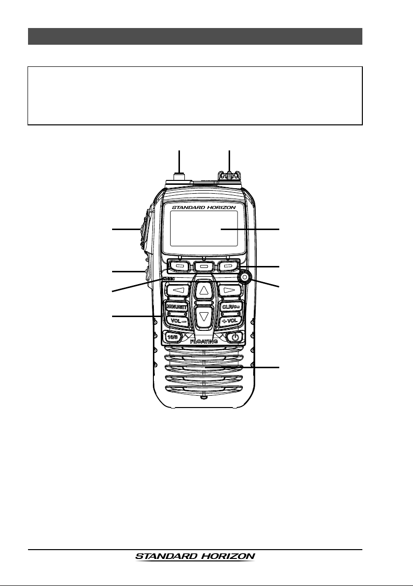
5.1 CONTROLS AND SWITCHES
NOTE
This section denes each control of the transceiver. For detailed operating
instructions, refer to section “6 BASIC OPERATION”. Refer to illustrations
for the location of the following controls, switches, and connections.
HX210
ANT Jack (Top Panel
À
The supplied CAT460 exible antenna is attached here.
)
PTT (PUSH-TO-TALK) Switch (Left Side Panel
Á
When pushed activates the transmitter.
SQL Switch
Â
Press this key to SQL adjustment.
Secondary use:
Press and hold this key to open the squelch, allowing you to monitor the
operating channel. Press the key to resume normal (quiet) monitoring.
Page 10
)
HX210
 Loading...