

MATRIX GX2000/GX2100
25 Watt VHF/FM
Marine Transceiver
Owner's Manual
Page 1GX2000S/GX2100S
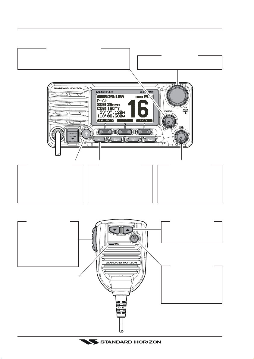
QUICK REFERENCE GUIDE I
You can do the basic operation in numerical order of the illustration below.
[
PWR/VOL] K
c
Press and hold this knob until the LCD
turns on, and adjust the audio level.
NOB
[CH]
K
d
Selects the operating channel.
NOB
[
16/9] B
g
y Press to recall chan-
nel 16.
y Press and hold to
recall channel 9.
[
PTT] S
h
Speak into the
microphone in a
normal voice level
while pressing this
switch.
UTTON
WITCH
M
ICROPHON
[
H/L] B
f
When pressed,
toggles the transmit
power between High
(25W) and Low (1W).
UTTON
[
SQL] K
e
Move this control
clockwise to squelch
or counter clockwise
un-squelch the radio.
[
TT
T] /
TT
d
Selects the operating
channel.
[
16/9] B
g
y Press to recall
channel 16.
y Press and hold to
recall channel 9.
NOB
[
SS
S] K
SS
UTTON
EY
GX2000/GX2100Page 2
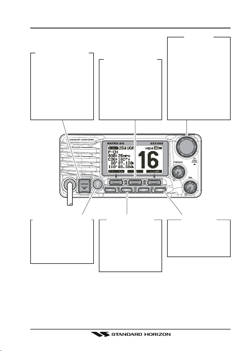
QUICK REFERENCE GUIDE II
[
DISTRESS] B
Note: for this key to
operate a MMSI must
be programmed.
Lift the red cover,
press the Distress button once, then press
and hold until the radio alarms.
UTTON
[
P
ROGRAMMABLE
These three keys
functions can be customized by the Setup
Menu mode.
The factory defaults
are [PA/FOG], [IC],
and [SCAN] key.
]
K
EY
[CH]
K
NOB
y Select the operating
channel.
y Select the item in
the “SETUP MENU”
and “DSC MENU”.
y When the “SETUP
MENU” or “DSC
MENU” is selected,
pressing this knob
saves a selection.
[
CALL/MENU] B
y Press to access the
“DSC MENU”.
y Press and hold to
access the “SETUP
MENU”.
UTTON
[
CLR/WX] B
y Press to cancel the
menu selection.
y Press and hold to
recall the last-used
NOAA Weather
Channel.
UTTON
[
AIS] B
UTTON
Press to change the
display to AIS (Automatic Identification
System) mode
Page 3GX2000/GX2100
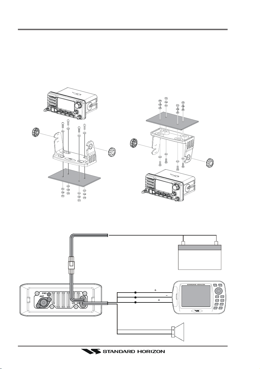
QUICK INSTALLATION GUIDE I
DESKTOP/OVERHEAD MOUNTING THE RADIO
The supplied universal mounting bracket allows desktop or overhead nounting.
Use a 13/64” (5.2-mm) bit to drill the holes to a surface which is more 0.4 inch
(10 mm) thick and can support more than 3.3 lbs (1.5 kg) and secure the
bracket with the supplied screws, spring washers, flat washers, and nuts.
DESKTOP MOUNTING OVERHEAD MOUNTING
ELECTRICAL CONNECTIONS
Red
12 V Battery
GPS Receiver
Plotter ConnectionRadio Wires
Purple
Green
Blue
( )
NMEA IN
NMEA COMMON
( )
NMEA OUT
Shield
White
( )
External Speaker
GX2000/GX2100Page 4
Black
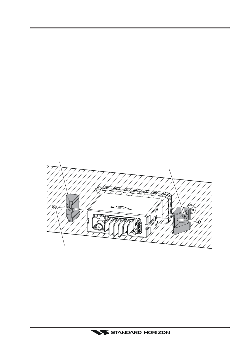
QUICK INSTALLATION GUIDE II
FLUSH MOUNTING THE RADIO
The optional MMB-84 Flush-Mount Bracket allows flush mounting the radio to
your vessel.
1. To assist in flush mounting, a template has been included. Use this template to assess the mounting location.
2. Use the template to mark the location where the rectangular hole is to be
cut. Confirm the space behind the dash or panel is deep enough to accommodate the transceiver (at least 6.7 inches or 17 cm deep).
There should be at least 1/2 inch (1.3 cm) between the transceiver’s heatsink
and any wiring, cables or structures.
3. Cut out the rectangular hole and insert the transceiver.
4. Fasten the brackets to the sides of the transceiver with the lock washer nut
combination; so that the mounting screw base faces the mounting surface.
5. Turn the adjusting screw to adjust the tension so that the transceiver is
tight against the mounting surface.
Bracket
Adjusting Screw
Lock-washer nut combination
FLUSH MOUNTING
Page 5GX2000/GX2100
1 GENERAL INFORMATION
1.1 INTRODUCTION
The STANDARD HORIZON GX2000/2100 is a VHF/FM Marine Transceiver
designed for use in the frequency range of 156.025 to 163.275 MHz. The
GX2000/2100 can be operated from 11 to 16 VDC and has a switchable RF
output power of 1 watt or 25 watts.
The GX2100 is equipped with the AIS (Automatic Identification System) receiver and its display program which enables to identify and avoid other large
vessels nearby your vessel. The GX2100 is equipped with the display program of the AIS too. Threrfore, the GX2000 also enables to identify and avoid
other large vessels nearby your vessel, if the AIS receiver (not supply) is
commected.
The GX2000/GX2100 is capable of DSC (Digital Selective Calling) Class D
operation and an Enhanced second station RAM+ mic (CMP30 remote-control speaker/microphone with display) or VH-310 Handset. Class D operation
allows continuous receiving of Digital Selective Calling functions on channel
70 even if the radio is receiving a call.
The GX2000/GX2100 operates on all currently-allocated marine channels
which are switchable for use with USA, International, or Canadian regulations.
It has an emergency channel 16 which can be immediately selected from any
channel by pressing the red [16/9] key. NOAA Weather channels can also be
accessed immediately by Press and holding the [CLR(WX)] key with channel
selection.
Other features of the GX2000/GX2100 include: 30W PA/Fog, multi-station
intercom, scanning, priority scanning, submersible speaker mic, high and low
voltage warning, and GPS repeatability.
2 PACKING LIST
When the package containing the transceiver is first opened, please check it
for the following contents:
y GX2000 or GX2100 Transceiver
y Mounting Bracket and attaching hardware
y Owner’s Manual
y Warning Sticker
y Power Cord
GX2000/GX2100Page 6
3 OPTIONS
MMB-84 ......................................................................... Flush-Mount Bracket
CMP30B/W ............... Remote-Access Microphone (RAM+ Mic, Black/White)
VH-310 ..................................................Remote Handset (available in Black)
CT-100 ............................................... 23-foot Extension Cable for RAM+ Mic
CVS2500 ...............................................................................Voice Scrambler
MLS-310 .............. 10W amplified External Speaker with on/off Volum control
MLS-300 ...................................................................... External Loudspeaker
101W ............................................................... Mini White Extension Speaker
220SW ..................................................................... 4.5” Round Hail/PA Horn
240SW ........................................................ 5” x 8” Rectangular Hail/PA Horn
MEK-4 .... Microphone Extension Kit (to remote front panel mic to rear panel)
4 SAFETY / WARNING INFORMATION
This radio is restricted to occupational use, work related operations only where
the radio operator must have the knowledge to control the exposure conditions of its passengers and bystanders by maintaining the minimum separation distance of 0.89 m (2.92 feet). Failure to observe these restrictions will
result in exceeding the FCC RF exposure limits.
Antenna Installation:
The antenna must be located at least 0.89 m (2.92 feet) away from passengers in order to comply with the FCC RF exposure requirements.
Lithium Battery Included:
This radio contains a Lithium Battery. At the end of radio’s useful life, under
various state and lows, it may be illegal to dispose of Lithium Battery into the
municipal waste stream. Check with your local solid waste officials for details
in your area for recycling options or proper disposal.
ON-LINE WARRANTY REGISTRATION
Please visit www.standardhorizon.com to register the GX2000/
GX2100 Marine VHF. It should be noted that visiting the Web site from
time to time may be beneficial to you, as new products are released
they will appear on the STANDARD HORIZON Web site.
PRODUCT SUPPORT INQUIRIES
If you have any questions or comments regarding the use of the
GX2000/GX2100, you can visit the STANDARD HORIZON Web site
to send an E-Mail or contact the Product Support team at 800-767-2450
M-F 7:00-5:00PST.
Page 7GX2000/GX2100

5 FCC RADIO LICENSE INFORMATION
Standard Horizon radios comply with the Federal Communication Commission (FCC) requirements that regulate the Maritime Radio Service.
5.1 STATION LICENSE
An FCC ship station license is no longer required for any vessel traveling in
U.S. waters (except Hawaii) which is under 20 meters in length. However, any
vessel required to carry a marine radio on an international voyage, carrying a
HF single side band radiotelephone or marine satellite terminal is required to
have a ship station license. FCC license forms, including applications for ship
(605) and land station licenses can be downloaded via the Internet at http://
www.fcc.gov/Forms/Form605/605.html. To obtain a form from the FCC, call
(888) 225-5322.
5.2 RADIO CALL SIGN
Currently the FCC does not require recreational boaters to have a Ship Radio
Station License. The USCG recommends the boats registration number and
the state to be used.
5.3 CANADIAN SHIP STATION LICENSING
You may need a license when traveling in Canada. If you do need a license
contact their nearest field office or regional office or write:
Industry Canada
Radio Regulatory Branch
Attn: DOSP
300 Slater Street
Ottawa, Ontario
Canada, KIA 0C8
5.4 FCC / INDUSTRY CANADA INFORMATION
The following data pertaining to the transceiver is necessary to fill out the license application.
Type Acceptance .........................................................................FCC Part 80
Output Power ............................................... 1 Watt (low) and 25 Watts (high)
Emission ......................................................................... 16K0G3E, 16K0G2B
Frequency Range .................................................... 156.025 to 163.275 MHz
FCC Type Number ................................................................... K6630443X3D
Industry Canada Type Approval ............................................ 511B-30443X3S
GX2000/GX2100Page 8
6 FCC NOTICE
NOTICE
Unauthorized changes or modifications to this equipment may void compliance with FCC Rules. Any change or modification must be approved
in writing by STANDARD HORIZON.
NOTICE
This equipment has been tested and found to comply with the limits for
a Class B digital device, pursuant to Part 15 of the FCC Rules. These
limits are designed to provide reasonable protection against harmful
interference in a residential installation. This equipment generates, uses
and can radiate radio frequency energy and, if not installed and used in
accordance with the instructions, may cause harmful interference to radio communications. However, there is no guarantee that interference
will not occur in a particular installation. If this equipment does cause
harmful interference to radio or television reception, which can be determined by turning the equipment off and on, the user is encouraged to
try to correct the interference by one or more of the following measures:
- Reorient or relocate the receiving antenna.
- Increase the separation between the equipment and receiver.
- Connect the equpmet into an outlet on a circuit different from that to
which the receiver is connected.
- Consult the dealer or an experienced radio/TV technician for help.
Page 9GX2000/GX2100

7 GETTING STARTED
7.1 ABOUT VHF RADIO
The radio frequencies used in the VHF marine band lie between 156 and 158
MHz with some shore stations available between 161 and 163 MHz. The marine VHF band provides communications over distances that are essentially
“line of sight” (VHF signals do not travel well through objects such as buildings,
hills or trees). Actual transmission range depends much more on antenna type,
gain and height than on the power output of the transmitter. On a fixed mount
25W radio transmission expected distances can be greater than 15 miles, for
a portable 5W radio transmission the expected distance can be greater than 5
miles in “line of sight”.
7.2 SELECTING AN ANTENNA
Marine antennas are made to radiate signals equally in all horizontal directions, but not straight up. The objective of a marine antenna is to enhance the
signal toward the horizon. The degree to which this is accomplished is called
the antenna’s gain. It is measured in decibels (dB) and is one of the major
factors in choosing an antenna. In terms of effective radiated power (ERP),
antennas are rated on the basis of how much gain they have over a theoretical
antenna with zero gain. A 3 foot, 3dB gain antenna represents twice as much
gain over the imaginary antenna.
Typically a 3 foot 3dB gain stainless steel whip is used on a sailboat mast. The
longer 8 foot 6dB fiberglass whip is primarily used on power boats that require
the additional gain.
GX2000/GX2100Page 10
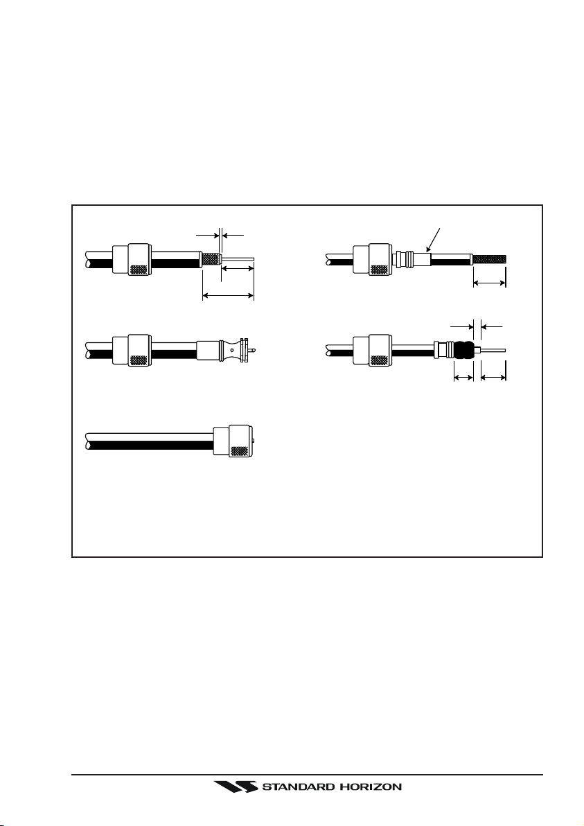
7.3 COAXIAL CABLE
VHF antennas are connected to the transceiver by means of a coaxial cable –
a shielded transmission line. Coaxial cable is specified by it’s diameter and
construction.
For runs less than 20 feet, RG-58/U, about 1/4 inch in diameter is a good
choice. For runs over 20 feet but less than 50 feet, the larger RG-8X or RG213/U should be used for cable runs over 50 feet RG-8X should be used. For
installation of the connector onto the coaxial cable refer to the figure below.
1/16''
3/4''
1 1/8''
Adapter
3/4''
1/8''
5/8''3/8''
To get your coax cable through a fitting and into your boat’s interior, you
may have to cut off the end plug and reattach it later. You can do this if
you follow the directions that come with the connector. Be sure to make
good soldered connections.
Page 11GX2000/GX2100

8 INSTALLATION
8.1 LOCATION
The radio can be mounted at any angle. Choose a mounting location that:
• is far enough from any compass to avoid any deviation in compass reading due to the speaker magnet
• provides accessibility to the front panel controls
• allows connection to a power source and an antenna
• has nearby space for installation of a microphone hanger
• the antenna must be mounted at least 3 feet from radio
Note: To insure the radio does not affect the compass or radios performance is
not affected by the antenna location, temporarily connect the radio in the desired location and:
a. Examine the compass to see if the radio causes any deviation
b. Connect the antenna and key the radio. Check to ensure the radio is
operating correctly by requesting a radio check.
8.2 MOUNTING THE RADIO
8.2.1 Supplied Universal Mounting Bracket
The supplied universal mounting bracket allows overhead or desktop mounting.
Use a 13/64” (5.2-mm) bit to drill the holes to a surface which is more 0.4 inch
(10 mm) thick and can support more than 3.3 lbs (1.5 kg) and secure the
bracket with the supplied screws, spring washers, flat washers, and nuts.
GX2000/GX2100Page 12
 Loading...