

Yaesu Musen 20575X50 Users manual
HF/VHF/UHF All Mode TrAnsceiVer
FT-991
operATing MAnUAl
YAESU MUSEN CO., LTD.
Tennozu Parkside Building
2-5-8 Higashi-Shinagawa, Shinagawa-ku, Tokyo 140-0002 Japan
YAESU USA
6125 Phyllis Drive, Cypress, CA 90630, U.S.A.
YAESU UK
Unit 12, Sun Valley Business Park, Winnall Close
Winchester, Hampshire, SO23 0LB, U.K.


Table of ConTenTs
Table of Contents ......................................................... 1
Accessories & Options ................................................. 3
Supplied Accessories ................................................ 3
Available Options ..................................................... 4
Adjusting the Clock .................................................. 5
Resetting the Microprocessor ................................... 5
Installation and Interconnections ............................... 6
Antenna Considerations ........................................... 6
About Coaxial Cable ................................................ 6
Grounding ................................................................. 7
Connection of Antenna and Power Cables ............... 8
Connection of Microphone and Headphone ............. 9
Key, Keyer, and Computer-Driven Keying
Interconnections ..................................................... 10
VL-1000 Linear Amplier Interconnections .......... 11
Interfacing to Other Linear Ampliers ................... 12
Front Panel Controls & Switches ............................. 13
Display Indications..................................................... 18
Rear Panel ................................................................... 21
MH-31A8J Microphone Switches ............................. 23
Optional FH-2 Switches ............................................. 24
Basic Operation: Receiving on Amateur Bands ...... 25
Operation on 60-Meter (5 MHz) Band (U.S. version
only) ....................................................................... 28
CLAR (Clarier) Operation ................................... 29
LOCK ..................................................................... 30
DIMMER ............................................................... 30
VFO COLOR ......................................................... 30
Band Stack Operation ............................................. 31
C.S (Custom Switch
Convenience Features ................................................ 31
SCOPE ................................................................... 32
More Frequency Navigation Techniques ............... 33
Receiver Operation (Front End Block Diagram
ATT (AttenuAtor
Interference Rejection ............................................... 35
IPO (Intercept Point Optimization
IF Noise Blanker (NB) Operation .......................... 37
CONTOUR Control Operation .............................. 38
IF SHIFT Operation (SSB/CW/RTTY/PKT
) .................................................................... 39
Modes
) .............................................. 31
) ... 34
) .................................................. 35
) ........................ 36
WIDTH (IF DSP Bandwidth) Tuning (SSB/CW/
RTTY/DATA Modes
NARROW (NAR) One-Touch IF Filter
Selection ................................................................. 41
IF NOTCH Filter Operation (SSB/CW/RTTY/
DATA/AM Modes
Digital NOTCH Filter (DNF) Operation ................ 43
Digital Noise Reduction (DNR) Operation ............ 43
Tools for Comfortable and Effective Reception ...... 44
RF Gain .................................................................. 44
Audio Peak Filter ................................................... 45
AGC (Automatic Gain Control
Adjustable Receiver Audio Filter ........................... 47
SSB/AM Mode Transmission .................................... 48
ATU Operation ....................................................... 50
Using the Automatic Antenna Tuner ........................ 50
About ATU Operation ............................................ 51
PArAmetric microphone equAlizer (SSB/Am/Fm
) ...................................................................... 52
mode
Enhancing Transmit Signal Quality ......................... 52
Using the Speech Processor (SSB Mode
Adjusting the SSB Transmitted Bandwidth (SSB
Mode) ..................................................................... 55
Voice Memory (SSB/AM/FM modes:
optional DVS-6 and FH-2
Transmitter Convenience Features .......................... 56
VOX (SSB/AM/FM Modes: Automatic TX/RX
Switching using Voice Control) ............................. 58
MONITOR (SSB/AM/FM modes
Split-Frequency Operation ..................................... 60
Setup for Straight Key (and Straight Key emulation)
Operation ................................................................ 61
CW Mode Operation ................................................. 61
Using the Built-in Electronic Keyer ....................... 62
CW Spotting (Zero-Beating
CW Convenience Features ........................................ 65
CW Delay Time Setting ......................................... 66
Contest Memory Keyer (Using the Optional FH-2
Remote Control Keypad) ....................................... 67
Basic Operation ...................................................... 72
) ............................................. 40
) ................................................. 42
) ............................. 46
) .............. 54
Requires
) ................................ 56
) ......................... 59
) .................................. 65
F
T-991
OperaTing Manual
Page 1

Table of ConTenTs
FM Mode Operation .................................................. 72
Repeater Operation ................................................. 73
Tone Squelch Operation ......................................... 74
Memory Operation .................................................... 75
Convenient Memory functions ............................... 75
QMB (Quick Memory Bank
Standard Memory Operation .................................. 76
Memory Groups ..................................................... 80
Operation on Alaska Emergency Frequency: 5167.5
khz (U.S. Version Only) ............................................. 81
VFO and Memory Scanning ..................................... 82
VFO Scanning ........................................................ 82
Memory Scan ......................................................... 83
PMS (Programmable Memory Scanning) ............... 84
RTTY (Radio Teletype) Operation ........................... 85
Example of Connecting RTTY Communications
Device ..................................................................... 85
DATA (PSK) Operation ............................................. 86
Example of Data Communications Device ........... 86
Menu Mode ................................................................. 87
Specications .............................................................. 91
) ................................. 75
Page 2
F
T-991
OperaTing Manual

Supplied AcceSSorieS
Hand Microphone
DC Power Cord 1 pc T9025225
Spare Fuse (
Operating Manual 1 pc
Warranty Card 1 pc
(
MH-31
) 1 pc Q0000074
25A
)
A8J
1 pc A07890001
aCCessories & opTions
F
T-991
OperaTing Manual
Page 3
Accessories & options
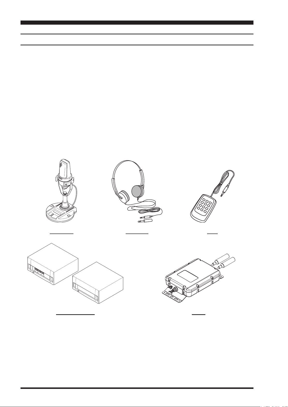
AvAilAble OptiOns
A8X
MD-200
MD-100
YH-77STA
FH-2
VL-1000/VP-1000
FC-40
FP-1030A
CT-118
CT-39A
CTCable(MDIN10P-BareWire2m) LinearAmplierConnectionCable(P/NT9207451)
Ultra-High-Fidelity Desktop Microphone
A8X
Desktop Microphone
Lightweight Stereo Headphone
Remote Control Keypad
LinearAmplier/ACPowerSupply
ExternalAutomaticAntennaTuner
ExternalPowerSupply(13.8VDC25A)
PacketInterfaceCable
VL-1000
LinearAmplierConnectionCable
MD-200
A8X
VL-1000/VP-1000 FC-40
YH-77STA FH-2
Page 4
F
T-991
OperaTing Manual
before You begin
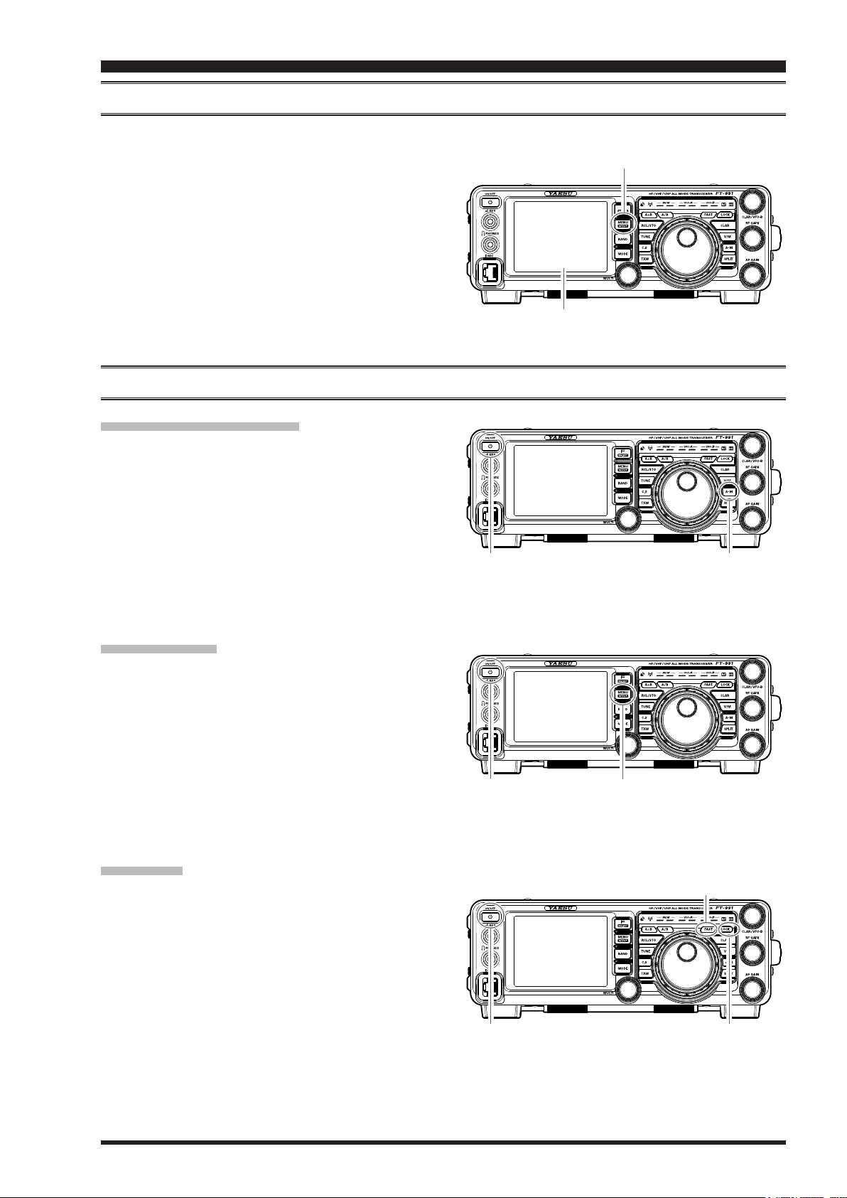
AdjuSting the clock
Use the following procedure to adjust the clock shown at the top right of the LCD display.
1. Press and hold the
2. Touch [
3. Enter the present time with the number keys on the
LCD, then touch [
4. Touch [
5. Enter month, day, and year with the number keys on
the LCD, then touch [
6. Touch [
mode display.
7. Press the
radio operation display.
TIME/DATE
DATE
BACK
MENU(SETUP)
MENU(SETUP)
] on the LCD.
].
ENT
] on the LCD to switch the screen.
].
ENT
] on the LCD to return to the setup
button to return to the
button.
reSetting the MicroproceSSor
reSetting MeMorieS (only
Use this procedure to reset (clear) the previously stored
Memory channels, without affecting any conguration
changes you may have made to the Menu settings.
1. Press the front panel
transceiver off.
2. While holding the
in the front panel
ceiver on. Once the transceiver comes on, you may
release the buttons.
A
ON/OFF
)
ON/OFF
M
switch to turn the
button in, press and hold
switch to turn the trans-
ON/OFF switch
MENU(SETUP)
LCD
button
AM button
Menu reSetting
Use this procedure to restore the Menu settings to their
factory defaults, without affecting the memories you
have programmed.
1. Press the front panel
transceiver off.
2. While holding the
and hold in the front panel
the transceiver on. Once the transceiver comes on,
you may release the buttons.
ON/OFF
MENU(SETUP)
switch to turn the
button in, press
ON/OFF
switch to turn
Full reSet
Use this procedure to restore all Menu and Memory settings to their original factory defaults. All Memories will
be cleared by this procedure.
1. Press the front panel
transceiver off.
2. While holding the
press and hold in the front panel
turn the transceiver on. Once the transceiver comes
on, you may release the buttons.
ON/OFF
FAST
switch to turn the
and
LOCK
ON/OFF
buttons in,
switch to
ON/OFF switch MENU(SETUP) button
ON/OFF switch
FAST button
LOCK button
F
T-991
OperaTing Manual
Page 5
insTallaTion and inTerConneCTions
AntennA conSiderAtionS
The
FT-991
ing frequency. While minor excursions from the 50-Ohm specication are of no consequence, if the Standing Wave Ratio (SWR) present at the Antenna jack is greater than 3:1, the transceiver’s Automatic Antenna Tuner may not be able to
reduce the impedance mismatch to an acceptable value.
Every effort should be made to ensure that the impedance of the antenna system be as close as possible to the specied
50-Ohm value. Note that the “G5RV” type antenna does not provide a 50-Ohm impedance on all HF Amateur bands. An
external wide-range antenna coupler must be used with this antenna type.
is designed for use with any antenna system providing a 50 Ohm resistive impedance at the desired operat-
Any antenna to be used with the
using a “balanced” antenna such as a dipole, remember that a balun or other matching/balancing device must be used to
ensure proper antenna performance.
The same precautions apply to any additional (receive-only) antennas connected to the antenna jacks. if your receiveonly antennas do not have impedance near 50 Ohms at the operating frequency, you may need to install an external antenna tuner to obtain optimum performance.
FT-991
must be fed from the transceiver with 50 Ohm coaxial cable. Therefore, when
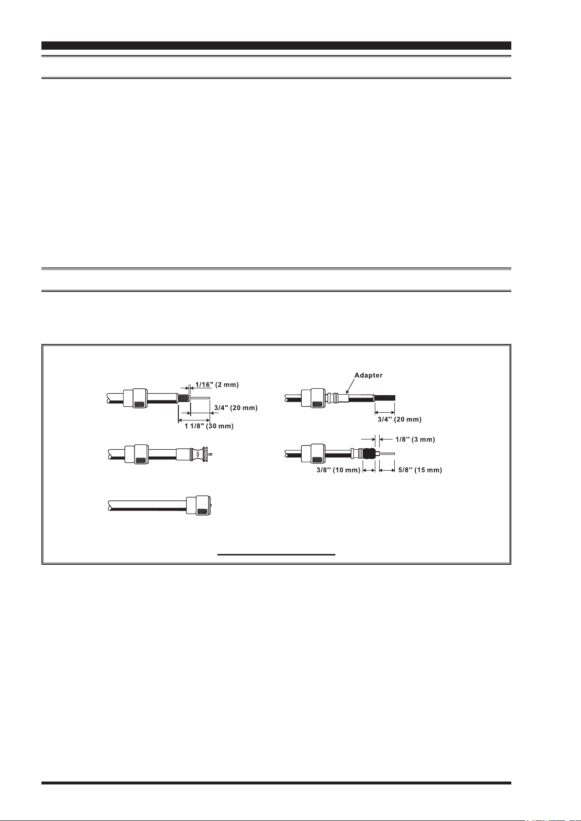
About coAxiAl cAble
Use high-quality 50-Ohm coaxial cable for the lead-in to your
antenna system will be wasted if poor quality, lossy coaxial cable is used. This transceiver utilizes standard “M” (“PL259”) type connectors.
FT-991
transceiver. All efforts at providing an efcient
Page 6
typicAl pl-259 inStAllAtion
F
T-991
OperaTing Manual
insTallaTion and inTerConneCTions
GND
Transceiver
GND
Linear
Amplifier
GND
TNC
"Daisy Chain"
GND
Linear
Amplifier
GND
TNC
GND
Transceiver
GND
Transceiver
GND
Linear
Amplifier
GND
TNC
"Daisy Chain"
grounding
The
FT-991
mum electrical safety and best communications effectiveness. A good ground system can contribute to station efciency
in a number of ways:
It can minimize the possibility of electrical shock to the operator.
It can minimize RF currents owing on the shield of the coaxial cable and the chassis of the transceiver. such cur-
rents may lead to radiation, which can cause interference to home entertainment devices or laboratory test equipment.
It can minimize the possibility of erratic transceiver/accessory operation caused by RF feedback and/or improper
current ow through logic devices.
An effective earth ground system may take several forms. for a more complete discussion, see an appropriate RF engineering text. The information below is intended only as a guideline.
Typically, the ground connection consists of one or more copper-clad steel rods, driven into the ground. If multiple
ground rods are used, they should be positioned in a “V” conguration and bonded together at the base of the “V” which
is nearest the station location. Use a heavy, braided cable (such as the discarded shield from type RG-213 coaxial cable)
and strong cable clamps to secure the braided cable(s) to the ground rods. Be sure to weatherproof the connections
to ensure many years of reliable service. Use the same type of heavy, braided cable for the connections to the station
ground bus (described below).
transceiver, like any other HF communications apparatus, requires an effective ground system for maxi-
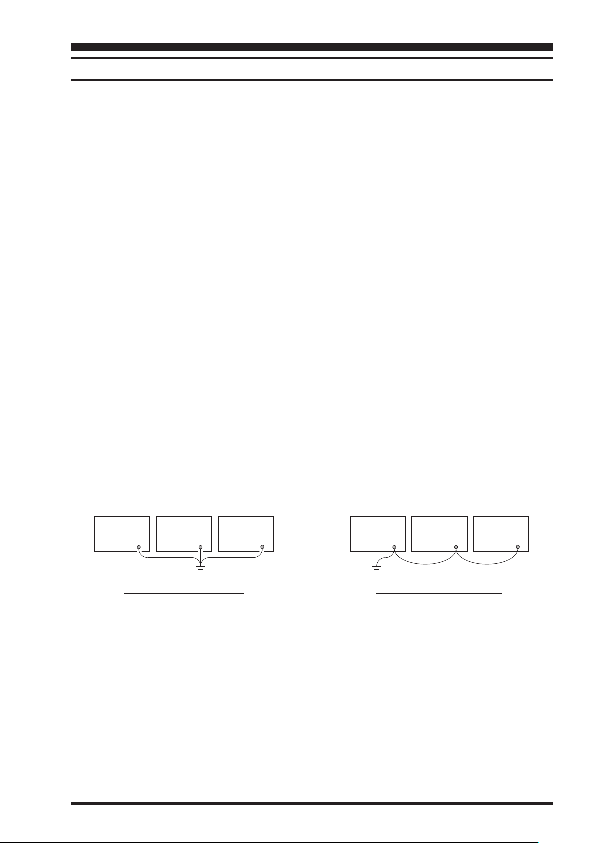
Inside the station, a common ground bus consisting of a copper pipe of at least 25 mm diameter should be used. An alternative station ground bus may consist of a wide copper plate (single-sided circuit board material is ideal) secured to
the bottom of the operating desk. Grounding connections from individual transceivers, power supplies, and data communications devices (TNCs, etc.) should be made directly to the ground bus using a heavy, braided cable.
Do not “Daisy-Chain” ground connections from one electrical device to another and thence to the ground bus. This
method may nullify any attempt at effective radio frequency grounding. See the drawing below for examples of proper
grounding techniques.
Inspect the ground system - inside the station as well as outside - on a regular basis to ensure continued performance
and safety.
Besides following the above guidelines carefully, note that household or industrial gas lines must never be used in an
attempt to establish an electrical ground. Cold water pipes may, in some instances, help in the grounding effort, but gas
lines represent a signicant explosion hazard, and must never be used.
proper ground connection
iMproper ground connection
F
T-991
OperaTing Manual
Page 7
insTallaTion and inTerConneCTions
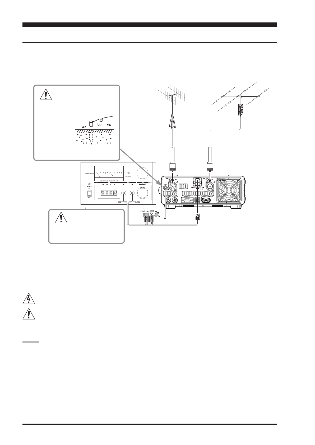
connection oF AntennA And power cAbleS
Please follow the outline in the illustration regarding the proper connection of antenna coaxial cables, as well as the DC
power cable. The DC power connector for the
%), and capable of at least 23 Amperes of current. Always observe proper polarity when making DC connection:
The RED DC power lead connects to the Positive (+) DC terminal.
The BLACK DC power lead connects to the Negative (–) DC terminal.
To prevent damage from
lightning, atmospheric electricity, electrical shock etc., please
provide a good earth ground.
Use a short,
thick, braided
cable to connect your station
equipment to the
buried ground rod (or alternative earth
ground system).
FT-991
must only be connected to a DC source providing 13.8 Volts DC (±10
Check the DC volt-
age and current rating
(+13.8 V, 23 A) of the power
supply before connecting to the
transceiver.
We recommend the use of the
be used with the
lines described above must be strictly followed.
Note that other manufacturers may use the same type of DC power connections as does your
ever, the wiring conguration may be different from that specied for your transceiver. Serious damage can be caused if
improper DC connections are made; consult with a qualied service technician when in doubt.
The 100 V RF voltage (@100 W/50-ohm) is applied to the TX RF section of the transceiver while transmitting.
Do not touch the TX RF section absolutely while transmitting.
Permanent damage can result when improper supply voltage, or reverse-polarity voltage, is applied to the
991
verse polarity DC, or DC voltage outside the specied range of 13.8 V ±10 %. When replacing fuses, be certain to use a
fuse of the proper rating. The
Advice:
Do not position the
Do not position the
Ensure adequate ventilation around the
to high heat.
Do not install the
To minimize the possibility of interference to home entertainment devices, take all precautionary steps including
separation of TV/FM antennas from Amateur transmitting antennas to the greatest extent possible, and keep transmitting coaxial cables separated from cables connected to home entertainment devices.
Ensure that the DC power cord is not subject to undue stress or bending, which could damage the cable or cause it to
be accidentally unplugged from the rear panel
Be certain to install your transmitting antenna(s) so they cannot possibly come in contact with TV/FM radio or other
antennas, or with power or telephone lines.
FT-991
. The Limited Warranty on this transceiver does not cover damage caused by application of AC voltage, re-
FT-991
FT-991
FT-991
FP-1030A
, but the 13.8 VDC input voltage, 23 Ampere current capability, and DC cable polarity guide-
FT-991
in a location with direct exposure to sunshine.
in a location exposed to dust and/or high humidity.
on an unstable desk or table. Do not place in a location where objects may fall onto it from above.
(USA market only) AC Power Supply. Other models of power supplies may
transceiver, how-
requires a 25 A blade fuse.
FT-991
, to prevent heat build-up and possible reduction of performance due
jack.
DC IN
FT-991
FT-
Page 8
F
T-991
OperaTing Manual
insTallaTion and inTerConneCTions
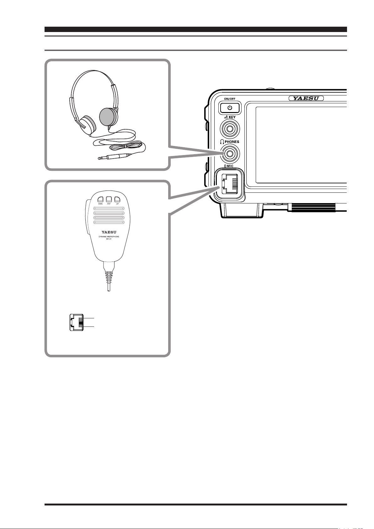
connection oF Microphone And heAdphone
DOWN
UP
+5V
MIC GND
MIC
PTT
GND
FAST
F
T-991
OperaTing Manual
Page 9
insTallaTion and inTerConneCTions
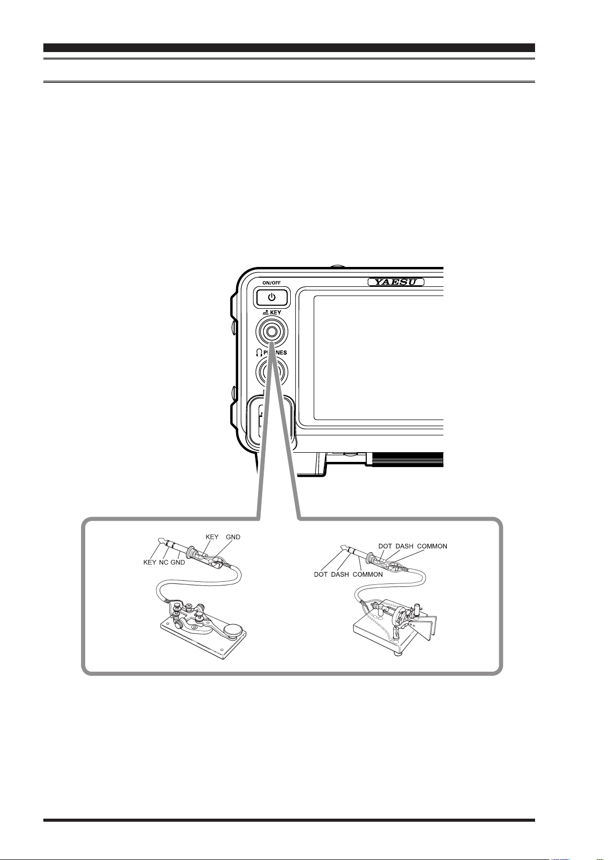
key, keyer, And coMputer-driven keying interconnectionS
The
FT-991
later. Besides the built-in Electronic Keyer, two key jacks are provided, one on the front and one on the rear panel, for
convenient connection to keying devices.
includes many features for the CW operator. These functions will be detailed in the “Operation” section
The Menu selections allow you to congure the front panel
example, you may connect your keyer paddle to the front panel
paddle input.
The
down current is approximately 4 mA. When connecting a key or other device to the
(“stereo”) 1/4” phone plug; a 2-contact plug will place a short between the ring and (grounded) shaft of the plug, resulting in a constant “key-down” condition in some circumstances.
jack on the
KEY
FT-991
utilize “Positive” keying voltage. Key-up voltage is approximately +3.3V DC, and key-
jack according to the device you wish to connect. For
KEY
jack, and use Menu item “
KEY
KEY
018 F KEYER TYPE
jack, use only a 3-contact
” for
Page 10
F
T-991
OperaTing Manual
insTallaTion and inTerConneCTions
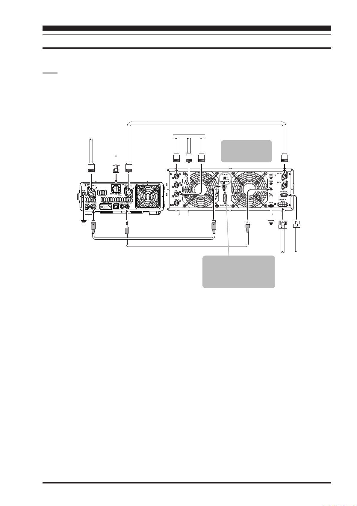
vl-1000 lineAr AMpliFier interconnectionS
Be sure that both the
FT-991
in the illustration.
note:
Refer to the
Do not attempt to connect or disconnect coaxial cables when your hands are wet.
VL-1000
and
VL-1000
are turned off, and then follow the installation recommendations contained
Operating Manual for details regarding amplier operation.
Coaxial Cable (50Ω)
Connect to “INPUT 1” of the VL-1000
144/430MHz Antenna
DC 13.8 V
ANT
144/430MHz
GND
TUN/LIN
INPUT
ANT
HF/50MHz
REM/ALC
CT-58 Band Data Cable (Option)
HF/50MHz Antenna
ANT 1
ANT 2
ANT 3
CT-58 ALC Cable (Option)
To link the FT-991 and VL-
1000 Power switches, set the
VL-1000 REMOTE switch to
the “ON” position.
Set the front panel’s
INPUT switch to the
“INPUT1”.
ALC 1
BAND-DATA 1
GND
INPUT 1
VP-1000
CONTROL
DC 48V IN
VP-1000
F
T-991
OperaTing Manual
Page 11
 Loading...