

Yaesu Musen 20445X20 Users manual

C4FM FDMA 144/430 MHz
FCCID:K6620445X20
IC:511B-20445X20
YAESUMUSENCO.,LTD.
DUAL BAND DIGITAL TRANSCEIVER
FT1DR
OPERATING MANUAL
YAESU MUSEN CO., LTD.
Tennozu Parkside Building
2-5-8 Higashi-Shinagawa, Shinagawa-ku, Tokyo 140-0002 Japan
YAESU USA
6125 Phyllis Drive, Cypress, CA 90630, U.S.A.
YAESU UK LTD.
Unit 12, Sun Valley Business Park, Winnall Close
Winchester, Hampshire, SO23 0LB, U.K.
YAESU HK LTD.
Unit 1306-1308, 13F., Millennium City 2, 378 Kwun Tong Road,
Kwun Tong, Kowloon, Hong Kong

Before Reading This Manual
FCCID:K6620445X20
IC:511B-20445X20
YAESUMUSENCO.,LTD.
Contents
Before Reading This Manual ................................... 2
Introduction ................................................................. 4
Features of FT1DR ................................................ 4
How to Read This Manual ...................................... 5
Checking Bundled Items ........................................ 5
Safety Precautions (Be Sure to Read) ....................... 6
Names and Functions of Controls ............................ 12
Basic Operation ...................................................... 15
Preparation ............................................................... 15
Installing the Antenna........................................... 15
Attaching the Supplied Belt Clip/Protective Cap
............................................................................. 15
Attaching the Protective Cap ........................... 15
Installing the Belt Clip ...................................... 15
Attaching a Hand Strap ........................................ 16
How to Use the Battery Case (FBA-39) (Option)
............................................................................. 16
Before Reading This Manual
Installing/Removing the Battery Pack .................. 17
Installing the Battery Pack ............................... 17
Removing the Battery Pack ............................. 17
Charging the Battery Pack ................................... 18
Connecting an External Power Supply for Use in
Vehicle ................................................................. 20
Connecting to an External Power Supply Using a
Power Cable ........................................................ 21
Communication......................................................... 23
Turning on the Power ........................................... 23
Adjusting the Volume Level.................................. 24
Selecting an Operating Band ............................... 25
Selecting a Frequency Band ................................ 27
Tuning in to a Frequency ..................................... 28
Performing Communication ................................. 29
Listening to the Radio ............................................... 30
Listening to an AM or FM Broadcast .................... 30
To deactivate the radio function ...................... 31
To scan through the radio band ....................... 31
Switching between AM Antennas ......................... 31
Miscellaneous Settings ............................................. 32
Setting the Date and Time ................................... 32
Setting the Time Signal ........................................ 33
Muting Audio ........................................................ 33
Changing the Transmission Power Level............. 34
Adjusting the Squelch Level................................. 35
Changing the Frequency Step Manually .............. 35
Changing the Mode Manually .............................. 36
Locking keys or switches ..................................... 37
Restoring to Defaults (All Reset).......................... 37
Repeater Operation ................................................ 38
Repeater Operation .................................................. 38
Communicating Via the Repeater ........................ 38
Using the Memory .................................................. 39
A Wide Variety of Memory Functions ........................ 39
Writing into the Memory ....................................... 40
Split Memory ........................................................ 41
Recalling a Memory Channel ............................... 41
Recalling the Home Channel ............................... 42
Returning to the Previous Frequency .............. 42
Deleting the Memory Channel ............................. 42
Restoring the Deleted Memory Channel ......... 43
Using Memory Banks ............................................... 43
Registering a Memory Channel in a Memory
Bank ..................................................................... 44
Recalling a Memory Bank .................................... 44
Canceling Memory Channel Registration in a
Memory Bank ...................................................... 45
Convenient Special Banks ....................................... 45
Registering Your Favorite Special Memory
Channels in a Memory Bank ................................ 45
Recalling a Special Bank to Listen to the JR
Railway Radio ...................................................... 46
Recalling a Special Bank to Listen to the
International VHF (Marine) Radio ........................ 46
Scanning Function ................................................. 48
Using the Scanning Function.................................... 48
VFO Scan ............................................................ 48
Canceling Scanning ........................................ 49
Skipping a Frequency You Do Not Want Scan
(Skip Search Memory) .................................... 49
Specifying the Frequency You Do Not Want to
Scan ................................................................ 50
Deleting a Frequency Saved in the Skip Search
Memory ........................................................... 50
Selecting a Reception Method When Scanning
Stops ............................................................... 51
Memory Scanning ................................................ 51
Specifying a Skip/Selected Memory Channel
........................................................................ 53
Scanning Only the Selected Memory
Channel ........................................................... 54
Scanning a Memory Bank .................................... 54
Memory Bank Link Scan ................................. 55
Programmable Memory Scan (PMS) ................... 56
Writing into a Programmable Memory ............. 56
Performing Programmable Memory Scan ....... 56
Using the Search Function ....................................... 57
Spectrum Scope Searching for a Signal
Using a Signal Strength Graph ....................... 57
Using the GPS Function ........................................ 58
What is GPS? ........................................................... 58
Activating the GPS Function..................................... 58
Method of Positioning by GPS.................................. 59
Explanation of GPS Screen and Operation .............. 61
BACK TRACK Function ............................................ 62
Causing the FT1DR to Memorize the Current
Point ..................................................................... 62
Using the BACK TRACK Function ....................... 63
Description of the BACK TRACK Function Screen
............................................................................. 63
2

Useful Functions .................................................... 64
FCCID:K6620445X20
IC:511B-20445X20
YAESUMUSENCO.,LTD.
Dual Reception (DW) Functions ............................... 64
Dial Dual Reception
VFO mode Priority memory channel ........................ 64
Memory Dual Reception
Memory channel Priority memory channel ................ 65
Home Channel Dual Reception
Home channel Priority memory channel .................. 65
Using the DTMF Function......................................... 66
Confirming the Entered DTMF Code by the
Sound .............................................................. 67
Sending the Registered DTMF Code ................... 67
Sending a DTMF Code Manually ......................... 68
Communicating with a Specific Remote Station
.................................................................................. 69
Using the Tone Squelch Function ............................. 69
Selecting a Tone Frequency ............................ 70
Selecting a DCS Code .................................... 71
Searching for the Frequency of the DCS Used
by the Remote Station ..................................... 72
Notification of Call from the Remote Station by
Vibration of the Vibrator ....................................... 73
Selecting a Vibrator Operation Mode .............. 73
Notification of Call from a Remote Station by the
Bell Bell Function ................................................. 74
Changing the Number of Times the Bell
Rings ............................................................... 75
Calling Only a Specific Station New Pager
Function ............................................................... 75
Flow of Operation to Use the Pager Function
........................................................................ 76
Setting the Code of Your Station ..................... 76
Turning on the New Pager Function ................ 77
Calling a Specific Station ................................ 77
Being Called by the Remote Station
(Standby Operation) ........................................ 78
Functions Used As Needed ................................... 79
Set Mode .................................................................. 79
Selecting Set Mode Items .................................... 79
Resetting the Set Mode Items ......................... 79
Set Mode Item List .............................................. 80
FT1DR Specifications............................................. 87
Contents
Before Reading This Manual
3

Introduction
FCCID:K6620445X20
IC:511B-20445X20
YAESUMUSENCO.,LTD.
Features of FT1DR
Digital communication (C4FM (Quaternary FSK), FDMA system) ...........................000
External power supply terminal ................................................................................ 000
Reception on two different bands + Reception on two identical bands (V+V/U+U) . 000
Independent switching keys for A-band and B-band and TX/BUSY display ............ 000
Wide-band reception over the range of 500 kHz to 999.900 MHz ........................... 000
Waterproofing design 20 conforming to IPX5, which protects the FT1DR from
rain and splashes ..................................................................................................... 000
Independent side keys, a full keyboard for easy entry of data,
and a tilted main dial. .............................................................................................. 000
Easy-to-see dot matrix display ................................................................................. 000
Ready for WiRES-II and WiRES-X connection (realized by the incorporated
Before Reading This Manual
64-channel WiRES-II access memory) .............................................Refer to CD-ROM.
Large-capacity 1327 ch memory and twenty-four 100 ch memory banks ............... 000
Display of a memory tag comprising up to 16 one-byte characters ......................... 000
Special banks for easy reception ............................................................................. 000
Just by selecting preset frequencies, you can receive AM/FM, shortwave broadcast,
international VHF radios with ease. ........................................................................ 000
A wide variety of scan functions ............................................................................... 000
Built-in GPS unit allowing display of your current location and
heading information .................................................................................................000
Ready for APRS
1200/ 9600bps AX25 modem (B-band only) ........................................... See CD-ROM.
High-resolution spectrum scope function for ±50 channels ....................................000
A variety of individual calling functions such as tone squelch (CTCSS) and DCS
functions .................................................................................................................. 000
Vibrator for informing you of signal reception in addition to the bell ....................... 000
New pager function for calling only specific stations ................................................ 000
Illumination by white LED for easy viewing of the LCD outdoors ............................ 000
Built-in temperature sensor ...................................................................................... 000
Battery save function for prolonging the operating time of the battery ..................... 000
Data terminal for data communication with external equipment or
firmware update ....................................................................................................... 000
Build-in bar antenna for AM reception ..................................................................... 000
Ready for micro SD ................................................................................................. 000
Snapshot function (an optional camera microphone MH-85A11U is required)
................................................................................................................ See CD-ROM.
®
communication through use of world standard
4
How to Read This Manual
FCCID:K6620445X20
IC:511B-20445X20
YAESUMUSENCO.,LTD.
Typical explanatory expressions used in this manual are as follows:
Press the B key briefly.
Press and hold the B key for over 1 second.
FB... (Press the F key, and then press the B key.)
While pressing the v key, turn the O knob.
Precaution
...Explains notes to follow during operation.
Hint
Introduction
...Explains operating suggestions or useful hints.
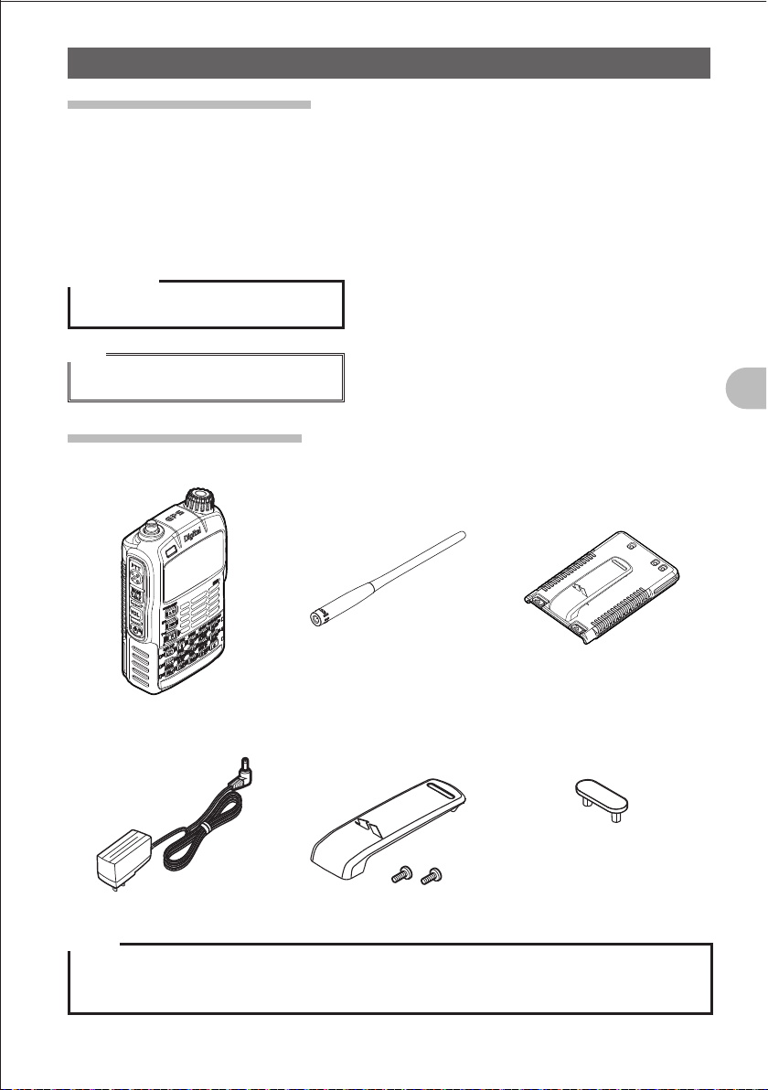
Checking Bundled Items
Main unit Antenna Battery pack (FNB-101LI)
Battery charger (PA-48) Belt clip Protective plate for battery
pack
• Operating Instruction
(this manual)
• Warranty
Before Reading This Manual
Notes
z Make sure that the name of the shop from which you purchased the product and the date of
purchase are indicated on the warranty card.
z If any item is missing, contact the shop from which you purchased the product.
5
Safety Precautions (Be Sure to Read)
FCCID:K6620445X20
IC:511B-20445X20
YAESUMUSENCO.,LTD.
Safety Precautions (Be Sure to Read)
Be sure to read the safety precautions to use this product safely.
We are not liable for failures and other problems caused due to misuse or use of this
product by you or a third party as well as the damages caused through use of this
product by you or a third party except in the case where we are ordered to pay for
damages under the laws.
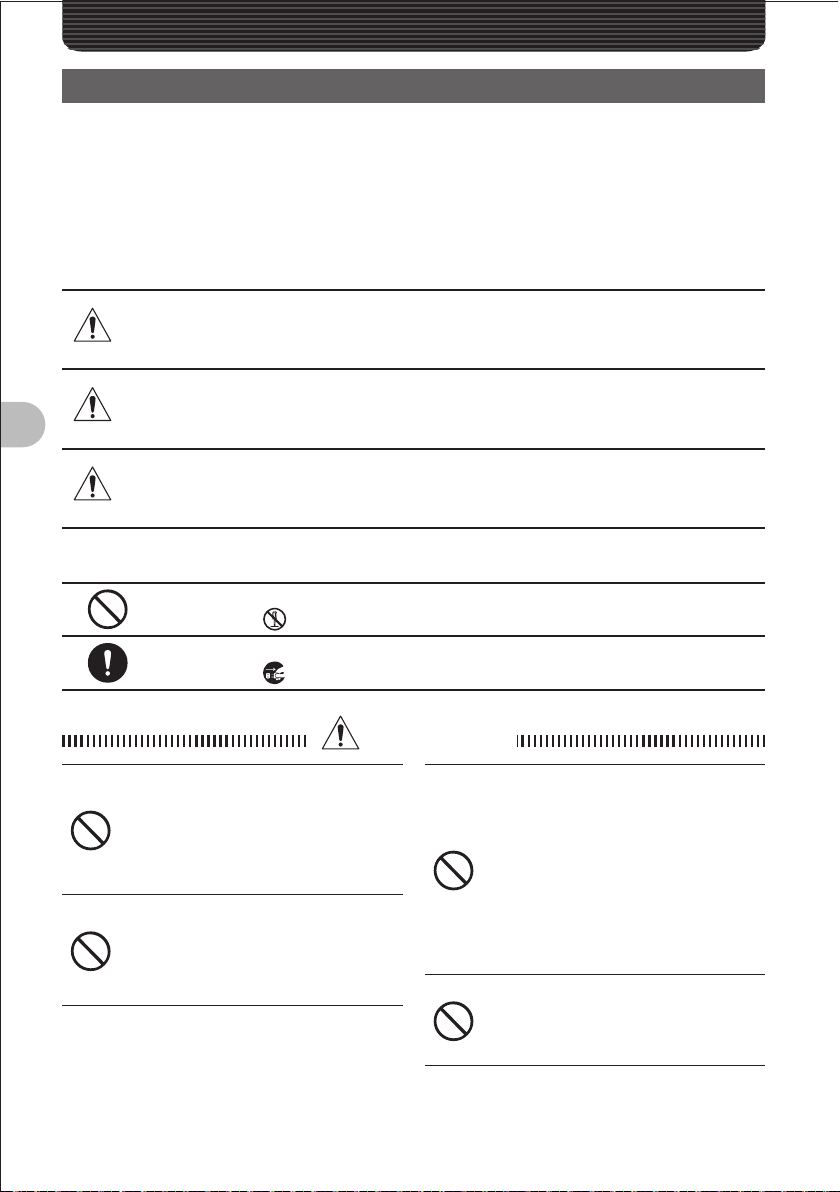
Types and Meanings of Symbols
DANGER
WARNING
Before Reading This Manual
CAUTION
Types and Meanings of Legends
Indicates a prohibited item not to be done in order to use this product safely.
For example,
Indicates an obliged item to be done in order to use this product safely.
For example,
Do not use this product in “an area
where use of it is prohibited”, e.g.,
inside the hospital, airplane, or
train.”
This product can affect electronic or
medical devices.
Do not use this product while riding
a bicycle or driving a car. Accidents
can result.
Be sure to stop the bicycle or car at a
safe place before using this product.
Indicates an imminently hazardous situation which, if not
avoided, could result in death or serious injury.
Indicates a potentially hazardous situation which, if not
avoided, could result in death or serious injury.
Indicates a potentially hazardous situation which, if not
avoided, may result in minor or moderate injury or only
property damage.
indicates that the product should not be disassembled.
indicates that the power plug should be removed.
DANGER
Those who are carrying a medical
device such as a cardiac pacemaker
should not perform transmission
near it. When performing
transmission, use an external
antenna and keep away from the
external antenna as far as possible.
The radio wave emitted from this
product can cause the medical device
to malfunction and result in an accident.
Do not use this product or the
battery charger in a place where
inflammable gas is generated.
A fire or explosion can occur.
6
Safety Precautions (Be Sure to Read)
FCCID:K6620445X20
IC:511B-20445X20
YAESUMUSENCO.,LTD.
Do not perform transmission in a
crowded place for the safety of the
persons carrying a medical device
such as a cardiac pacemaker.
The radio wave emitted from this
product can cause the medical device
to malfunction and result in an accident.
Do not touch the liquid leaking from
the battery pack with bare hands.
The liquid that has stuck to your skin or
entered in your eye can cause chemical
burn. In such a case, consult the doctor
immediately.
WANING
Do not use this product at a voltage
other than the specified power
supply voltage.
A fire or electric shock can result.
Do not use the battery pack for any
model other than the specified mode.
A fire, leak, overheating, explosion, or
ignition can result.
This product has a waterproof
structure and conforms to “IPX5”
when the included antenna and
battery pack are installed and rubber
caps are securely attached to the
MIC/SP jack, EXTDC IN jack, DATA
terminal, and micro SD slot. If this
product gets wet, wipe it with a dry
cloth, etc. without leaving it as it is.
Leaving this product in a wet condition
can degrade its performance, shorten
its life, or cause a failure or electrical
shock.
Do not perform transmission for a
long period.
The main body can overheat, resulting
in a failure or burn.
Do not disassemble or make any
alteration to this product.
An injury, electric shock, or failure can
result.
Do not solder or short-circuit the
terminal of the battery pack.
A fire, leak, overheating, explosion, or
ignition can result.
Do not carry the battery pack together
with a necklace or hair pin. A short
circuit can result.
If it starts thundering when
the external antenna is used,
immediately turn off this product
and disconnect the external antenna
from it.
A fire, electrical shock, failure can
result.
Before Reading This Manual
Do not handle the battery pack or
charger with wet hands. Do not
insert or remove the power plug with
wet hands.
An injury, leak, fire, or failure can result.
If smoke or strange odor is emitted
from the main body, battery pack,
or battery charger, immediately turn
off this product, remove the battery
pack, and remove the power plug
from the outlet.
A fire, leak, overheating, damage,
ignition, or failure can result. Contact
the shop from which you purchased
this product or our Amateur Customer
Support.
Do not use the battery pack which is
externally damaged or deformed.
A fire, leak, hating, explosion, or ignition
can result.
Do not use any battery charger
which is not specified by us.
A fire or failure can result.
Keep the terminals of the battery
pack clean.
If stained, a fire, leak, overheating,
explosion, or ignition can result.
7
Safety Precautions (Be Sure to Read)
FCCID:K6620445X20
IC:511B-20445X20
YAESUMUSENCO.,LTD.
If charging of the battery pack
cannot be completed after lapse
of the specified time, immediately
remove the power plug of the battery
charger from the outlet.
A fire, leak, overheating, explosion, or
ignition can result.
CAUTION
Before Reading This Manual
Do not dangle or throw this product
by holding its antenna.
This product can hit and injure
someone. In addition, doing so can
result in a main body failure or damage.
Do not use this product in a crowded
place.
The antenna can hit someone, resulting
in a injury.
Do not place this product in a place
subject to direct sunlight or near a
heater.
This product can deform or discolor.
Do not place this product in a humid
or dusty place.
A fire or failure can result.
During transmission, keep the
antenna away from you as far as
possible.
Long-time exposure to electromagnetic
waves can have a negative impact on
your health.
Do not clean the case with thinner or
benzene.
Use a soft, dry cloth to clean the case.
If you do not use this product for a
long period, turn it off and remove
the battery pack for safety.
Do not give a strong shock to or
throw this product.
A failure can result.
Keep magnetic cards and video tape
away from this product.
The data recorded on cash cards or
video tape can be erased.
Do not use the earpiece microphone,
earphones, or headphones at an
extremely high volume level.
Hearing impairment can result.
Keep this product out of reach of
children.
An injury, etc. can result.
Install the hand strap and belt click
securely.
If they are installed improperly, they
can fall down, resulting in an injury or
damage.
Do not place a heavy thing on the
power cord of the battery charger.
The battery cord can be damaged,
resulting in a fire or electric shock.
Do not use the included battery
charger to charge any battery pack
which is not specified by us.
A fire can result.
Do not perform transmission near
the TV or radio.
Radio disturbance can occur in this
product, TV, or radio.
Do not use any products other than
the options specified by us.
A failure can result.
When the battery charger is not in
use, remove its power plug from the
outlet
8

Safety Precautions (Be Sure to Read)
FCCID:K6620445X20
IC:511B-20445X20
YAESUMUSENCO.,LTD.
Charge the battery pack within the
temperature range from 5°C to 35°C.
Charging the battery pack outside this
temperature range can cause leak,
overheating, decrease in performance,
or reduction in service life can result.
When unplugging the power cord of
the battery charger, be sure to hold
the power plug.
Pulling the power cord can damage it
and cause a fire or electronic shock.
Before discarding the worn battery
pack, affix tape or the like to its
terminals.
When using this product in a hybrid
or fuel-saving car, be sure to check
with the automobile manufacturer if
the it can be used in that car.
Noise generated by an onboard
electrical device (inverter, etc.) can
disable normal reception by this
product.
Before Reading This Manual
9

Safety Precautions (Be Sure to Read)
FCCID:K6620445X20
IC:511B-20445X20
YAESUMUSENCO.,LTD.
About Waterproo ng Feature Conforming to IPX5
When the included antenna and battery pack are installed and the MIC/SP jack, EXT
DC IN jack, DATA terminal, and micro SD slot are securely covered with rubber caps,
this product can withstand continuous 30-minute immersion in water at depth of 1
m. To ensure this waterproofing feature, be sure to check the following points before
use.
Check for damages, deterioration, and dirt.
Antenna rubber, key switch rubber, MIC/SP jack, EXT DC IN jack, DATA terminal, micro SD
slot rubber cap, and battery pack joint.
Cleaning
When this product is contaminated with seawater, sand, or dirt, rinse with fresh water, and
then wipe with a dry cloth immediately.
Recommended maintenance interval
Before Reading This Manual
It is recommended that you ask for maintenance of this product when one year has passed
since purchase or previous maintenance or when any damage or deterioration is found. Note
that the maintenance service is subject to fees.
Do not immerse this product in the following liquids:
Sea, pool, hot spring, water containing soap, detergent, or bath additive, alcohol, or
chemicals
Do not leave this product for a long time in the following places:
Bathroom, kitchen, or humid place
Other precautions
Since this product is not totally waterproof, it cannot be used in water.
10

Before Transmitting Radio Waves
FCCID:K6620445X20
IC:511B-20445X20
YAESUMUSENCO.,LTD.
If you are informed that the radio waves emitted from your amateur station are
interfering with reception by the TV, radio, etc., of a neighbor, you should stop emitting
the radio waves and check whether any problem of interference and its degree if it
exists.
Before Reading This Manual
11
Names and Operation of Controls
FCCID:K6620445X20
IC:511B-20445X20
YAESUMUSENCO.,LTD.
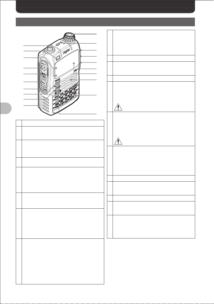
Names and Functions of Controls
a
b
c
d
e
f
g
h
i
j
Before Reading This Manual
Antenna terminal (SMA)*
a
Flashlight (White LED)
b
• This LED can be used as a small flashlight in a
dark place.
A-band BUSY/TX lamp
c
B-band BUSY/TX lamp
These lamps glow green during reception, and
glow red during transmission.
pPTT switch
d
• Press and hold the
Tswitch
e
• Press and hold the
squelch function.
• While pressing the
the
O knob to adjust the squelch level.
v switch
f
While pressing the v key, turn the O knob to
adjust the volume level.
P switch
g
• Press and hold the
turn on the FT-D1.
• Press and hold the
again to turn off the FT-D1.
• Press the
Akey (switching between operating bands)
h
• Pressing the
A-band and B-band.
• Press and hold the
change the Dual Band Reception mode to the
Mono Band Reception mode.
• While operating the FT-D1 in the Mono Band
Reception mode, press the
press the
display.
p switch during transmission.
T switch to deactivate the
F key and T switch, turn
P switch over 1 second to
P switch over 1 second
P switch briefly to lock keys.
A key briefly toggles between
A key over 1 second to
F key and then
A key briefly to enlarge the
k
l
m
n
o
p
q
r
s
t
• Pressing the
modes (frequency APRS and GPS).
• Press the hold the
the Set mode.
Battery pack*
j
O knob
k
Turn this knob to change frequencies or select a
memory channel.
GPS antenna
l
MIC/SP jack*
m
Connect a speaker microphone or earpiece
microphone to this jack.
It is not waterproofed when an external
microphone is connected.
EXT DC IN jack*
n
• Connect an external power supply adapter with
a cigarette lighter plug (E-DC-5B) or an external
power cable (E-DC-6) to this jack.
• When charging the battery pack, connect the
battery charger (PA-48) to this jack.
DATA terminal*
o
• Use this terminal when using a clone function or
updating the firmware.
• Connect the optional camera-equipped
microphone (MH-85A11U).
• For how to update the firmware, access our
home page.
Microphone
p
Display
q
This LCD displays reception frequencies and
various settings.
Speaker
r
15 keys
s
These keys are used to specify reception/
transmission frequencies and select functions.
F switch
t
• Press the
keys.
• Press and hold the
write a frequency in the memory.
M key switches among display
M key over 1 second to call
Do not connect any product which is not
specified by us. A failure can result.
Do not connect any product which is not
specified by us. A failure can result.
F key briefly to activate function
F key over 1 second to
M key
i
* When the included antenna and battery pack are
installed and the MIC/SP jack, EXT DC IN jack,
DATA terminal, and micro SD slot are securely
covered with rubber caps, the FT-D1 can deliver
the waterproofing performance conforming to
IPX5 (See page 10).
12

Names and Functions of Controls
FCCID:K6620445X20
IC:511B-20445X20
YAESUMUSENCO.,LTD.
Key
%
X
D
1
2
3
4
5
6
7
8
9
0
When pressed briefly
When entering a
frequency or calling a
memory CH
Switches between
radio wave types.
Turns on/off the
WiRES-X function.
Turns on/off the
GSM function.
Number “1” Number “1”
Number “2” Number “2” or letter
Number “3” Number “3” or letter
Number “4” Number “4” or letter
Number “5” Number “5” or letter
Number “6” Number “6” or letter
Number “7” Number “7” or letter
Number “8” Number “8” or letter
Number “9” Number “9” or letter
Number “0” Number “0”
When inputting a tag
Moves the cursor to
the left.
———
—
“A”, “B”, “C”, “a”, “b”,
or “c”
“D”, “E”, or “F”, “d”,
“e”, or “f”
“G”, “H”, or “I” , “g”,
“h”, or “i”
“J”, “K”, or “L”, “j”, “k”,
or “l”
“M”, “N”, or “O”, “m”,
“n”, or “o”
“P”, “Q”, “R”, or “S”,
“p”, “q”, “r”, or “s”
“T”, “U”, or “V”, “t”,
“u”, or “v”
“W”, “X”, “Y”, or “Z”,
“w”, “x”, “y”, or “z”
When a key is
When pressed and held
over 1 second
Selects SD card data. Sends the selected
Manipulates member
data.
—
—
—
—
—
—
—
—
—
—
pressed after
the F switch is
pressed
SD card data.
—
Switches between
transmission power
levels.
Selects the spectrum
cope function.
Selects the special
bank function.
Selects the home
channel.
Selects a reversal
function.
Selects the AF DUAL
function.
Displays a station
list.
Displays a digital list.
Selects a beacon
text.
Receives the AM/FM
radio band.
Before Reading This Manual
B
Increases the
frequency.
Switches between
the VFO mode and
V
Memory mode.
Moves the cursor to
the right.
Switches between
letter types. —
Selects the scan
function.
Decreases the
frequency.
Selects the dual
watch function.
13
Names and Functions of Controls
䰢䰒䰛
䰚䰒䰙
䰚䰒䰙
䰔 䰕
䯴䰀䯵
䰢䰒䰛
䰀䯿䯿䯺䯼䯼䯼
䯽䰀䰁䯺䯼䯼䯼
䯴䰃䯵
FCCID:K6620445X20
IC:511B-20445X20
YAESUMUSENCO.,LTD.
a
bcd e f g
A-band
display area
B-band
display area
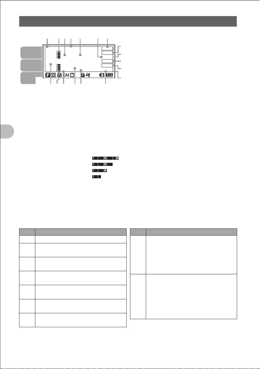
Icon
display
area
Displays choice of the VFO mode or MR
a
(memory) mode.
Displays a sound volume bar graph.
b
Displays a transmission power level icon.
c
Displays an operating frequency.
d
S meter: Displays the radio wave strength in
e
Before Reading This Manual
PO meter: Displays the transmission power
H I: High power (5 W)
L 3: LOW 3 power (2.5 W)
L 2: LOW 2 power (1 W)
L 1: LOW 1 power (0.05 W)
Displays the operating mode (radio wave
f
type).
䰔䰕
䰔䰕䰔 䰕
abc de f
9 steps.
level in 4 steps.
Displays a squelch type (See page 136).
g
TN: Stays lit when the tone encoder
h
i
g
h
i
function is active.
TSQ: Stays lit when the tone squelch
function is active.
DCS: Stays lit when the DCS function is
active.
RTN: Stays lit when the reverse tone
function is active.
PAG: Stays lit when the pager is active.
MSG: Stays on when the message function
is active.
Displays the APRS baud rate (See page 71).
Displays a shift direction during repeater
h
operation. (See page 30)
-Minus shift
+Plus shift
@Split operation
b is displayed when the bell alarm function
is active (See page 140).
i
Displayed when the vibrator function is
active.
Solid line ():
BUSY vibrator function (See page 139)
Dashed line:
SIGNALING vibrator function (See page
139)
Short dashed line (----):
APRS MSG vibrator function (See page 96)
Icons
Icon Description
Lights when a function key is pressed.
f
Stays lit during internet communication
i
such as WiRES (See page 31).
Stays lit when the DTMF function is
d
active (See page 36, 130).
Stays lit when the APO function is
[
active (See page 150).
Stays lit when the LOCK function is
l
active (See page 29).
Stays lit when the MUTE function is
]
active (See page 27).
Stays lit when a micro SD memory card
s
is inserted.
14
Icon Description
Displays the transmission power level
(See page 27).
H I: High power (5W)
H I
L 3: LOW 3 power (2.5W)
L 2: LOW 2 power (1W)
L 1: LOW 1 power (0.05W)
Displays the battery charge level.
< : Enough battery power
> : Low battery power
? : Poor battery power.
<
_ : Charge battery.
_ : Charge battery immediately
(blink).
Basic OperationBasic Operation
FCCID:K6620445X20
IC:511B-20445X20
YAESUMUSENCO.,LTD.
Preparation
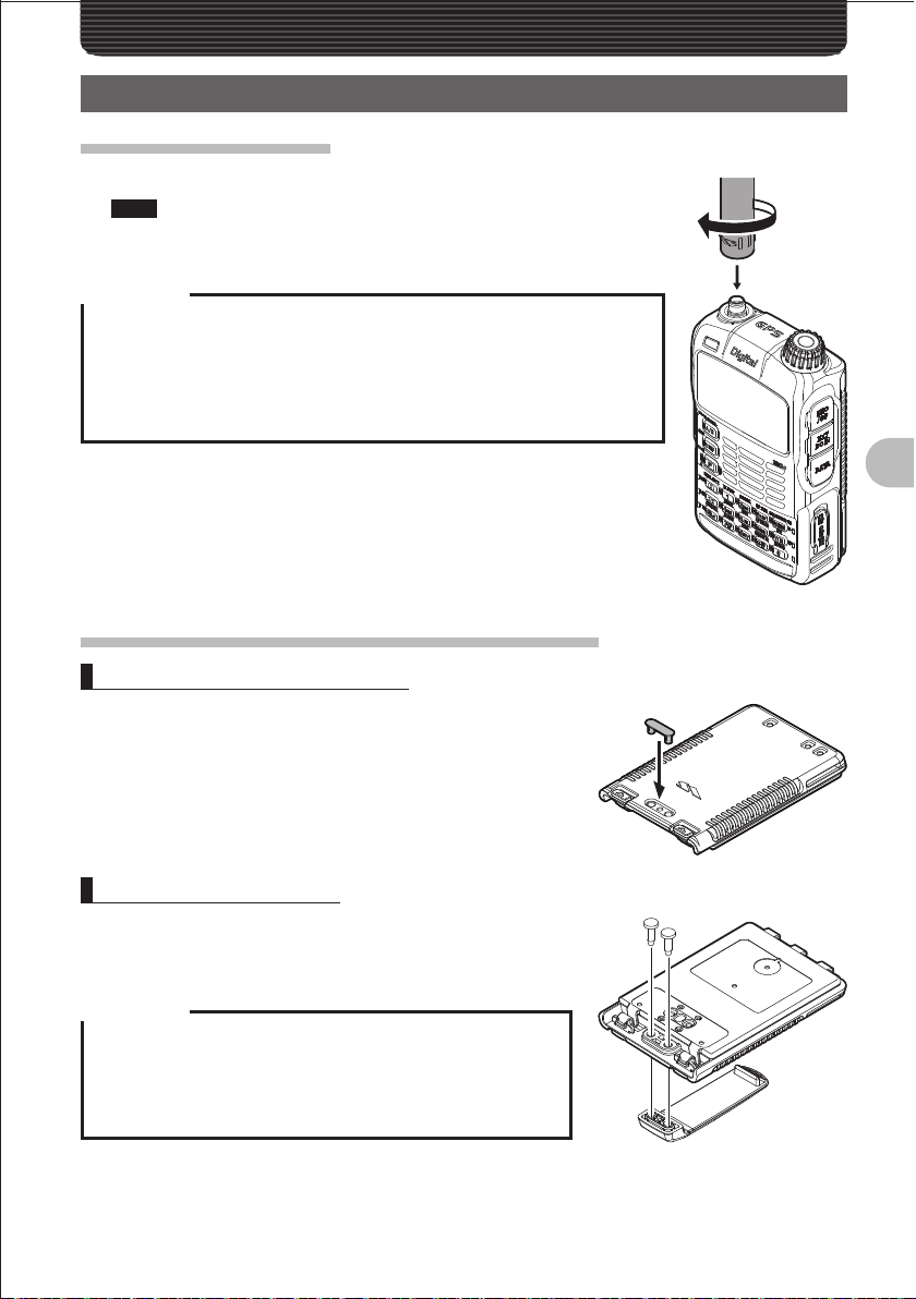
Installing the Antenna
1 Align the antenna with the antenna terminal on the main unit.
Note Be sure to hold the thick root of the antenna when installing it.
2 Turn the antenna clockwise until it is secured.
Precaution
z Do not hold the upper part of the antenna when installing or removing it.
Breaking of wire can occur inside the antenna.
z Do not transmit without installing the antenna. The transmitter circuit can
be damaged.
z When using an detachable antenna other than the supplied one or any
other external antenna, ensure that its SWR is adjusted to 1.5 or lower.
Attaching the Supplied Belt Clip/Protective Cap
Attaching the Protective Cap
1 Attaching the Protective Cap
If you do not use the belt clip, attach the protective cap
to the belt clip attaching opening.
Basic Operation
Installing the Belt Clip
1 Turn over the battery pack.
2 Install the belt clip using the supplied screws (two).
Precaution
z Be sure to use the supplied screws when installing the belt
clip. Using any other screws can result in injury, damage to
parts, and other troubles.
z Be sure to install the protective cap when the belt clip is not
used.
15
Preparation
FCCID:K6620445X20
IC:511B-20445X20
YAESUMUSENCO.,LTD.
Attaching a Hand Strap
If you attach a hand strap to the FT1DR, its string which is inserted in and secured to
the strap hole in the transceiver must have a diameter of 1 mm.
* The hand strap does not come with the FT1DR.
1 Remove the battery pack.
2 Attach the hand strap.
Precaution
Use a hand strap which can stand the weight of the FT1DR.
If you use a hand strap which is not strong enough, the hand strap can
break and the FT1DR can fall down, resulting in injury, damage to parts,
and other troubles.
Basic Operation
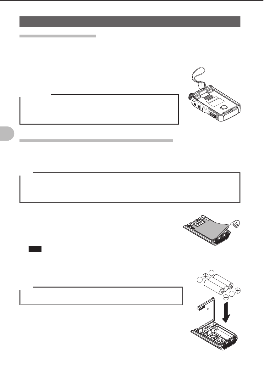
How to Use the Battery Case (FBA-39) (Option)
The optional battery case (FBA-39) allows three AA Alkaline batteries to be used as a
power supply.
Hint
When the battery case (FBA-39) is used, you can select a power output level from:
Low Power (L1): 0.05 W
Low Power (L2): 1W
Note that Low Power (L3) and High Power are not available.
1 Open the cover.
Lift up the lower right corner indicated by the hand pointer in
the illustration.
2 Put alkaline batteries in the battery case.
Note Use three alkaline batteries. Pay attention to polarities (+ and )
of the alkaline batteries.
3 Close the cover.
Push hard four corners of the cover to close it tightly.
Hint
When the batteries become weak, _ is displayed on the LCD. When
the batteries become far weaker, _ blinks on the LCD.
16
Preparation
FCCID:K6620445X20
IC:511B-20445X20
YAESUMUSENCO.,LTD.
Precaution
z Manganese batteries cannot be used. Rechargeable AA batteries cannot be used, either.
z Do not use new batteries along with old batteries. The life of new batteries can decrease.
z If you do not use the FT1DR for a long period, remove the batteries from the battery case.
z If the terminal or electrode of the battery case is dirty, the FT1DR can malfunction due to poor
contact, resulting in overheating or explosion. If the terminal or electrode gets dirty, clean it using a
dry cloth or cotton swab.
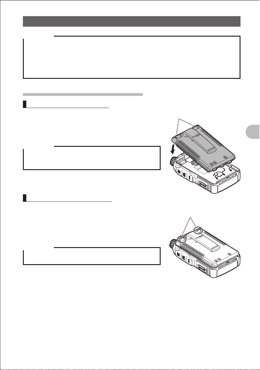
Installing/Removing the Battery Pack
Installing the Battery Pack
1 Insert the bottom tabs of the battery in the slots at
the bottom of the FT1DR.
Lock knobs
2 Push in the lock knobs until they click.
Precaution
When you use the FT1DR for the first time after purchase or
you have not used it for a long period, charge the battery pack
before use.
Removing the Battery Pack
1 While pushing down the lock knobs, remove the
battery pack.
Push down the lock knobs in the direction of the arrow
shown in the illustration.
Push down the lock knobs
in the direction of the arrow.
Basic Operation
Precaution
When releasing the lock knobs, be careful not to hurt your
fingers and nails.
17
Preparation
FCCID:K6620445X20
IC:511B-20445X20
YAESUMUSENCO.,LTD.
Charging the Battery Pack
Precaution
z The battery pack is rechargeable about 300 times. However, improper use such as overcharge or
over-discharge can shorten its life.
z The battery pack is a consumable item. Recharging the battery pack repeatedly will gradually
shorten the time until its power becomes low.
z If the FT1DR is not used for a long period with the battery pack installed, deterioration of the battery
pack can accelerate.
z If you do not use the FT1DR for a long period, be sure to store it with the battery pack removed.
Even if you do not use the FT1DR for a long period, install the battery pack biannually and recharge
the battery pack about 50%.
z Storing the battery pack in a high-temperature place can deteriorate it faster than usual.
Store the battery pack in a place where the ambient temperature is 20°C to +50°C.
z Do not drop or give a strong shock to the battery pack. It can break.
Hints
Basic Operation
• The battery pack contains lithium-ion batteries that can be recharged for repetitive use.
• The FT1DR can be used with either of the following battery packs:
(1) Accessory: FNB-101L (I 7.4 V, 1100 mAh)
(2) Option: FNB-102L (I 7.4 V, 1800 mAh)
• When the battery pack is recharged, its output voltage (about 8 V) becomes higher than the
specified value (7.4 V). This is not a failure.
18
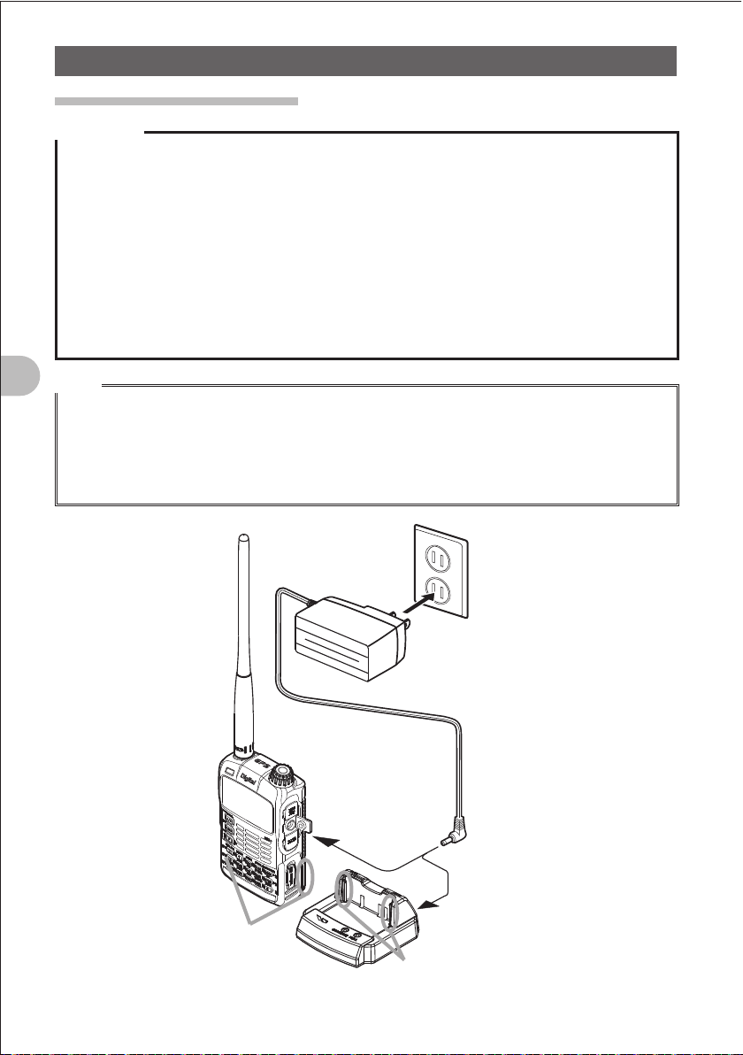
100 - 120 VAC
Battery charger
PA-48
(accessory)
Grooves in
battery pack
Rails
Quick-charge cradle CD-41
(option)
Preparation
FCCID:K6620445X20
IC:511B-20445X20
YAESUMUSENCO.,LTD.
1 Install the battery pack.
2 Turn off the FT1DR.
3 Insert the plug of the battery charger (PA-48A) in the
EXT DC IN jack of the FT1DR.
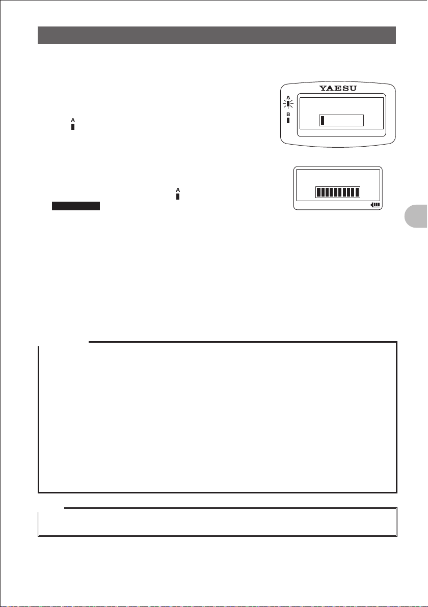
Charging starts.
CHARGING
The lamp glows red and “CHARGING” is displayed
on the LCD.
The charge level is indicated by a bar graph.
It takes about 5 hours to charge the battery pack fully.
When charging is completed, “COMPLETE” is
COMPLETED
displayed on the LCD and the lamp glows green.
Supplement • It takes about 8 hours to charge the FNB-102LI
•
Place the FT1DR on the cradle with the rails of the cradle fit in the grooves in the
When charging the battery pack using the cradle, the LED on the cradle indicate the
(option).
The optional quick-charge cradle (CD-41) requires about 2.5 hours to charge the
supplied battery pack (about 4 hours to charge the optional battery pack FNB-102LI).
battery pack.
state of charging.
During charging: Red glow Fast blink Slow blink
Completion of charging: Green glow
4 Remove the plug of the battery charger from the jack of the FT1DR.
Basic Operation
Precaution
z Neither transmission nor reception can be performed while charging the battery pack using the
supplied battery charger.
z During charging, noise may be generated in the nearby TV or radio.
Charge the battery pack with the battery charger away from the TV or radio as far as possible.
z If “BATTERY NOT INSTALLED” is displayed on the LCD and the battery pack cannot be charged
after lapse of 11 or more hours, stop charging the battery pack immediately.
If the same message is displayed again, the battery pack is presumably at the end of its life or
defective.
If so, replace the battery pack with a new one.
z While charging the battery pack, protect the FT1DR from splash of water.
z Charge the battery pack in a place where the ambient temperature is +5C to +35C.
z If the terminal or electrode of the battery case is dirty, the FT1DR can malfunction due to poor
contact, resulting in overheating or explosion. If the terminal or electrode gets dirty, clean it using a
dry cloth or cotton swab.
Hints
• The battery charger may become hot during charging. This is not a failure.
• If _ flashes, the battery pack charge is depleted. Charge it immediately.
19
Preparation
FCCID:K6620445X20
IC:511B-20445X20
YAESUMUSENCO.,LTD.
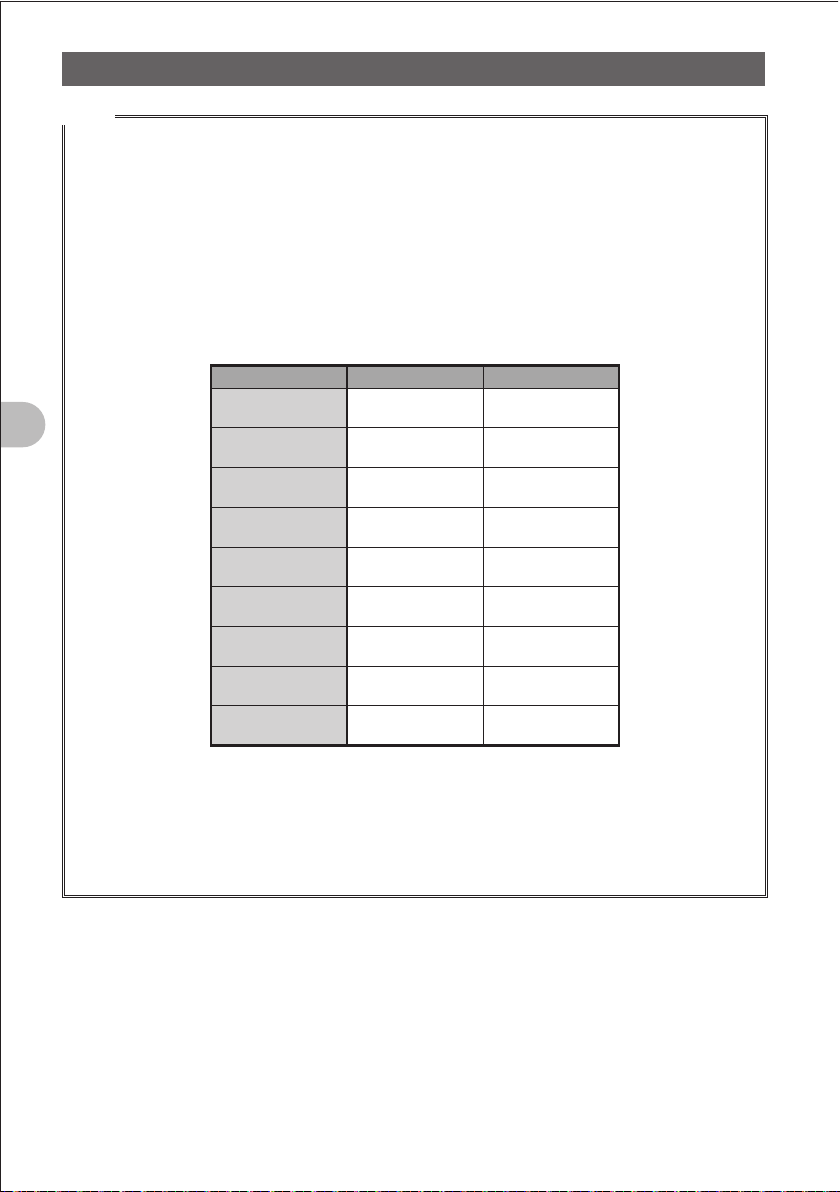
Approximate Operating Hours and Remaining Charge Level Indication
Approximate hours during which the fully charged battery pack or three new AA alkaline
batteries can operate the FT1DR are as follows:
Band
Amateur radio
band
144 MHz
band
430 MHz
band
Battery
pack
FNB-101LI
Approx. 5.0
hours
Approx. 5.0
hours
Battery
pack
FNB-102LI
Approx. 8.5
hours
Approx.8.0
hours
Batter case
FBA-39
Approx. 17
hours
Approx.16
hours
Icon
< : Full battery power
> : Enough battery power
? : Low battery power
_ : Poor battery power
Charge battery.
_ : Charge battery
immediately.
(Blink)
Remarks Approximate hours are estimated assuming that the FT1DR is operated under the
Basic Operation
•
• With an amateur radio band selected, a sequence in which high-power transmission
following conditions. Hours during which the FT1DR can be used actually vary depending
on use conditions, ambient temperature, etc.
The GPS function is deactivated.
is performed for 6 seconds, reception is performed for 6 seconds, and the standby
operation is performed for 48 seconds is repeated.
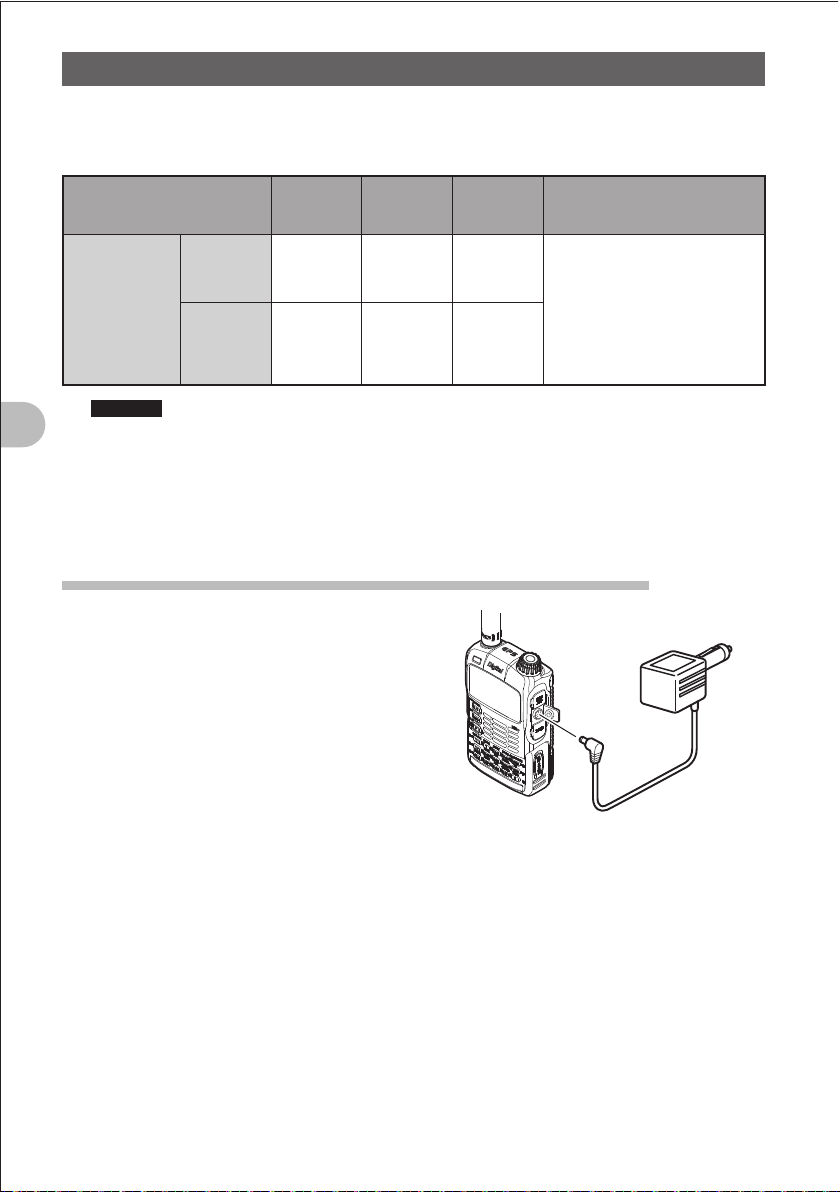
Connecting an External Power Supply for Use in Vehicle
The optional external power supply adapter with
a cigarette lighter plug (E-DC-5B) allows the
FT1DR to be used in a vehicle.
1 Turn off the FT1DR.
2 Insert the plug of the external power supply
adapter with a cigarette lighter plug (E-DC5B) in the EXT DC IN jack of the FT1DR.
3 Insert the cigarette lighter plug of the external
power supply adapter with a cigarette lighter
plug (E-DC-5B) in the cigarette lighter socket
of the vehicle.
To cigarette lighter socket
of vehicle
EXT DC IN jack
External power supply
adapter with
a cigarette lighter plug
E-DC-5B (option)
20
Preparation
FCCID:K6620445X20
IC:511B-20445X20
YAESUMUSENCO.,LTD.
Precaution
z The E-DC-5B is compatible with a 12 VDC cigarette lighter socket.
Do not connect the E-DC-5B to the 24 VDC cigarette lighter socket.
z Use the FT1DR at the minimum required transmission power level to prevent overheating.
z Do not perform continuous transmission for a prolonged period. The FT1DR can overheat, resulting
in a failure or burn.
z If you operate the FT1DR for 7 hours or longer, it is recommended that you remove the battery pack
and install the optional battery case (FBA-39).
z Recharging the fully-charged battery pack repeatedly can shorten its life. Be extremely careful not to
do so when you operate the FT1DR using an external power supply.
z While charging the battery pack, protect the FT1DR from splash of water.
z Charge the battery pack in a place where the ambient temperature is +5C to +35C.
z If the terminal or electrode of the battery case is dirty, the FT1DR can malfunction due to poor
contact, resulting in overheating or rupture. If the terminal or electrode gets dirty, clean it using a dry
cloth or cotton swab.
Hints
• The external power supply requires about 5 hours to charge the battery pack (about 8 hours
to charge the optional battery pack FNB-102LI). If the battery pack is charged with the FT1DR
powered, the charging time increases slightly.
• When the battery pack has been charged fully, charging stops automatically.
• The external power supply can be used with the battery case installed.
• If you connect the FT1DR to the extern al power supply with it turned off, “CONNECTED TO
EXTERNAL POWER” is displayed on the LCD, and about 20 seconds later “BATTERY NOT
INSTALLED” is displayed.
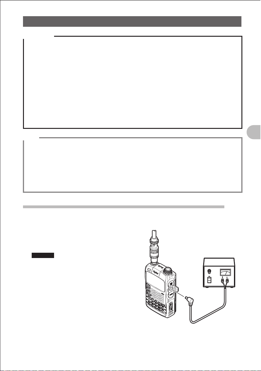
Connecting to an External Power Supply Using a Power Cable
The optional power cable (E-DC-6) allows the FT1DR to be connected to an external
power supply.
1 Turn off the FT1DR.
2 Connect the optional external power supply
cable (E-DC-6) to an external power supply.
Remarks • Connect the red/black wire or white/
• Set the voltage of the external power
black wire to the positive (+) terminal of
the external power supply
the black wire to the negative ()
terminal.
supply to 12-14 V.
, and connect
Connect the
external antenna.
External power supply
3 Insert the plug of the external power supply
in the EXT DC IN jack of the FT1DR.
External power
supply cable
E-DC-6 (option)
Basic Operation
21

Preparation
FCCID:K6620445X20
IC:511B-20445X20
YAESUMUSENCO.,LTD.
Precautions
z When you use the FT1DR with the external power supply cable (E-DC-6) connected to an external
power supply, pay attention to the following:
• The power supply voltage must be 12 V to 14 V.
If the voltage exceeds 14 V, the high voltage protection function is activated to disable high-power
transmission. L3 (2.5 W) is selected automatically to reduce the transmission power.
If the voltage exceeds 16 V, failures such as damage to the electric circuits of the FT1DR can
result. Take extra care.
• Connect the red/black wire or white/black wire of the external power supply cable (E-DC-6) to the
positive (+) terminal of the external power supply, and connect the black wire to the negative ()
terminal.
• Use an external power supply having sufficient current capacity (3 A or more).
• If the supplied antenna remains installed, the external power supply can malfunction, resulting in a
failure. If you use an external power supply, remove the supplied antenna and connect an external
antenna. Place the external power supply sufficiently away from the FT1DR.
z Use the FT1DR at the minimum required transmission power level to prevent overheating.
Basic Operation
z Do not continue transmission for a prolonged period. The FT1DR can overheat, resulting in a failure
or burn.
z If you operate the FT1DR for 7 hours or longer, it is recommended that you remove the battery pack
and install the optional battery case (FBA-39).
z Recharging the fully-charged battery pack repeatedly can shorten its life. Be extremely careful not to
do so when you operate the FT1DR using an external power supply.
z While charging the battery pack, protect the FT1DR from splash of water.
z Charge the battery pack in a place where the ambient temperature is +5C to +35C.
z If the terminal or electrode of the battery case is dirty, the FT1DR can malfunction due to poor
contact, resulting in overheating or explosion. If the terminal or electrode gets dirty, clean it using a
dry cloth or cotton swab.
Hints
• The external power supply requires about 5 hours to charge the battery pack (about 8 hours
to charge the optional battery pack FNB-102LI). If the battery pack is charged with the FT1DR
powered, the charging time increases slightly.
• The external power supply can be used with the battery case installed.
In this case, “BATTERY NOT INSTALLED” is displayed on the LCD of the FT1DR; however, the
FT1DR can be used, without any problem, with the battery case installed.
• If you connect the FT1DR to the external power supply with it turned off, “CONNECTED TO
EXTERNAL POWER” is displayed on the LCD, and about 20 seconds later “BATTERY NOT
INSTALLED” is displayed.
22
Communication
FCCID:K6620445X20
IC:511B-20445X20
YAESUMUSENCO.,LTD.
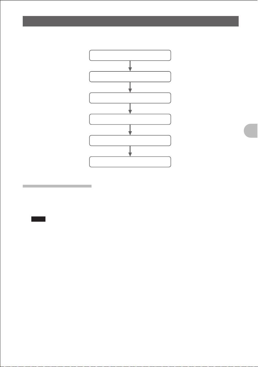
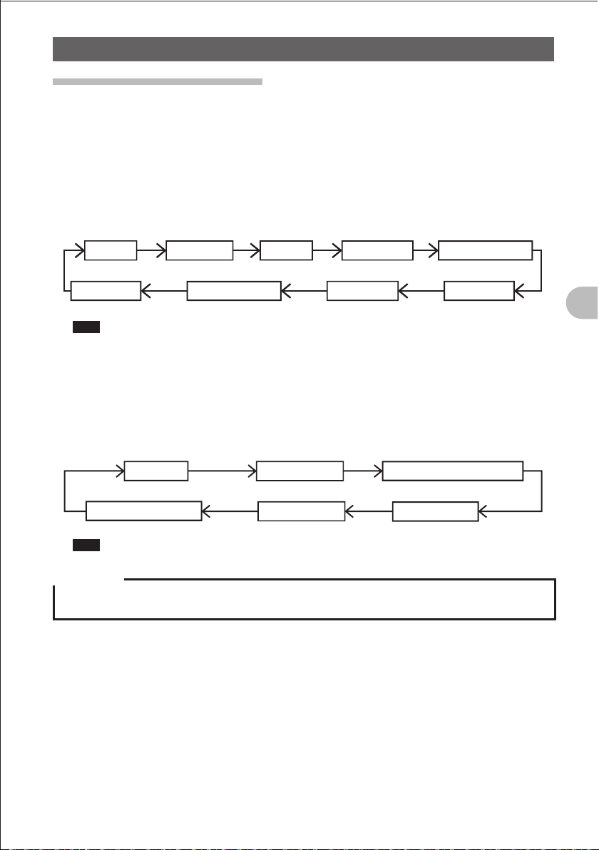
Let’s try communication using the FT1DR in the analog communication mode.
Follow the procedure below.
Turn the power on.
Adjust the volume level.
Select an operating band.
Select a frequency (band).
Tune in to a frequency.
Start communication.
Turning on the Power
1
Press and hold the P switch over 1 second.
An opening message is displayed, and then two frequencies (A-band frequency and
B-band frequency) are displayed at the same time.
Hints You can change the information such as the power supply voltage and the opening message
displayed at power-on. Press and hold the M key over 1 second to select the Set mode, and
then select “1 DISPLAY” “7 OPENING MESSAGE”.
In addition, you can cause the FT1DR to display the reception frequency immediately without
displaying the opening message (See page 154).
O Turning off the Power
To turn off the power, press and hold the P switch over 1 second.
Basic Operation
23
Communication
FCCID:K6620445X20
IC:511B-20445X20
YAESUMUSENCO.,LTD.
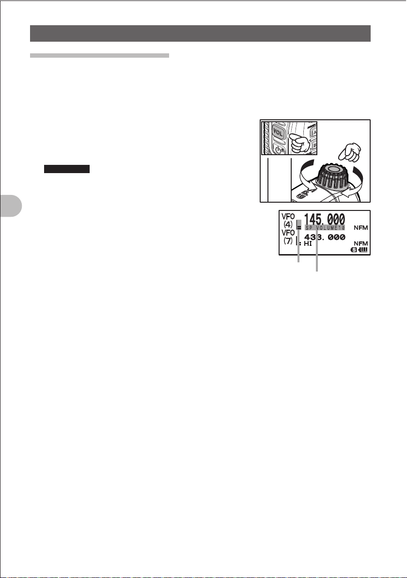
Adjusting the Volume Level
The FT1DR allows the volume level to be adjusted for the A-band and B-band
separately.
1 Press the A key to select a band for which you want to adjust the volume level.
Pressing the A key toggles between the A-band and B-band.
2 While pressing the v key, turn the O knob to
adjust the volume level.
The volume bar graph moves up/down while
blinking.
Supplement If no sound is heard from the speaker, press the
T key and then adjust the volume level while
listening to white noise.
3 Release the v key.
The Volume Level Adjustment mode is canceled.
Basic Operation
Volume bar graph blinks.
One of SP VOLUME 0 to
SP VOLUME 32 is displayed.
24
Communication
FCCID:K6620445X20
IC:511B-20445X20
YAESUMUSENCO.,LTD.
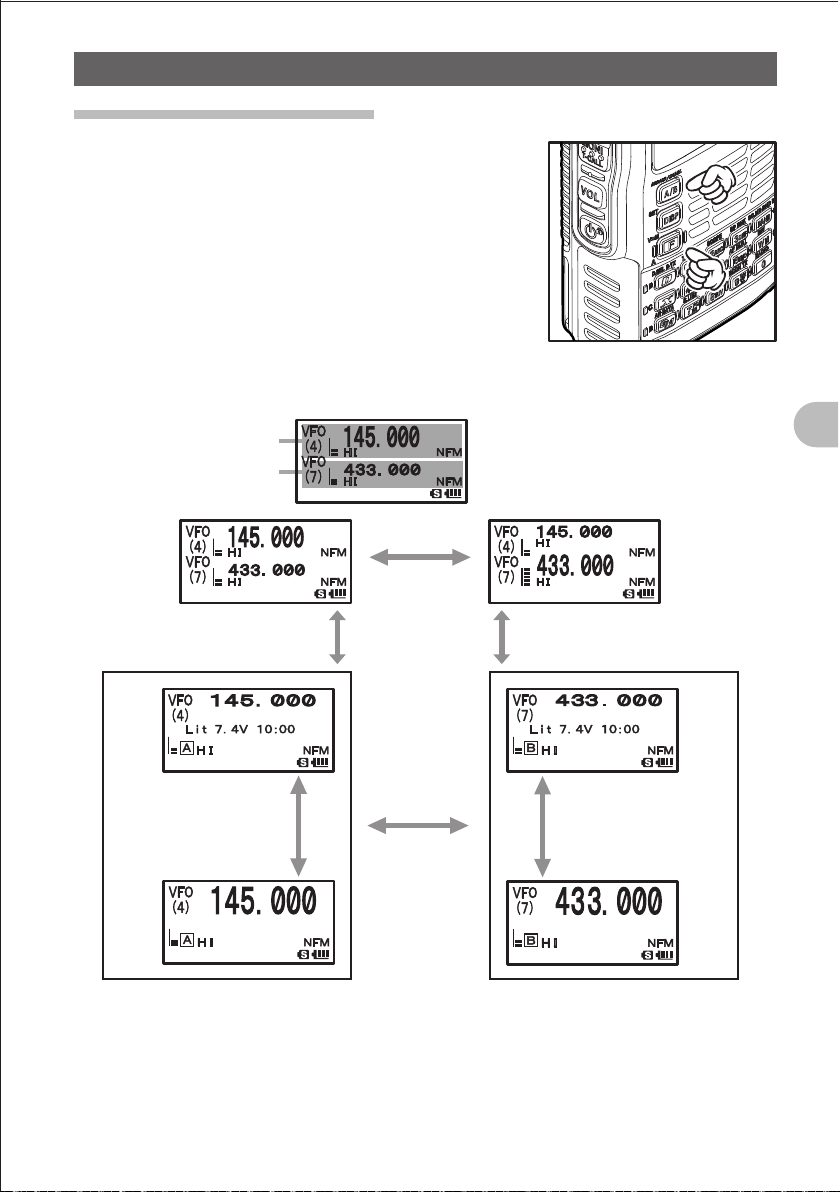
Selecting an Operating Band
The frequency displayed on the LCD in large letters is
called an operating band.
Each operating band allows you change the frequency
and perform transmission.
Pressing the A key briefly toggles between the information for A-band and the
information for B-band.
A-band (operating band)
B-band
Press and hold the A key
for about 1 second.
Press the F key
briefly.
Press the A key
briefly.
Press the
A key
briefly.
Press the
A key
briefly.
Basic Operation
Press and hold the A key
for about 1 second.
Press the F key
briefly.
Press the A key
briefly.
25
Communication
FCCID:K6620445X20
IC:511B-20445X20
YAESUMUSENCO.,LTD.
Hints
• The A-band allows you to perform communication using the following amateur radio bands.
144 MHz band, 430 MHz band
The A-band also allows you to perform reception using the following radio bands:
AIR band, INFO band (1), INFO band (2)
• The B-band allows you to perform communication using the following amateur radio bands.
144 MHz band, 430 MHz band
The B-band also allows you to perform reception using the following radio bands:
AIR band, INFO band (1)
• The number (1-9) corresponding to the selected frequency band is displayed on the LCD.
For the relationship between the numbers and frequency bands, see the following table:
Reception frequencies of A-band and B-band
Basic Operation
Frequency band No.
(1)
(2)
(3)
(4)
(5)
(6)
(7)
(8)
(9)
A-band B-band
1.8 MHz to 30 MHz
(SW band)
30 MHz to 76 MHz
(50 MHz band)
108 MHz to 137 MHz
(AIR band)
137 MHz to 174 MHz
(144 MHz band)
174 MHz to 222 MHz
222 MHz to 420 MHz
(INFO band (1))
420 MHz to 470 MHz
(430 MHz band)
470 MHz to 770 MHz
770 MHz to 999 MHz
(INFO band (2))
108MHz to 137MHz
(AIR band)
137 MHz to 174 MHz
(144 MHz band)
174 MHz to 222 MHz
222 MHz to 420 MHz
(INFO band (1))
420 MHz to 470 MHz
(430 MHz band)
470 MHz to 770 MHz
• The A-band and B-band can be received at the same time.
You can receive an amateur radio frequency while listening to the AIR band, or receive two amateur
radio frequencies on the same frequency band at the same time (V+V/U+U: Dual frequency
reception on the same band).
• The sub-band operation function allows you to change the sub-band to the operating band during
dual reception (See page 29).
26
Communication
FCCID:K6620445X20
IC:511B-20445X20
YAESUMUSENCO.,LTD.
Selecting a Frequency Band
The FT1DR allows you to select a frequency band for the A-band and a frequency band
for the B-band separately.
O Setting a Frequency Band for the A-band
1 Press the A key.
Select the A-band.
2 Press the B key briefly.
Select a frequency band.
SW band (1)
Hint Pressing the F key briefly and then pressing the B briefly changes frequency bands in
the reverse order.
50 MH䡖㻌band (2)
AIR band (3) 144 MHz band (4)
430 MHz band (7)470 MHz to 770 MHz (8)INFO band (2) (9)
174 MHz to 222 MHz (5)
INFO band (1) (6)
O Selecting a Frequency Band for the B-band
1 Press the A key.
Select the B-band.
2 Press the B key briefly.
Select a frequency band.
AIR band (3) 144 MHz band (4) 174 MHz to 222 MHz band (5)
470 MHz to 770 MHz (8)
Hint Pressing the F key briefly and then pressing the B briefly changes frequency bands in
the reverse order.
Precaution
z Digital communication can be performed only on the A-band.
Digital communication cannot be performed on the B-band.
430 MHz band (7)
INFO band (1) (6)
Basic Operation
27
 Loading...