


SCAN OPERATION
FCC ID: K6620335X40
IC: 511B-20335X40
PROGRAMMABLE MEMORY SCAN (PMS
This feature allows you to scan on the sub-band limits.
1. Store the lower sub-band limits into the memory channel “P1L”.
2. Store the upper sub-band limits into the memory channel “P1U”.
3. Set the “Main” band to memory mode by pressing the [V/M] key on the “F-1” category, if necessary.
4. Recall the memory channel “P1L” or “P1U”.
5. Press the [F] key briefly to change the [SMART FUNCTION] key’s category to “F-
2”.
6. Press the [SCAN] key on the “F-2” category to initiate the scanner within the programmed range.
7. Press the [SCAN] key again to stop the scanner.
8. Press the [V/M] key on the “F-1” category to change the memory mode, then press the
[
V/M] key again to change the VFO mode.
9. Nine pairs of band limit memories, labeled “P1L/P1U” through “P9L/P9U” available.
You therefore can set lower and upper operation limits on a number of bands, if you
like.
Y ou may customize the functions of the Memory Scan via Set Mode items “D03 MEMOR Y
SCAN TYEP” in the “MEMORY” group, “F04 MEMORY SKIP/SELCT”, “F03 SCAN
RESUME”, “F04 SCAN STOP BEEP” in the “SCAN” group, and “G08 RX COVER-
AGE” in the “SYSTEM” group.
PRIORITY CHANNEL SCAN (DUAL WATCH
This feature is a two-channel scanning capability which allows you to operate on a VFO or
Memory channel, while periodically checking a “Priority” memory channel “000” for activity.
)
)
1. Store the frequency which you wish to check periodic into the “Priority” memory channel
“PRM”.
2. Press the [F] key repeatedly until the [SMART FUNCTION] key’s category replaces
to “F-2”.
3. Press the [DW] key on the “F-2” category to initiate the Dual Watch feature.
4. Press the [SCAN] key again to stop the Dual Watch feature.
You may customize the functions of the Dual Watch feature via Set Mode items “F01
DUAL WATCH STOP” and “F03 SCAN RESUME” in the “SCAN” group.
FTM-350R OPERATING MANUAL 17

BLUETOOTH® OPERATION
FCC ID: K6620335X40
IC: 511B-20335X40
When install the optional BU-1 Bluetooth® Unit, the FTM-350R to send/receive voice
®
message with the optional BH-1A or BH-2A Bluetooth
PAIRING
1. Turn the radio and Bluetooth® Headset both off.
2. Turn the radio on while press and holding the key which is located at the left of the
[
POWER] switch to enter the “Special Function” mode.
3. Rotate the left side [DIAL] knob to select the function menu item “9 B-T PAIRING”.
4. Press the left side [DIAL] knob.
5. Press and hold the power switch on the Bluetooth
®
Bluetooth
6. Press the left side [DIAL] knob to initiate the pairing.
7. If the pairing is successful (requires a 20 to 30 seconds), “PAIRING OK !” notation
will appear on the display. The FTM-350R will turn off and back on again.
When the Bluetooth
Bluetooth
8. Set up the various function of the Bluetooth
BLUETOOTH”.
Headset’s indicator blinks red/blue alternately.
®
Headset is correctly recognized by the FTM-350, the
®
Headset’s indicator will blink blue.
Headset via wireless links.
®
Headset for five seconds, until the
®
via Set Mode items “K01
FTM-350R OPERATING MANUAL18

BLUETOOTH® OPERATION
FCC ID: K6620335X40
IC: 511B-20335X40
OPERATION
1. When the Bluetooth® Headset is correctly recognized by the FTM-350R, “ ” icon
will appear on the display of the FTM-350R and the LED indicator of the Bluetooth
Headset will blink blue.
2. Adjust the receiver audio level using the [VOLUME(+)]/[VOLUME
®
the Bluetooth
3. Press the PTT switch on the Bluetooth
Headset.
®
Headset to transmit. Release the PTT switch
to return to receive.
4. If your Bluetooth
®
Headset is BH-2A, you may adjust the microphone gain (Five
steps) of the BH-2A by pressing the [VOLUME(+)]/[VOLUME
ing and holding the PTT switch, if desired.
®
5. The communication range between the Bluetooth
Headset and FTM-350 is around
1 m (3 ft). If you move out of range, a beep will be heard from the Bluetooth
set to alert you. If you move back into range, the Bluetooth
alert you that you are back within range.
®
Headset.
®
Headset is low;
®
Headset.
6. When the battery voltage of the Bluetooth
®
a. the LED on the Bluetooth
Headset will blink Red and Blue.
b. a beep will be heard from the Bluetooth
c. the “
” icon on the FTM-350R will be blinking fast.
Charge the battery of the Bluetooth
In the factory default, the FTM-350R’s internal and external speakers are disabled when
the Bluetooth
®
Headset is correctly recognized. Additionally, the microphones which lo-
cated on the front panel and connected to the front panel MIC jack are also disabled when
®
the Bluetooth
Headset is correctly recognized. However, the microphone which con-
nected to the transceiver’s MIC jack is alive.
You may customize the Bluetooth
®
operation via Set Mode items “K01 BLUETOOTH”
in the “OPTION” group. See page 42.
(–)]
switches on
(–)]
switch while press-
®
Head-
®
Headset will beep to
®
FTM-350R OPERATING MANUAL 19

INTERNET CONNECTION FEATURE
FCC ID: K6620335X40
IC: 511B-20335X40
The FTM-350R can be used to access a “node” (repeater or base station) which is tied into
the Vertex Standard WiRES™ (Wide-Coverage Internet Repeater Enhancement System)
network, operating in the “SRG” (Sister Radio Group) mode. Details may be found at the
WiRES-II Web site: http://www.vxstd.com/en/wiresinfo-en/.
SRG (“SISTER RADIO GROUP”) MODE
1. Sets the Set Mode item “J06 WiRES” in the “SIGNALING” group to “SRG”. See
page 41.
2. Selects the access number corresponding to the WiRES™ repeater via Set Mode item
“J07 WiRES MEMORY” in the “SIGNALING” group. See page 41.
3. When exit from the Set Mode, activate the Internet Connection feature in the “SRG”
mode.
4. With the Internet Connection feature activated, the FTM-350R will generate a brief
(0.1 sec) DTMF tone according to your selection in step 2. This DTMF tone is sent at
the beginning of every transmission to establish or maintain the link to the remote
WIRES™ repeater operating in the “SRG” mode.
4. To disable the Internet Connection feature, select the “ OFF” selection in the Set Mode
item “J06 WiRES”.
FTM-350R OPERATING MANUAL20

INTERNET CONNECTION FEATURE
FCC ID: K6620335X40
IC: 511B-20335X40
FRG (“FRIENDLY RADIO GROUP”) MODE
1. Store the access code of the Internet link to the DTMF memory register via Set Mode
item “J02 DTMF MEMORY” in the “SIGNALING” group. See page 40.
2. Sets the Set Mode item “J06 WiRES” in the “SIGNALING” group to “FRG”. See
page 41.
3. When exit from the Set Mode, activate the Internet Connection feature in the “FRG”
mode.
4. To access the FRG node, perform the following procedures while pressing the PTT
switch:
1) Press the [WiRES] key (located at the left edge of the [SMART FUNCTION] key
while transmitting).
2) Rotate the [DIAL] knob to select the DTMF memory register corresponding to the
WiRES™ repeater you wish to establish an internet link.
3) Press the [WiRES] key again to transmit the access code.
5. T o disable the Internet Connection feature, select the “OFF” selection in the Set Mode
item “J06 WiRES”.
FTM-350R OPERATING MANUAL 21

DTMF OPERATION
FCC ID: K6620335X40
IC: 511B-20335X40
MANUAL DTMF TONE GENERATION
1. Press the microphone’s PTT switch to begin transmission.
2. While transmitting, press the desired numbers key on the microphone.
3. When you have sent all the digits desired, release the PTT switch.
DTMF AUTODIALER
1. Store the telephone number to the DTMF memory register via Set Mode item “J02
DTMF MEMORY” in the “SIGNALING” group. See page 40.
2. Sets the Set Mode item “J03 DTMF MODE” in the “SIGNALING” group to “ON”.
See page 40.
3. When exit from the Set Mode, activate the DTMF Autodialer.
4. To send the telephone number, perform the following procedures while pressing the
PTT switch:
1) Press the [DTMF] key (located at the left side of the [POWER] key while trans-
mitting).
2) Rotate the [DIAL] knob to select the DTMF memory register corresponding to the
telephone number you wish to send.
3) Press the [DTMF] key again to transmit the telephone number.
5. To disable the DTMF Autodialer, select the “OFF” selection in the Set Mode item “J06
DTMF MODE”.
You may send the telephone number by pressing the microphone’s numeric key ([1] through
[9])
corresponding to the DTMF memory string you wish to send.
FTM-350R OPERATING MANUAL22
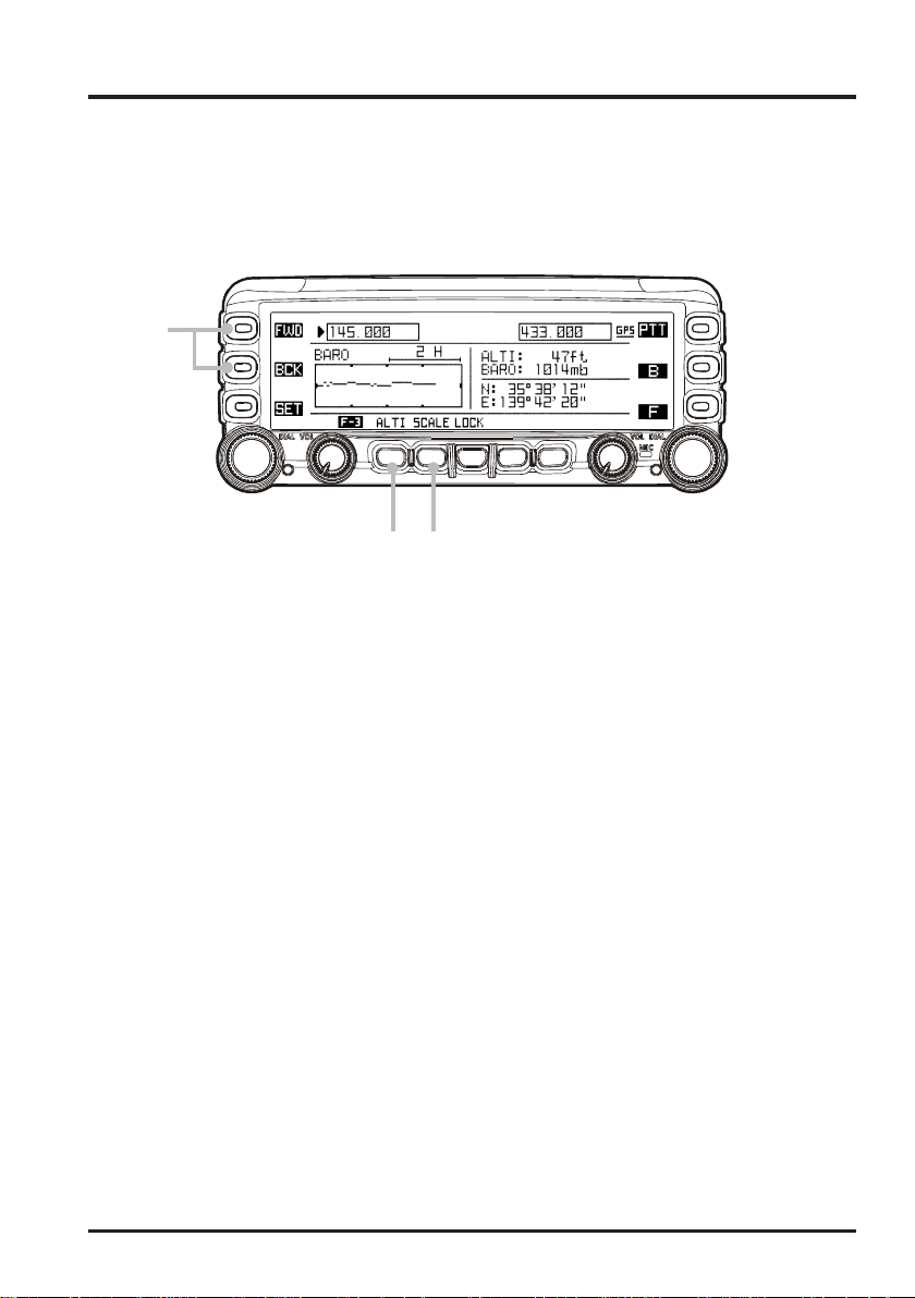
BARO/ALTI PAGE
FCC ID: K6620335X40
IC: 511B-20335X40
The FTM-350R can display the current Barometric Pressure and relative changes in the
pressure. Furthermore, if you install the optional FGPS-1 or FGPS-2
FTM-350R can display the current altitude and relative changes in the altitude.
To display the “Baro/Alti” Page, enablesthe “BARO/ALTI” page via Set Mode item “C01
DISPLAY SELECT” in the “DISPLAY” group, beforehand. See page 33.
1
23
4
Press the [FWD] or [BCK] key repeatedly, until the “Baro/Alti” Page appears.
1
The current Barometric Pressure appears at the upper right of the display , and indicates
the relative changes in the pressure (barometric chart) in the left half of the display.
Additionally, if you install the optional GPS Unit, your current altitude appears at the
upper right of the display, and your current position (Longitude/Latitude) appears at
the lower right of the display.
Press the [SCALE] key to change the time scale of the barometric chart. Available
2
selections are “2H”, “6H”, “12H”, and “24H”.
Press the [ALTI] key to change the “barometric” chart to the “altitude” chart. You may
3
also change the time scale of the altitude chart by pressing the [SCALE] key.
To return to the “barometric” chart, press the [BARO] key.
3
To return to the “Radio” page, press the
Page appears.
[
FWD] or [BCK] key repeatedly, until the “Radio”
GPS Unit, the
You may change the unit of the barometric and altitude via Set Mode item “G10 UNIT
SELECT” in the “SYSTEM” group (see page 37).
: The
FTM-350R OPERATING MANUAL 23
FGPS-2 GPS Unit requires CT-133 GPS Antenna Cable and CT-136 GPS An-
tenna Adapter.
 Loading...