

Page 1
A
DVANCED INTERFERENCE
The FT-2000D includes an unmatched array of RF selectivity-enhancing features. Please study the material below carefully, so as to understand the various features completely.
-S
UPPRESSION
F
EATURES: RF F
RONT END
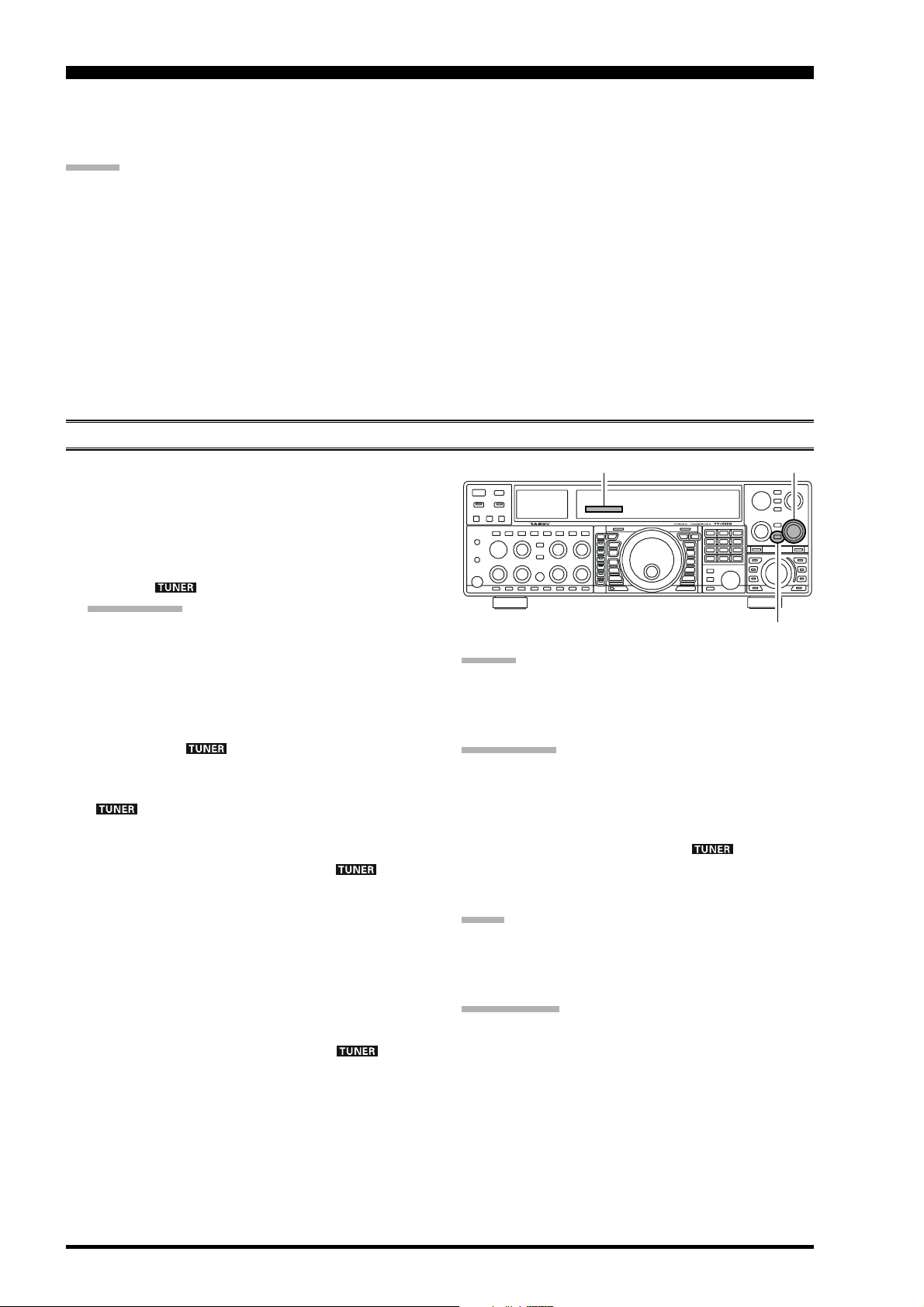
USING THE VRF (VARIABLE RF FRONT-END FILTER
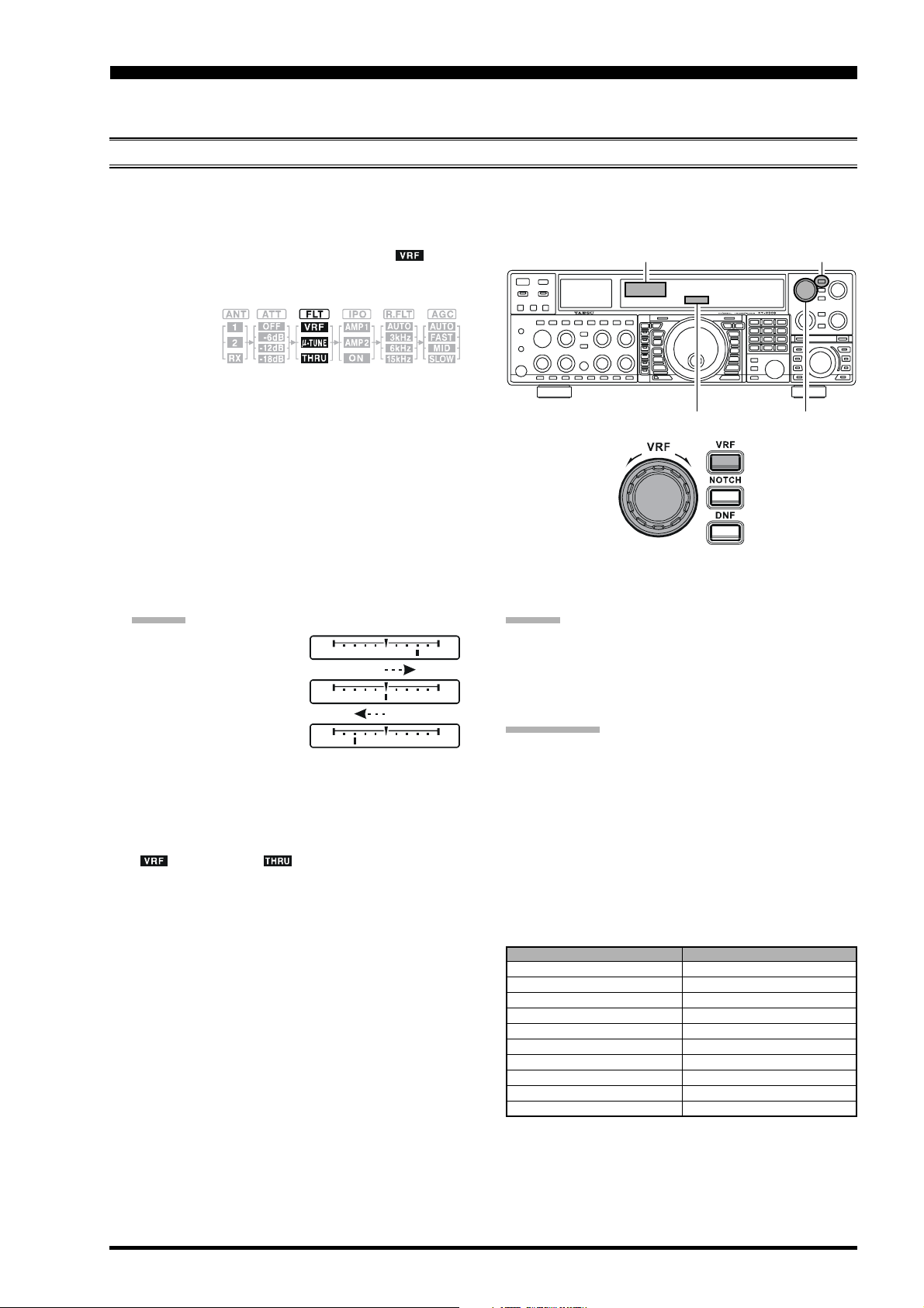
The VRF system is a high-performance RF front-end preselector that has high Q factor and low insertion loss. VRF provides outstanding rejection of out-of-band signals, and can significantly improve reception in tough co-location operations
such as a contest or DX-pedition. The FT-2000D’s VRF system affects the 1.8 - 28 MHz amateur bands only.
1. Press the [VRF] button momentarily. The “ ” icon
will appear at the FLT column of the Receiver Configuration Indicator on the display, and the VRF system will be
engaged,
centered on
your current Amateur band.
2. You may rotate the [VRF] knob to skew the position
of the VRF system relative to your operating frequency.
Because the VRF system is relatively broad, although
still much narrower than the fixed bandpass filter), you
may not hear much difference in the background noise
or signal quality when you make minor adjustments.
However, if you have receiving problems associated
by a very strong signal, rotation of the [VRF] knob
may help reduce the strength of the interfering station,
allowing improved reception of the desired signal if
overload was degrading reception.
ADVICE :
You may observe the
relative skew of the
VRF system in the Tuning Offset Indicator on
the display while turning
the [VRF] knob.
After moving the passband of the VRF system
manually, you may re-center it on the current Amateur band by pressing and holding in the [VRF
button for two seconds.
3. To switch VRF off, press the [VRF] button until the
“ ” icon shows “ ” in the FLT column of the
Receiver Configuration Indicator on the display; this
confirms that the VRF circuit has been removed from
the incoming received signal path.
ADVIC E:
The VRF filter affects both the Main (VFO-A) and Sub
(VFO-B) bands.
The VRF Filter operational status will be memorized
independently on each VFO in the VFO stack.
QUICK POINT:
The VRF filter, utilizing high-quality coils and capacitors
that provide high Q, yields a passband that is approximately
]
20% to 30% the width of a traditional, fixed bandpass filter. As a result, significantly more “unwanted” signal rejection is provided. Within each Amateur band, the following adjustment steps are provided, if you wish to skew
the response in a particular direction so as to enhance interference rejection even more. The actual “sound” of the
signal you are listening to will remain unchanged, however.
AMATEUR BAND
1.8 MHz
3.5 MHz
10 MHz
14 MHz
18 MHz
21 MHz
24.5 MHz
28 MHz
Receiver Configuration Indicator
Offset Tuning Indicator
5 MHz
7 MHz
)
[
VRF] Button
[
VRF] Knob
VRF ADJUSTMENT STEPS
62 steps
62 steps
62 steps
62 steps
30 steps
30 steps
20 steps
20 steps
20 steps
20 steps
Page 53FT-2000D OPERATING MANUAL
Page 2
I
NTERFERENCE
R
EJECTION
(S
IGNALS OFF FREQUENCY BY JUST A FEW KHZ
)
R.FLT (ROOFING FILTERS
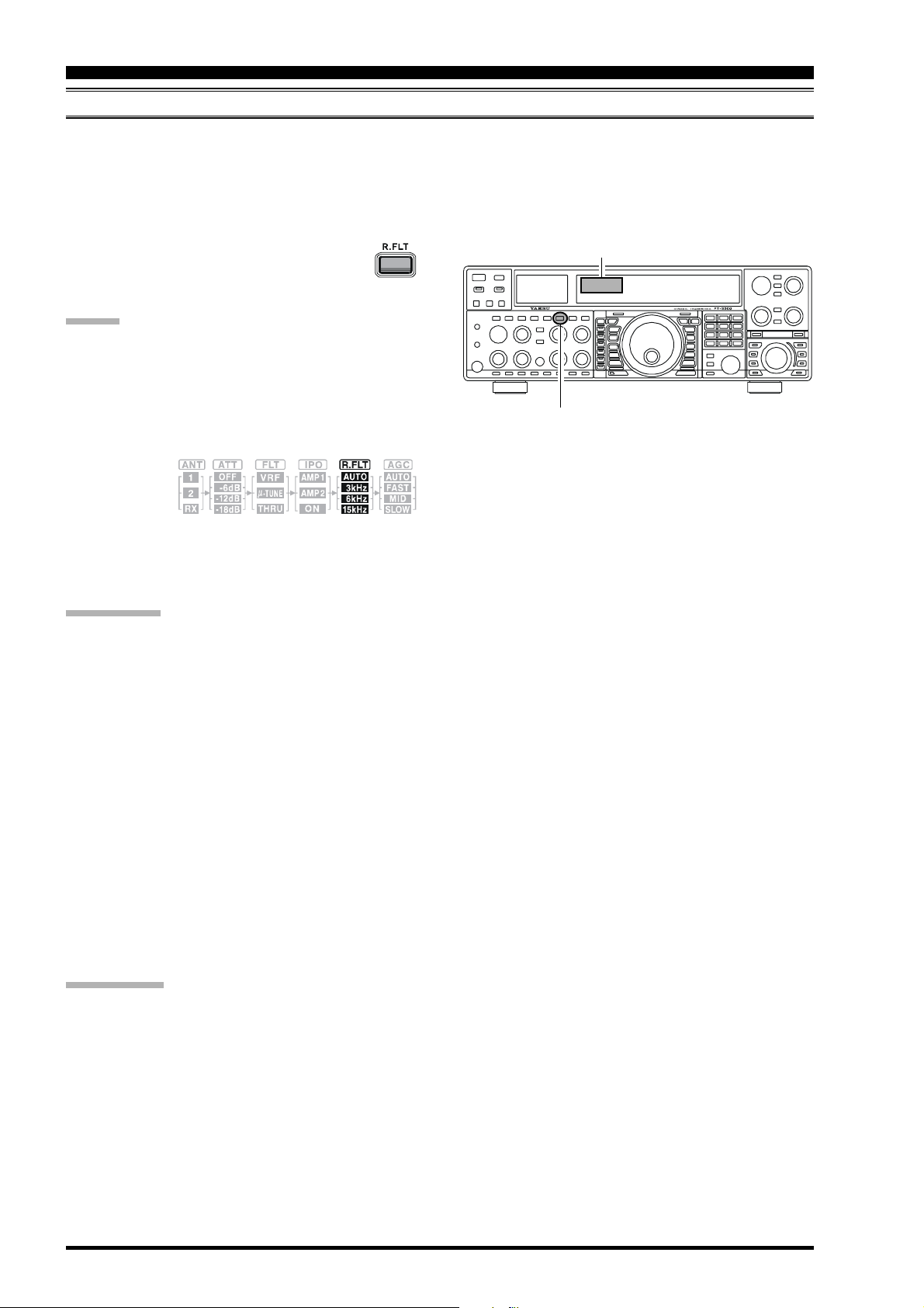
Narrow-band Roofing Filters of 15 kHz, 6 kHz, and 3 kHz bandwidths are provided in the first IF, right after the first mixer.
These filters provide protection fort the 2nd mixer, DSP, and other circuitry that follow and can dramatically improve
reception on a very crowded band (during a contest, etc.). Typically, the AUTO selection mode is satisfactory for most
operating situations, but in an extremely crowded phone band you may wish to select, for example, the 3 kHz roofing filter
for SSB operation.
Press the [R.FLT] button to toggle the Roofing
Filter selection.
AUTO 15 kHz 6 kHz 3 kHz AUTO
ADVICE :
The Roofing filter selection affects the Main band
(VFO-A) only. The Sub band’s (VFO-B) Roofing filter is fixed at a bandwidth of 15 kHz.
As you repeatedly press the [R.FLT] button, you will
observe changes in the notation in the R.FLT column
of the Receiver Configuration Indicator on the display,
denoting the
Roofing Filter currently
in use.
Typically, this selection will be set to “AUTO.”
The Roofing Filter selection will be memorized inde-
pendently on each VFO in the VFO stack.
)
Receiver Configuration Indicator
[
R.FLT] Button
QUICK POINT:
The “AUTO” selection of the Roofing Filter is based
on the operating mode. However, you may override
the automatic selection, if band conditions warrant a
different (usually, a tighter) selection.
The AUTO mode Roofing Filter selections are shown
below:
AM/FM/FM-PKT: 15 kHz
LSB/USB/PKT: 6 kHz
CW/RTTY: 3 kHz
When the Roofing filter mode is set to “AUTO” and
the Noise Blanker is turned On, the Roofing Filter bandwidth will automatically be set to 15 kHz, as this setting provides the most effective noise blanking. However, you still may override the automatic setting, and
select a more narrow Roofing Filter. Noise blanking
may be compromised, however, with a tighter Roofing
Filter in the line.
TERMINOLOGY:
A “Roofing Filter,” as its name implies, places a “Roof”
over the receiver’s IF system bandwidth. This “Roof” protects the circuitry downstream from the first mixer from
interference, just as a roof on a house protects the contents
from rain and snow.
Page 54 FT-2000D OPERATING MANUAL
Page 3
I
NTERFERENCE
R
EJECTION
(S
IGNALS WITHIN
3
KHZ
CONTOUR CONTROL OPERATION
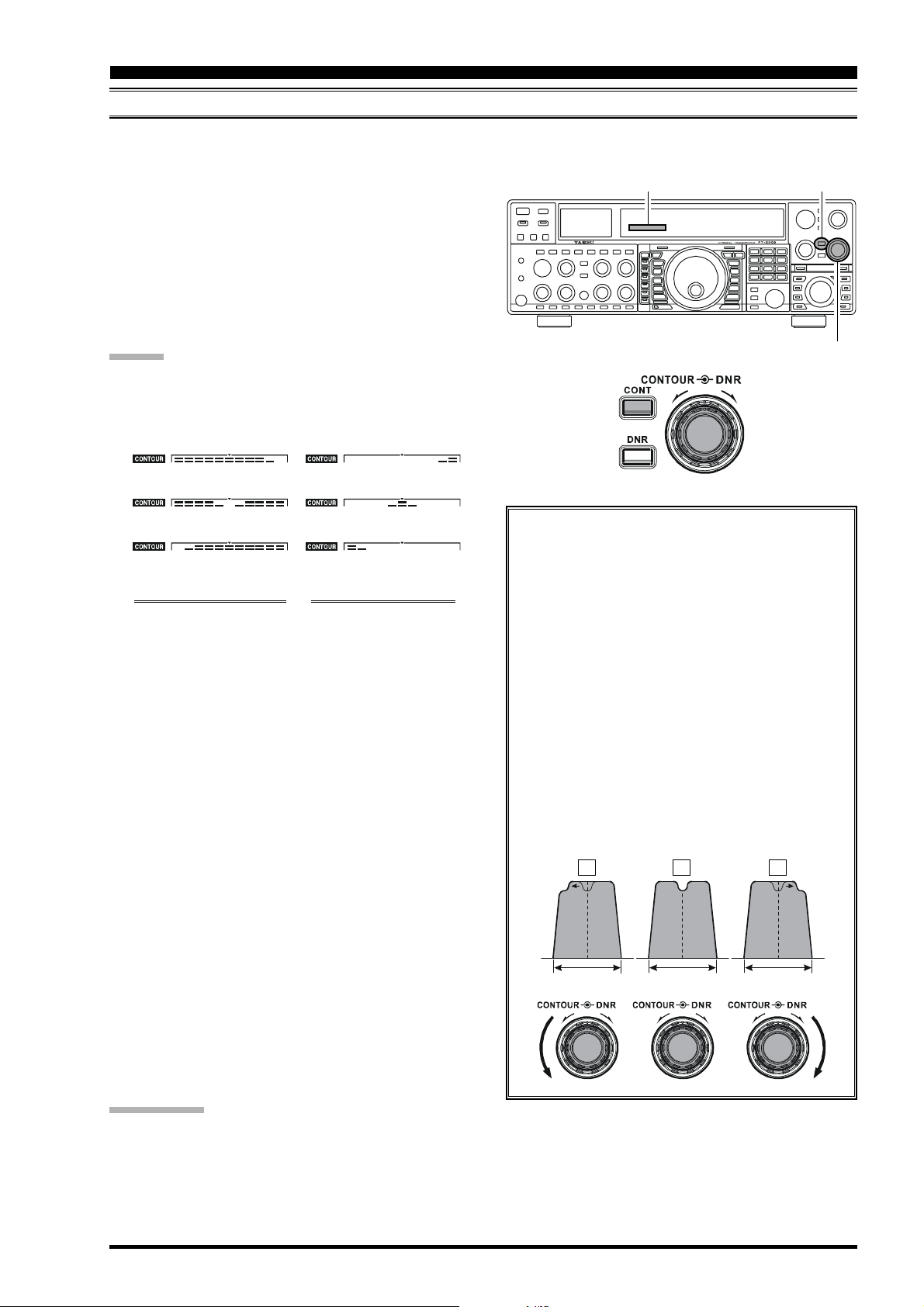
The Contour filtering system provides a gentle perturbation of the IF filter passband, so as to suppress or enhance certain
frequency components, thus enhancing the sound and/or readability of a received signal.
[
1. Press the [CONTOUR] button. The Contour notation
will appear in the display to confirm that the Contour
filter is engaged.
2. Rotate the [CONTOUR] knob to achieve the most
natural-sounding audio reproduction on the incoming
signal.
3. To cancel Contour tuning, press the [CONTOUR] button once more.
ADVICE :
The Contour filter affects the Main band (VFO-A) only.
You may observe the graphically-depicted peak posi-
tion of the CONTOUR Filter in the CONTOUR indicator on the display.
CONTOUR Indicator
CONTOUR] Button
[
CONTOUR] Knob
)
[
CONTOUR] button
Fully Clockwise
[
CONTOUR] button
Center
[
CONTOUR] button
Fully Counter-Clockwise
CONTOUR GAIN “MINUS” CONTOUR GAIN “PLUS”
The Contour filter’s level (either nulling or peaking)
may be adjusted using Menu item “090 rdSP CNTR
LV.” The factory default setting is for a null of “–15”
(dB).
The bandwidth over which the Contour filter effect is
applied may be adjusted using Menu item “091 rdSP
CNTR WI.” The factory default setting is “10.”
When the optional DMU-2000 Data Management Unit
is connected, the Audio Scope (on the “Oscilloscope”
page) is particularly useful when adjusting the Contour control. Not only can you see the effect of the
null/peak of the Contour system, but you also can see
the position of the null/peak with respect to frequency
components of interest on the incoming signal. You
may then observe (on the Audio Scope) the effect of
the Contour control while listening to the effect on the
signal, and this will help build your intuition on how
best to use Contour tuning in the future.
[
CONTOUR] button
Fully Clockwise
[
CONTOUR] button
Center
[
CONTOUR] button
Fully Counter-Clockwise
With reference to Figure “B,” note the initial posi-
tion (12 o’clock) of the [CONTOUR] knob when
the [CONTOUR] button is pushed. You may observe the “indentation” in the receiver passband
where the Contour filter is placing a low-Q “notch”
(per the setting of Menu item “090,” referenced
above). Counter-clockwise rotation (to the left) of
the [CONTOUR] knob causes the indentation to
move towered a lower frequency within the passband, while clockwise rotation (to the right) causes
the indentation to move toward a higher frequency
within the passband. By removing interference or
unwanted frequency components on the incoming
signal, it is possible to make the desired signal rise
out of the background noise/interference, enhancing intelligibility.
AB C
IF
BANDWIDTH
IF
BANDWIDTH
IF
BANDWID TH
QUICK POINT:
The steep slopes of the DSP filtering can, when adjusted aggressively, impart an unnatural sound to an incoming signal.
Oftentimes, though, a narrow bandwidth is not the key to improving copy; the incoming signal itself may have undesirable
or excessive frequency components, especially in the low-frequency range around 100-400 Hz. By judicious use of the
Contour filter, the “shoulder” of the passband response may be altered, or components removed from within the passband,
allowing the desired signal to rise above the background noise and interference in a manner not obtainable with other
filtering systems.
Page 55FT-2000D OPERATING MANUAL
Page 4
I
NTERFERENCE
R
EJECTION
(S
IGNALS WITHIN
3
)
KHZ
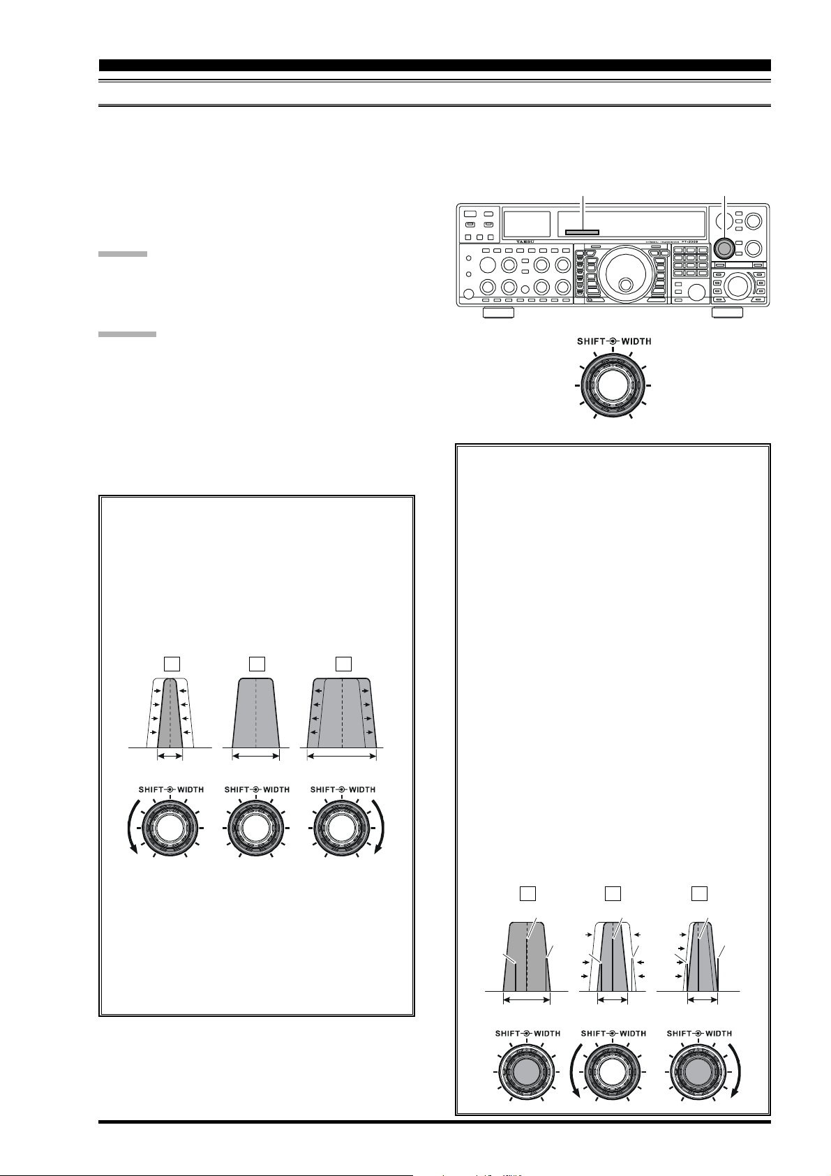
IF SHIFT OPERATION
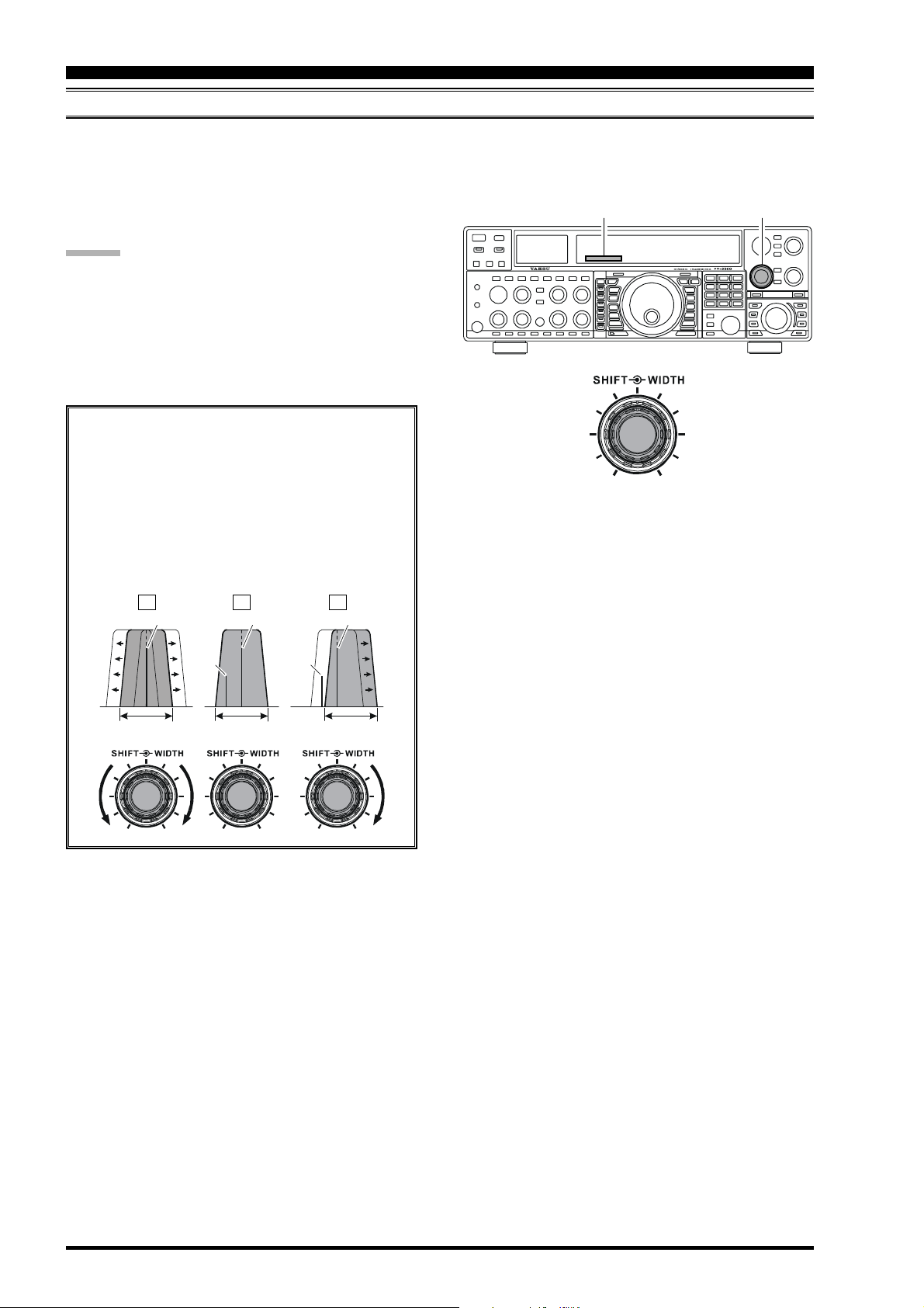
IF Shift allows you to vary the DSP filter passband higher or lower, without changing the pitch of the incoming signal, so as
to reduce or eliminate interference. Because the carrier tuning frequency is not varied, there is no need to re-tune the
operating frequency when eliminating the interference. The total passband tuning range for the IF Shift system is ±1 kHz.
Rotate the [SHIFT] knob to the left or right to reduce the
interference.
ADVICE :
The [SHIFT] knob affects the Main band (VFO-A)
only. However, you may shift the Sub band (VFO-B)
filter passband via Menu items “042 S-iF LSB SET”
through “049 S-iF PKT-USB.”
The position of the passband set by the IF Shift can be
observed on the display.
Referring to Figure “A,” note the depiction of the
IF DSP filter as the thick line, with the [SHIFT
knob in the 12 o’clock position. In Figure “B,” an
interfering signal has appeared inside the original
passband. In Figure “C,” you can see the effect of
rotating the [SHIFT] knob so as to reduce the interference level by moving the filter passband so
that the interference is outside of the passband.
(
SSB/CW/RTTY/PKT/AM MODES
SHIFT Indicator
]
)
[
SHIFT] knob
AB C
Desired Signal Desired Signal Desired Signal
QRMQRM
IF
BANDW IDTH
IF
BANDWIDTH
IF
BANDWID TH
Page 56 FT-2000D OPERATING MANUAL
Page 5
I
NTERFERENCE
R
EJECTION
(S
IGNALS WITHIN
3
)
KHZ
WIDTH (IF DSP BANDWIDTH) TUNING
The IF Width tuning system allows you to vary the width of the DSP IF passband, so as to eliminate interference. Moreover,
the bandwidth may actually be expanded from its default setting, should you wish to enhance incoming signal fidelity when
interference on the band is low.
Rotate the [WIDTH] knob to adjust the bandwidth.
Counter-clockwise rotation reduces the bandwidth, while
clockwise rotation increases the bandwidth.
ADVICE :
The IF Width affects the Main band (VFO-A) only.
The bandwidth of the IF can be observed on the dis-
play.
CAUTION:
When rotating the [WIDTH] control fully counter-clockwise, the transition between 50 Hz and 25 Hz bandwidth
may be accompanied by a “ping” sound, depending on the
amount of noise present. This is a normal condition, and
you should turn down the volume, when wearing headphones, to minimize the amplitude of this momentary
sound.
Referring to Figure B, you can see the default bandwidth with the [WIDTH] knob set to the 12 o’clock
position.
By rotating the [WIDTH] knob to the left, the bandwidth will narrow (see Figure “A”), while rotation
of the [WIDTH] knob to the right, as depicted in
Figure “C,” will widen the bandwidth.
AB C
(
SSB/CW/RTTY/PKT MODES
WIDTH Indicator
Using IF Shift and Width Together
The IF Shift and Variable IF Width features together
form a very effective interference-fighting filtering system.
For example, in Figure “A” you can see how interference has appeared both on the high and low sides
of the desired signal. By rotating the [WIDTH
knob, as shown in Figure “B,” the interference from
one side can be eliminated, and by re-positioning
the [SHIFT] knob (Figure “C”), the interference
on the opposite side can be removed, without reintroducing the interference previously eliminated
in Figure “B.”
)
[
WIDTH] Knob
]
IF
BANDW IDTH
The default bandwidths, and total bandwidth adjustment range, will vary according to the operating mode:
SSB Mode:
CW Mode:
RTTY/PKT Modes:
200 Hz ~ 4.0 kHz (2.4 kHz)
25 Hz ~ 2.4 kHz (2.4 kHz)
: bandwidth at 12 o’clock position of [WIDTH] knob.
IF
BANDWIDTH
25 Hz ~ 2.4 kHz (500 Hz)
IF
BANDWID TH
Advice: For best interference reduction, the Width
and Shift features are the primary tools you should
use. After narrowing the bandwidth (Width) and/or
adjusting the center of the passband (Shift), the
Contour control may also yield additional signalenhancement benefits on the net residual bandwidth.
What’s more, the IF Notch Filter (see the next section) may also be utilized, in conjunection with the
three other filter systems, to significant advantage.
AB C
Desire d Signal Des ired Signal Desir ed Signal
IF
BANDWID TH
QRMQRM
IF
BANDWID TH
QRM
IF
BANDWID TH
QRMQRMQRM
Page 57FT-2000D OPERATING MANUAL
Page 6
I
NTERFERENCE
R
EJECTION
(S
IGNALS WITHIN
3
)
KHZ
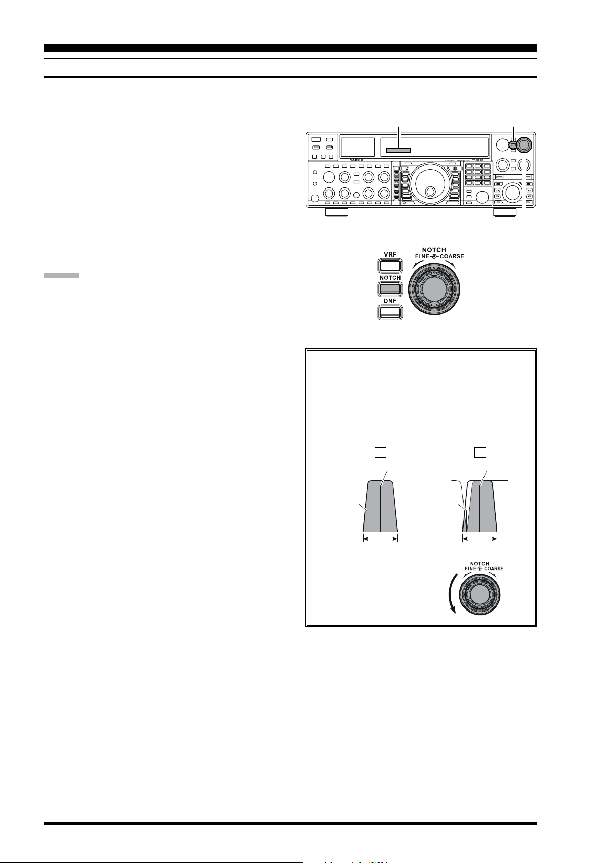
IF NOTCH FILTER OPERATION
The IF Notch filter is a highly-effective system that allows you to slice out an interfering beat note or other carrier signal
from inside the receiver passband.
1. Press the [NOTCH] button. The Notch characteristic
will appear in the display to confirm that the Notch
filter is engaged.
2. Initially, rough adjustment of the center frequency of
the IF Notch Filter is adjusted using the outer
[
COARSE] knob; thereafter, fine tuning of the Notch
frequency is adjusted using the inner [FINE] knob.
3. To switch the IF Notch filter off, press the [NOTCH
button once more. The Notch notation will turn off,
confirming that the IF Notch filter is no longer operating.
ADVICE :
The IF Notch filter affects the Main band (VFO-A)
only.
You may observe the graphically-depicted peak (maxi-
mum null) position of the IF Notch Filter in the NOTCH
indicator on the display.
The width of the IF Notch null may be adjusted using
Menu item “092 rdSP NOTCH W.” Both “Wide” and
“Narrow” selections are available, with “Narrow” providing the least disruption of the “desired” signal.
When the optional DMU-2000 Data Management Unit
is connected, the effect of the IF Notch filter may be
observed on the Audio Scope (on the “Oscilloscope”
page). The Notch will be observed as a “dip” in the
noise platform observed. What’s more, the “Waterfall”
display may be used to observe the effect of the IF
Notch filter, which will appear as a white area in the
colored background area. The tuning rate for the IF
Notch is somewhat slow while you adjust the [FINE
knob, so the use of the Waterfall display to confirm
proper adjustment is highly recommended.
(
SSB/CW/RTTY/PKT/AM MODES
NOTCH Indicator
]
The performance of the IF Notch filter is shown in
Figure “A,” where the effect of rotation of the
[
NOTCH] knobs is depicted. In Figure “B,” you
can see the notching effect of the IF Notch filter as
you rotate the [NOTCH] knobs to eliminate the
incoming interference.
AB
Desired Signal Desired Signal
QRM
]
(Heterodyne)
IF
BANDWIDTH
(Heterodyne)
QRM
)
[
NOTCH] Button
IF
BANDWID TH
[
NOTCH] Knob
Page 58 FT-2000D OPERATING MANUAL
Page 7
I
NTERFERENCE
R
EJECTION
(S
IGNALS WITHIN
3
KHZ
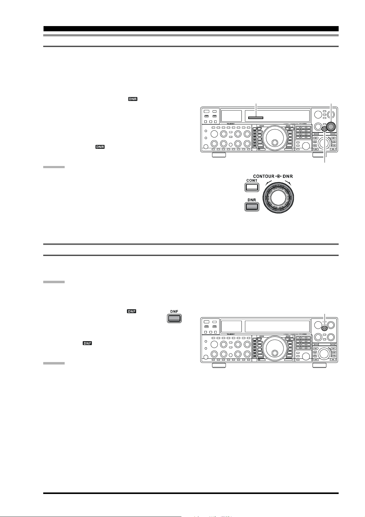
DIGITAL NOISE REDUCTION (DNR) OPERATION
The Digital Noise Reduction (DNR) system is designed to reduce the level of random noise found on the HF and 50 MHz
bands, and it is especially effective during SSB operation. By rotating the [DNR] knob, any of sixteen different noisereduction algorithms can be selected; each of these algorithms was created for dealing with a different noise profile, and
you will want to experiment with the DNR system to find the best setting according to the noise currently being experienced.
)
1. Press the [DNR] button. The “ ” icon will appear
in the display, confirming that the DNR system is engaged.
2. Rotate the [DNR] knob to select the setting that most
effectively reduces the noise level.
3. To disable the DNR system, press the [DNR] button
once more. The “ ” icon will turn off, confirming
that the DNR system is not active.
ADVICE :
The Digital Noise Reduction affects the Main band (VFOA) only.
NOTCH Indicator
[
DNR] Knob
[
DNR] Button
DIGITAL NOTCH FILTER (DNF) OPERATION
The Digital Notch Filter (DNF) is an effective beat-cancelling filter that can null out a number of interfering beat notes
inside the receiver passband. Because this is an Auto-Notch feature, there is no adjustment knob associated with this filter.
ADVICE :
If a very strong interfering carrier is encountered, we recommend you first use the IF Notch filter, as it is the most effective
notching tool in the receiver section.
[
1. Press the [DNF] button. The “ ” icon will
appear in the display, confirming that the DNF
system is engaged.
2. To cancel DNF operation, press the [DNF] button once
more. The “ ” icon will turn off, confirming that
the Digital Notch Filter is no longer in operation.
ADVICE :
The Digital Notch Filter affects the Main (VFO-A) band
only.
DNF] Button
Page 59FT-2000D OPERATING MANUAL
Page 8
I
NTERFERENCE
R
EJECTION
(S
IGNALS WITHIN
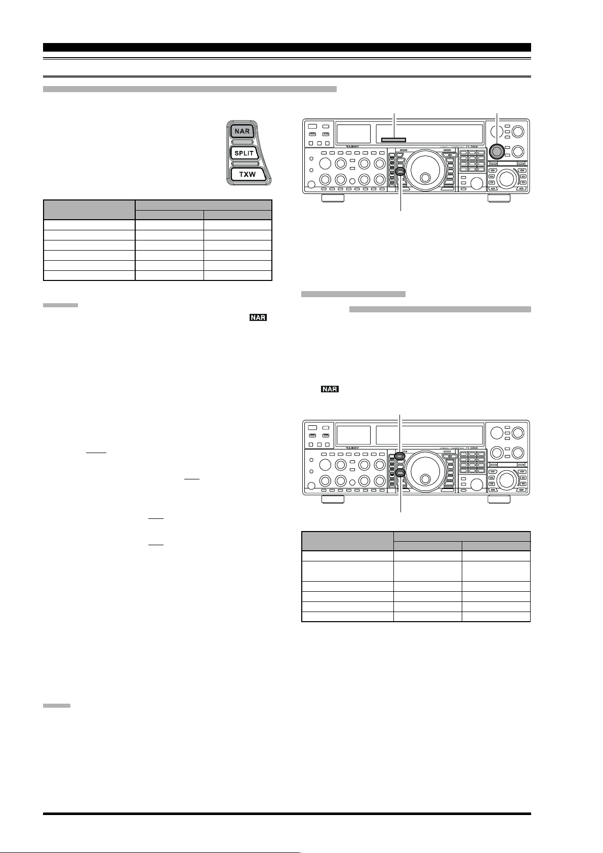
NARROW (NAR) ONE-TOUCH IF FILTER SELECTION
Main band (VFO-A) “One-Touch Narrow” Operation
Pressing the [NAR] button provides one-touch, mode-specific selection of a narrow IF DSP filter setting that does not depend on the setting of
the [WIDTH] knob. Pressing the [NAR] button once more returns the bandwidth control
to the Width/Shift system. The factory default bandwidths are:
[
OPERATING MODE
SSB
CW
RTTY/PKT-L/PKT-U
PKT-FM
AM
FM (28/50 MHz Bands
)
ADVICE :
When the narrow bandwidth is selected, the “ ”
icon will appear in the display and the bandwidth on
the WIDTH indicator in the display will be reduced.
The bandwidth applied when the [NAR] button is
pressed may be adjusted using the Menu. This allows
you to customize a quick-switch “Narrow” bandwidth
matching your operating needs. The default values for
each mode below are underlined.
SSB mode: Menu item “104 rdsP SSB NAR”
200/400/600/850/1100/1350/1500/1650/
1800/1950/2100/2250 Hz
CW mode: Menu item “095 rdsP CW NARR”
25/50/100/200/300/400/500/800/1200/1400/
1700/2000 Hz
PSK mode: Menu item “098 rdsP PSK NAR”
25/50/100/200/300/400 Hz
RTTY mode: Menu item “101 rdsP RTY NAR”
25/50/100/200/300/400 Hz
When the [NAR] button has been pushed so as to en-
gage the narrow filter, the [WIDTH] knob will be disabled, but IF Shift still is operational. For many applications, you may find that simple adjustment of the
[
WIDTH] knob, instead of engaging the Narrow filter,
may be satisfactory for interference reduction.
You may adjust the CW bandwidth using the [WIDTH
knob, even if the narrow filter is engaged. In this case,
available bandwidth selections are 25 Hz ~ 2 kHz.
When you press the [NAR] button in the FM mode,
both the transmit and receive bandwidths are narrowed.
NAR] SWITCH
“ON”
1.8 kHz
500 Hz
300 Hz
9 kHz
6 kHz
9 kHz
: Depends on the [WIDTH] knob
“OFF”
16 kHz
9 kHz
16 kHz
Sub band (VFO-B
1. Press the [B] button.
2. Within five seconds of pressing the [B] button (while
the imbedded orange LED is blinking), press the [NAR
button to toggle the bandwidth between “wide” and
“narrow.” When the narrow bandwidth is selected, the
“ ” icon will appear in the display.
OPERATING MODE
SSB
CW
RTTY/PKT-L/PKT-U
PKT-FM
AM
FM (28/50 MHz bands
]
3
)
KHZ
[
NAR] Button
[
WIDTH] KnobWIDTH Indicator
)
“One-Touch Narrow” Operation
[B]
Button
[
NAR] Button
[
NAR] SWITCH
“ON”
1.1 kHz
1.2 kHz
(300 Hz/500 Hz)
1.2 kHz
9 kHz
)
: Requires the optional CW Narrow Filter
6 kHz
9 kHz
300 Hz: YF-122CN, 500 Hz: YF-122C
“OFF”
2.25 kHz
2.0 kHz
1.2 kHz
16 kHz
9 kHz
16 kHz
]
NOTE:
When the [NAR] button is pressed, the [WIDTH] knob no
longer functions.
Page 60 FT-2000D OPERATING MANUAL
Page 9
I
NTERFERENCE
R
EJECTION
(S
IGNALS WITHIN
3
KHZ
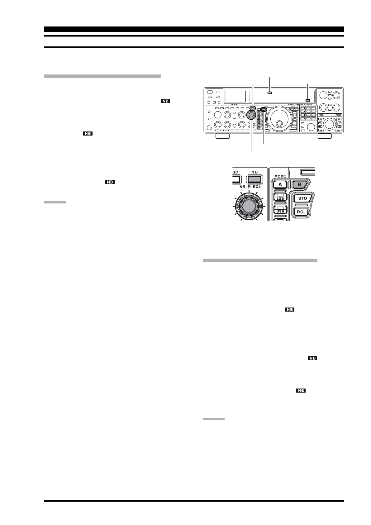
IF NOISE BLANKER (NB) OPERATION
The FT-2000D includes an effective IF Noise Blanker, which can significantly reduce noise caused by automotive ignition
systems.
)
Main band (VFO-A) NB Operation
1. Press the [NB] button momentarily to reduce shortduration pulse noise such as from switching transients,
automobile ignitions and power lines. The “ ” icon
will appear in the display to confirm that the NarrowNB is operating. Press and hold in the [NB] button for
two seconds to reduce longer-duration man-made pulse
noise. The “ ” icon will blink for five seconds, and
thereafter will appear continuously, to confirm that the
Wide-NB is operating.
2. Advance the [NB] knob to the point where the offending noise is best reduced or eliminated.
3. To end Noise Blanker operation, press the [NB] button once more. The “ ” icon will turn off, confirming that the Noise Blanker is no longer in operation.
ADVICE :
When the Roofing filter mode is set to “AUTO” and
the Noise Blanker is turned On, the Roofing Filter bandwidth will automatically be set to 15 kHz. The Roofing Filter may be changed to a narrower selection, as
described previously, although Noise Blanker operation may be compromised somewhat when using a narrower Roofing Filter.
When you change the Noise Blanker level on the Main
(VFO-A) side, the Sub (VFO-B) band’s Noise Blanker
level will automatically change to be the same as that
for VFO-A, if the Sub (VFO-B) band’s Noise Blanker
is engaged.
Main Band (VFO-A) “NB” Icon
[NB]
Button
[NB]
[B]
Knob
Button
Sub Band (VFO-B) “NB” Icon
Sub band (VFO-B) NB Operation
1. Press the [B] button.
2. Within five seconds of pressing the [B] button (while
the imbedded orange LED is blinking), press the [NB
button momentarily to reduce short-duration pulse
noise such as from switching transients, automobile ignitions and power lines. The “ ” icon will appear in
the display to confirm that the Narrow-NB is operating.
3. Within five seconds of pressing the [B] button (while
the imbedded orange LED is blinking), press and hold
in the [NB] button for two seconds to reduce longerduration man-made pulse noise. The “ ” icon will
blink for five seconds, then appear continuously, to confirm that the Wide-NB is operating.
4. To end Noise Blanker operation, press the [B] button,
then press the [NB] button. The “ ” icon will turn
off, confirming that the Noise Blanker is no longer in
operation.
]
ADVIC E:
When you change the Noise Blanker level on the Sub
(VFO-B) side, the Main (VFO-A) band’s Noise Blanker
level will automatically change to be the same as that for
VFO-B, if the Main (VFO-A) band’s Noise Blanker is
engaged.
Page 61FT-2000D OPERATING MANUAL
Page 10
T
OOLS FOR
C
OMFORTABLE AND
E
FFECTIVE
R
ECEPTION
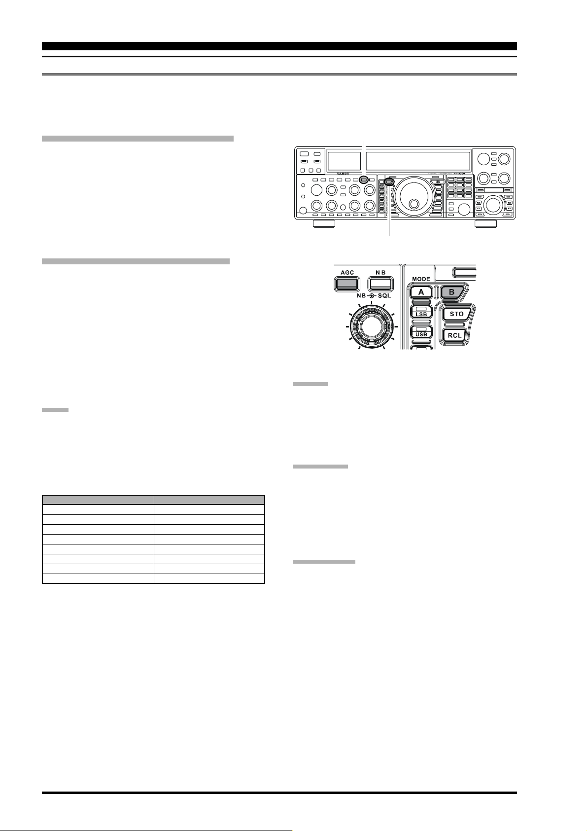
AGC (AUTOMATIC GAIN CONTROL
The AGC system is designed to help compensate for fading and other propagation effects, with characteristics that can be
of particular value on each operating mode. The basic objective of AGC is to maintain a constant audio output level once
a certain minimum threshold of signal strength is achieved.
Main Band (VFO-A) AGC Selection
Press the [AGC] button repeatedly to select the desired
receiver-recovery time constant. You will observe the AGC
status notation in the AGC column of the Receiver Configuration Indicator on the display, denoting the AGC receiver-recovery time currently in use. For most operation,
we recommend the “AUTO” mode. Additionally, you may
disable the AGC by pressing and holding in the [AGC
button for two seconds.
]
)
[
AGC] Button
[B]
Button
Sub Band (VFO-B) AGC Selection
1. Press the [B] button.
2. Within five seconds of pressing the [B] button (while
the imbedded orange LED is blinking), press the [AGC
button repeatedly to select the desired receiver-recovery time constant. You will observe the AGC notation
below the Sub frequency on the display, denoting the
Sub receiver’s current AGC receiver-recovery time. For
most operation, we recommend the “AUTO” mode.
Additionally, you may disable the AGC by pressing
and holding in the [AGC] button for two seconds.
NOTE:
Pressing the [AGC] button allows selection of the desired
receiver-recovery time constant. Normally, the “AUTO”
selection is satisfactory for most situations, but in the event
of operation on a crowded band where you wish to receive
a weak signal, you may wish to change the setting (to FAST,
for example). The “AUTO” mode selections are:
OPERATING MODE
LSB
USB
CW
AM
FM
RTTY
PKT (FM
PKT (LSB
)
)
AUTO AGC SELECTION
SLOW
SLOW
FAST
FAST
FAST
SLOW
FAST
SLOW
]
ADVIC E:
If the AGC receiver-recovery time is set to “Off” by pressing and holding in the [AGC] button, the S-meter will no
longer deflect. Additionally, you will likely encounter distortion on stronger signals, as the IF amplifiers and the
following stages are probably being overloaded.
QUICK POINT
Several aspects of AGC performance may be configured
via the Menu. However, because AGC can have such a
profound impact on overall receiver performance, we generally do not recommend any changes to the AGC Menu
selections until you are thoroughly familiar with the performance of the FT-2000D.
TERMINOLOGY:
Automatic Gain Control, or AGC, is a circuit that senses
the incoming signal strength, and then limits the gains of
the RF and IF stages so as to keep the output audio volume at a more-or-less constant level. AGC also protects
the RF, IF, Audio, and DSP stages from overload, as it
limits the signal strength that is allowed to flow, irrespective of the input signal level.
Page 62 FT-2000D OPERATING MANUAL
Page 11
T
OOLS FOR
C
OMFORTABLE AND
E
FFECTIVE
R
ECEPTION
AGC (AUTOMATIC GAIN CONTROL
)
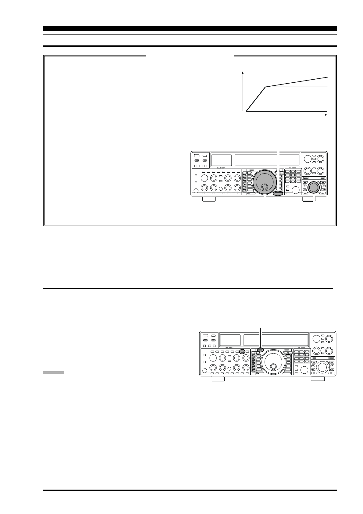
SLOPED AGC Operation
In traditional AGC systems, the audio output from the transceiver becomes essentially fixed once the threshold for
AGC action is reached (usually several dozen dB above the no-signal noise
floor). The FT-2000D, however, includes an innovative Sloped AGC system on the Main band (VFO-A) receiver, that allows the audio volume to
rise and fall slightly according to signal strength. Although the rise/fall slope
is not dramatic, it is sufficient to allow you to use your ear to discern and
separate signals according to signal strength, not just audio frequency.
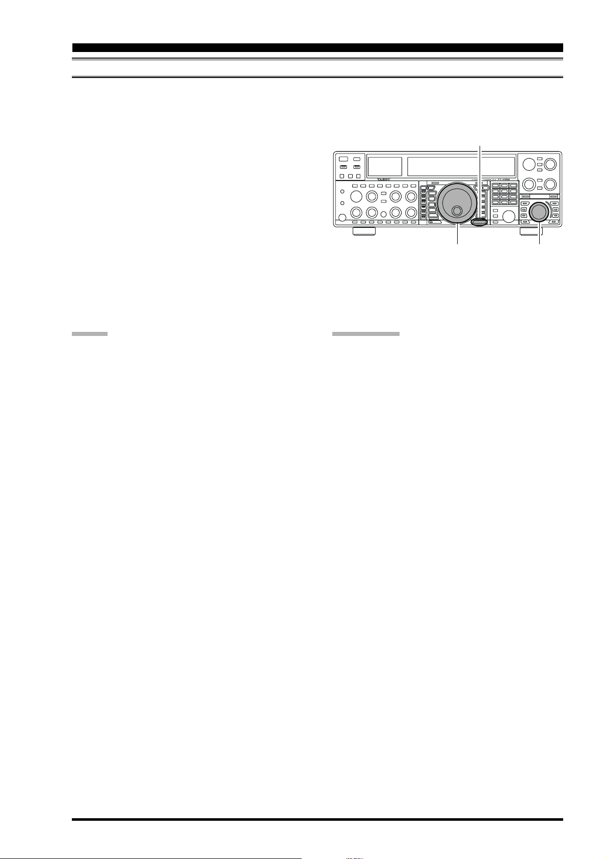
Using Sloped AGC
1. Press the [MENU] button momentarily to enter the
Menu mode.
2. Use the Main Tuning Dial knob to select Menu item
“088 rout AGC SLP.”
3. Rotate the [SUB VFO-B] knob to change the setting to “SLP.”
4. Press and hold in the [MENU] button for two seconds to save the new setting and exit to normal operation. You will now be using the Sloped AGC
system.
t
u
p
t
u
O
o
i
d
u
A
Input Signal
[
MENU] Button
Main Tuning Dial Knob[SUB VFO-B] Knob
SLOPED
NORMAL
MUTE FEATURE
There may be occasions, during Dual Receive operation, when you want to silence the Main (VFO-A) receiver temporarily so as to concentrate on what’s being received on the Sub (VFO-B) receiver. The Mute feature makes this simple to
accomplish.
Press the Main [RX] LED/switch. The Main (VFO-A) receiver will be silenced, and the green LED in the [RX
switch will blink.
To restore reception on the Main (VFO-A) receiver, just
press the blinking [RX] switch/LED once more.
ADVICE :
If you press the [POWER] switch momentarily while the
transceiver is turned on, the transceiver’s audio will be
muted for three seconds.
(
MAIN (VFO-A) BAND
]
)
Main [RX] Switch
Page 63FT-2000D OPERATING MANUAL
Page 12
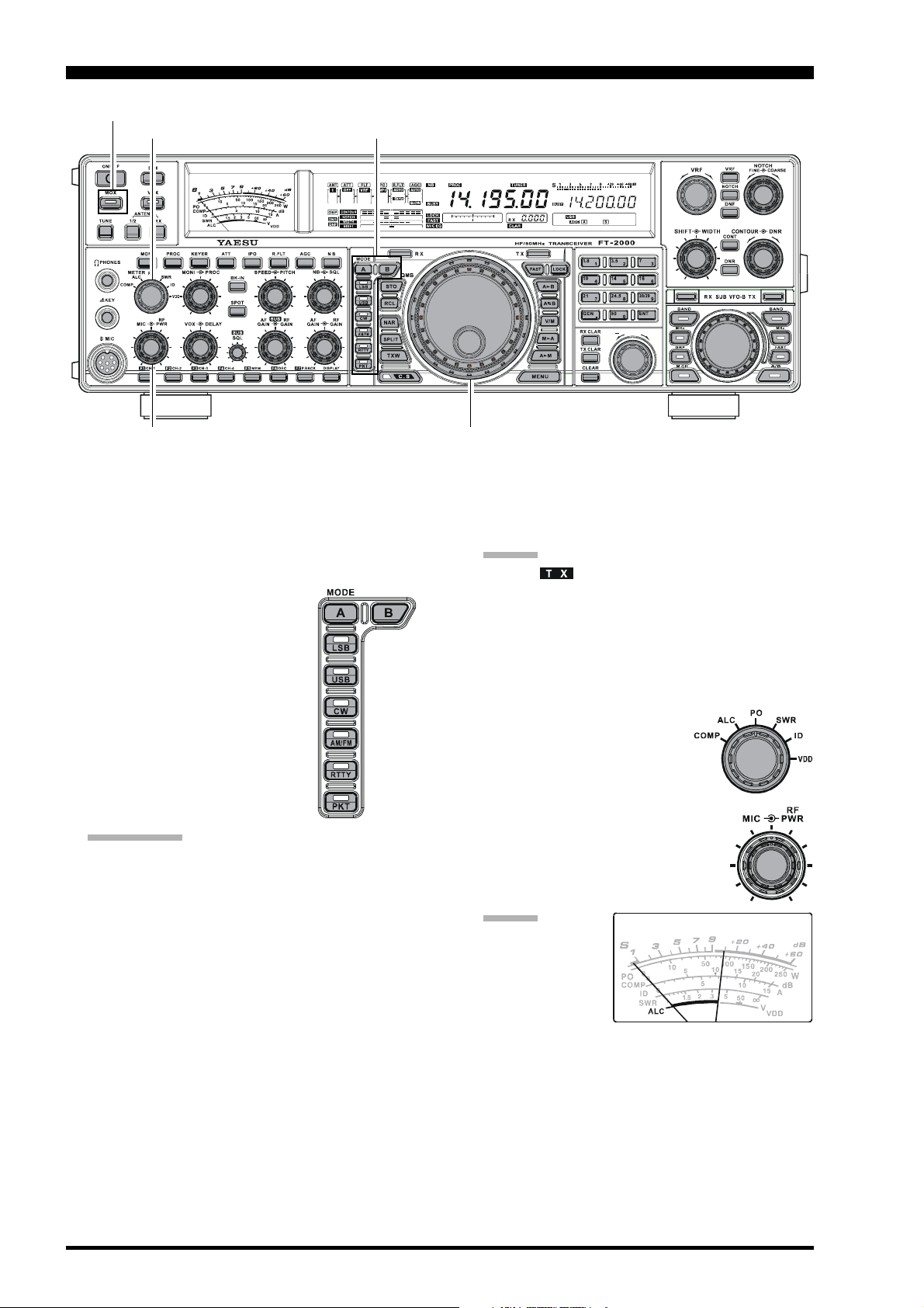
SSB/AM MODE TRANSMISSION
[
MOX] Button
[
METER] Switch
[
MIC] Knob
[
RF PWR] Knob
[
MODE] Button
Main Tuning Dial knob
CLAR
+
1. The operating mode is selected using the [MODE
buttons to the left of the Main Tuning Dial knob, and
the VFO (A or B) to which the selection is applied is
selected by the [A] or [B] button above the [MODE
buttons. Usually, the [A] button glows Red, signifying
that the Main band (VFO-A) is being adjusted. Similarly, pressing the
[B]
button will cause its indicator to
blink Orange for five seconds, signifying Sub band (VFO-B) adjustment. Therefore, press the [A] or [B
]
button to select the desired VFO,
then press the [LSB] or [USB] button to select one of the SSB modes.
For AM operation, press the [AM/
FM] button repeatedly until the im-
bedded LED glows red.
QUICK POINT:
By convention, LSB is used in the 7 MHz and lower
Amateur bands for SSB communication, and USB
is used on the 14 MHz and higher bands (the 10
MHz band is used for CW and data modes only).
When the [AM/FM] button glows orange, it indi-
cates that FM operation is engaged.
2. Rotate the Main Tuning Dial knob to adjust the operating frequency. Alternatively, you may use the [UP]/
[
DWN] scanning buttons on the MH-31B8 Hand Mi-
crophone to sweep up or down the current band.
]
3. Press the microphone’s PTT (Push To Talk) switch to
begin transmission; speak into the microphone in a
normal voice level.
]
ADVIC E:
The “ ” indicator will light up in the frequency
display area, confirming that transmission is in
progress.
When transmitting in the AM mode, rotate the [RF
PWR] knob so as to set a maximum (carrier) power
output of 50 Watts.
4. In the SSB mode, adjust the microphone amplifier gain
to match the microphone and your
voice level, set the [METER
]
switch to the “ALC” position,
close the PTT switch, speak into
the microphone in a normal voice
level, and adjust the [MIC] (gain) knob
so that the ALC voltage (displayed on
the right meter) stays within the ALC
zone of the meter (up to 2/3 of full scale
deflection) on voice peaks.
ADVIC E:
The microphone
gain of the AM
mode has been programmed, at the
factory, to a level
that should be satisfactory for most situations. However, using Menu item “050 A3E MICGAIN,” you may
set a different fixed value, or choose the “Ur” option,
which then lets you use the front panel [MIC] knob to
set the microphone gain in the AM mode. In this case,
the [MIC] knob should not be advanced to the point
where the ALC meter deflects. In many cases, the same
setting as used on SSB will be satisfactory.
5. Release the PTT switch at the end of your transmission. The transceiver will return to the receive mode.
Page 64 FT-2000D OPERATING MANUAL
Page 13

SSB/AM MODE TRANSMISSION
ADVICE :
ALC meter deflection may be caused by excessive drive
power, but also by reflected power detected in the antenna system. If the impedance presented to the transceiver is different from 50 Ohms, ALC meter action
may be observed that is not related to the proper setting of the [MIC] (gain) knob. Therefore, we recommend that you make [MIC] knob adjustments into a
dummy load or antenna system presenting an impedance very close to 50 Ohms.
Rotate the [RF PWR] knob to set the desired power
output. Clockwise rotation of the [RF PWR] knob will
increase the power. The adjustment
range is between 10 Watts and 200
Watts, and you should always use the
minimum power necessary for maintaining reliable communications.
When performing tests (such as the setup of the [MIC
or [RF PWR] knobs), be sure to check the frequency
before transmitting, so as to avoid interference to others who may already be using the frequency.
Four techniques for exercising Transmit/Receive con-
trol are provided on the FT-2000D, and you may
choose the technique(s) that best suit your operating
needs:
Pressing the microphone’s PTT switch will engage
the transmitter.
The rear panel PTT jack may be connected to a
foot switch or other manual switching device in
order to engage the transmitter.
Pressing the front panel [MOX] button will lock
the transmitter on. Press the [MOX] button again
to return to receive.
The VOX (Voice Operated Xmit) circuit will en-
gage the transmitter automatically when you speak
into the microphone. For details of VOX operation, see page 78.
]
Page 65FT-2000D OPERATING MANUAL
Page 14
USING THE AUTOMATIC ANTENNA TUNER
The Automatic Antenna Tuner (hereinafter referred to as the “ATU”) built into each FT-2000D is crafted to ensure a 50Ohm load for the final amplifier stage of the transmitter. We recommend that the ATU be used whenever you operate on the
FT-2000D.
ADVICE :
The ATU of the FT-2000D, being located inside the station, only adjusts the impedance presented to the transceiver at
the station end of your coaxial cable feedline. It does not “tune” the SWR at the antenna feedpoint itself. When designing and building your antenna system, we recommend that every effort be made to ensure a low SWR at the antenna
feedpoint.
The ATU of the FT-2000D includes 100 memories for tuning data. Eleven of these memories are allocated, one per
Amateur band, so that each band has at least one setting preset for use on that band. The remaining 89 memories are
reserved for the 89 most-recent tuning points, for quick frequency change without the need to retune the ATU.
The ATU in the FT-2000D is designed to match impedances within the range of 16.5 Ohms to 150 Ohms, correspond-
ing to an SWR of 3:1 or less on the HF amateur bands (6 m amateur band: 25 Ohms to 100 Ohms, corresponding to an
SWR of 2:1 or less). Accordingly, simple non-resonant whip antennas, along with random-length wires and the “G5RV”
antenna (on most bands) may not be within the impedance matching range of the ATU.
ATU OPERATION
1. Rotate the [RF PWR] knob fully clockwise (to the
right).
2. Use the Main Tuning Dial knob to set the radio to the
desired operating frequency within the Amateur band.
3. Press the [TUNE] button momentarily to place the ATU
in the transmit line (no adjustment/tuning will occur
yet). The “ ” icon will appear in the display.
QUICK POINT:
The momentary press of the [TUNE] button will turn
the tuner on, and the microprocessor will automatically
select the tuning point closest to the current operating
frequency.
4. Press and hold in the [TUNE] button for two seconds
to begin automatic tuning. The transmitter will be engaged, and the “ ” icon will blink while tuning is
in progress. When the optimum tuning point has been
reached, the radio will return to receive, and the
“ ” icon will again glow steadily (instead of
blinking).
5. While tuning around the band using the Main Tuning
Dial knob, you will observe that the “ ” icon
blinks momentarily every 10 kHz. This momentary
blinking indicates that a new tuning window has been
entered. If you want to save tuning data associated with
this 10 kHz window, repeat step 4 (above) for each
such window. On bands like 1.8 MHz where the impedance may change rapidly, the storage of a number
of tuning points is recommended.
6. To disconnect the ATU from the transmit line, press
the [TUNE] button momentarily. The “ ” icon
will turn off, confirming that the ATU has been turned
off. In the “Off” mode, the transceiver will be directly
connected to the coaxial cable connected to your antenna, and will operate based on whatever impedance
is present at the station end of the coax.
NOTCH Indicator
ADVIC E:
The ATU circuit is located between the final amplifier and
the rear-panel antenna jack; reception is not affected by
the ATU.
QUICK POINT:
As shipped from the factory, only one ATU alignment
point is saved on each Amateur band. This was memorized during the final alignment and performance verification stages on the production line.
The momentary flickering of the “ ” icon occurs
whenever you cross over into a new 10 kHz ATU
memory window.
NOTE:
Please check the operating frequency before beginning the
tuning process, to be sure you are not interfering with others who may already be using the frequency.
TERMINOLOGY:
Antenna Tuner Memories: The microprocessor of the ATU
makes a note of the positions of the tuning capacitors and
the selected inductors, and stores the data for each 10 kHz
window in which tuning has occurred. This eliminates the
need to re-tune every time you return to a frequency on
which you already have completed the tuning process.
[
DNR] Knob
[
DNR] Button
Page 66 FT-2000D OPERATING MANUAL
Page 15
USING THE AUTOMATIC ANTENNA TUNER
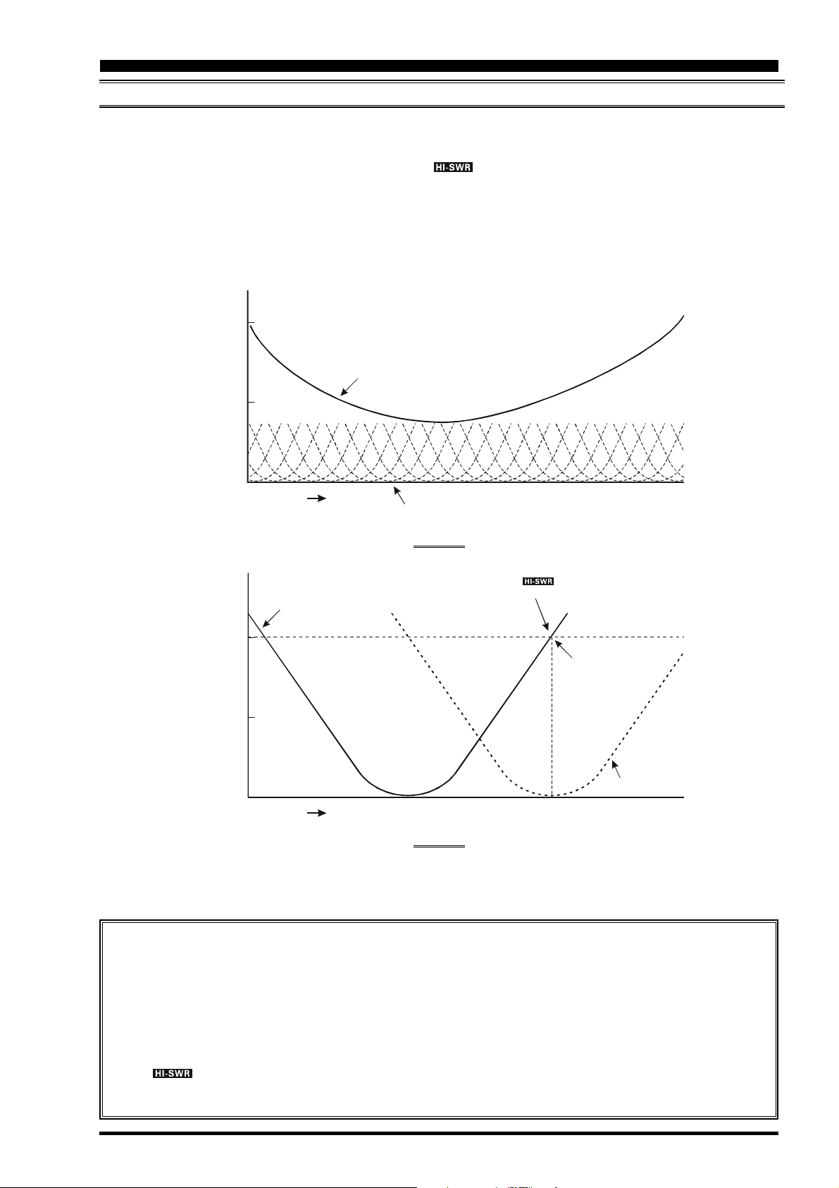
ABOUT ATU OPERATION
Figure 1 depicts a situation where normal tuning via the ATU has been successfully completed, and the tuning data has been
stored in the ATU memory. The antenna system as seen by the transmitter is shown.
In Figure 2, the operator has changed frequency, and the “ ” icon has become appeared. The operator presses and
holds in the [TUNE] button for two seconds to begin impedance matching using the ATU.
If a high SWR conditions exists (above 3:1), corrective action must be taken in the antenna system to bring the impedance
closer to 50 Ohms. Besides the fact that the ATU will refuse to memorize settings on frequencies where the SWR exceeds
3:1, the high SWR may indicate a mechanical failure in the feed system, and such failures can lead to the generation of
spurious signals causing TVI, etc.
SWR: 2.0
Feed Point SWR
SWR: 1.5
SWR: 1.0
SWR: 3.0
SWR: 2.0
SWR: 1.0
Frequency
Memorized ATU Tuning
Frequency
SWR after ATU Tuning
FIGURE 1
FIGURE 2
The “ ” icon appears on the display
when you transmit on this frequenc y
SWR: 3.0
Retuned Setting
About ATU Memories
SWR (Post-tuning) Less than 1.5:1
The tuning settings are committed to the ATU memory.
SWR (Post-tuning) Greater than 1.5:1
Tuning data will not be retained in memory. If you return to the same frequency, the tuning process must be repeated.
SWR (Post-tuning) Greater than 3:1
The “ ” icon will light up, and tuning settings, if achieved, will not be memorized. Please investigate and
resolve the high SWR condition before attempting further operation using this antenna.
Page 67FT-2000D OPERATING MANUAL
Page 16

USING THE AUTOMATIC ANTENNA TUNER
LITHIUM BATTERY REPLACEMENT
The memories for the ATU are backed up by a common Lithium backup battery (type CR2032 or equivalent). After two or
more years of heavy use, you may notice that the tuner memories are not being maintained, and that you have to re-tune
when returning to a frequency on which you had previously stored tuning data.
In this case, please replace the ATU Backup Battery using the following procedure:
1. Turn the FT-2000D’s [POWER] switch “off,” then
turn the FP-2000’s [POWER] switch “off.”
2. Unplug the AC cable from the AC jack on the FP-
2000 rear panel, then disconnect the DC cable (having two connectors) from the FT-2000D rear panel.
3. Referring to Figure 1, remove the three screws from each
side of the transceiver and three screws from the top
edge of the rear panel. Slide the top case toward to the
rear about 1/2 inch (1 cm), then remove the top case.
4. Turn the transceiver up side down.
5. Remove the seven screws affixing the bottom case, and
then remove the bottom case (Figure 2).
6. Locate the Lithium battery on the left side of the Control Unit (Figure 3).
7. Turn the BACKUP switch “off.”
8. Follow the guidelines in Figure 4, and remove the old
battery, replacing it with a new one of the identical type.
9. Connect the DC cable (having two connectors) to the
FT-2000D rear panel, then connect the AC cable to
the AC jack on the FP-2000 rear panel.
10
. Turn the FP-2000’s [POWER] switch “on,” then turn
the FT-2000D’s [POWER] switch “on.” Use extreme
caution, as high voltages are present inside the transceiver!
11
. Turn the BACKUP switch “on.”
12
. Turn the FT-2000D’s [POWER] switch “off,” then
turn the FP-2000’s [POWER] switch “off.”
13
. Unplug the AC cable from the AC jack on the FP-
2000 rear panel, then disconnect the DC cable (hav-
ing two connectors) from the FT-2000D rear panel.
14
. Replace bottom case and its seven screws removed in
step 5, and then replace the top case and its nine screws
removed in step 3.
15
. The ATU Backup Battery replacement is now com-
plete.
CAUTION:
Danger of explosion if battery is incorrectly replaced.
Replace only with the same or equivalent type.
QUICK POINT:
When the ATU Backup Battery is replaced, all tuner memories will be erased, and new sets of tuning data will have to
be stored.
Backup Switch
Lithium Backup Battery
After pusing in the direction of the
arrow, move your finger upward.
+
FIGURE 1
Backup Battery
FIGURE 3
Removal of the
FIGURE 2
Installing the
Lithium Backup Battery
Use your fingertip to push in the
indicated direction
+
+
+
NOTES:
FIGURE 4
Use care in the handling and storage of the Lithium battery. It is small, and presents a choking hazard to small children;
therefore keep such batteries out of the reach of children at all times. Do not dispose of Lithium batteries in fire, and do
not attempt to re-charge them under any circumstances.
When opening/closing the case, take care with your screwdriver not to short out internal components, or touch them in
a way that will cause them to short out against other components.
The exhaustion of the ATU backup battery of the FT-2000D is a normal “wear and tear” situation, and the loss of the
backup voltage is not a “defect” or other condition covered by the Limited Warranty on this product. Accordingly, if you
do not feel capable of replacing the battery, and ask a service shop to do so on your behalf, a service fee may apply.
Page 68 FT-2000D OPERATING MANUAL
Page 17
ENHANCING TRANSMIT SIGNAL QUALITY
ADJUSTING THE SSB TRANSMITTED BANDWIDTH
For transmission on SSB, a default bandwidth of 2.4 kHz is provided. This bandwidth provides reasonable fidelity along
with good talk power, and is typical of the bandwidth used for decades during SSB transmission. However, the bandwidth
may be varied by the operator, so as to provide different levels of fidelity or talk power, according to your preferences.
Here’s how to adjust the transmitted bandwidth on SSB:
1. Press the [MENU] button to engage the Menu.
2. Rotate the Main Tuning Dial knob so as to select Menu
item “083 A3J TX BPF.”
3. Rotate the [SUB VFO-B] knob to select the desired
bandwidth. The available selections are 3000/
50-3000/100-2900/200-2800/300-2700/4002600, and the default is 300-2700 Hz. A wider band-
width will provide greater fidelity, while a narrow bandwidth will compress the available transmitter power
into less spectrum, resulting in more “talk power” for
DX pile-ups.
4. Press and hold in the [MENU] button for two seconds
to save the new setting and exit to normal operation.
ADVICE :
The Transmit Monitor is very helpful way of verifying
the effects on fidelity of changing the bandwidth. Pressing the [MONI] button then adjusting the [MONI] knob
for a comfortable listening level while you are transmitting, you will be able to hear the difference in sound
quality as you make changes.
When the optional DMU-2000 Data Management Unit
is connected, you may verify the effect of your adjustments of the transmitted bandwidth by observing the
Audio Scope on the “Oscilloscope” page.
QUICK POINTS:
The higher fidelity associated with wide bandwidth will
be particularly enjoyable on the low bands, during local rag-chew QSOs.
The “3000” setting is a special hi-fidelity setting,
whereby the transmitted bandwidth is in excess of 3
kHz. This selection, in conjunction with judicious adjustment of the Parametric Microphone Equalizer (see
next chapter) can provide truly outstanding fidelity and
very natural-sounding audio.
When using the wider bandwidth selections (especially
“3000”), the apparent power output from the transmitter may seem lower. This is because the available power
from the transmitter is being distributed over a wider
bandwidth, and the power detection circuitry does not
compensate for the effect of the bandwidth selection
(it is calibrated in the default 2.4 kHz bandwidth).
(
SSB MODE
Main Tuning Dial Knob[SUB VFO-B] Knob
)
[
MENU] Button
Page 69FT-2000D OPERATING MANUAL
Page 18
ENHANCING TRANSMIT SIGNAL QUALITY
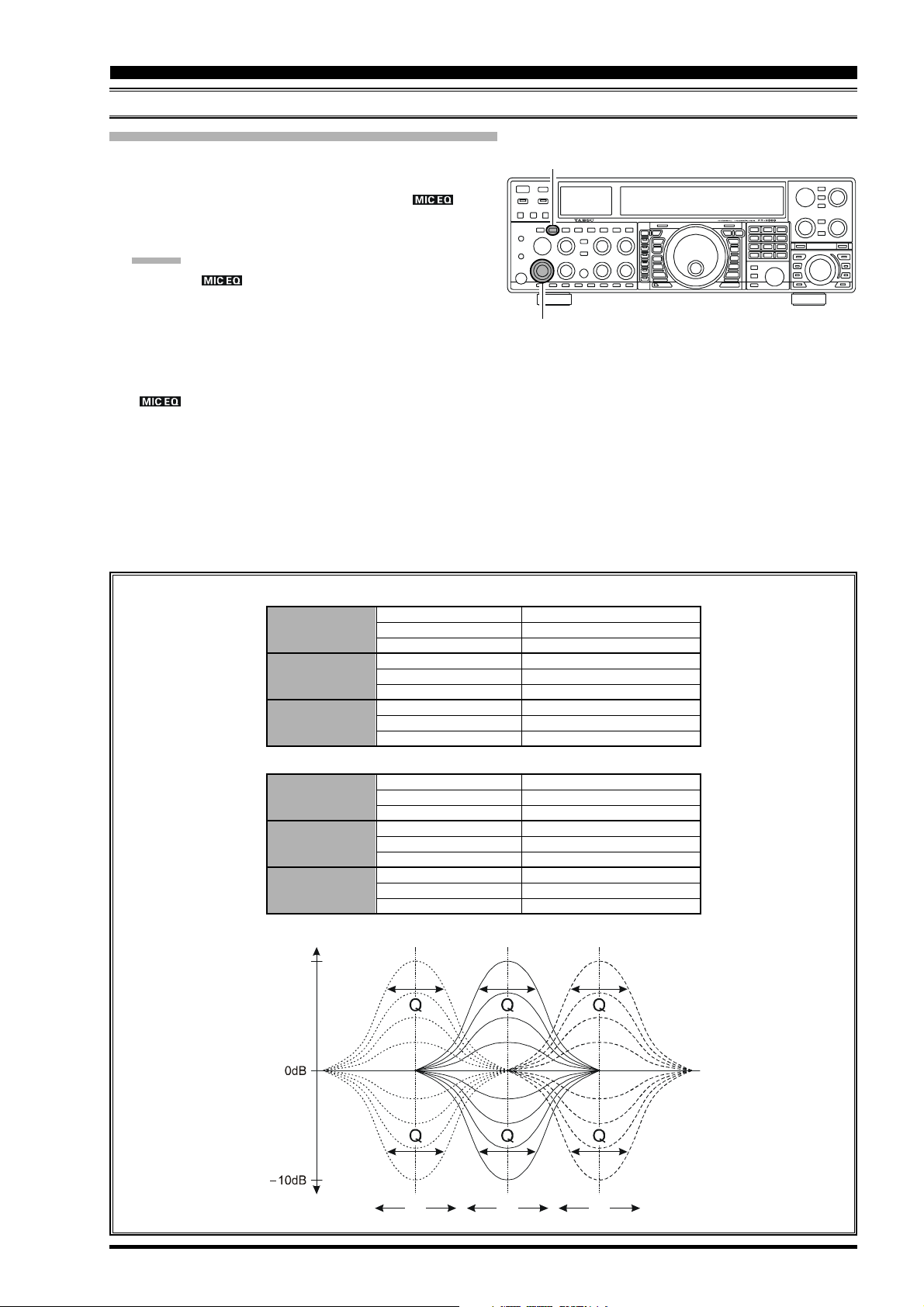
PARAMETRIC MICROPHONE EQUALIZER
The FT-2000D includes a unique Three-Band Parametric Microphone Equalizer, that provides precise, independent control over the low-, mid-, and treble-ranges in your voice wave-form. You may utilize one group of settings for when the
speech processor is off, and an independent group of settings for when the speech processor is on. The speech processor
feature is described on next chapter.
QUICK POINT:
The Parametric Equalizer is a unique technique for adjusting the signal quality. Because the three ranges may be adjusted
so precisely, it is possible to craft a response that provides a more natural and pleasant sound than you have ever experienced before. Effective “talk power” can also be significantly enhanced.
The aspects of configuration that you may adjust on the Parametric Equalizer are:
Center Frequency: The center frequency of each of the three bands may be adjusted.
Gain: The amount of enhancement (or suppression) within each band may be adjusted.
Q: The bandwidth over which the equalization is applied may be adjusted.
(
SSB/AM MODES
)
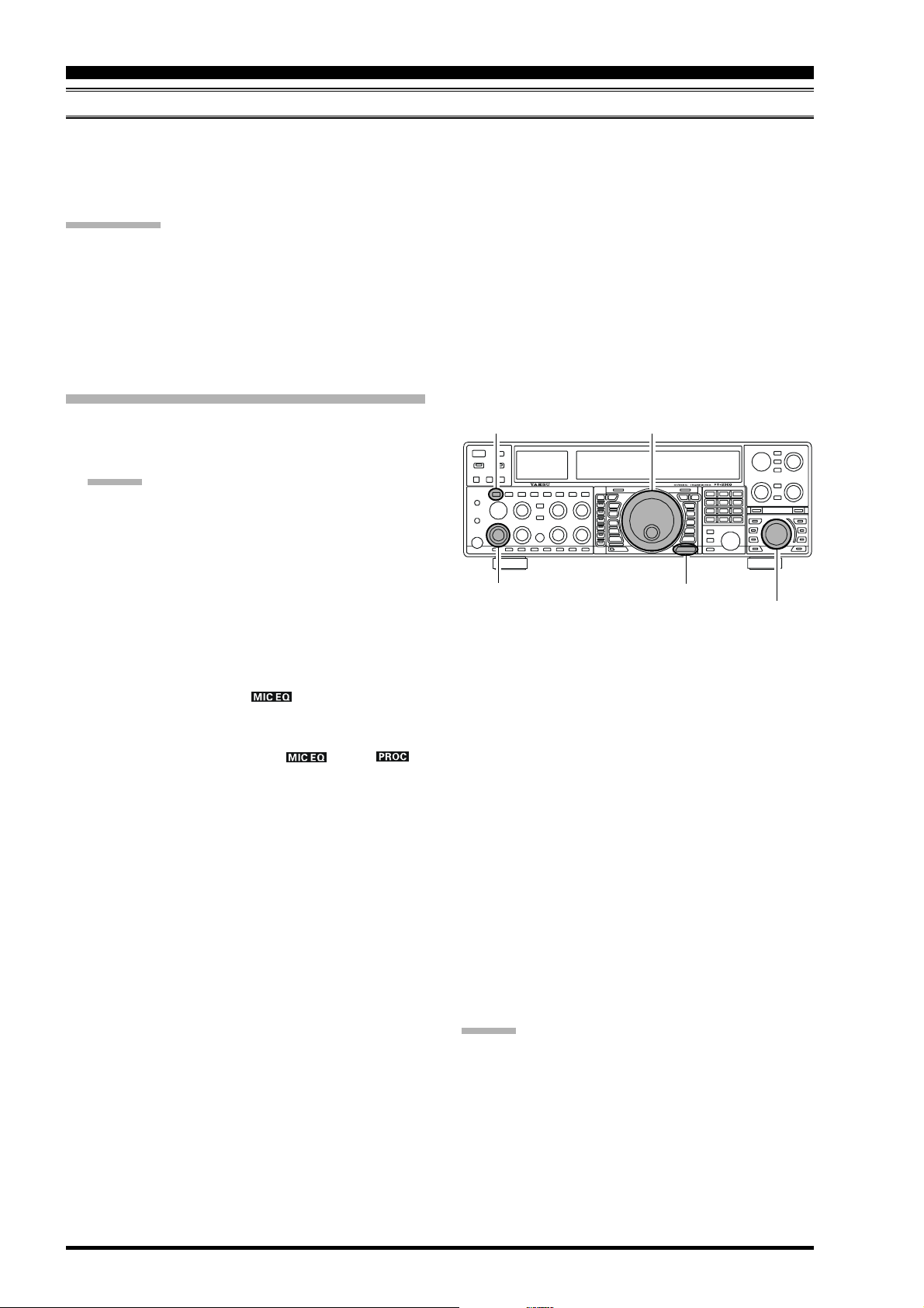
SETUP THE PARAMETRIC MICROPHONE EQUALIZER
1. Connect the microphone to the MIC jack.
2. Set the [RF PWR] knob to its minimum value, so as not
to cause interference to other users during adjustment.
ADVICE :
We recommend you consider connecting a dummy
load to one of the Antenna jacks, and monitor your
signal on a separate receiver, so as to prevent interference to other users.
You will have the best chance of hearing the ef-
fects of adjustments if you wear headphones (connected to the monitor receiver) while monitoring
your transmitted signal.
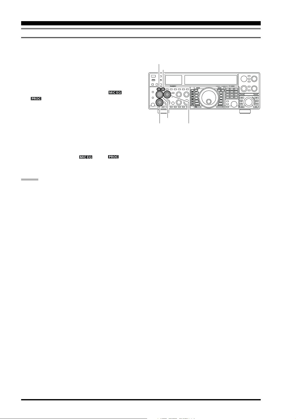
3. If you adjust the Parametric Microphone Equalizer
when the speech processor is disabled, press the
[
PROC] button until the “ ” icon will appear in
the display. If you adjust the Parametric Microphone
Equalizer when the speech processor is engaged, press
the [PROC] button until the “ ” and “ ”
icons will appear in the display.
4. Press the [MONI] button, if you want to listen on the
FT-2000D’s internal monitor.
5. Press the [MENU] button momentarily. The Menu list
will appear in the display.
6. Rotate the Main Tuning Dial knob to find the “EQ”
Menu area, containing Menu items “123” through
“131;” these parameters apply to the adjustment of the
Parametric Microphone Equalizer when the speech
processor is disabled. Menu items “132” through “140”
apply to the adjustment of the Parametric Microphone
Equalizer when the speech processor is engaged.
7. Rotate the [SUB VFO-B] knob to perform adjustments
to a particular Menu item.
8. Close the PTT switch, and speak into the microphone
while listening to the effects of the changes you are making (in step 6). Because the overall effect on the sound
will change with each adjustment you make, you should
make several passes through each adjustment area, to
be sure that you are achieving the optimum setting.
[
MONI] Button
[
RF PWR] Knob
9. When you have completed all adjustments, press and
hold in the [MENU] button for two seconds to save
the new settings and exit to normal operation. If you
only press the [MENU] button momentarily to exit,
any changes you performed will not be stored.
ADVIC E:
To roll off excessive bass response in a wide-range studio
microphone, try putting a 10 dB null at 100 Hz with a
bandwidth of “1” or “2,” do about a 3 dB null centered on
800 Hz with a bandwidth of “3,” and then put an 8 dB
peak centered on 2100 Hz with a bandwidth of “1.” These
are starting recommendations; each microphone and user’s
voice will be different, often requiring different settings.
Main Tuning Dial Knob
[
MENU] Button
[
SUB VFO-B] Knob
Page 70 FT-2000D OPERATING MANUAL
Page 19
ENHANCING TRANSMIT SIGNAL QUALITY
PARAMETRIC MICROPHONE EQUALIZER
ACTIVATES THE PARAMETRIC MICROPHONE EQUALIZER
1. Adjust the [MIC] (gain) knob for SSB use, as described
on page 64.
2. Press the [PROC] button momentarily. The “ ”
icon will appear in the display, confirming that the
Parametric Microphone Equalizer is engaged.
ADVICE
When the “ ” icon blinks, the Parametric Microphone Equalizer setting is not performed.
3. Press the PTT switch on the microphone, and speak
into the microphone in a normal voice level.
4. To switch the Parametric Microphone Equalizer off,
press the [PROC] button several time to disappear the
“ ” icon.
[
PROC] Button
[
MIC] Knob
(
SSB/AM MODES
)
3-STAGE PARAMETRIC EQUALIZER A DJUSTMENTS
Center Frequency “123 tAUd EQ1-FREQ” “100” (Hz) ~ “700” (Hz
Parametric Gain “124 AUd EQ1-LVL”
Q (Bandwidth
3-STAGE PARAMETRIC EQUALIZER A DJUSTMENTS
Center Frequency “132 tAUd PE1-FREQ” “100” (Hz) ~ “700” (Hz
Parametric Gain “133 tAUd PE1-LVL”
Q (Bandwidth
+10dB
n
i
a
G
c
i
r
t
e
m
a
r
a
P
“126 tAUd EQ2-FREQ” “700” (Hz) ~ “1500” (Hz
“129 tAUd EQ3-FREQ” “1500” (Hz) ~ “3200” (Hz
“127 tAUd EQ2-LVL”
“130 tAUd EQ3-LVL”
)
“125 tAUd EQ1-BW”
“128 tAUd EQ2-BW”
“131 tAUd EQ3-BW”
“135 tAUd PE2-FREQ” “700” (Hz) ~ “1500” (Hz
“138 tAUd PE3-FREQ” “1500” (Hz) ~ “3200” (Hz
“136 tAUd PE2-LVL”
“139 tAUd PE3-LVL”
)
“134 tAUd PE1-BW”
“137 tAUd PE2-BW”
“140 tAUd PE3-BW”
(
SPEECH PROCESSOR: “OFF”
(
Low) “–10” (dB) ~ “+10” (dB
(
Mid) “–10” (dB) ~ “+10” (dB
(
High) “–10” (dB) ~ “+10” (dB
(
Low) “1” ~ “10”
(
Mid) “1” ~ “10”
(
High) “1” ~ “10”
(
SPEECH PROCESSOR: “ON”
(
Low) “–10” (dB) ~ “+10” (dB
(
Mid) “–10” (dB) ~ “+10” (dB
(
High) “–10” (dB) ~ “+10” (dB
(
Low) “1” ~ “10”
(
Mid) “1” ~ “10”
(
High) “1” ~ “10”
)
)
)
)
)
)
)
)
)
)
)
)
)
)
f3f2f1
Page 71FT-2000D OPERATING MANUAL
Page 20
ENHANCING TRANSMIT SIGNAL QUALITY
USING THE SPEECH PROCESSOR
(
SSB/AM MODES
)
The FT-2000D’s Speech Processor is designed to increase “talk power” by increasing the average power output via a
sophisticated compression technique, and also adjusting the signal quality to fit the Speech Processor. The result is improved intelligibility when conditions are difficult.
[
1. Adjust the [MIC] (gain) knob for SSB use, as described
MONI] Button
[
PROC] Button
on page 64.
2. Rotate the [METER] switch fully to the left, so as to
select “COMP” (Compression).
3. Press the [PROC] button until the “
“
” icons will appear in the display; this is the
” and
Speech Processor is engaged.
4. Press the PTT switch on the microphone, and speak
into the microphone in a normal voice level. Observe
the deflection of the meter needle on the COMP meter
scale.
[
METER] Switch
[
MIC] Knob
[
RF PWR] Knob
[
MONI] Knob
[
PROC] Knob
5. Rotate the [PROC] knob so that the meter needle deflects to not more than “10 dB” on the COMP scale.
6. To switch the Speech Processor off, press the [PROC
]
button once more. The “ ” and “ ” icons
will turn off, confirming that the Speech processor is
turned off.
ADVICE :
Excessive advancement of the [PROC] knob will re-
sult in a degradation of the transmitted signal’s signalto-noise ratio, thereby reducing intelligibility at the
other end of the circuit.
The Transmit Monitor is very helpful way of verifying
proper adjustment of the compression level. Pressing
the [MONI] button then adjusting the [MONI] knob
for a comfortable listening level while you are transmitting, you will be able to hear the difference in sound
quality as you make adjustments.
The [RF PWR] knob still controls the RF power out-
put, whether or not the Speech Processor is engaged.
You may adjust the Parametric Microphone Equalizer
when the speech processor is engaged, using Menu
items “132” through “140.” See page 70 for details.
When the optional DMU-2000 Data Management Unit
is connected, you may observe the effect of your compression level adjustments by viewing the wave-form
on the “Oscilloscope” page.
Page 72 FT-2000D OPERATING MANUAL
Page 21

ENHANCING TRANSMIT SIGNAL QUALITY
NOTE
Page 73FT-2000D OPERATING MANUAL
Page 22
ENHANCING TRANSMIT SIGNAL QUALITY
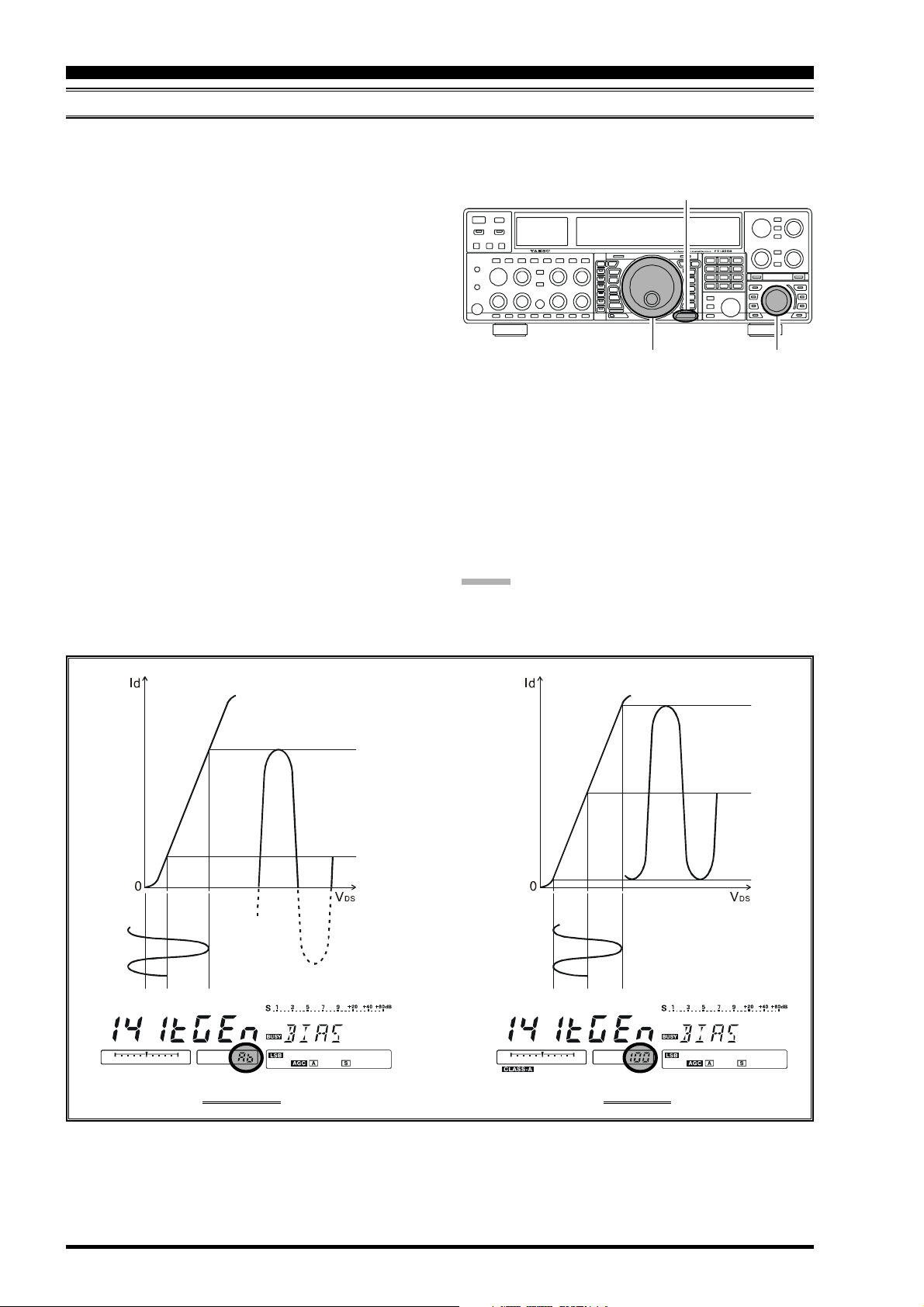
LOW- DISTORTION CLASS-A OPERATION
Class-A operation of the FT-2000D transmitter is provided, yielding ultra-low distortion products during SSB operation.
Power output during Class-A operation is 75 Watts.
[
To engage Class-A operation as following:
1. Press the [MENU] button; the Menu list will appear in
the display.
2. Rotate the Main Tuning Dial knob to select Menu item
“141 tGEn BIAS.”
3. Rotate the [SUB VFO-B] knob to select the desired
BIAS level “0 - 100” to set the transceiver for operation anywhere between Class-A and Class-AB (which
has lower heat dissipation but higher distortion products).
Clockwise rotation of the [SUB VFO-B] knob increases the BIAS, and menu setting “100” will place
the transmitter in fully Class-A operation. Counterclockwise rotation of the [SUB VFO-B] knob will
move the transmitter toward Class-AB operation, and
menu setting “Ab” will place the transmitter in fully
Class-AB operation.
4. Press and hold in the [MENU] button for two seconds
to save the new setting and exit to normal operation.
To exit from the Class-A mode, repeat the above procedure, rotating the [SUB VFO-B] knob to select “Ab” in
step 3 above.
Main Tuning Dial Knob[SUB VFO-B] Knob
ADVIC E
We recommend that menu item “141 tGEn BIAS” is programmed to [C.S] button for easy class-A operation.
MENU] Button
Id: Drain Current
VDS: Drain Voltage
CLASS-AB CLASS-A
Page 74 FT-2000D OPERATING MANUAL
Page 23
ENHANCING TRANSMIT SIGNAL QUALITY
LOW- DISTORTION CLASS-A OPERATION
ADVICE
During Class-A operation, ten Amps of Bias current will be flowing, regardless of the modulation level that leads to
actual power output. Therefore, if the ambient temperature in your operation location is high, the transceiver temperature may rise as well, due to the high bias level (which must be dissipated as heat). Depending on the temperature, you
may wish to reduce the BIAS level using menu item “141 tGEn BIAS,” so as to reduce the amount of heat being
generated.
When the optional DMU-2000 Data Management Unit is connected, you can monitor the heat sink temperature on the
after-maket monitor, you can always be aware of a rise in temperature during Class-A operation. Normally, the temperature is below 80 °C; if it rises to near or above this value, however, we recommend you adjust the BIAS level toward
Class-AB (decrease the numerical value) via menu item “141 tGEn BIAS,” so as to reduce the heat being dissipated.
An innovative aspect of the “Class-A” mode is that the actual power output is always limited to 75 Watts. So even
though you might adjust the BIAS lebel in the direction of Class-AB operation, the power output will not rise; this
eliminates the need, for example, to re-tune your linear amplifier, if used.
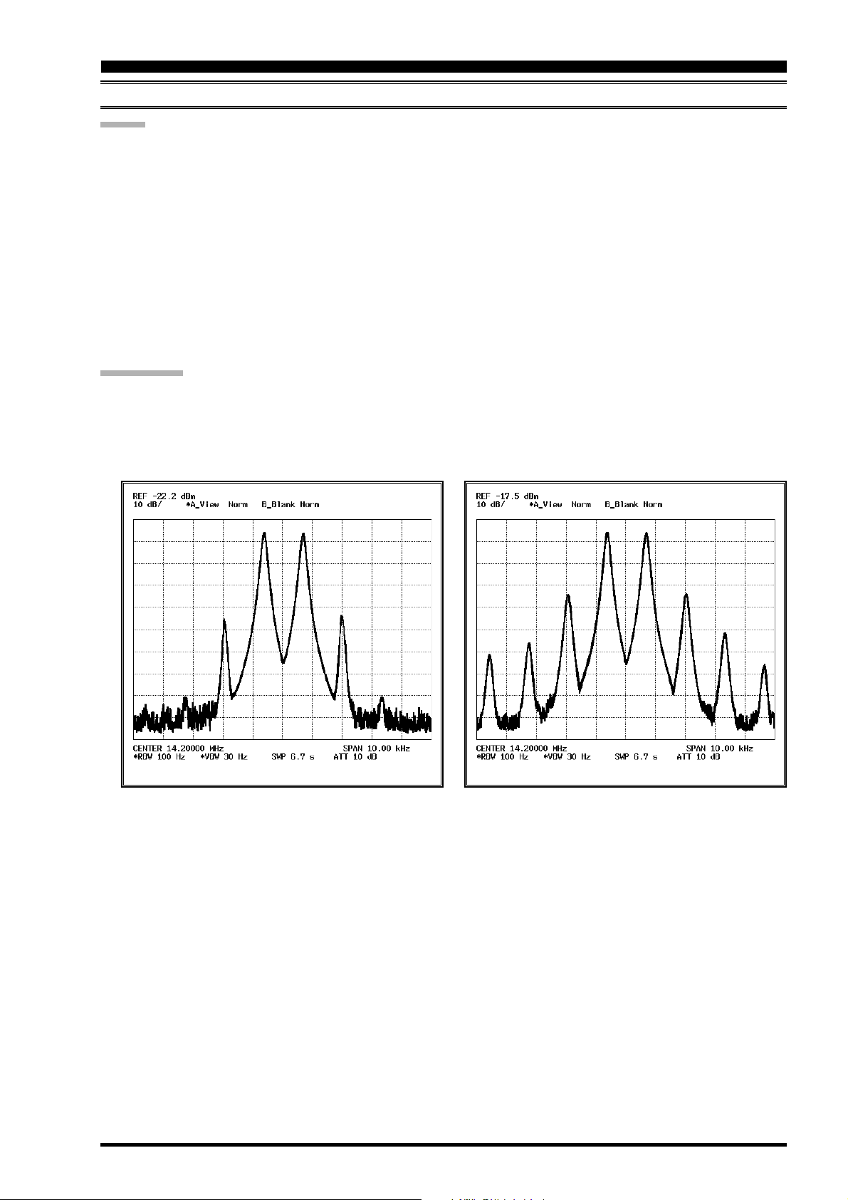
QUICK POINT
Class-A operation provides a significant improvement in transmitter distortion suppression. During Class-A, the 3rd-
order IMD products are typically suppressed 50 dB, while the 5th- and higher-order IMD products (that can cause
“splatter” that interferes with others) will typically be suppressed 70 dB or more.
If you are using a linear amplifier such as the VL-1000, the low distortion produced by the FT-2000D’s transmitter
means that these intermodulation distortion products will not exist to be amplified by your linear.
Class-AB 200W PEP IMDClass-A 75W PEP IMD
High-Power 200-Watt Final Amplifier Stage
The final amplifier stage of the FT-2000D utilizes a pair of ST Micro Electronics Corp. SD2931 MOSFET devices
operating at 50 Volts. The push-pull configuration provides low distortion along with high power output. The 120 mm
thermostatically-controlled cooling fan directs forced air across the heat sink, should the heat sink temperature exceed
the temperature that will trigger the thermostat.
Page 75FT-2000D OPERATING MANUAL
Page 24
TRANSMITTER CONVENIENCE FEATURES
VOICE MEMORY
You may utilize the Voice Memory capability of the FT-2000D for repetitive messages. The Voice Memory system includes four memories capable of storing up to 20 seconds of voice audio each. The maximum that any memory can hold is
20 seconds.
Recording Your Own Voice in Memory
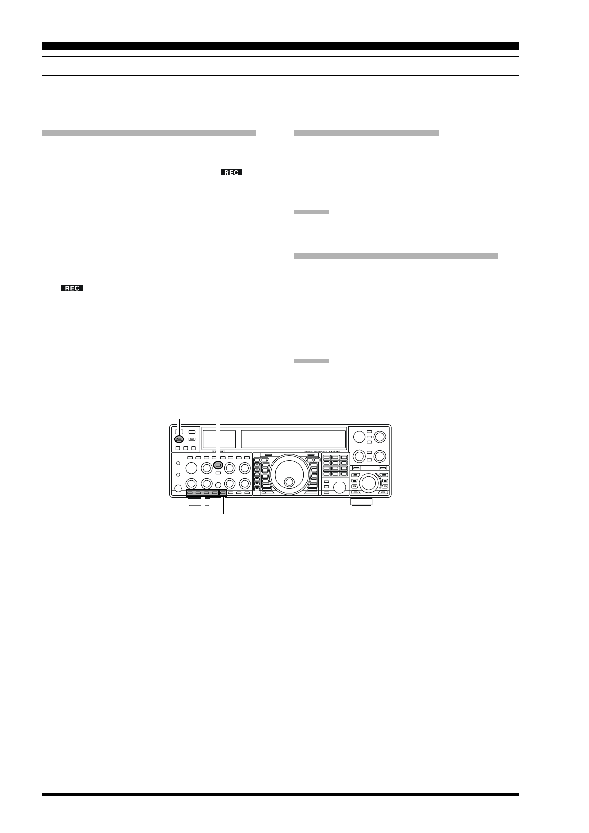
1. Select the LSB, USB, AM, or FM mode using the front
panel [MODE] buttons.
2. Press the [F5(MEM)] button. A blinking “ ” icon
will appear in the display.
3. Within five seconds of pressing the [F5(MEM)] button, press any of the buttons numbered [F1(CH-1
through [F4(CH-4)] to select that memory storage register. If you do not press the PTT switch (see next step)
within five seconds, the memory storage process will
be cancelled.
4. Press the microphone’s PTT switch momentarily, the
“ ” icon will glow steadily, and recording will
begin.
5. Speak into the microphone in a normal voice level to
record the message (such as “CQ DX, CQ DX, this is
W 6 Delta X-Ray Charlie, W 6 Delta X-Ray Charlie,
Over”). Remember that the time limit for recording
any message is 20 seconds.
6. Press the [F5(MEM)] button to terminate the message
storage process.
(
SSB/AM/FM MODES
Checking Your Recording
1. Be sure that the front panel [MOX] button is “Off”
(the LED imbedded in the switch is must be off).
2. Press the [F1(CH-1)] ~ [F4(CH-4)] button (whichever one you just recorded in), and you will hear the
contents of the voice memory you just recorded.
)]
ADVIC E:
You may adjust the playback level of the recording via
Menu item “015 dUS RX LVL.”
Transmitting the Recorded Message
1. Select the LSB, USB, AM, or FM mode using the front
panel [MODE] buttons.
2. Press the front panel’s [BK-IN] button.
3. Press the [F1(CH-1)] ~ [F4(CH-4)] button, depending on which memory register’s message you wish to
transmit. If you hit the key again during playback, the
message will be terminated.
ADVIC E:
You may adjust the transmit (audio) level of the recording
via Menu item “016 dUS TX LVL.”
)
[
MOX] Button
[F1(
[
BK-IN] Button
[F5(
MEM)] Button
CH-1)] ~ [F4(CH-4)] Button
Page 76 FT-2000D OPERATING MANUAL
Page 25
TRANSMITTER CONVENIENCE FEATURES
VOICE MEMORY
(
SSB/AM/FM MODES
)
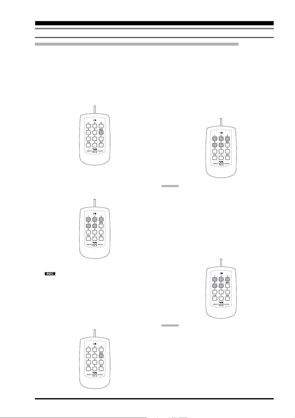
Voice Memory Operation from the optional FH-2 Remote Control Keypad
You may also utilize the Voice Memory capability of the FT-2000D from the optional FH-2 Remote Control Keypad
which plugs into the rear panel’s REM jack.
When using the FH-2 Remote Control Keypad, you may record five memories with up to 20 seconds of voice audio each.
Recording Your Own Voice in Memory
1. Select the LSB, USB, AM, or FM mode using the front
panel [MODE] selector buttons.
2. Press the [MEM] key on the FH-2.
LOCK
OFFON
3. Press any of the FH-2’s keys numbered [1] through
[5]
to select that memory storage register. If you do
not press the PTT key (see next step) within five seconds, the memory storage process will be cancelled.
Checking Your Recording
1. Be sure that the front panel [MOX] button is “Off”
(the LED imbedded in the button must be off).
2. Press the FH-2’s [1] ~ [5] key (whichever one you just
recorded in), and you will hear the contents of the voice
memory you just recorded.
LOCK
OFFON
ADVIC E:
You may adjust the playback level of the recording via
Menu item “015 dUS RX LVL.”
LOCK
OFFON
4. Press the microphone’s PTT switch momentarily, the
“ ” icon will glow steadily, and recording will
begin.
5. Speak into the microphone in a normal voice level to
record the message (such as “CQ DX, CQ DX, this is
W 6 Delta X-Ray Charlie, W 6 Delta X-Ray Charlie,
Over”). Remember that the time limit for recording
any message is 20 seconds.
6. Press the FH-2’s [MEM] key to terminate the message
storage process.
LOCK
OFFON
Transmitting the Recorded Message
1. Select the LSB, USB, AM, or FM mode using the front
panel [MODE] selector buttons.
2. Press the front panel’s [BK-IN] button.
3. Press the FH-2’s [1] ~ [5] key, depending on which
memory register’s message you wish to transmit. If you
hit the key again during playback, the message will be
terminated.
LOCK
OFFON
ADVIC E:
You may adjust the transmit (audio) level of the recording
via Menu item “016 dUS TX LVL.”
Page 77FT-2000D OPERATING MANUAL
Page 26
TRANSMITTER CONVENIENCE FEATURES
VOX
Instead of using the microphone’s PTT switch or the front panel [MOX] switch to activate the transmitter, the VOX (Voice
Operated TX/RX Control) system provides hands-free, automatic activation of the transmitter, based on voice input into
the microphone. Setup of the VOX system takes only a few seconds.
1. To start, set the [VOX] and [DELAY] knobs fully
counter-clockwise (to the left).
2. Press the [VOX] button to engage VOX operation.
3. Speak into the microphone in a normal voice level,
and rotate the [VOX] knob clockwise (to the right) until
the point where your voice input activates the transmitter.
ADVICE :
Do not advance the setting of the [VOX] knob too
much, because to do so will make the transmitter respond to minor background noises in your station.
4. Now stop speaking, and note the amount of time it takes
for the receiver to recover. If the hang time is too long
or too short; rotate the [DELAY] knob, while speaking
briefly into the microphone and then pausing, so as to
set the desired hang time. Clockwise rotation of the
[
DELAY] control will increase the hang time.
5. To exit from VOX operation, press the [VOX] button
once more. We recommend doing this if you are going
to leave your station, to prevent inadvertent activation
of the VOX system by a ringing nearby telephone,
speaker audio from a TV, etc.
(
AUTOMATIC TX/RX SWITCHING USING VOICE CONTROL: SSB/AM/FM MODES
[
VOX] Button
[
VOX] Knob
[
DELAY] Knob
ADVIC E:
The Anti-Trip setting sets the negative feedback of re-
ceiver audio to the microphone, to prevent receiver
audio from activating the transmitter (via the microphone) can be adjusts via Menu item “040 GEnE
ANTIVOX.”
VOX operation may be engaged on either Voice modes
(SSB/AM/FM) and on AFSK-based Data modes. Use
Menu item “137 tGEn VOX SEL” (the selections are
“niC (MIC)” and “dAtA (DATA)”).
)
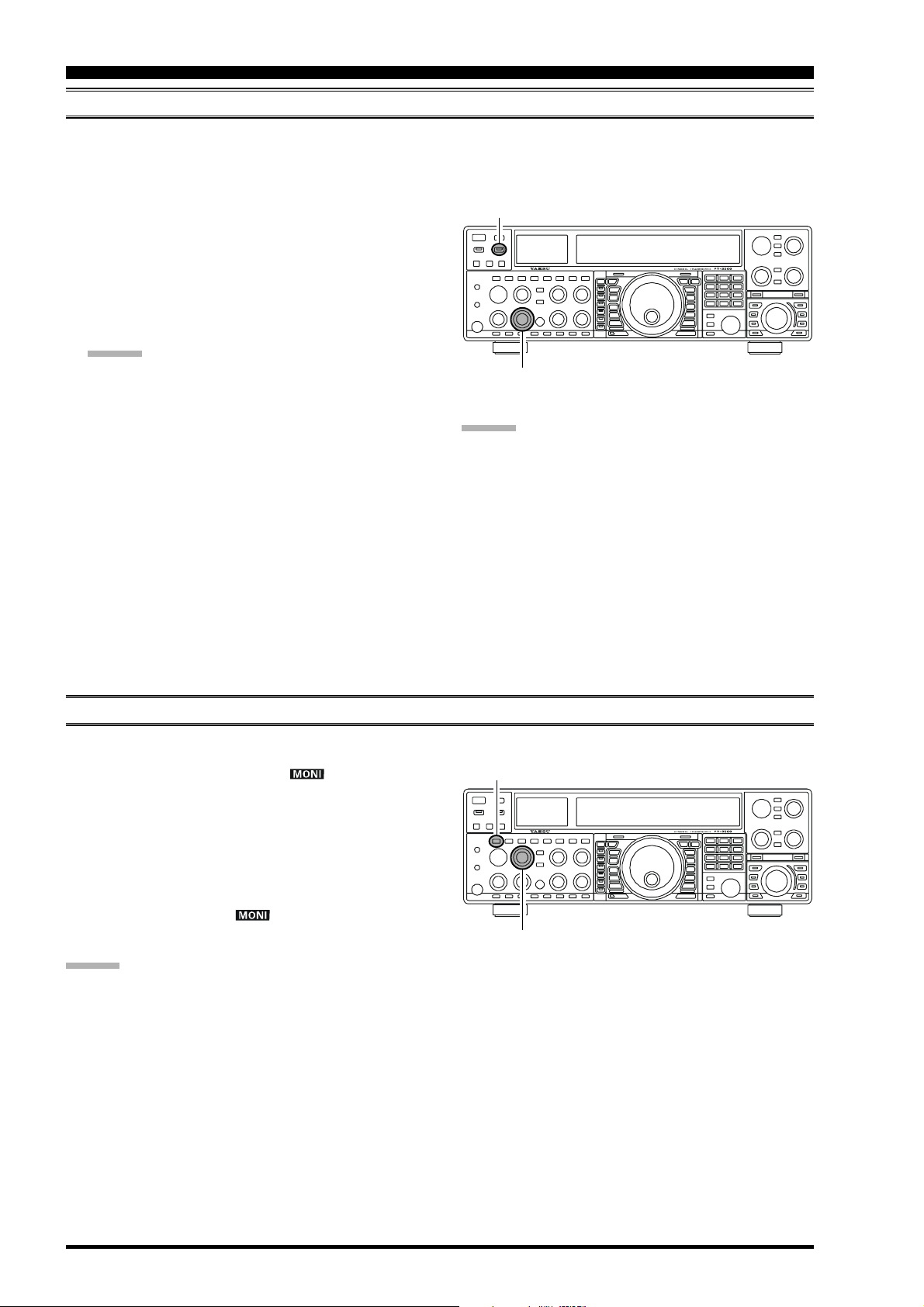
MONITOR
You may listen to the quality of your transmitted signal using the Monitor feature.
1. Press the [MONI] button. The “ ” icon will appear in the display, indicating that the Monitor is turned
on.
2. During transmission, rotate the [MONI] knob to adjust the audio level from the Monitor. Clockwise rotation of this knob will increase the volume level.
3. To switch the Monitor off again, press the [MONI
button once more. The “ ” icon will turn off, confirming that the Monitor is now disengaged.
ADVICE :
If you are using the speaker for monitoring, instead of
headphones, excessive advancement of the [MONI
knob can cause feedback to occur. Additionally, this
feedback can cause the VOX system to hang up in a
loop, making it impossible to return to receive. Therefore, we recommend the use of headphones, if at all
possible, or the minimum usable setting of the [MONI
knob, if the speaker must be used.
Because the Monitor feature utilizes a sampling of the
transmitter’s IF signal, it can be very useful for checking the adjustment of the Speech Processor or Parametric Equalizer on SSB, and for checking the general
signal quality on AM and FM.
(
SSB/AM/FM MODES
[
MONI] Button
]
[
MONI] Knob
]
]
)
Page 78 FT-2000D OPERATING MANUAL
Page 27

TRANSMITTER CONVENIENCE FEATURES
SPLIT OPERATION USING THE TX CLARIFIER
(
VFO-A OPERATION
)
For split TX/RX operation in “casual” pile-ups, where the split is less than 10 kHz, the TX Clarifier (Offset Tuning) feature
may be utilized.
[
CLAR] Knob
1. Press the [TX CLAR] button.
The “TX” icon will appear in the
Multi-Display Window in the display.
QUICK POINT:
The Clarifier is frequently used for receiver offset tuning. However, for DX pile-ups where the DX station is
using a split of less than 10 kHz, the TX Clarifier function is usually the quickest way to set the transmitter to
the desired offset frequency.
2. Rotate the [CLAR] knob to set the desired transmitter
offset. A maximum split of ±9.99 kHz may be set.
3. To exit from TX Clarifier operation, press the [TX
[
RX CLAR] Button
[
TX CLAR] Button
[
CLEAR] Button
CLAR
+
CLAR] button once more. The “TX” icon will disap-
pear from the Multi-Display Window.
ADVICE :
To listen to the pile-up calling the DX station, so as to
find the station currently being worked, you may press
the [RX CLAR] button. Once you have zeroed in on
the station calling the DX (use the SPOT function on
CW for precise alignment of your frequency), you may
then press the [RX CLAR] button again to cancel the
RX Clarifier, and return to reception on the DX station’s
frequency.
Just as with receiver Clarifier operation, the amount of
offset from the original VFO frequency will appear in
the small display window.
As with receiver Clarifier operation, when you turn the
TX Clarifier off the last-used offset is not lost, and will
be available if you turn the TX Clarifier back on. To
clear the Clarifier offset, press the [CLEAR] button.
QUICK POINT:
When attempting to work a DX station on CW, in a splitfrequency pile-up, remember that a large number of other
stations may also be using Yaesu transceivers with capability similar to that of your FT-2000D. On the DX side
of the pile-up, everyone calling precisely on the same CW
frequency will sound like a single tone! So you may have
more success if you use the RX Clarifier to find a hole in
the pile-up, instead of trying to zero-beat the last station
worked by the DX station.
Clarifier Offset Bar Indicator
A visual depiction of the relative offset of the Clarifier may be displayed, using the Bar Indicator.
[
1. Press the [MENU] button; the Menu list will ap-
pear in the display.
2. Rotate the Main Tuning Dial knob to select Menu
item “010 diSP BAR SEL.”
3. Rotate the [SUB VFO-B] knob to select “CLAr”
from the available choices; the factory default is
“C-tn.”
4. Press and hold in the [MENU] button for two sec-
onds to save the new setting and exit to normal operation.
(
TX Frequency
(
TX Frequency
(
TX Frequency
RX Frequency
<
RX Frequency
=
RX Frequency
>
)
)
)
Main Tuning Dial knob[SUB VFO-B] knob
MENU] button
Page 79FT-2000D OPERATING MANUAL
Page 28

TRANSMITTER CONVENIENCE FEATURES
SPLIT-FREQUENCY OPERATION
A powerful capability of the FT-2000D is its flexibility in Split Frequency operation, using the Main (VFO-A) and Sub
(VFO-B) frequency registers. This makes the FT-2000D especially useful for high-level DX-pedition use, as the Split
operation capability is very advanced and easy to use.
1. Set the Main (VFO-A) frequency as desired.
2. Set the Sub (VFO-B) frequency.
3. Now press the [SPLIT] button. The
front panel switch/LEDs will look like
this:
Main (VFO-A)
[RX]
switch “ON” (LED glows
Green)
[TX]
switch “OFF” (LED Off)
Sub (VFO-B)
[RX]
switch “OFF” (LED Off)
[TX]
switch “ON” (LED glows Red)
During Split operation, the Main (VFO-A) register will be
used for reception, while the Sub (VFO-B) register will be
used for transmission. If you press the [SPLIT] button
once more, Split operation will be cancelled.
You may also press the Main [TX] switch located above
and to the right of the Main Tuning Dial knob to return
transmit frequency control to the Main (VFO-A) side,
thereby cancelling Split operation.
ADVICE :
During normal (non-split) VFO-A operation, you may
simply press the Sub (VFO-B) [TX] switch (located
above and to the right of the [SUB VFO-B] knob) to
engage Split operation. The Sub [TX] indicator will
glow Red when you press the switch.
During Split operation, pressing the [A
B] button will
reverse the contents of the Main and Sub VFOs. Press
the [A
B] button once more to return to the original
frequency alignment.
During Split operation, if you press the [RX] switch
above and to the right of the [SUB VFO-B] knob, you
will engage Dual Receive operation, and now can listen to both sides of the DX pile-up, while transmitting
on the Sub (VFO-B) frequency. This is very useful for
maintaining the timing of your calls, while also monitoring both sides of the pile-up.
During Split operation, you may also listen the TX fre-
quency temporarily while pressing the [TXW] button
(below and to the left of the Main Tuning Dial knob).
It is possible to set different operating modes (for ex-
ample, LSB and USB) on the two VFOs used during
Split operation.
During Split operation, it also is possible to set the
Main and Sub VFOs to different Amateur bands. But
remember that Dual Reception must be within the same
band.
MAIN [RX] Switch
[
SPLIT] Button
MAIN [TX] Switch
Sub [RX] Switch
Sub [TX] Switch
VFO Tracking Feature
In the default setting, the Main Band (VFO-A) frequency
and Sub Band (VFO-B) frequency are changed individually using the Main Tuning Dial knob and the [SUB VFO-
B] knob.
If you want to tune the Main Band (VFO-A) frequency
and Sub Band (VFO-B) frequency together, the VFO
Tracking feature is very useful.
Here is the procedure for activating the VFO Tracking feature:
1. Press the [MENU] button to engage the Menu mode.
2. Rotate the Main Tuning Dial knob to select Menu item
“032 GEnE TRACK.”
3. Rotate the [SUB VFO-B] knob to select the desired
Tracking mode.
OFF: Disables the VFO Tracking feature.
bAND: When you change bands on the Main (VFO-
A) side, the Sub (VFO-B) band’s VFO will automatically change to be the same as that of
VFO-A.
FrEq: This function is the almost same as “bAND,”
however, furthermore, the Sub band’s (VFOB) frequency changes together with the Main
Band’s (VFO-A) frequency when turning the
Main Dial Tuning knob.
4. Press and hold in the [MENU] button for two seconds
to lock in the new configuration and exit to normal
operation.
[
MENU] Button
Main Tuning Dial Knob[SUB VFO-B] Knob
Page 80 FT-2000D OPERATING MANUAL
Page 29

TRANSMITTER CONVENIENCE FEATURES
SPLIT-FREQUENCY OPERATION
Quick Split Operation
The Quick Split feature allows you to set a one-touch offset of +5 kHz to be applied to your radio’s transmit
frequency on the Sub (VFO-B), compared to the Main (VFO-A) frequency.
1. Start with regular transceiver operation on the Main (VFO-A) band.
MAIN (VFO-A)
[RX]
switch “ON” (LED glows
Green)
[TX]
switch “ON” (LED glows
Red)
SUB (VFO-B)
[RX]
switch “OFF” (LED Off)
[TX]
switch “OFF” (LED Off)
2. Press and hold in the [SPLIT] button for two seconds to engage the Quick Split feature, and apply a
frequency 5 kHz above the Main (VFO-A) frequency to the Sub (VFO-B) frequency register.
Press and hold in the [SPLIT] button for two seconds to increment the Main (VFO-A) frequency to
+5 kHz.
The VFO configuration will then be:
MAIN (VFO-A)
[RX]
switch “ON” (LED glows Green)
[TX]
switch “OFF” (LED Off)
SUB (VFO-B)
[RX]
switch “OFF” (LED Off)
[TX]
switch “ON” (LED glows Red)
MAIN [RX] Switch
[
SPLIT] Button
MAIN [TX] Switch
Sub [RX] Switch
Sub [TX] Switch
QUICK POINTS:
The operating mode applied to the Sub (VFO-B)
register will be the same as that in use on the Main
(VFO-A) register.
The offset of the Sub (VFO-B) from the Main VFO
(VFO-A) is programmed via the Menu, and is set
to +5 kHz at the factory. Other offsets may be selected, however, using the following procedure:
1. Press the [MENU] button to enter the Menu mode.
[
MENU] Button
2. Rotate the Main Tuning Dial knob to select Menu
item “031 gene Q SPLIT.”
3. Rotate the [SUB VFO-B] knob to select the desired offset.
The available selections are –20kHz ~ +20kHz
(factory default: +5 kHz).
4. When you have completed all adjustments, press
and hold in the [MENU] button for two seconds to
Main Tuning Dial Knob[SUB VFO-B] Knob
save the new setting and exit to normal operation.
If you only press the [MENU] button momentarily
to exit, any changes you performed will not be
stored.
Page 81FT-2000D OPERATING MANUAL
Page 30

CW MODE OPERATION
The powerful CW operating capabilities of the FT-2000D include operation using both an electronic keyer paddle and a
“straight key” or emulation thereof, as is provided by a computer-based keying device.
SETUP FOR STRAIGHT KEY
Before starting, connect your key line(s) to the front and/or rear panel KEY jack(s), and be sure the [KEYER] button on the
front panel is turned off for now.
1. Press the [CW] mode button to engage CW operation.
ADVICE :
The operating mode is selected
using the [MODE] buttons to the
left of the Main Tuning Dial
knob, and the VFO (A or B) to
which the selection is applied is
selected by the [A] or [B] button
above the [MODE] buttons. Usually, the [A] button glow Red, signifying Main band (VFO-A) is
being adjusted. Similarly, pressing the [B] button
will cause its indicator to blink Orange for five seconds, signifying Sub band (VFO-B) adjustment.
Therefore, press the [A] or [B] button to select the
desired VFO, then press the [CW] button to select
the CW mode.
If you press the [CW] button once more, after ini-
tially selecting CW, you will engage the “CW Reverse” mode (see page 86), whereby the “opposite” sideband injection is used, compared to the
“normal” sideband. The CW LED will blink for
three seconds if you select CW Reverse.
2. Rotate the Main Tuning Dial knob to select the desired
operating frequency.
3. Press the [BK-IN] button to engage automatic activation of the transmitter when you close the CW
key. The “ ” icon will appear in the display.
ADVICE :
When you close your CW key, the transmitter will
automatically be activated, and the CW carrier will
be transmitted. When you release the key, transmission will cease after a brief delay; the delay time
is user-programmable, per the discussion on page
83.
As shipped from the factory, the FT-2000D TX/
RX system for CW is configured for “Semi-breakin” operation. However, using Menu item “058
A1A BK-IN,” you may change this setup for full
break-in (QSK) operation, whereby the switching
is quick enough to hear incoming signals in the
spaces between the dots and dashes of your transmission. This may prove very useful during contest and traffic-handling operations.
4. Operation using your CW key may now proceed.
(
AND STRAIGHT KEY EMULATION
[A]
Button
[CW]
[B]
Button
[
BK-IN] Button
ADVIC E:
You can monitor your sending by pressing the [MONI
button, and adjusting the [MONI] knob for a comfortable listening level on the CW sidetone.
If you set the [VOX] and [BK-IN] buttons to Off, you
may practice your sending without having the signal
go out over the air (sidetone only).
If you reduce power using the [RF PWR] knob, the
ALC meter reading will increase; this is normal and
does not indicate any problem whatsoever (because
increased ALC voltage is being used to lower the
power).
TERMINOLOGY:
Semi-break-in
This is a pseudo- “VOX” mode used on CW, whereby
the closure of the CW key will engage the transmitter,
and release of the key will allow the receiver to recover after a short delay. No signals will be heard between the spaces between dots and dashes (unless the
sending speed is extremely slow).
Full break-in
Full break-in (Also known as “Full QSK”) involves
very fast switching between transmit and receive, such
that incoming signals may be heard between the dots
and dashes as you send them. This allows you to hear a
station that suddenly starts transmitting on your frequency, while you are in the midst of a transmission.
Button
)
OPERATION
]
Page 82 FT-2000D OPERATING MANUAL
Page 31

CW MODE OPERATION
USING THE BUILT-IN ELECTRONIC KEYER
Connect the cable from your keyer paddle to the front or rear panel KEY jack.
1. Press the [CW] mode button to engage CW operation.
ADVICE :
The operating mode is selected
using the [MODE] buttons to the
left of the Main Tuning Dial
knob, and the VFO (A or B) to
which the selection is applied is
selected by the [A] or [B] button
above the [MODE] buttons. Usually, the [A] button glow Red, signifying Main band (VFO-A) is
being adjusted. Similarly, pressing the [B] button
will cause its indicator to blinks Orange for five
second, signifying Sub band (VFO-B) adjustment.
Therefore, press the [A] or [B] button to select the
desired VFO, then press the [CW] button to select
the CW mode.
If you press the [CW] button once more, after ini-
tially selecting CW, you will engage the “CW Reverse” mode (see page 86), whereby the “opposite” sideband injection is used, compared to the
“normal” sideband. The CW LED will blink for
three seconds if you select CW Reverse.
2. Rotate the Main Tuning Dial knob to select the desired
operating frequency.
3. Press the [KEYER] button. The “ ” icon will appear in the display, confirming that the builtin Electronic Keyer is now active.
4. Rotate the [SPEED] knob to set the
desired sending speed (4 ~ 60 WPM).
Clockwise rotation of the [SPEED
]
knob will increase the keying speed.
ADVICE :
You may confirm the keying speed when turning
the [SPEED] knob while pressing the [KEYER
button. The Sub (VFO-B) frequency display shows
the keying speed.
When you press either the “Dot” or “Dash” side of
your paddle, the transmitter will automatically be
activated.
5. If you press the [BK-IN] button, “semi-break-in” operation (discussed previously) will be engaged.
6. CW operation utilizing your paddle may now
commence.
ADVICE :
When you utilize your keyer paddle, the transmitter
will automatically be activated, and the CW characters (or a strong of dots and dashes) will be transmitted. When you release the keyer paddle contacts, transmission will cease after a brief delay; the delay time is
user-programmable, per the discussion on page 83.
[
KEYER] Button
[
BK-IN] Button
[
SPEED] Knob
[A]
[CW]
Button
[B]
Button
Button
ADVIC E:
If you reduce power using the [RF PWR] knob, the ALC
meter reading will increase; this is normal and does not
indicate any problem whatsoever (because increased ALC
voltage is being used to lower the power).
]
Full Break-in (QSK) Operation
As shipped from the factory, the FT-2000D TX/
RX system for CW is configured for “Semi-breakin” operation. However, using Menu item “058
A1A BK-IN,” you may change this setup for full
break-in (QSK) operation, whereby the switching
is quick enough to hear incoming signals in the
spaces between the dots and dashes of your transmission.
1. Press the [MENU] button to enter the Menu
mode.
2. Rotate the Main Tuning Dial knob to select
Menu item “058 A1A BK-IN.”
3. Rotate the [SUB VFO-B] knob to set this
Menu item to “FuLL.”
4. Press and hold in the [MENU] button for two
seconds to save the new setting and exit.
Page 83FT-2000D OPERATING MANUAL
Page 32

CW MODE OPERATION
USING THE BUILT-IN ELECTRONIC KEYER
A number of interesting and useful features are available during Electronic Keyer operation.
Setting the Keyer Weight (Dot/Space:Dash) Ratio
The Menu may be used to adjust the Weight for the built-in Electronic Keyer. The default weighting is 3:1 (a dash is
three times longer than a dot or space).
[
1. Press the [MENU] button to enter the Menu mode.
2. Rotate the Main Tuning Dial knob to select Menu
item “060 AIA WEIGHT.”
3. Rotate the [SUB VFO-B] knob to set the weight
to the desired value. The available adjustment range
is for a Dot/Space:Dash ratio of “2.5” ~ “4.5” (default value: “3.0”).
4. When you are finished, press and hold in the
[
MENU] button for two seconds to save the new
setting and exit to normal operation.
Main Tuning Dial Knob[SUB VFO-B] Knob
MENU] Button
Selecting the Keyer Operating Mode
The configuration of the Electronic Keyer may be customized independently for the front and rear KEY jacks of the
FT-2000. This permits utilization of Automatic Character Spacing (ACS), if desired, as well as the use of the
electronic keyer via the front jack and a straight key or computer-driven keying line via the rear panel.
1. Press the [MENU] button to enter the Menu mode.
2. Rotate the Main Tuning Dial knob to select Menu
item “052 A1A F-TYPE” (for the front KEY jack)
or “054 A1A R-TYPE” (for the rear-panel’s KEY
jack).
3. Rotate the [SUB VFO-B] knob to set the keyer to
the desired mode. The available selections are:
OFF: The built-in Electronic Keyer is turned off
(“straight key” mode).
buG: Dots will be generated automatically by the
keyer, but dashes must be sent manually.
ELE: Both dots and dashes will be generated au-
tomatically when you use your paddle.
ACS: Same as “ELE” except that the spacing be-
tween characters is precisely set by the keyer
to be the same length as a dash (three dots in
length)
4. When you are finished, press and hold in the
[
MENU] button for two seconds to save the new
setting and exit to normal operation.
Main Tuning Dial Knob[SUB VFO-B] Knob
ACS “OFF”
Morse
“E” & “T”
ACS “ON”
Morse
“E” & “T”
[
MENU] Button
Inter-character
spacing to short
Page 84 FT-2000D OPERATING MANUAL
Page 33

CW CONVENIENCE FEATURES
CW SPOTTING (ZERO-BEATING
)
“Spotting” (zeroing in on another CW station) is a handy technique for ensuring that you and the other station are precisely
on the same frequency.
For everyday operation, the (CW) [PITCH] knob allows you to set the center of the receiver passband, as well as the offset
pitch of your CW carrier signal, to the tone pitch you prefer to listen to.
The Tuning Offset Indicator in the display may also be moved so you can adjust your receiver frequency to center the
incoming station on the pitch corresponding to that of your transmitted signal.
Using the SPOT System
While pressing the front panel’s [SPOT] button, the Spot
tone will be heard and the Sub (VFO-B) frequency display will show the Spot tone frequency. This tone corresponds to the pitch of your transmitted signal, and if you
adjust the receiver frequency to match the pitch of the received CW signal to that of the Spot tone, your transmitted signal will be precisely matched to that of the other
station.
Release the [SPOT] button to turn the Spot tone off.
ADVICE :
In a tough DX pile-up, you may actually want to use
the SPOT system to find a “gap” in the spread of calling stations, instead of zeroing in precisely on the last
station being worked by the DX station. From the DX
side, if a dozen or more operators (also using Yaesu’s
SPOT system) all call precisely on the same frequency,
their dots and dashes merge into a single, long tone
that the DX station cannot decipher. In such situations,
calling slightly higher or lower may get your call
through.
The Tuning Offset Indicator in the display may be uti-
lized for CW frequency adjustment, as well. Its configuration is set via Menu item “010 diSP BAR SEL”
at the factory, and the Tuning Offset Indicator is already set to the “CW TUNE” selection.
Retune: Shift to Lower Frequency
Zero-In
Retune: Shift to Higher Frequency
: When the CW reversefeature is activated, the
indicator of the Tuning Offset Indicator will also
be reversed.
QUICK POINTS:
The CW Spotting process utilizes the Spot tone or the
Tuning Offset Indicator, with the actual offset pitch
being set by the [PITCH] knob on the front panel. The
offset pitch may be set to any frequency between 300
Hz and 1050 Hz, in 50 Hz steps, and you can either
match tones audibly (using the [SPOT] button) or align
the receiver frequency so that the central red LED on
the Tuning Offset Indicator lights up. Note that there
are 21 “dots” on the Tuning Offset Indicator, and depending on the resolution selected, the incoming CW
signal may fall outside the visible range of the bar indicator, if you are not reasonably close to the proper
alignment of tones.
The displayed frequency, on CW, normally reflects the
“zero beat” frequency of your offset carrier. That is, if
you were to listen on USB on 14.100.00 MHz to a
signal with a 700 Hz offset, the “zero beat” frequency
of that CW carrier would be 14.000.70 MHz; the latter
frequency is what the FT-2000D displays, by default.
However, you can change the display to be identical to
what you would see on SSB by using Menu item “061
A1A FRQDISP” and setting it to “dIr” instead of its
default “OFSt” setting.
[
PITCH] Knob
[
SPOT] Button
Tuning Offset Indicator
Page 85FT-2000D OPERATING MANUAL
Page 34

CW CONVENIENCE FEATURES
USING CW REVERSE
If you experience a difficult interference situation, where an interfering station cannot readily be eliminated, you may wish
to try receiving using the opposite sideband. This may throw the interfering station’s frequency in a direction that may lend
itself more readily to rejection.
[B]
[CW]
Button
Button
Carrier
QRM
Carrier
QRM
1. To start, let’s use a typical example where you have set
the CW mode (using the default “USB” injection) onto
the Main (VFO-A) receiver.
2. Now be sure your mode selection is
still set for the Main (VFO-A) register, and press the [CW] mode button
once more. The “LSB” LED will
blink for three seconds, indicating
that the “LSB” injection side has now
been selected.
3. When using Dual Receive, press the
[B]
button, then (within five seconds
of pressing the [B] button) press the
[CW]
button to engage CW Reverse
on the Sub (VFO-B) receiver, in exactly the same way as for the Main (VFO-A) receiver.
4. Press the [CW] mode button once more to return to
the normal (USB) injection side and cancel CW Reverse operation (the “USB” LED will blink for three
seconds).
NOTES:
When CW Reverse is engaged, the Tuning Offset In-
dicator action will concurrently be reversed as to its
indication.
When the incoming signal pitch tone is properly
aligned, the central red marker lights up whether or
not CW Reverse is engaged.
Retune: Shift to Lower Frequency
Zero-In
In the illustration, Figure A demonstrates the normal CW injection setup, using the USB side. In
Figure B, CW Reverse has been engaged, so as to
receive using LSB-side injection to eliminate interference.
The beneficial effect of switching sidebands can
clearly be seen in this example.
Normal CW
A
( )
USB
RX Passband
CW Reverse
B
( )
LSB
Retune: Shift to Higher Frequency
RX Passband
Page 86 FT-2000D OPERATING MANUAL
Page 35

CW CONVENIENCE FEATURES
CW DELAY TIME SETTING
During semi-break-in (not QSK) operation, the hang time of the transmitter, after you have finished sending, may be
adjusted to a comfortable value consistent with your sending speed. This is the functional equivalent to the “VOX Delay”
adjustment used on voice modes, and the delay may be varied anywhere between 20 milli-seconds ([DELAY] knob set fully
counter-clockwise) and 5 seconds (fully clockwise).
[
1. Press the [BK-IN] button to enable CW transmission
(Menu item “058 A1A BK-IN” must be set to “SEni”).
2. Start sending, and adjust the [DELAY] knob so that
the hang time is as you prefer for comfortable operation.
BK-IN] Button
[
DELAY] Knob
CW PITCH ADJUSTMENT
Rotation of the front panel’s [PITCH] knob will allow
adjustment of the center frequency of the receiver passband, as well as the pitch of your offset CW carrier, to the
tone you prefer. The tone may be varied between 300 Hz
and 1050 Hz, in 50 Hz steps.
ADVICE :
You may confirm the Spot tone frequency when turning
the [PITCH] knob while pressing the [SPOT] button. Sub
(VFO-B) frequency display will shows the Spot tone frequency.
TERMINOLOGY:
CW Pitch: If you tuned to an exact “zero beat” on an
incoming CW signal, you could not copy it (“Zero beat”
implies a 0 Hz tone). Therefore, the receiver is offset several hundreds of Hz (typically), so as to allow your ear to
detect the tone. The BFO offset associated with this tuning (that produces the comfortable audio tone) is called
the CW Pitch.
[
PITCH] Knob
[
SPOT] Button
Sub (VFO-B) frequency display
Page 87FT-2000D OPERATING MANUAL
Page 36

CW CONVENIENCE FEATURES
CONTEST MEMORY KEYER
The FT-2000D in capable of the automatic sending of CW messages (as you might do in a contest). Two techniques for
message storage are available: you may either send the desired message contents using your keyer paddle (“Message
Memory”), or you may input the text characters using the Main Dial Tuning knob and [SUB VFO-B] knobs (“Text
Memory”).
Message Memory
Five memory channels capable of retaining 50 characters total are provided (using the PARIS standard for characters and
word length).
Example: CQ CQ CQ DE W6DXC K (19 characters)
--•--
-- --•-- --•--
•
(
(
)
C
S
TORING A MESSAGE INTO MEMORY
1. Press the [MENU] button to enter the Menu mode.
2. Rotate the Main Tuning Dial knob to select the CW
Memory Register into which you wish to store the
message; for now, we are just selecting the message
entry technique (Keyer entry).
020 tEy CW MEM1
021 tEy CW MEM2
022 tEy CW MEM3
023 tEy CW MEM4
024 tEy CW MEM5
3. Rotate the [SUB VFO-B] knob to set the selected
Memory Register to “tyP2.” If you want to use your
keyer paddle for message entry on all memories, set
all five Menu items (#020 ~ 024) to “tyP2.”
4. Press and hold in the [MENU] button for two seconds
to save the new settings and exit.
)
Q
(
C
•
)
-- --•-- --•--
(
Q
)
(
C
•
)
-- --•-- --
(
)
Q
•-- -- --
•• •
(
(
)
D
--•• --••-- --•--• --•--
••••
(
)
E
W
)
(
)
6
(
(
)
D
X
Main Tuning Dial Knob[SUB VFO-B] Knob
)
[
MENU] Button
(
C
)
(
)
K
M
ESSAGE MEMORY PROGRAMMING
1. Set the operating mode to CW.
2. Set the [BK-IN] button to Off.
3. Turn the internal Electronic Keyer On by pressing the
[
KEYER] button, if necessary.
4. Press the [F5(MEM)] button on the front panel.
5. Press the [F1(CH1)] ~ [F4(CH-4)] button to begin
the memory storage process.
6. Send the desired message using your keyer paddle.
7. Press the [F5(MEM)] button once more at the end of
your message. Up to 50 characters may be stored among
the five memories.
NOTE:
You must exercise care in sending to ensure that the spaces
between letters and words are accurately done; if your timing is off, the spacing may not come out right in the stored
message.
For ease in setting up the keyer memories, we recommend
you set Menu item “051 A1A F-TYPE” and/or “053 A1A
R-TYPE” to “ACS” (Automatic Character Spacing) while
you are programming the keyer memories.
(U
SING YOUR PADDLE
)
[
KEYER] Button
[
BK-IN] Button
[F5(
MEM)] Button
[F1(
CH-1)] ~ [F4(CH-4)] Button
TERMINOLOGY:
PARIS Word Length: By convention in the Amateur
industry (utilized by ARRL and others), the length of one
“word” of CW is defined as the length of the Morse Code
characters spelling the word “PARIS.” This character (dot/
dash/space) length is used for the rigorous definition of
code speed in “words per minute.”
Page 88 FT-2000D OPERATING MANUAL
Page 37

CW CONVENIENCE FEATURES
CONTEST MEMORY KEYER
C
HECKING THE
1. Be sure that Break-in is still turned Off by the [BK-IN
button.
2. Press the [MONI] button to enable the CW monitor.
3. Press the [F1(CH1)] ~ [F4(CH-4)] button to check
your work. You will hear the results in the sidetone,
but no RF energy will be transmitted.
NOTE:
Adjust the monitor level using the [MONI] knob.
CW M
EMORY CONTENTS
[
BK-IN] Button
]
[F1(
CH-1)] ~ [F4(CH-4)] Button
ON-THE-AIR CW M
1. Press the [BK-IN] button to enable transmission. Either Full- or Semi-break-in will be engaged, depending on the setting of Menu item “058 A1A BK-IN.”
2. Press the [F1(CH1)] ~ [F4(CH-4)] button to transmit
the programmed message.
NOTE:
If you subsequently decide to use the “Text Memory” technique for memory storage, please note that the contents of
a message stored using keyer paddle input will not be transferred over when you select “Text Memory technique” on
a particular memory register (the Menu Mode Setting is
set to “tyP1”).
ESSAGE PLAYBACK
[
BK-IN] Button
[F1(
CH-1)] ~ [F4(CH-4)] Button
Transmitting in the Beacon Mode
It is possible to transmit, repetitively in a “Beacon” mode, any message programmed either via paddle input or via
the “Text” input method. The time delay between message repeats may be set anywhere between 0 and 255 seconds
via Menu item “017 tEy BEACON.” If you do not wish the message to repeat in a “Beacon” mode, please set this
Menu item to “off.” Press the [F1(CH1)] ~ [F4(CH-4)] button, depending on the register into which the Beacon
message is stored. Repetitive transmission of the Beacon message will begin. Press one of these keys once more to
halt the Beacon transmissions.
Page 89FT-2000D OPERATING MANUAL
Page 38

CW CONVENIENCE FEATURES
CONTEST MEMORY KEYER
TEXT Memory
The four channels of CW message memory (up to 50 characters total) may also be programmed using a text-entry technique. This technique is somewhat slower than when you send the message directly from your keyer paddle, but accuracy
of character spacing is ensured.
Example 1: CQ CQ CQ DE W6DXC K} (20 characters)
And we will utilize another powerful feature of the CW Memory Keyer, the sequential Contest Number (“Countup”)
feature.
Example 2: 599 10 200 # K} (15 characters)
STORING A MESSAGE INTO MEMORY
[
1. Press the [MENU] button to enter the Menu mode.
2. Rotate the Main Tuning Dial knob to select the CW
Memory Register into which you wish to store the
message; for now, we are just selecting the message
entry technique (Keyer entry).
020 tEy CW MEM1
021 tEy CW MEM2
022 tEy CW MEM3
023 tEy CW MEM4
024 tEy CW MEM5
3. Rotate the [SUB VFO-B] knob to set the selected
Memory Register to “tyP1.” If you want to text message entry on all memories, set all five Menu items
(#020 ~ 024) to “tyP1.”
4. Press and hold in the [MENU] button to save the new
settings and exit.
Main Tuning Dial Knob[SUB VFO-B] Knob
MENU] Button
TEXT MESSAGE PROGRAMMING
1. Press the [CW] mode button to set the operating mode
to CW.
2. Be sure that Break-in is Off by pressing the [BK-IN
button, if necessary.
3. Press the [F5(MEM)] button on the front panel.
4. Press the [F1(CH1)] ~ [F4(CH-4)] button to select
the desired Message Memory Register into which you
wish to program the text.
5. Use the Main Tuning Dial knob to set the cursor position and use the [SUB VFO-B] knob to choose the
letter/number to be programmed in each slot of the
memory. In the case of the second example above, the
“#” character designates the slot where the Contest
Number will appear.
6. When the message is complete, add the “}” character
at the end to signify the termination of the message.
7. Press and hold in the [F5(MEM)] button for 2 seconds
to exit, once all characters (including “}”) have been
programmed.
ADVICE :
Deleting Previously-stored Characters
Use the Main Tuning Dial knob to select the last correct
letter in the message. Now rotate the [SUB VFO-B] knob
to select the “}” character; everything after the “}” character will be deleted.
[
BK-IN] Button Main Tuning Dial Knob
]
[F5(
MEM)] Button
[F1(
CH-1)] ~ [F4(CH-4)] Button
Current Cursor Position
CW Memory Register Number
[
SUB VFO-B] Knob
Message
Cursor
Page 90 FT-2000D OPERATING MANUAL
Page 39

CW CONVENIENCE FEATURES
CONTEST MEMORY KEYER
CHECKING THE CW MEMORY CONTENTS
1. Be sure that Break-in is still turned Off by the [BK-IN
button.
2. Press the [MONI] button to enable the CW monitor.
3. Press the [F1(CH1)] ~ [F4(CH-4)] button to check
your work. You will hear the results in the sidetone,
but no RF energy will be transmitted.
NOTE:
Adjust the monitor level using the [MONI] knob.
ON-THE-AIR CW MESSAGE PLAYBACK
1. Press the [BK-IN] button to enable transmission. Either Full- or Semi-break-in will be engaged, depending on the setting of Menu item “058 A1A BK-IN.”
2. Press the [F1(CH1)] ~ [F4(CH-4)] button to transmit
the programmed message.
NOTE:
If you subsequently decide to use the “Message Memory”
technique for memory storage, please note that the contents of a message stored using text input will not be transferred over when you select “Message Memory technique”
on a particular memory register (the Menu Mode Setting
is set to “tyP2”).
[
]
BK-IN] Button
[F1(
CH-1)] ~ [F4(CH-4)] Button
[
BK-IN] Button
[F1(
CH-1)] ~ [F4(CH-4)] Button
Contest Number Programming
Use this process if you are starting a contest, or if
you somehow get out of sync with the proper number in the middle of a contest.
1. Press the [MENU] button to enter the Menu
mode.
2. Rotate the Main Tuning Dial knob to select
Menu item “019 tEy CONTEST.”
3. Rotate the [SUB VFO-B] knob to set the Con-
test Number to the desired value.
Advice:
Press the [CLEAR] button (located below and
to the left of the [CLAR] knob) to reset the Contest Number to “1.”
4. Press and hold in the [MENU] button for two
seconds to store the new number and exit to
normal operation.
TEXT
DISPLAY CW CODE
!
“””
SN
AF
TEXT
DISPLAY CW CODE
(
“)”
KN
KK
Decrementing the Contest Number
Use this process if the current contest number gets
slightly ahead of the actual number you want to
send (in case of a duplicate QSO, for example).
Press the [F6(DEC)] button on the front panel. The
current Contest Number will be reduced by one.
Press the [F6(DEC)] button as many times as necessary to reach the desired number. If you go too
far, use the “Contest Number Programming” technique desired above.
TEXT
DISPLAY CW CODE
/
“:”
DN
OS
TEXT
DISPLAY CW CODE
@
“[”
@
---
%
#
$
&
‘’’
---
SX
KA
AS
WG
*
---
+
,
---
.
AR
MIM
DU
AAA
;
<
=
>
?
KR
---
BT
---
IMI
\
]
^
_
‘}’
AL
---
---
IQ
---
Page 91FT-2000D OPERATING MANUAL
Page 40

CW CONVENIENCE FEATURES
CONTEST MEMORY KEYER
You may also utilize the CW message capability of the FT-2000D from the optional FH-2 Remote Control Keypad, which
plugs into the rear panel’s REM jack.
(
USING THE OPTIONAL FH-2 REMOTE CONTROL KEYPAD
)
Message Memory
Five memory channels capable of retaining 50 characters total are provided (using the PARIS standard for characters and
word length).
Example: CQ CQ CQ DE W6DXC K (19 characters)
S
TORING A MESSAGE INTO MEMORY
[
1. Press the [MENU] button to enter the Menu mode.
2. Rotate the Main Tuning Dial knob to select the CW
Memory Register into which you wish to store the
message; for now, we are just selecting the message
entry technique (Keyer entry).
020 tEy CW MEM1
021 tEy CW MEM2
022 tEy CW MEM3
023 tEy CW MEM4
024 tEy CW MEM5
3. Rotate the [SUB VFO-B] knob to set the selected
Memory Register to “tyP2.” If you want to use your
keyer paddle for message entry on all memories, set
all five Menu items (#020 ~ 024) to “tyP2.”
4. Press and hold in the [MENU] button to save the new
settings and exit.
Main Tuning Dial Knob[SUB VFO-B] Knob
MENU] Button
Page 92 FT-2000D OPERATING MANUAL
Page 41

CW CONVENIENCE FEATURES
CONTEST MEMORY KEYER
M
ESSAGE MEMORY PROGRAMMING
(U
SING YOUR PADDLE
(
USING THE OPTIONAL FH-2 REMOTE CONTROL KEYPAD
1. Set the operating mode to CW.
2. Set the [BK-IN] button to Off.
3. Turn the internal Electronic Keyer On by pressing the
[
KEYER] button, if necessary.
4. Press the FH-2’s [MEM] key.
LOCK
OFFON
5. Press the [1] ~ [5] key on the FH-2 to begin the memory
storage process.
LOCK
OFFON
)
)
CHECKING THE CW MEMORY CONTENTS
1. Be sure that Break-in is still turned Off.
2. Press the [MONI] button to enable the CW monitor.
3. Press the FH-2’s [1] ~ [5] key to check your work.
You will hear the results in the sidetone, but no RF
energy will be transmitted.
LOCK
OFFON
NOTE:
You may adjust the monitor level using the [MONI] knob.
ON-THE-AIR CW MESSAGE PLAYBACK
1. Press the [BK-IN] button to enable transmission. Either Full- or Semi-break-in will be engaged, depending on the setting of Menu item “058 A1A BK-IN.”
2. Press the FH-2’s [1] ~ [5] key to transmit the programmed message.
6. Send the desired message using your keyer paddle.
7. Press the [MEM] key on the FH-2 once more at the
end of your message. Up to 50 characters may be stored
among the five memories.
LOCK
OFFON
NOTE:
You must exercise care in sending to ensure that the spaces
between letters and words are accurately done; if your timing is off, the spacing may not come out right in the stored
message.
For ease in setting up the keyer memories, we recommend
you set Menu item “052 A1A F-TYPE” and/or “054 A1A
R-TYPE” to “ACS” (Automatic Character Spacing) while
you are programming the keyer memories.
LOCK
OFFON
NOTE:
If you subsequently decide to use the “Text Memory” technique for memory storage, please note that the contents of
a message stored using keyer paddle input will not be transferred over when you select “Text Memory technique” on
a particular memory register (the Menu Mode Setting is
set to “tyP1”).
Page 93FT-2000D OPERATING MANUAL
Page 42

CW CONVENIENCE FEATURES
CONTEST MEMORY KEYER
(
USING THE OPTIONAL FH-2 REMOTE CONTROL KEYPAD
)
TEXT Memory
The five channels of CW message memory (up to 50 characters total) may also be programmed using a text-entry technique. This technique is somewhat slower than when you send the message directly from your keyer paddle, but accuracy
of character spacing is ensured.
Example 1: CQ CQ CQ DE W6DXC K} (20 characters)
And we will utilize another powerful feature of the CW Memory Keyer, the sequential Contest Number (“Countup”)
feature.
Example 2: 599 10 200 # K} (15 characters)
TEXT MEMORY STORAGE
1. Press the [MENU] button to enter the Menu mode.
2. Rotate the Main Tuning Dial knob to select the CW
Memory Register into which you wish to store the
message; we are now selecting the message entry technique (Text entry).
020 tEy CW MEM1
021 tEy CW MEM2
022 tEy CW MEM3
023 tEy CW MEM4
024 tEy CW MEM5
3. Rotate the [SUB VFO-B] knob to set the selected
Memory Register to “tyP1.”
4. Press and hold in the [MENU] button for two seconds
to save the new settings and exit.
Main Tuning Dial Knob
[
MENU] Button
[
SUB VFO-B] Knob
TEXT MESSAGE PROGRAMMING
1. Press the [CW] mode button to set the operating mode
to CW.
2. Be sure that Break-in is Off by pressing the [BK-IN
button, if necessary.
3. Press the FH-2’s [MEM] key.
LOCK
OFFON
4. Press the FH-2’s [1] ~ [5] key to select the desired
Message Memory Register into which you wish to program the text.
LOCK
OFFON
5. Use the FH-2’s [] and [] keys to set the cursor
position and use the [] and [] keys to choose the
]
letter/number to be programmed in each slot of the
memory. In the case of the second example above, the
“#” character designates the slot where the Contest
Number will appear.
LOCK
OFFON
Current Cursor Position
CW Memory Register Number
Message
Cursor
ADVIC E:
You may also use the Main Tuning Dial knob and the
[
SUB VFO-B] knobs to program the message charac-
ters.
Page 94 FT-2000D OPERATING MANUAL
Page 43

CW CONVENIENCE FEATURES
CONTEST MEMORY KEYER
(
USING THE OPTIONAL FH-2 REMOTE CONTROL KEYPAD
6. When the message is complete, add the “}” character
at the end to signify the termination of the message.
7. Press and hold in the FH-2’s [MEM] key for 2 seconds to exit, once all characters (including “}”) have
been programmed.
LOCK
OFFON
ADVICE :
Deleting Previously-stored Characters
Use the FH-2’s [] and [] keys or Main Tuning Dial
knob to select the last correct letter in the message. Now
use the [] and [] keys or [SUB VFO-B] knob to select the “}” character; everything after the “}” character
will be deleted.
)
C
HECKING THE
1. Be sure that Break-in is still turned Off.
2. Press the [MONI] button to enable CW monitor.
3. Press the FH-2’s [1] ~ [5] key to check your work.
You will hear the results in the sidetone, but no RF
energy will be transmitted.
NOTE:
You may adjust the monitor level using the [MONI] knob.
ON-THE-AIR CW M
1. Press the [BK-IN] button to enable transmission. Either Full- or Semi-break-in will be engaged, depending on the setting of Menu item “058 A1A BK-IN.”
2. Press the FH-2’s [1] ~ [5] key to transmit the programmed message.
CW M
EMORY CONTENTS
ESSAGE PLAYBACK
LOCK
OFFON
Decrementing the Contest Number
By pressing the FH-2’s [DEC] key momentarily,
you may reduce the current Contest Number by one.
LOCK
OFFON
LOCK
OFFON
NOTE:
If you subsequently decide to use the “Message Memory”
technique for memory storage, please note that the contents of a message stored using text input will not be transferred over when you select “Message Memory technique”
on a particular memory register (the Menu Mode Setting
is set to “tyP2”).
Page 95FT-2000D OPERATING MANUAL
Page 44

FM MODE OPERATION
BASIC OPERATION
1. Press the [AM/FM] button several
times, until the imbedded LED glows
orange, to select the FM operating
mode.
QUICK POINT:
When the [AM/FM] button glows
red, it indicates AM operation.
2. Rotate the Main Tuning Dial knob
(in the case of Main (VFO-A) operation) to select the desired operating frequency. Pressing the
microphone’s [UP] or [DWN] button will cause frequency change in 5 kHz steps.
3. Press the microphone’s PTT switch (or press the front
panel [MOX] button) to transmit. Speak into the microphone in a normal voice level. Release the PTT or
[
MOX] switch to return to receive.
4. Adjustment of the microphone gain may be accomplished in two ways. At the factory, a default level has
been programmed that should be satisfactory for most
situations. However, using Menu item “072 F3E
MICGAIN,” you may set a different fixed value, or
choose the “ur” option, which then lets you use the
front panel [MIC] knob to set the microphone gain in
the FM mode.
[
MOX] Button
[
AM/FM] Button
ADVICE :
The Transmit Monitor is another helpful way of veri-
fying proper adjustment of the FM MIC Gain. By pressing the [MONI] button then adjusting the [MONI] knob
for a comfortable listening level while you are transmitting, you will be able to hear the difference in deviation as you make adjustments.
FM is only used in the 28 MHz and 50 MHz Amateur
bands covered in the FT-2000D. Please do not use
FM on any other bands.
Page 96 FT-2000D OPERATING MANUAL
Page 45

FM MODE OPERATION
REPEATER OPERATION
The FT-2000D may be utilized on 29 MHz and 50 MHz repeaters.
1. Rotate the Main Tuning Dial knob to the output frequency (downlink) from the repeater.
2. If CTCSS Tone operation is desired/needed, press and
hold in the [AM/FM] button for two seconds to engage the CTCSS mode.
3. Rotate the Main Tuning Dial knob to select the desired
CTCSS mode. If you just need to send the uplink encoding tone, select “tn.” For encode/decode operation,
choose “ts” instead. The available choices are
“oFF” “tn” “ts” “oFF.”
4. Rotate the [SUB VFO-B] knob to select the desired
CTCSS Tone to be used. A total of 50 standard CTCSS
tones are provided (see the CTCSS Tone Chart).
5. Press the [AM/FM] Mode button to select the desired
repeater shift direction. The selections are
“S” “+” “–” “S”
where “S” represents “Simplex” operation (not used
on a repeater).
6. Press and hold in the [AM/FM] button for two seconds
to exit from the repeater setup mode.
7. Close the microphone’s PTT switch (or press the
[
MOX] button) to begin transmission. You will observe
that the frequency has shifted to correspond to the programming you set up in the previous steps. Speak into
the microphone in a normal voice level, and release
the PTT switch or [MOX] button to return to the receive mode.
[
MOX] Button
CTCSS Operation
67.0 69.3 71.9 74.4 77.0 79.7 82.5 85.4
88.5 91.5 94.8 97.4 100.0 103.5 107.2 110.9
114.8 118.8 123.0 127.3 131.8 136.5 141.3 146.2
151.4 156.7 159.8 162.2 165.5 167.9 171.3 173.8
177.3 179.9 183.5 186.2 189.9 192.8 196.6 199.5
203.5 206.5 210.7 218.1 225.7 229.1 233.6 241.8
250.3 251.4
[
AM/FM] Button
Main Tuning Dial Knob[SUB VFO-B] Knob
tn: Tone Encoder
tS: Tone Squelch
oFF: OFF
CTCSS TONE FREQUENCY (Hz
Repeater Shift Direction
–: Minus Shift
+: Plus Shift
S: Simplex
CTCSS Tone Frequency
)
ADVICE :
The conventional repeater shift used on 29 MHz is 100 kHz, while on the 50 MHz band the shift may vary between 500 kHz
and 1.7 MHz (or more). To program the proper repeater shift, use Menu items “073 F3E 28 RPT” (28 MHz) and “074
F3E 50 RPT” (50 MHz), as appropriate.
You may also use “Tone Squelch” whereby your receiver will be kept silent until an incoming signal bearing a
matching CTCSS tone is receiver. Your receiver’s squelch will then open in response to the reception of the required
tone.
1. Rotate the Main tuning Dial to the output frequency
[
(downlink) from the repeater.
AM/FM] Button
2. Press and hold in the [AM/FM] button for two sec-
onds to engage the CTCSS mode.
3. Rotate the Main Tuning Dial to choose “ts” from
the available choices of
“oFF” “tn” “ts” “oFF.”
4. Rotate the [SUB VFO-B] knob to select the de-
sired CTCSS Tone to be used. A total of 50 standard CTCSS tones are provided (see the CTCSS
Main Tuning Dial Knob[SUB VFO-B] Knob
Tone Chart).
5. Press and hold in the [AM/FM] button for two sec-
onds. On the display, just below the “10 Hz” fre-
Tone Decoder “ON”
quency digit, a small “d” will indicate that the Tone
Decoder is engaged.
Page 97FT-2000D OPERATING MANUAL
Page 46

MEMORY OPERATION
CONVENIENT MEMORY FUNCTIONS
The FT-2000D contains ninety-nine regular memories, labeled “01” through “99,” nine special programmed limit memory
pairs, labeled “P-1L/1U” through “P-9L/9U,” and five QMB (Quick Memory Bank) memories, labeled “C-1” through
“C-5.” Each stores various settings, not only the Main band’s (VFO-A) frequency and mode (See below). By default, the 99
regular memories are contained in one group; however, they can be arranged in up to six separate groups, if desired.
QUICK POINT:
The FT-2000D’s memory channels store the following data (not just the operating frequency):
Frequency
Mode
Clarifier status and its Offset Frequency
ANT status
ATT status
IPO status
VRF status
Roofing filter status and its Bandwidth
Noise Blanker status
CONTOUR status and its Peak Frequency
DSP Noise Reduction (DNR) status and its Reduction algorithm selection.
DSP Notch filter (NOTCH) status
NAR bandwidth status
DSP Auto Notch filter (DNF) status
Repeater Shift Direction and Shift Frequency
CTCSS status and Tone Frequency
REGULAR MEMORY CHANNELS PMS MEMORY CHANNELS
99 P-9L/9U
98 P-8L/8U
97
03
02
01
P-3L/3U
P-2L/2U
P-1L/1U
P-6L/6U
P-5L/5U
P-4L/4U
QMB MEMORY CHANNEL
P-7L/7U
Page 98 FT-2000D OPERATING MANUAL
Page 47

MEMORY OPERATION
QMB (QUICK MEMORY BANK
The Quick Memory Bank consists of five memories (labeled “C-1” through “C-5.”) independent from the regular and PMS
memories. These can quickly store operating parameters for later recall.
)
QMB Channel Storage
[
1. Tune to the desired frequency on the Main (VFO-A)
band.
2. Press the blue [QMB(STO)] button. The
“beep” will confirm that the contents of
the Main (VFO-A) band have been written to the currently-available QMB
memory.
If you repeatedly press the [QMB(STO)] button, the QMB
memories will be written in the following order:
C-2 C-3 C-4 C-5 C-1
Once all five QMB memories have data on them, previous
data (starting with channel “C-1”) will be over-written on
a first-in, first-out basis.
......
QMB(STO)] Button
QMB Channel Recall
[
1. Press the [QMB(RCL)] button. The current QMB
channel’s data will be shown on the Main
(VFO-A) frequency display field and the
QMB memory channel number will be
shown in the Multi-Display Window.
2. Repeatedly pressing the [QMB(RCL)] button will
toggle you through the QMB channels:
C-2 C-3 C-4 C-5 C-1
3. Press the [V/M] button to return to the VFO or Memory
mode.
......
QMB(RCL)] Button
[
V/M] Button
ADVICE :
Rotating the Main Tuning Dial knob, or changing the operating mode, will place the transceiver in the “Memory
Tune” mode, which is a temporary “pseudo-VFO” method
of tuning off of a stored memory channel. If you do not
over-write the contents of the current memory channel,
the original contents will not be disturbed by the initiation
of Memory Tune operation.
Page 99FT-2000D OPERATING MANUAL
Page 48

MEMORY OPERATION
STANDARD MEMORY OPERATION
The Standard Memory of the FT-2000D allows storage and recall of up to 99 memories, each storing frequency, mode, and
a wide variety of status information detailed previously. Memories may be grouped into as many as six Memory Groups,
and additionally you get nine pairs of band-limit (PMS) memories along with five QMB (Quick Memory Bank) memories.
Memory Storage
1. Set the Main band (VFO-A) up with all frequency,
mode, and status the way you want to have it stored.
2. Press the [AM] button momentarily (the current channel number will start blinking in the multi-panel window); the contents of the current memory channel will
be shown on the Sub band (VFO-B) display field.
3. Rotate the [SUB VFO-B] knob to select the memory
channel onto which you wish to store the data. If you
have selected a channel on which data is already stored,
that frequency will appear on the Sub band’s (VFO-B)
frequency display field.
4. Press and hold in the [AM] button for two seconds
to store the frequency and other data into the selected
memory channel. A double beep will confirm that you
have held the [AM] button in long enough.
[
A
M] Button
[
SUB VFO-B] Knob
Memory Channel Recall
1. Press the [V/M] button, if necessary, to enter the
Memory mode. A memory channel number will appear in the multi-panel window.
2. Press the [M CH] button. The Red LED inside the button will light up, indicating that you are ready to recall
a memory channel.
ADVICE :
If the Red LED imbedded in the [M CH] button does
not light up, check to be sure that the orange lamp to
the right of the [SUB VFO-B] knob is not illuminated.
If it is, press the [A/B] switch to make it go out, then
press the [M CH] button again.
3. After pressing the [M CH] button, you may rotate the
[
M CH] knob to select the desired memory channel.
ADVICE :
To work within a particular Memory Group, press the
[
GRP] button (the imbedded LED will glow Red), then
rotate the [SUB VFO-B] knob to select the desired
Memory Group. Now press the [M CH] button (the imbedded LED will glow Red); you may now choose the
memory channel within the selected Memory Group.
[
V/M] Button
[
SUB VFO-B] Knob
[
A/B] Button
[
GRP] Button
[
M CH] Button
Page 100 FT-2000D OPERATING MANUAL
Page 49

MEMORY OPERATION
STANDARD MEMORY OPERATION
Checking a Memory Channel’s Status
Before programming a channel into memory, you can check the current contents of that channel without the danger of overwriting the channel accidentally.
[
M] Button
1. Press the [AM] button momentarily.
The data stored in the currently-selected memory channel will be displayed in the Sub band (VFO-B) frequency field. However, since you are only checking
the contents of the memory channel, your radio will
not have moved to the memory channel’s frequency.
2. Rotate the [SUB VFO-B] knob to select a different
memory channel. To exit from the Memory Check
mode, press the [AM] button momentarily once
more.
ADVICE :
While the Memory Check function is engaged, the
memory channel number will blink in the multi-panel
window.
While operating in the VFO mode, using Memory
Check, you may store the current contents of the Main
(VFO-A) register into the selected memory by pressing and holding in the [AM] button for two seconds
(until the double beep). Conversely, if you wish to write
the contents of the current memory into the Main (VFOA) register, press and hold in the [MA] button for
two seconds.
A
[
SUB VFO-B] Knob
Erasing Memory Channel Data
1. Press the [AM] button.
The data stored in the currently-selected memory channel will be displayed in the Sub (VFO-B) band frequency field.
2. Rotate the [SUB VFO-B] knob to select the memory
channel that you would like to erase.
3. Press the [LOCK] button to erase the contents of the
selected memory channel.
ADVICE :
After erasure, only the memory channel number will
remain; the frequency data will disappear from the display.
If you make a mistake and wish to restore the memory’s
contents, just repeat steps (1) through (3) above.
[
LOCK] Button
[
A
M] Button
[
SUB VFO-B] Knob
Page 101FT-2000D OPERATING MANUAL
Page 50

MEMORY OPERATION
STANDARD MEMORY OPERATION
Moving Memory Data to the Main Band (VFO-A
)
You may transfer the contents of the currently-selected memory channel into the Main band (VFO-A) register, if you like.
1. Press the [V/M] button, as necessary, to go to the
Memory mode. The memory channel number will appear in the multi-panel window.
[
V/M] Button
[
SUB VFO-B] Knob
2. Press the [M CH] button. The Red LED inside the
switch will light up, indicating that you are ready to
recall a memory channel.
ADVICE :
If the Red LED imbedded in the [M CH] button does
not light up, check to be sure that the orange lamp to
the right of the [SUB VFO-B] knob is not illuminated.
If it is, press the [A/B] switch to make it go out, then
press the [M CH] button again.
[
A
M] Button
[
M CH] Button
3. Rotate the [SUB VFO-B] knob to select the memory
channel the contents of which you wish to transfer to
the Main band (VFO-A).
4. Press and hold in the [AM] button for two seconds,
until you hear the double beep. The data in the selected
memory channel will now be transferred to the Main
band (VFO-A).
ADVICE :
This transfer of data to the Main band (VFO-A) does not
affect the original contents of the memory channel; this is
a “copy” function that leaves the memory contents unchanged.
Memory Tune Operation
You may freely tune off of any memory channel in a “Memory Tune” mode that is similar to VFO operation. So long as
you do not over-write the contents of the current memory, Memory Tune operation will not alter the contents of the
memory channel.
[
1. Press the [V/M] button to recall any memory channel.
2. Rotate the Main Tuning Dial knob; you will now observe that the memory channel’s frequency is changing.
ADVICE :
The “ ” icon will replace the “ ” icon in the
multi-panel window, indicating you are in the
“Memory Tune” mode.
During Memory Tune operation, you may change
operating modes, and engage the Clarifier, if desired.
3. Press the [V/M] button momentarily to return to the
originally-memorized frequency of the current memory
channel. One more press of the [V/M] button will return you to VFO operation.
Main Tuning Dial Knob
NOTE:
Computer software programs utilizing the CAT system
interface port may presume that the transceiver is operating in the VFO mode for certain features like “band mapping” and/or frequency logging. Because the “Memory
Tune” mode so closely resembles the VFO mode, be sure
that you have the FT-2000D operating in a control mode
compatible with your software’s requirements. Use the
VFO mode if you’re not sure.
V/M] Button
Page 102 FT-2000D OPERATING MANUAL
Page 51

MEMORY OPERATION
MEMORY GROUPS
Memory channels may be grouped into as many as six convenient batches, for easy identification and selection. For example, you might want to set aside memory groups for AM BC stations, shortwave broadcast stations, contest frequencies,
repeater frequencies, and PMS limits, or any other groupings you like.
Each memory group is capable of holding up to 22 memory channels (the Group size is fixed). When a memory channel is
grouped, the channel numbers change to correspond to the chart below:
Memory Group Assignment
1. Press the [MENU] button to enter the Menu mode.
2. Rotate the Main Tuning Dial knob to select Menu item
“030 GEnE MEM GRP.”
3. Rotate the [SUB VFO-B] knob to set this Menu item
to “On” (the default setting is “OFF”).
4. Press and hold in the [MENU] button for two seconds
to save the new setting and exit. Operation will now be
restricted to the six Memory Groups.
To cancel Memory Group operation, repeat steps (1)
through (4) above, choosing “OFF” in step (3).
ADVICE
Note that for the PMS memory group, the PMS memories
“P-1L” through “P-9U” will be so designated, so as to avoid
confusion.
Choosing the Desired Memory Group
You may recall memories just within a particular Memory
Group, if desired.
Main Tuning Dial Knob[SUB VFO-B] Knob
MEMORY CHANNEL NUMBER
GROUP MEMORY “OFF”
01 ~ 19
20 ~ 39
40 ~ 59
60 ~ 79
80 ~ 99
P-1L/1U ~ P-9L/9U
[
MENU] Button
GROUP MEMORY “ON”
1-01 ~ 1-19
2-01 ~ 2-20
3-01 ~ 3-20
4-01 ~ 4-20
5-01 ~ 5-20
P-1L/1U ~ P-9L/9U
[
V/M] Button
[
SUB VFO-B] Knob
[
A/B] Button
1. Press the [V/M] button, if necessary, to enter the
Memory mode.
2. Press the [GRP] button (below and to the left of the
[
SUB VFO-B] knob). The imbedded LED inside the
switch will light up.
3. Rotate the [SUB VFO-B] knob to select the desired
Memory Group.
4. Press the [M CH] button (just below the [GRP] button). The imbedded LED inside the switch will light
up.
5. Rotate the [SUB VFO-B] knob to select the desired
Memory Channel within the Selected Memory Group.
ADVICE :
If the Red LED imbedded in the [GRP] and [M CH
buttons does not light up, check to be sure that the orange lamp to the right of the [SUB VFO-B] knob is
not illuminated. If it is, press the [A/B] button to make
it go out, then press the [GRP] or [M CH] button again.
If no channels have been assigned to a particular
Memory Group, you will not have access to that Group.
[
GRP] Button
[
M CH] Button
]
Page 103FT-2000D OPERATING MANUAL
Page 52

O
PERATION ON
Section 97.401(d) of the regulations governing amateur radio in the United States permit emergency amateur communications on the spot frequency of 5167.5 kHz by stations in (or within 92.6 km of) the state of Alaska. This frequency is only
to be used when the immediate safety of human life and/or property are threatened, and is never to be used for routine
communications.
The FT-2000D includes the capability for transmission and reception on 5167.5 kHz under such emergency conditions via
the Menu system. To activate this feature:
1. Press the [MENU] button to enter the Menu mode.
2. Rotate the Main Tuning Dial knob to select “147 tGEn
EMERGENCY.”
3. Rotate the [SUB VFO-B] knob to select “EnA (Enable).”
4. Press and hold in the [MENU] button for 2 seconds to
save the new setting and exit to normal operation. Emergency communication on this spot frequency is now
possible.
5. Press the [V/M] button, as necessary, to enter the
Memory mode. Press the [M CH] button, then rotate
the [SUB VFO-B] knob to select the emergency channel (“EUS”), which is found between channels “P-9U”
and “01.”
ADVICE :
If the Red LED imbedded in the [M CH] button does
not light up, check to be sure that the orange lamp to
the right of the [SUB VFO-B] knob is not illuminated.
If it is, press the [A/B] switch to make it go out, then
press the [M CH] button again.
A
LASKA
E
MERGENCY
F
REQUENCY
:
5167.5
KH
Z
(U.S. V
Main Tuning Dial Knob[SUB VFO-B] Knob
ERSION ONLY
[
MENU] Button
[
V/M] Button
[
SUB VFO-B] Knob
)
[
A/B] Button
[
M CH] Button
NOTE:
The receive-mode CLARIFIER functions normally
while using this frequency, but variation of the transmit frequency is not possible. Activation of “147 tGEn
EMERGENCY” does not enable any other out-of-amateur-band capability on the transceiver. The full specifications of the FT-2000D are not necessarily guaranteed on this frequency, but power output and receiver
sensitivity should be fully satisfactory for the purpose
of emergency communication.
If you wish to disable operation capability on the Alaska
Emergency Frequency, repeat the above procedures,
but set “147 tGEn EMERGENCY” to “diS” in step 3.
In an emergency, note that a half-wave dipole cut for
this frequency should be approximately 45’3” on each
leg (90’6” total length). Emergency operation on
5167.5 kHz is shared with the Alaska-Fixed Service.
This transceiver is not authorized for operation, under
the FCC’s Part 87, for aeronautical communications.
Page 104 FT-2000D OPERATING MANUAL
Page 53

VFO AND MEMORY SCANNING
You may scan wither the VFO or the memories of the FT-2000D, and the radio will halt the scan on any station with a signal
strong enough to open the receiver’s squelch.
VFO SCANNING
1. Set the VFO to the frequency on which you would like
to begin scanning.
2. Rotate the Main [SQL] knob so that the background
noise is just silenced.
ADVICE :
Rotate the Sub [SQL] knob so that the background
noise is just silenced, if you would like to begin scanning on the Sub band (VFO-B).
3. Press and hold in the microphone’s [UP] or [DWN
key for 1/2 second to start scanning in the specified
direction on the Main (VFO-A) band.
ADVICE :
If you would like to begin scanning on the Sub band
(VFO-B), press the [B] button first, then (within five
seconds of pressing the [B] button, while the orange
imbedded LED is blinking), press and hold in the
microphone’s [UP] or [DWN] key for 1/2 second.
4. If the scanner halts on an incoming signal, the decimal
point between the “MHz” and “kHz” digits of the frequency display will blink.
ADVICE :
If the incoming signal disappears, scanning will re-
sume in about five seconds.
On the SSB/CW and SSB-based Data modes, the
scanner will pause on a received signal, then will
step across the signal very slowly, giving you time
to stop the scan, if you like. In these modes on the
VFO, the scanner does not stop, however.
5. To cancel the scanning, press the microphone’s [UP
or [DWN] key momentarily.
]
]
Main [SQL] Knob
MAIN BAND (VFO-A) SCANNING
[B]
Button
SUB [SQL] Knob
SUB BAND (VFO-B) SCANNING
ADVICE :
You may select the manner in which the scanner resumes
while it has paused on a signal, using Menu item “039
GEnE SCN RSM.” The default “5Sec” setting will cause
the scanner to resume scanning after five seconds; you may
change it, however, to resume only after the carrier has
dropped out, if you like See page 119.
Page 105FT-2000D OPERATING MANUAL
Page 54

VFO AND MEMORY SCANNING
MEMORY SCAN
1. Set the transceiver up in the memory mode by pressing
the [V/M] button, if necessary.
2. Rotate the Main [SQL] knob so that the background
noise is just silenced.
3. Press the [M CH] button momentarily.
When you press the [M CH] button, the Red LED imbedded within the switch should light up, indicating
that you are ready to choose a channel into which to
store the data.
ADVICE :
If the Red LED imbedded in the [M CH] button does
not light up, check to be sure that the orange lamp to
the right of the [SUB VFO-B] knob is not illuminated.
If it is, press the [A/B] button to make it go out, then
press the [M CH] button again.
4. Press and hold in the microphone’s [UP] or [DWN
key for 1/2 second to start scanning in the specified
direction.
ADVICE :
If the scanner halts on an incoming signal, the deci-
mal point between the “MHz” and “kHz” digits of
the frequency display will blink.
If the incoming signal disappears, scanning will re-
sume in about five seconds.
5. To cancel the scanning, press the microphone’s [UP
or [DWN] key momentarily.
[
V/M] Button
[
SUB VFO-B] Knob
Main [SQL] Knob
]
]
[
A/B] Button
[
M CH] Button
ADVICE :
During Memory Group operation, only the channels
within the current Memory Group will be scanned.
If the scan has paused on a signal, pressing the
microphone’s [UP] or [DWN] key will cause scanning
to resume instantly.
If you press the microphone’s PTT switch during scan-
ning, the scanner will halt at once. Pressing the PTT
switch during scanning will not cause transmission,
however.
You may select the manner in which the scanner re-
sumes while it has paused on a signal, using Menu item
“039 GEnE SCN RSM.” The default “5Sec” setting
will cause the scanner to resume scanning after five
seconds; you may change it, however, to resume only
after the carrier has dropped out, if you like See page
119.
QUICK POINT:
If you have no interest in scanning, and wish to prohibit
the microphone’s [UP]/[DWN] keys from initiating scanning, you may disable scanning control from the microphone using Menu item “038 GEnE MIC SCN” (set it to
“Off”).
Page 106 FT-2000D OPERATING MANUAL
Page 55

PMS
To limit scanning (and manual tuning) within a particular frequency range, you can use the Programmable Memory Scanning (PMS) feature, which utilizes nine special-purpose memory pairs (“P-1L/P-1U” through “P-9L/P-9U”). The PMS
feature is especially useful in helping you to observe any operating sub-band limits which apply to your Amateur license
class.
(
PROGRAMMABLE MEMORY SCANNING
)
1. Store the Lower and Upper tuning/scanning limit frequencies into the memory pair “P-1L” and “P-1U,” respectively, or any other “L/U” pair of memories in the
special PMS memory area. See page 97 for details regarding memory storage.
2. Press the [V/M] button to enter the Memory mode.
3. Press the [M CH] button momentarily.
When you press the [M CH] button, the Red LED imbedded within the switch should light up, indicating
that you are ready to choose a channel into which to
store the data.
ADVICE :
If the Red LED imbedded in the [M CH] button does
not light up, check to be sure that the orange lamp to
the right of the [SUB VFO-B] knob is not illuminated.
If it is, press the [A/B] button to make it go out, then
press the [M CH] button again.
4. Rotate the [SUB VFO-B] knob to select memory channel “P-1L” or “P-1U.”
5. Rotate the Main [SQL] knob so that the background
noise is just silenced.
6. Turn the Main Tuning Dial knob slightly (to activate
memory tuning). Tuning and scanning are now limited
to the range within the P-1L/P-1U limits until you press
the [V/M] button to return to memory channel or Main
band (VFO-A) operation.
7. Press and hold in the microphone’s [UP] or [DWN
key for 1/2 second to start scanning in the specified
direction.
ADVICE :
If the scanner halts on an incoming signal, the deci-
mal point between the “MHz” and “kHz” digits of
the frequency display will blink.
If the incoming signal disappears, scanning will re-
sume in about five seconds.
On the SSB/CW and SSB-based Data modes, the
scanner will pause on a received signal, then will
step across the signal very slowly, giving you time
to stop the scan, if you like. In these modes on the
VFO, the scanner does not stop, however.
If the scan has paused on a signal, pressing the
microphone’s [UP] or [DWN] key will cause scanning to resume instantly.
8. If you rotate the Main Tuning Dial knob in the opposite direction from the current scanning direction (in
other words, you rotate the dial to the left when scanning toward a higher frequency), the direction of the
scan will reverse.
9. If you press the microphone’s PTT switch during scanning, the scanner will halt at once. Pressing the PTT
switch during scanning will not cause transmission,
however.
[
V/M] Button
[
SUB VFO-B] Knob
Main [SQL] Knob
]
[
A/B] Button
[
M CH] Button
Page 107FT-2000D OPERATING MANUAL
Page 56

PACKET OPERATION
Packet operation is easily accomplished on the FT-2000D by connecting your TNC (Terminal Node Controller) to the
transceiver, per the illustration. “Packet” operation also applies to SSB-based AFSK data modes, such as PSK31, etc.
DATA
DATA
OUTPTT
IN
PACKET
②
①⑤④③
PACKET JACK TNC
Pin 1 (DATA IN
Pin 2
Pin 3
(PACKET PTT
Pin 4
(DATA OUT
Pin 5
PACKET SETUP (INCLUDING SUBCARRIER FREQUENCY
Before operation can commence,
some basic setup procedures must
be performed, using the Menu, to
configure your radio for the data
mode to be used.
MENU ITEM AVAILABLE VALUES
064 dAtA DATA IN dAtA (DATA) / PC (PC
065 dAtA DT GAIN 0 ~ 100
066 dAtA DT OUT nAin (Main) / Sub (Sub
067 dAtA OUT LVL 0 ~ 100
BASIC SETUP
1. Press the [PKT] button.
ADVICE :
For HF operation, SSB-based Data operation is gen-
erally used. One press of the [PKT] button will
engage Packet operation in the “LSB” mode (by
default). Both the “PKT” and “LSB” LEDs will
become illuminated.
If you need to do FM-based 1200-baud packet on
the 29/50 MHz bands, press the [PKT] button repeatedly to illuminate the “PKT” LED to orange,
to engage the “PKT-FM” mode.
When both the “PKT” and “USB” LEDs are illu-
minated, the FT-2000D has engaged Packet operation in the “USB” mode.
2. When the “transmit” command is received from the
TNC, the transmitter of the FT-2000D will automatically be engaged. Likewise, the command to return to
receive will cause the radio to revert to the receive
mode.
ADVICE :
If you need to adjust the output level from the “DATA
OUT” pin of the PACKET jack (pin 4) on the radio,
please use Menu item “067 dAtA OUT LVL.” For the
input level from the TNC, as applied to the DATA IN
pin of the PACKET jack (pin 1), please do so at the
TNC side.
(GND
(BUSY
)
)
)
)
)
DATA OUT
GND
PTT
DATA IN
(SQL Control)
)
MENU ITEM AVAILABLE VALUES
)
068 dAtA VOX DLY 30 ~ 3000 msec
069 dAtA V GAIN 0 ~ 100
)
070 dAtA PKTDISP –3000 ~ +3000 Hz
071 dAtA PKT SFT –3000 ~ +3000 Hz
During Packet operation via the rear panel’s PACKET
jack, the front panel MIC jack is cut off, so you won’t
have a “live microphone” problem during data operation.
NOTE:
If you anticipate making data transmissions of longer than
a few minutes, we recommend that you use the [RF PWR
knob to reduce the transmitter power to 1/3 ~ 1/2 of its
normal maximum.
QUICK POINT:
PACKET Jack Specifications
DATA IN (Pin 1)
Input Level: 50 mVp-p
Input Impedance: 10 k-Ohms
DATA OUT (Pin 4)
Fixed level, does not respond to setting of [AF GAIN
or [SQL] knob.
Output Level: 100 mVp-p max.
Output Impedance: 10 k-Ohms
]
]
Page 108 FT-2000D OPERATING MANUAL
Page 57

)
RTTY (RADIO TELETYPE
O
PERATION
Most RTTY operation today is accomplished using a TNC or other computer-based system that utilizes AFSK tones. As
such, the previous discussion on LSB-mode “Packet” operation will apply for Baudot operation, as well. For RTTY operation using a Terminal Unit (TU) or the “FSK” output from a TNC, please see the discussion below. See also the illustration
for details regarding connection to your TU.
FSK
FSK
OUT
PTT
IN
RTTY
③②
①④
RTTY JACK RTTY Machine
Pin 1 (SHIFT
Pin 2
(RX OUT
Pin 3
(PTT
Pin 4
(GND
SETTING UP FOR RTTY OPERATION
Before commencing RTTY operation, please direct your
attention to the setup steps shown in the chart to the right.
BASIC SETUP
1. Press the [RTTY] button to enter the RTTY mode.
One press of the [RTTY] button will engage RTTY
operation using “LSB” injection, which is generally
used in the Amateur service. In this mode, both the
“RTTY” and “LSB” LEDs will light up.
To switch to USB-side injection in RTTY, press the
[
RTTY] button once more. Both the “RTTY” and
“USB” LEDs will now be illuminated. Repeatedly
pressing the [RTTY] button will toggle between LSB
and USB injection on RTTY.
2. When you begin typing on your TU or computer keyboard, the command to transmit should automatically
be sent to the transceiver, causing it to enter the transmit mode.
NOTE:
If you anticipate making data transmissions of longer than
a few minutes, we recommend that you use the [RF PWR
knob to reduce the transmitter power to 1/2 ~ 1/3 of its
normal maximum.
ADVICE :
There is no adjustment of the DATA input level (Pin 1
(“DATA IN”) of the RTTY jack) on the rear panel;
please make any needed level adjustments at the TU
side.
)
)
)
)
FSK OUT
AF IN
PTT
GND
MENU ITEM AVAILABLE VALUES
076 rtty R PLRTY nor (normal) / rEU (reverse)
077 rtty T PLRTY nor (normal) / rEU (reverse)
078 rtty RTY OUT nAin (Main) / Sub (Sub)
079 rtty OUT LEL 0 ~ 100
080 rtty SHIFT 170/200/425/850 Hz
081 rtty TONE 1275/2125 Hz
The Mark/Space Shift utilized in most Amateur RTTY
operation is 170 Hz. Other shifts may be configured,
however, using Menu item “080 rtty SHIFT.”
The FT-2000D is set up for “high tone” operation (cen-
tered on 2125 Hz) by default, but you may configure it
for low tone (1275 Hz) operation using Menu item
“081 rtty TONE.”
You may find that you are unable to decode some RTTY
stations, even if they are of sufficient signal strength.
If this is observed, there may be a Mark/Space polarity
problem between your station and the other station. If
so, try setting Menu item “076 rtty R PLRTY” to “rEU”
(“Reverse”) to see if that permits copy. A separate Menu
item permits reversal of your transmitter’s Mark/Space
polarity: “077 rtty T PLRTY.”
QUICK POINT:
]
In the FT-2000D, “RTTY” is a mode defined as being an
“FSK” mode, whereby the closing and opening of a keying line (to ground) causes the Mark/Space tones to alternate. The RTTY mode is not an AFSK based mode in this
transceiver, and the AFSK output tones from a TNC will
not cause Mark/Space shifting to occur. Use the “Packet”
mode for AFSK-based Baudot and other data modes.
Page 109FT-2000D OPERATING MANUAL
Page 58

MISCELLANEOUS AFSK-BASED DATA MODES
The FT-2000D may also be used for a host of other SSB-based Data modes. Please set up your system using the illustration
as a guideline.
LINE IN or MIC IN
LINE OUT or MIC OUT
PA C K E T
②
①⑤④③
PACKET JACK
Pin 1 (DATA IN
Pin 2
(PACKET PTT
Pin 3
(DATA OUT
Pin 4
Pin 5
(GND
(BUSY
)
)
)
)
)
Interface
DATA OUT
GND
PACKET PTT
DATA IN
QUICK POINT:
When you have configured Menu item “146 tGEn VOX
SEL” to “dAtA,” the transceiver will operate in a “VOX”
mode, and it is not necessary to connect a PTT line. This
makes for very convenient interfacing to computer Sound
Cards, etc.
Interface
COM PORT
Page 110 FT-2000D OPERATING MANUAL
Page 59

A
BOUT THE
T
RANSVERTER
O
UTPUT
T
ERMINAL
You may connect an after-market transverter to the rear panel’s TRV (Transverter) jack. The output, at 28 MHz, is approximately –10 dBm (0.1 mW) at 50 Ohms.
a
n
n
e
t
n
A
F
H
U
/
F
H
V
Transceiver V/U ANT
TX GND RF IN
V
D
R
N
T
G
X
T
SETUP
1. Press the [MENU] button to enter the Menu mode.
2. Rotate the Main Tuning Dial knob to select Menu item
“122 tun MY BAND.”
3. Rotate the [SUB VFO-B] knob to find the Menu parameter “AU d” (this is the factory default setting).
4. Press the [ENT] button to change the parameter to
“ON” (a “d” notation will replace the “E” notation).
5. Rotate the Main Tuning Dial knob to select Menu item
“144 tGEn ETX-GND.”
6. Rotate the [SUB VFO-B] knob to set this Menu item
to “EnA” to enabling the rear panel’s TX GND jack
7. Press and hold in the [MENU] button for at least two
seconds to save the new setting and exit to normal operation.
1. Set up the frequency offset for transverter use, as described previously.
2. Choose the “Transverter” Band by the “MY Bands”
operation, as described on page 46.
3. Rotate the Main Tuning Dial knob to set the desired
operating frequency. Operation is basically unchanged
from normal transceiver operation.
ADVIC E:
When the “TRV” mode is turned on, power output will
not be allowed to pass to the “ANT 1” or “ANT 2” main
antenna jacks. So one of these may be connected to your
transverter’s “RX” jack. Just be certain to disconnect the
transverter when returning to HF operation, as the selected
Antenna jack will now be capable of passing RF power.
OPERATION
Setting the Transverter Frequency Offset
You may set up the frequency display so that it shows the actual band on which your transverter is operating (instead
of the “IF” used by the transverter, which is the 28 MHz band on your FT-2000D).
Example: Setting up the FT-2000D display for use with a 144 MHz Transverter
1. Connect the 144 MHz transverter to the FT-2000D.
2. Press the [MENU] button to enter the Menu mode.
3. Rotate the Main Tuning Dial knob to select Menu item “034 GEnE TRV SET” is set to “44” (the factory
default setting).
4. Rotate the [SUB VFO-B] knob so as to select “44” on the display.
5. Press and hold in the [MENU] button for at least two seconds to save the new setting and exit.
The “100 MHz” digit of the frequency is not displayed, so when you are operating on 2 meters and see “45 MHz” on
the frequency readout, this indicates “145 MHz” instead.
Advice:
With the setup described above, tuning the operating range 28-29 MHz will correspond to an actual operating
frequency of 144-145 MHz, with “44-45” being displayed on the front panel of the transceiver.
Page 111FT-2000D OPERATING MANUAL
Page 60

MENU MODE
The Menu system of the FT-2000D provides extensive customization capability, so you can set up your transceiver just the
way you want to operate it. The Menu items are grouped by general utilization category, and are numbered from “001 AGc
FST DLY” to “147 tGEn EMRGNCY.”
USING THE MENU
1. Press the [MENU] button momentarily, to engage the
Menu mode.
The Main (VFO-A) frequency display will show the
Menu Number and Menu Group name, while the Sub
(VFO-B) frequency display will show the Menu item;
the Multi-Display window shows the current setting of
the currently-selected Menu item.
2. Rotate the Main Tuning Dial knob to select the Menu
item you wish to work on.
3. Rotate the [SUB VFO-B] knob to change the current
setting of the selected Menu item.
4. When you have finished making your adjustments,
press and hold in the [MENU] button for two seconds
to save the new setting and exit to normal operation. If
you only momentarily press the [MENU] button, the
new settings will not be retained.
Main Tuning Dial Knob[SUB VFO-B] Knob
Menu Number Menu Group Name Menu Item
Menu Setting
[
MENU] Button
Menu Mode Reset
You may reset all the Menu settings to their original factory defaults, if desired.
1. Turn the front panel [POWER] switch off.
2. Press and hold in the [MENU] button, and while holding it in, press the [POWER] switch to turn the transceiver
back on. Now release the [MENU] button.
Page 112 FT-2000D OPERATING MANUAL
Page 61

MENU MODE
GROUP NO. MENU FUNCTION AVAILABLE VALUES DEFAULT SETTING
AGC 001 AGc FST DLY 20 ~ 4000 msec (20 msec/step) 300 msec
AGC 002 AGc FST HLD 0 ~ 2000 msec (20 msec/step) 0 msec
AGC 003 AGc MID DLY 20 ~ 4000 msec (20 msec/step) 700 msec
AGC 004 AGc MID HLD 0 ~ 2000 msec (20 msec/step) 0 msec
AGC 005 AGc SLW DLY 20 ~ 4000 msec (20 msec/step) 2000 msec
AGC 006 AGc SLW HLD 0 ~ 2000 msec (20 msec/step) 0 msec
DISPLAY 007 diSP COLOR bL1/bL2/bL3/ub1/ub2 bL1
DISPLAY 008 diSP DIM MTR 0 ~ 15 7
DISPLAY 009 diSP DIM VFD 0 ~ 7 4
DISPLAY 010 diSP BAR SEL CLAr/C-tn/u-tn C-tn
DISPLAY 011 diSP PK HLD OFF/0.5/1.0/2.0 sec OFF
DISPLAY 012 diSP RTR STU 0/90/180/270 ° 0 °
DISPLAY 013 diSP RTR ADJ –30 ~ 0 0
DISPLAY 014 diSP QMB MKR On/OFF On
DVS 015 dUS RX LVL 0 ~ 100 50
DVS 016 dUS TX LVL 0 ~ 100 50
KEYER 017 tEy BEACON OFF/1 ~ 255 sec OFF
KEYER 018 tEy NUM STL 1290/AunO/Aunt/A2nO/A2nt/12nO/12nt 1290
KEYER 019 tEy CONTEST 1 ~ 9999 1
KEYER 020 tEy CW MEM1 tyP1/tyP2 tyP2
KEYER 021 tEy CW MEM2 tyP1/tyP2 tyP2
KEYER 022 tEy CW MEM3 tyP1/tyP2 tyP2
KEYER 023 tEy CW MEM4 tyP1/tyP2 tyP2
KEYER 024 tEy CW MEM5 tyP1/tyP2 tyP2
GENERAL 025 GEnE ANT SEL bAnd/rEG bAnd
GENERAL 026 GEnE BEP LVL 0 ~ 255 50
GENERAL 027 GEnE CAT BPS 4800/9600/192H(19200)/384H (38400) bps 4800 bps
GENERAL 028 GEnE CAT TOT 10/100/1000/3000 msec 10 msec
GENERAL 029 GEnE CAT RTS On/OFF On
GENERAL 030 GEnE MEM GRP On/OFF OFF
GENERAL 031 GEnE Q SPLIT –20 ~ 0 ~ +20 kHz (1 kHz Step) +5 kHz
GENERAL 032 GEnE TRACK OFF/bAnd/FrEq OFF
GENERAL 033 GEnE TX TOT OFF/5/10/15/20/25/30 min OFF
GENERAL 034 GEnE TRV SET 30 ~ 49 MHz 44 MHz
GENERAL 035 GEnE µT DIAL StP1/ StP2/OFF StP1
GENERAL 036 GEnE SNB LVL nAin(MAIN)/0~100 nAin(MAIN)
GENERAL 037 GEnE SUB FIL 1200/300/500 Hz 1200 Hz
GENERAL 038 GEnE MIC SCN On/OFF On
GENERAL 039 GEnE SCN RSM CAr/5Sec 5SEc
GENERAL 040 GEnE ANTIVOX 0 ~ 100 50
GENERAL 041 GEnE FRQ ADJ –25 ~ 0 ~ +25 0
S IF SFT 042 S-iF LSB SFT –1000 ~ +1000 Hz 0 Hz
S IF SFT 043 S-iF USB SFT –1000 ~ +1000 Hz 0 Hz
S IF SFT 044 S-iF CWL SFT –1000 ~ +1000 Hz 0 Hz
S IF SFT 045 S-iF CWU SFT –1000 ~ +1000 Hz 0 Hz
S IF SFT 046 S-iF RTTY –1000 ~ +1000 Hz 0 Hz
S IF SFT 047 S-iF RTTY-R –1000 ~ +1000 Hz 0 Hz
S IF SFT 048 S-iF PKT-LSB –1000 ~ +1000 Hz 0 Hz
S IF SFT 049 S-iF PKT-USB –1000 ~ +1000 Hz 0 Hz
MODE-AM 050 A3E MICGAIN Ur/0 ~ 100 30
MODE-AM 051 A3E MIC SEL Frnt/dAtA/PC Frnt
MODE-CW 052 A1A F-TYPE OFF/buG/ELE/ACS ELE
MODE-CW 053 A1A F-REV nor/rEU nor
MODE-CW 054 A1A R-TYPE OFF/buG/ELE/ACS ELE
: Requires optional DMU-2000 Data Management Unit.
1
Page 113FT-2000D OPERATING MANUAL
Page 62

MENU MODE
GROUP NO. MENU FUNCTION AVAILABLE VALUES DEFAULT SETTING
MODE-CW 055 A1A R-REV nor/rEU nor
MODE-CW 056 A1A CW AUTO OFF/50/On OFF
MODE-CW 057 A1A BFO USb/LSb/Auto USb
MODE-CW 058 A1A BK-IN SEni/FuLL SEni
MODE-CW 059 A1A SHAPE 1/2/4/6 msec 4 msec
MODE-CW 060 A1A WEIGHT (1:) 2.5 ~ 4.5 3.0
MODE-CW 061 A1A FRQDISP dir/OFSt OFSt
MODE-CW 062 A1A PC KYNG EnA (Enable)/diS (Disable) diS (Disable)
MODE-CW 063 A1A QSKTIME 15/20/25/30 msec 15 msec
MODE-DAT 064 dAtA DATA IN dAtA/PC dAtA
MODE-DAT 065 dAtA DT GAIN 0 ~ 100 50
MODE-DAT 066 dAtA DT OUT nAin (Main)/Sub (Sub) nAin (Main)
MODE-DAT 067 dAtA OUT LVL 0 ~ 100 50
MODE-DAT 068 dAtA VOX DLY 30 ~ 3000 msec 300 msec
MODE-DAT 069 dAtA V GAIN 0 ~ 100 50
MODE-DAT 070 dAtA PKTDISP –3000 ~ +3000 Hz (10 Hz/step) 0 Hz
MODE-DAT 071 dAtA PKT SFT –3000 ~ +3000 Hz (10 Hz/step) 1000 Hz
MODE-FM 072 F3E MICGAIN Ur/0 ~ 100 50
MODE-FM 073 F3E MIC SEL Frnt/dAtA/PC Frnt
MODE-FM 074 F3E 28 RPT 0 ~ 1000 kHz (10 kHz/step) 100 kHz
MODE-FM 075 F3E 50 RPT 0 ~ 4000 kHz (10 kHz/step) 1000 kHz
MODE-RTY 076 rtty R PLRTY nor/rEU nor
MODE-RTY 077 rtty T PLRTY nor/rEU nor
MODE-RTY 078 rtty RTY OUT nAin (Main)/Sub (Sub) nAin (Main)
MODE-RTY 079 rtty OUT LEL 0 ~ 100 50
MODE-RTY 080 rtty SHIFT 170/200/425/850 Hz 170 Hz
MODE-RTY 081 rtty TONE 1275/2125 Hz 2125 Hz
MODE-SSB 082 J3E MIC SEL Frnt/dAtA/PC Frnt
MODE-SSB 083 J3E TX BPF 1-30/1-29/2-28/3-27/4-26/3000 3-27
MODE-SSB 084 J3E LSB CAR –200 Hz ~ +200 Hz (10 Hz/step) 0 Hz
MODE-SSB 085 J3E USB CAR –200 Hz ~ +200 Hz (10 Hz/step) 0 Hz
MODE-SSB 086 J3E SLSB CR –200 Hz ~ +200 Hz (10 Hz/step) 0 Hz
MODE-SSB 087 J3E SUSB CR –200 Hz ~ +200 Hz (10 Hz/step) 0 Hz
RX AUDIO 088 rout AGC SLP nor/SLP nor
RX AUDIO 089 rout HEADPHN SEP/Con1/Con2 SEP
RX DSP 090 rdSP CNTR LV –40 ~ +20 dB –15 dB
RX DSP 091 rdSP CNTR WI 1 – 11 10
RX DSP 092 rdSP NOTCH W nArr (Narrow)/uuid (Wide) uuid (Wide)
RX DSP 093 rdSP CW SHAP SOFt/ShAP ShAP
RX DSP 094 rdSP CW SLP StP(STEEP)/nEd(MEDIUM)/GEnt(GENTLE) nEd (MEDIUM)
RX DSP 095 rdSP CW NARR 25/50/100/200/300/400/500/800/1200/1400/ 500 Hz
1700/2000 Hz
RX DSP 096 rdSP PKT SHP SOFt/ShAP ShAP
RX DSP 097 rdSP PKT SLP StP(STEEP)/nEd(MEDIUM)/GEnt(GENTLE) nEd (MEDIUM)
RX DSP 098 rdSP PKT NAR 25/50/100/200/300/400 Hz 300 Hz
RX DSP 099 rdSP RTY SHP SOFt/ShAP ShAP
RX DSP 100 rdSP RTY SLP StP(STEEP)/nEd(MEDIUM)/GEnt(GENTLE) nEd (MEDIUM)
RX DSP 101 rdSP RTY NAR 25/50/100/200/300/400 Hz 300 Hz
RX DSP 102 rdSP SSB SHP SOFt/ShAP ShAP
RX DSP 103 rdSP SSB SLP StP(STEEP)/nEd(MEDIUM)/GEnt(GENTLE) nEd (MEDIUM)
RX DSP 104 rdSP SSB NAR 200/400/600/850/1100/1350/1500/1650/1800/ 1800 Hz
950/2100/2250 Hz
SCOPE 105 SCP 1.8 FI 1.800 - 1.999 MHz (1 kHz/step) 1.800 MHz
SCOPE 106 SCP 3.5 FI 3.500 - 3.999 MHz (1 kHz/step) 3.500 MHz
: Requires optional DMU-2000 Data Management Unit.
Page 114 FT-2000D OPERATING MANUAL
Page 63

MENU MODE
GROUP NO. MENU FUNCTION AVAILABLE VALUES DEFAULT SETTING
SCOPE 107 SCP 5.0 FI 5.250 - 5.499 MHz (1 kHz/step) 5.250 MHz
SCOPE 108 SCP 7.0 FI 7.000 - 7.299 MHz (1 kHz/step) 7.000 MHz
SCOPE 109 SCP 10.1 FI (1)0.100 - (1)0.149 MHz (1 kHz/step) (1)0.100 MHz
SCOPE 110 SCP 14.0 FI (1)4.000 - (1)4.349 MHz (1 kHz/step) (1)4.000 MHz
SCOPE 111 SCP 18.0 FI (1)8.000 - (1)8.199 MHz (1 kHz/step) (1)8.068 MHz
SCOPE 112 SCP 21.0 FI (2)1.000 - (2)1.449 MHz (1 kHz/step) (2)1.000 MHz
SCOPE 113 SCP 24.8 FI (2)4.800 - (2)4.989 MHz (1 kHz/step) (2)4.890 MHz
SCOPE 114 SCP 28.0 FI (2)8.000 - (2)9.699 MHz (1 kHz/step) (2)8.000 MHz
SCOPE 115 SCP 50.0 FI (5)0.000 - (5)3.999 MHz (1 kHz/step) (5)0.000 MHz
TUNING 116 tun DIALSTEP 1 or 10 Hz 10 Hz
TUNING 117 tun CW FINE EnA/diS diS
TUNING 118 tun MHz SEL 1/0.1 MHz 1 MHz
TUNING 119 tun AM STEP 2.5/5/9/10/12.5 kHz 5 kHz
TUNING 120 tun FM STEP 5/6.25/10/12.5/25 kHz 5 kHz
TUNING 121 tun FM DIAL 10/100 Hz 100 Hz
TUNING 122 tun MY BAND 1.8 ~ 50/GE/AU ––
TX AUDIO 123 tAUd EQ1 FRQ OFF/100 ~ 700 Hz (100 Hz/step) OFF
TX AUDIO 124 tAUd EQ1 LVL –10 ~ +10 +5
TX AUDIO 125 tAUd EQ1 BW 1 ~ 10 10
TX AUDIO 126 tAUd EQ2 FRQ OFF/700 ~ 1500 Hz (100 Hz/step) OFF
TX AUDIO 127 tAUd EQ2 LVL –10 ~ +10 +5
TX AUDIO 128 tAUd EQ2 BW 1 ~ 10 10
TX AUDIO 129 tUAd EQ3 FRQ OFF/1500 ~ 3200 Hz (100 Hz/step) OFF
TX AUDIO 130 tUAd EQ3 LVL –10 ~ +10 +5
TX AUDIO 131 tUAd EQ3 BW 1 ~ 10 10
TX AUDIO 132 tAUd PE1 FRQ OFF/100 ~ 700 Hz (100 Hz/step) 200 Hz
TX AUDIO 133 tAUd PE1 LVL –10 ~ +10 –10
TX AUDIO 134 tAUd PE1 BW 1 ~ 10 2
TX AUDIO 135 tAUd PE2 FRQ OFF/700 ~ 1500 Hz (100 Hz/step) 800 Hz
TX AUDIO 136 tAUd PE2 LVL –10 ~ +10 –3
TX AUDIO 137 tAUd PE2 BW 1 ~ 10 1
TX AUDIO 138 tUAd PE3 FRQ OFF/1500 ~ 3200 Hz (100 Hz/step) 2100 Hz
TX AUDIO 139 tUAd PE3 LVL –10 ~ +10 +6
TX AUDIO 140 tUAd PE3 BW 1 ~ 10 1
TX GNRL 141 tGEn BIAS Ab/0 ~ 100 Ab
TX GNRL 142 tGEn MAX PWR 20/50/100/200 W 200 W
TX GNRL 143 tGEn PWRCTRL ALL/Car ALL
TX GNRL 144 tGEn ETX-GND EnA(ENABLE)/diS(DISABLE) diS(DISABLE)
TX GNRL 145 tGEn TUN PWR 20/50/100/200 W 100 W
TX GNRL 146 tGEn VOX SEL nic/dAtA nic
TX GNRL 147 tGEn EMRGNCY EnA(ENABLE)/diS(DISABLE) diS(DISABLE)
: Requires optional DMU-2000 Data Management Unit.
Page 115FT-2000D OPERATING MANUAL
Page 64

MENU MODE
AGC GROUP
001 AGc FST DLY
Function: Sets the delay time for the AGC FAST mode of
the Main band (VFO-A) receiver.
Available Values: 20 ~ 4000 msec (20 msec/step)
Default Setting: 300 msec
002 AGc FST HLD
Function: Sets the hang time of the AGC peak voltage for
the AGC FAST mode of the Main band (VFO-A) receiver.
Available Values: 0 ~ 2000 msec (20 msec/step)
Default Setting: 0 msec
003 AGc MID DLY
Function: Sets the delay time for the AGC MID mode of
the Main band (VFO-A) receiver.
Available Values: 20 ~ 4000 msec (20 msec/step)
Default Setting: 700 msec
004 AGc MID HLD
Function: Sets the hang time of the AGC peak voltage for
the AGC MID mode of the Main band (VFO-A) receiver.
Available Values: 0 ~ 2000 msec (20 msec/step)
Default Setting: 0 msec
005 AGc SLW DLY
Function: Sets the delay time for the AGC SLOW mode of
the Main band (VFO-A) receiver.
Available Values: 20 ~ 4000 msec (20 msec/step)
Default Setting: 2000 msec
006 AGc SLW HLD
Function: Sets the hang time of the AGC peak voltage for
the AGC SLOW mode of the Main band (VFO-A) receiver.
Available Values: 0 ~ 2000 msec (20 msec/step)
Default Setting: 0 msec
DISPLAY GROUP
007 diSP COLOR
Function: Selects the Display color when the optional Data
Management Unit (DMU-2000) is connected.
Available Values: bL1/bL2/bL3/ub1/ub2
bL1: COOL BLUE
bL2: CONTRAST BLUE
bL3: FLASH WHITE
ub1: CONTRAST UMBER
ub2: UMBER
Default Setting: bL1 (COOL BLUE)
ADVIC E:
If the optional DMU-2000 Data Management Unit is not
connected, this adjustment has no effect.
008 diSP DIM MTR
Function: Setting of the meter brightness level when
“DIM” is selected.
Available Values: 0 ~ 15
Default Setting: 4
009 diSP DIM VFD
Function: Setting of the frequency display brightness level
when “DIM” is selected.
Available Values: 0 ~ 15
Default Setting: 8
010 diSP BAR SEL
Function: Selects one of three parameters to be viewed
on the Tuning Offset Indicator.
Available Values: CLAr/C-tn/u-tn
Default Setting: C-tn
CLAr: Displays relative clarifier offset.
C-tu: Displays relative tuning offset between the in-
coming signal and transmitted frequency.
u-tn: Displays the peak position of the VRF or µ-
TUNE filter.
NOTE:
The µ-TUNE filter is an option.
011 diSP PK HLD
Function: Selects the peak hold time of the Sub (VFO-B)
receiver’s S-meter.
Available Values: OFF/0.5/1.0/2.0 sec
Default Setting: OFF
012 diSP RTR STU
Function: Selects the starting point of your rotator
controller’s indicator needle.
Available Values: 0/90/180/270 °
Default Setting: 0 °
013 diSP RTR ADJ
Function: Adjusts the indicator needle precisely to the
starting point set in menu item “012 diSP RTR STU.”
Available Values: –30 ~ 0
Default Setting: 0
Page 116 FT-2000D OPERATING MANUAL
Page 65

MENU MODE
DISPLAY GROUP KEYER GROUP
014 diSP QMB MKR
Function: Enables/Disables the QMB Marker (White arrow “”) to display on the Spectrum Band Scope when
the optional DMU-2000 Data Management Unit is connected.
Available Values: On/OFF
Default Setting: On
ADVICE :
If the optional DMU-2000 Data Management Unit is not
connected, this adjustment has no effect.
DVS GROUP
015 dUS RX LVL
Function: Sets the audio output level from the voice
memory.
Available Values: 0 ~ 100
Default: 50
016 dUS TX LVL
Function: Sets the microphone input level to the voice
memory
Available Values: 0 ~ 100
Default: 50
017 tEy BEACON
Function: Sets the interval time between repeats of the
beacon message.
Available Values: OFF/1 ~ 255 sec
Default Setting: OFF
018 tEy NUM STL
Function: Selects the Contest Number “Cut” format for
an imbedded contest number.
Available Values: 1290/AunO/Aunt/A2nO/A2nt/12nO/
12nt
Default Setting: 1290
1290: Does not abbreviate the Contest Number
AunO: Abbreviates to “A” for “One,” “U” for “Two,”
“N” for “Nine,” and “O” for “Zero.”
Aunt: Abbreviates to “A” for “One,” “U” for “Two,”
“N” for “Nine,” and “T” for “Zero.”
A2nO: Abbreviates to “A” for “One,” “N” for “Nine,”
and “O” for “Zero.”
A2nt: Abbreviates to “A” for “One,” “N” for “Nine,”
and “T” for “Zero.”
12nO: Abbreviates to “N” for “Nine,” and “O” for
“Zero.”
12nt: Abbreviates to “N” for “Nine,” and “T” for
“Zero.”
019 tEy CONTEST
Function: Enters the initial contest number that will increment/decrement after sending during contest QSOs.
Available Values: 1 ~ 9999
Default Setting: 1
ADVIC E:
Press the [CLEAR] button to reset the contest number to
“1.”
020 tEy CW MEM1
Function: Permits entry of the CW message for message
register 1.
Available Values: tyP1/tyP2
Default Setting: tyP2
tyP1: You may enter the CW message from the front
panel’s Function Keys.
tyP2:You may enter the CW message from the CW
keyer.
021 tEy CW MEM2
Function: Permits entry of the CW message for message
register 2.
Available Values: tyP1/tyP2
Default Setting: tyP2
tyP1: You may enter the CW message from the front
panel’s Function Keys.
tyP2:You may enter the CW message from the CW
keyer.
Page 117FT-2000D OPERATING MANUAL
Page 66

MENU MODE
KEYER GROUP
022 tEy CW MEM3
Function: Permits entry of the CW message for message
register 3.
Available Values: tyP1/tyP2
Default Setting: tyP2
tyP1: You may enter the CW message from the front
panel’s Function Keys.
tyP2:You may enter the CW message from the CW
keyer.
023 tEy CW MEM4
Function: Permits entry of the CW message for message
register 4.
Available Values: tyP1/tyP2
Default Setting: tyP2
tyP1: You may enter the CW message from the front
panel’s Function Keys.
tyP2:You may enter the CW message from the CW
keyer.
024 tEy CW MEM5
Function: Permits entry of the CW message for message
register 5.
Available Values: tyP1/tyP2
Default Setting: tyP2
tyP1: You may enter the CW message from the front
panel’s Function Keys.
tyP2:You may enter the CW message from the CW
keyer.
ADVICE :
If the optional FH-2 Remote Control Keypad is not connected, this adjustment has no effect.
GENERAL GROUP
025 GEnE ANT SEL
Function: Sets the method of antenna selection.
Available Values: bAnd/rEG
Default Setting: bAnd
bAnd:The antenna is selected in accordance with the
operating band.
rEG: The antenna is selected in accordance with the
band stack (different antennas may be utilized
on the same band, if so selected in the band
stack).
026 GEnE BEP LVL
Function: Sets the beep level.
Available Values: 0 ~ 255
Default Setting: 50
027 GEnE CAT BPS
Function: Sets the transceiver’s computer-interface circuitry for the CAT baud rate to be used.
Available Values: 4800/9600/192H(19200)/384H (38400)
bps
Default Setting: 4800 bps
028 GEnE CAT TOT
Function: Sets the Time-Out Timer countdown time for a
CAT command input.
Available Values: 10/100/1000/3000 msec
Default Setting: 10 msec
The Time-Out Timer shuts off the CAT data input after the
continuous transmission of the programmed time.
029 GEnE CAT RTS
Function: Enables/Disables the RTS port of the CAT jack.
Available Values: On/OFF
Default Setting: On
030 GEnE MEM GRP
Function: Enables/Disables Memory Group Operation.
Available Values: On/OFF
Default Setting: OFF
031 GEnE Q SPLIT
Function: Selects the tuning offset for the Quick Split feature.
Available Values: –20 ~ 0 ~ +20 kHz (1 kHz Step)
Default Setting: +5 kHz
Page 118 FT-2000D OPERATING MANUAL
Page 67

GENERAL GROUP
MENU MODE
032 GEnE TRACK
Function: Sets the VFO Tracking feature.
Available Values: OFF/bAND/FrEq
Default Setting: OFF
OFF: Disables the VFO Tracking feature.
bAND: When you change bands on the Main (VFO-
A) side, the Sub (VFO-B) band’s VFO will
automatically change to be the same as that of
VFO-A.
FrEq: This function is the almost same as “bAND,”
however, furthermore, the Sub band’s (VFOB) frequency changes together with the Main
Band’s (VFO-A) frequency when turning the
Main Dial Tuning knob.
033 GEnE TX TOT
Function: Sets the Time-Out Timer countdown time.
Available Values: OFF/5/10/15/20/25/30 min
Default Setting: OFF
The Time-Out Timer shuts off the transmitter after continuous transmission of the programmed time.
034 GEnE TRV SET
Function: Sets the 10’s and 1’s of the MHz digits display
for operation with a transverter.
Available Values: 30 ~ 49 MHz
Default Setting: 44 MHz
The default setting would be used with a 144 MHz
transverter. If you connect a 430 MHz transverter to the
radio, set this menu to “30” (the “100 MHz” digits are
hidden on this radio).
035 GEnE µT DIAL
Function: Selects the µ-TUNE mode.
Available Values: StP1/ StP2/OFF
Default Setting: StP1
StP-1: A c ti va te s t h e µ -TUNE system using
“COARSE” steps of the [VRF] knob (2 steps/
click) on the 7 MHz and lower amateur bands.
On the 10/14 MHz bands, “FINE” [VRF] knob
steps (1 step/click) will be used.
StP2: Activates the µ-TUNE system using “FINE”
steps of the [VRF] knob (1 step/click) on the
14 MHz and lower amateur bands on the Main
band (VFO-A).
OFF: Disables the µ-TUNE system. Activates the
VRF feature on the 14 MHz and lower amateur
bands on the main band (VFO-A).
ADVICE :
If the optional RF µTuning Kit is not connected, this adjustment has no effect.
036 GEnE SNB LVL
Function: Adjusts the Sub band (VFO-B) receiver’s IF
Noise Blanker level, when the Noise Blanker is engaged.
Available Values: nAin(MAIN)/0~100
Default Setting: nAin(MAIN)
When this menu is set to “nAin(MAIN),” you may adjust
the Noise Blanker level using the front panel’s [NB] knob.
037 GEnE SUB FIL
Function: Defines the Sub band (VFO-B) receiver’s CW
narrow filter.
Available Values: 1200/300/500 Hz
Default Setting: 1200 Hz
ADVIC E:
This Menu item tells the microprocessor which (if any)
optional filter has been installed.
038 GEnE MIC SCN
Function: Enables/disables scanning access via the
microphone’s [UP]/[DWN] keys.
Available Values: On/OFF
Default Setting: On
039 GEnE SCN RSM
Function: Selects the Scan Resume mode.
Available Values: CAr/5SEc
Default Setting: 5SEc
CAr: The scanner will hold until the signal disappears,
then will resume after one second.
5SEc: The scanner will hold for five seconds, then re-
sume whether or not the other station is still
transmitting.
040 GEnE ANTIVOX
Function: Adjusts the Anti-VOX Trip Gain which is the
level of negative feedback of receiver audio to the microphone, to prevent receiver audio from activating the transmitter (via the microphone) during VOX operation.
Available Values: 0 ~ 100
Default Setting: 50
041 GEnE FRQ ADJ
Function: Adjusts the reference oscillator.
Available Values: –25 ~ 0 ~ +25
Default Setting: 0
Connect a 50-Ohm dummy load and frequency counter to
the antenna jack; adjust the [SUB VFO-B] knob so that
the frequency counter reading is same as the VFO frequency while pressing the PTT switch.
ADVIC E:
Do not perform this Menu item unless you have a highperformance frequency counter. Perform this Menu item
after aging the transceiver and frequency counter sufficiently (at least 30 minutes).
Page 119FT-2000D OPERATING MANUAL
Page 68

MENU MODE
S IF SFT
(
S
UB BAND IF SHIFT
)
GROUP
042 S-iF LSB SFT
Function: Sets the center frequency of the Sub band (VFOB) receiver’s IF filter in the LSB mode.
Available Values: –1000 ~ +1000 Hz
Default Setting: 0 Hz
043 S-iF USB SFT
Function: Sets the center frequency of the Sub band (VFOB) receiver’s IF filter in the USB mode.
Available Values: –1000 ~ +1000 Hz
Default Setting: 0 Hz
044 S-iF CWL SFT
Function: Sets the center frequency of the Sub band (VFOB) receiver’s IF filter in the CW (LSB) mode.
Available Values: –1000 ~ +1000 Hz
Default Setting: 0 Hz
045 S-iF CWU SFT
Function: Sets the center frequency of the Sub band (VFOB) receiver’s IF filter in the CW (USB) mode.
Available Values: –1000 ~ +1000 Hz
Default Setting: 0 Hz
MODE-AM GROUP
050 A3E MICGAIN
Function: Sets the microphone gain for the AM mode.
Available Values: Ur/0 ~ 100
Default Setting: 30
When this menu is set to “Ur,” you may adjust the microphone gain using the front panel’s [MIC] knob.
051 A3E MIC SEL
Function: Selects the microphone to be used on the AM
mode.
Available Values: Frnt/dAtA/PC
Default Setting: Frnt
Frnt: Selects the microphone connected to the front
panel’s MIC jack while using the AM mode.
dAtA:Selects the microphone connected to pin 1 of
the PACKET Jack while using the AM mode.
PC: This parameter is for future expansion of this
transceiver’s capabilities, but at this time is not
supported.
046 S-iF RTTY
Function: Sets the center frequency of the Sub band (VFOB) receiver’s IF filter in the RTTY mode.
Available Values: –1000 ~ +1000 Hz
Default Setting: 0 Hz
047 S-iF RTTY-R
Function: Sets the center frequency of the Sub band (VFOB) receiver’s IF filter in the RTTY reverse mode.
Available Values: –1000 ~ +1000 Hz
Default Setting: 0 Hz
048 S-iF PKT-LSB
Function: Sets the center frequency of the Sub band (VFOB) receiver’s IF filter in the Packet (LSB) mode.
Available Values: –1000 ~ +1000 Hz
Default Setting: 0 Hz
049 S-iF PKT-USB
Function: Sets the center frequency of the Sub band (VFOB) receiver’s IF filter in the Packet (USB) mode.
Available Values: –1000 ~ +1000 Hz
Default Setting: 0 Hz
Page 120 FT-2000D OPERATING MANUAL
Page 69

MODE-CW GROUP
MENU MODE
052 A1A F-TYPE
Function: Selects the desired keyer operation mode for
the device connected to the front panel’s KEY jack.
Available Values: OFF/buG/ELE/ACS
Default Setting: ELE
OFF: Disables the front panel’s keyer (“straight key”
mode for use with external keyer or computerdriven keying interface).
buG: Mechanical “bug” keyer emulation. One paddle
produces “dits” automatically, while the other
paddle manually produces “dahs.”
ELE: Iambic keyer with ACS (Automatic Character
Spacing) disabled.
ACS: Iambic keyer with ACS (Automatic Character
Spacing) enabled.
053 A1A F-REV
Function: Selects the keyer paddle’s wiring configuration
for the KEY jack on the front panel.
Available Values: nor/rEU
Default Setting: nor
nor: Tip = Dot, Ring = Dash, Shaft = Ground
rEU: Tip = Dash, Ring = Dot, Shaft = Ground
054 A1A R-TYPE
Function: Selects the desired keyer operation mode for
the device connected to the rear panel’s KEY jack.
Available Values: OFF/buG/ELE/ACS
Default Setting: ELE
OFF: Disables the rear panel’s keyer (“straight key”
mode for use with external keyer or computerdriven keying interface).
buG: Mechanical “bug” keyer emulation. One paddle
produces “dits” automatically, while the other
paddle manually produces “dahs.”
ELE: Iambic keyer with ACS (Automatic Character
Spacing) disabled.
ACS: Iambic keyer with ACS (Automatic Character
Spacing) enabled.
055 A1A R-REV
Function: Selects the keyer paddle’s wiring configuration
for the KEY jack on the rear panel.
Available Values: nor/rEU
Default Setting: nor
nor: Tip = Dot, Ring = Dash, Shaft = Ground
rEU: Tip = Dash, Ring = Dot, Shaft = Ground
056 A1A CW AUTO
Function: Enables/disables CW keying while operating
on SSB.
Available Values: OFF/50/On
Default Setting: OFF
OFF: Disables CW keying while operating on SSB.
50: Enables CW keying only while operating SSB
on 50 MHz (but not HF).
On: Enables CW keying while operating on SSB (all
TX bands).
NOTE:
This feature allows you to move someone from SSB to
CW without having to change modes on the front panel.
057 A1A BFO
Function: Sets the CW carrier oscillator injection side for
the CW mode.
Available Values: USb/LSb/Auto
Default Setting: USb
USb: Injects the CW carrier oscillator on the USB side.
LSb: Injects the CW carrier oscillator on the LSB side.
Auto: Injects the CW carrier oscillator on the LSB side
while operating on the 7 MHz band and below,
and the USB side while operating on the 10 MHz
band and up.
058 A1A BK-IN
Function: Sets the CW “break-in” mode.
Available Values: SEni/FuLL
Default Setting: SEni
SEni (SEMI): The transceiver will operate in the semi
break-in mode. The delay (receiver recovery) time is set by the front panel’s
[
DELAY] knob.
FuLL: The transceiver will operate in the full
break-in (QSK) mode.
059 A1A SHAPE
Function: Selects the CW carrier wave-form shape (rise/
fall times).
Available Values: 1/2/4/6 msec
Default Setting: 4 msec
060 A1A WEIGHT
Function: Sets the Dot:Dash ratio for the built-in electronic keyer.
Available Values: (1:) 2.5 ~ 4.5
Default Setting: 3.0
Page 121FT-2000D OPERATING MANUAL
Page 70

MENU MODE
MODE-CW GROUP
061 A1A FRQDISP
Function: Selects the frequency Display Format for the
CW mode.
Available Values: dir/OFSt
Default Setting: OFSt
dir (Direct Frequency): Displays the receiver carrier
frequency, without any offset
added. When changing
modes between SSB and CW,
the frequency display remains constant.
OFSt (Pitch Offset): This frequency display re-
flects the added BFO offset.
062 A1A PC KYNG
Function: Enables/disables CW keying from the “DATA
IN” terminal on the rear panel’s PACKET jack while op-
erating on the CW mode.
Available Values: EnA (Enable)/diS (Disable)
Default Setting: diS (Disable)
063 A1A QSKTIME
Function: Selects the time delay between when the PTT
is keyed and the carrier is transmitted during QSK operation when using the internal keyer.
Available Values: 15/20/25/30 msec
Default Setting: 15 msec
MODE-DAT GROUP
064 dAtA DATA IN
Function: Selects the data input path to be used on the
PKT mode.
Available Values: dAtA/PC
Default Setting: dAtA
dAtA:Uses the data input line connected to pin 1 of
the PACKET jack while using the PKT mode.
PC: This parameter is for future expansion of this
transceiver’s capabilities, but at this time is not
supported.
065 dAtA DT GAIN
Function: Sets the data input level from the TNC to the
AFSK modulator.
Available Values: 0 ~ 100
Default Setting: 50
066 dAtA DT OUT
Function: Selects the receiver to be connected to the data
output port (pin 4) of the PACKET jack.
Available Values: nAin (Main)/Sub (Sub)
Default Setting: nAin (Main)
067 dAtA OUT LVL
Function: Sets the AFSK data output level at the output
port (pin 4) of the PACKET jack.
Available Values: 0 ~ 100
Default Setting: 50
068 dAtA VOX DLY
Function: Adjusts the “VOX” delay (receiver recovery)
time on the PKT mode.
Available Values: 30 ~ 3000 msec
Default Setting: 300 msec
069 dAtA V GAIN
Function: Adjusts the “VOX” gain on the PKT mode.
Available Values: 0 ~ 100
Default Setting: 50
070 dAtA PKTDISP
Function: Sets the packet frequency display offset.
Available: –3000 ~ +3000 Hz (10 Hz/step)
Default: 0 Hz
071 dAtA PKT SFT
Function: Sets the carrier point during the SSB packet
operation.
Available: –3000 ~ +3000 Hz (10 Hz/step)
Default: 1000 Hz (typical center frequency for PSK31,
etc.)
Page 122 FT-2000D OPERATING MANUAL
Page 71

MENU MODE
MODE-FM GROUP
072 F3E MICGAIN
Function: Sets the microphone gain for the FM mode.
Available Values: Ur/0 ~ 100
Default Setting: 50
When this menu is set to “Ur,” you may adjust the microphone gain using the front panel’s [MIC] knob.
073 F3E MIC SEL
Function: Selects the microphone to be used on the FM
mode.
Available Values: Frnt/dAtA/PC
Default Setting: Frnt
Frnt (FRONT): Selects the microphone connected to
the front panel’s MIC jack while using the FM mode.
dAtA: Selects the microphone connected to
pin 1 of the PACKET Jack while us-
ing the FM mode.
PC: This parameter is for future expansion
of this transceiver’s capabilities, but
at this time is not supported.
074 F3E 28 RPT
Function: Sets the magnitude of the repeater shift on the
28 MHz band.
Available Values: 0 ~ 1000 kHz (10 kHz/step)
Default Setting: 100 kHz
075 F3E 50 RPT
Function: Sets the magnitude of the repeater shift on the
50 MHz band.
Available Values: 0 ~ 4000 kHz (10 kHz/step)
Default Setting: 1000 kHz
MODE-RTY GROUP
076 rtty R PLRTY
Function: Selects normal or reverse Mark/Space polarity
for RTTY receive operation.
Available Values: nor/rEU
Default Setting: nor
077 rtty T PLRTY
Function: Selects normal or reverse Mark/Space polarity
for RTTY transmit operation.
Available Values: nor/rEU
Default Setting: nor
078 rtty RTY OUT
Function: Selects the receiver to be connected to the data
output port (pin 1) of the RTTY jack.
Available Values: nAin (Main)/Sub (Sub)
Default Setting: nAin (Main)
079 rtty OUT LEL
Function: Sets the FSK RTTY data output level at the
output port (pin 1) of the RTTY jack.
Available Values: 0 ~ 100
Default Setting: 50
080 rtty SHIFT
Function: Selects the frequency shift for FSK RTTY operation.
Available Values:170/200/425/850 Hz
Default Setting: 170 Hz
081 rtty TONE
Function: Selects the Mark tone for RTTY operation.
Available Values: 1275/2125 Hz
Default Setting: 2125 Hz
Page 123FT-2000D OPERATING MANUAL
Page 72

MENU MODE
A
Output
MODE-SSB GROUP
082 J3E MIC SEL
Function: Selects the microphone to be used on the SSB
modes (LSB and USB).
Available Values: Frnt/dAtA/PC
Default Setting: Frnt
Frnt (FRONT):Selects the microphone connected to
the front panel’s MIC jack while using
the SSB modes.
dAtA: Selects the microphone connected to
pin 1 of the PACKET Jack while us-
ing the SSB modes.
PC: This parameter is for future expansion
of this transceiver’s capabilities, but at
this time is not supported.
083 J3E TX BPF
Function: Selects the audio passband of the DSP modulator on the SSB mode.
Available Values: 1-30/1-29/2-28/3-27/4-26/3000
1-30: 50-3000(Hz)
1-29: 100-2900(Hz)
2-28: 200-2800(Hz)
3-27: 300-2700(Hz)
4-26: 400-2600(Hz)
3000: 3000WB
Default Setting: 3-27 (300-2700 Hz)
NOTE:
The apparent power output, when using the widest bandwidths, may seem lower. This is normal, and it occurs because the available transmitter power is distributed over a
wider bandwidth. The greatest compression of power output, conversely, occurs when using the “4-26” setting (4002600 Hz), and this setting is highly recommended for contest or DX pile-up work.
084 J3E LSB CAR
Function: Adjusts the receiver carrier point for the Main
band’s (VFO-A) LSB mode.
Available Values: –200 Hz ~ +200 Hz (10 Hz steps)
Default Setting: 0 Hz
RX AUDIO GROUP
088 rout AGC SLP
Function: Selects the gain curve of the AGC amplifier.
Available Values: nor/SLP
Default Setting: nor
nor (NORMAL): The AGC output level will follow a
linear response to the antenna input
level, while AGC is activated.
SLP (SLOPED): The AGC output level will increase
at 1/10 the rate of the antenna input
level, while AGC is activated.
SLOPE
NORMAL
udio
Input Signal
089 rout HEADPHN
Function: Selects one of three audio mixing modes when
using headphones during Dual Receive operation.
Available Values: SEP/Con1/Con2
Default Setting: SEP
SEP (SEPARATE): Audio from the Main (VFO-A)
receiver is heard only in the left
ear, and Sub (VFO-B) receiver
audio solely in the right ear.
Con1 (COMBINE 1): Audio from both Main (VFO-
A) and Sub (VFO-B) receivers
can be heard in both ears, but
Sub (VFO-B) audio is attenuated in the left ear and Main
(VFO-A) audio is attenuated in
the right ear.
Con2 (COMBINE 2): Audio from both Main (VFO-
A) and Sub (VFO-B) receivers
is combined and heard equally
in both ears.
085 J3E USB CAR
Function: Adjusts the receiver carrier point for Main
band’s (VFO-A) USB mode.
Available Values: –200 Hz ~ +200 Hz (10 Hz/step)
Default Setting: 0 Hz
086 J3E SLSB CR
Function: Adjusts the receiver carrier point for the Sub
band’s (VFO-B) LSB mode.
Available Values: –200 Hz ~ +200 Hz (10 Hz/step)
Default Setting: 0 Hz
087 J3E SUSB CR
Function: Adjusts the receiver carrier point for Sub band’s
(VFO-B) USB mode.
Available Values: –200 Hz ~ +200 Hz (10 Hz/step)
Default Setting: 0 Hz
Page 124 FT-2000D OPERATING MANUAL
Page 73

RX DSP GROUP
MENU MODE
090 rdSP CNTR LV
Function: Adjusts the parametric equalizer gain of the
Contour filter.
Available Values: –40 ~ +20 dB
Default Setting: –15 dB
091 rdSP CNTR WI
Function: Adjusts the Q-factor of the Contour filter.
Available Values: 1 - 11
Default Setting: 10
“Q”
“+” Gain
“--” Gain
IF
BANDWID TH
CONTOUR “GAIN” AND “Q”
092 rdSP NOTCH W
Function: Selects the bandwidth of the DSP NOTCH filter
Available Values: nArr (Narrow)/uuid (Wide)
Default Setting: uuid (Wide)
093 rdSP CW SHAP
Function: Selects the passband characteristics of the DSP
filter for the CW mode.
Available Values: SOFt/ShAP
Default Setting: ShAP
SOFt (SOFT): Primary importance is attached to the
amplitude of the filter factor.
ShAP (SHARP): Primary importance is attached to the
phase of the filter factor.
094 rdSP CW SLP
Function: Selects the shape factor of the DSP filter for
the CW mode.
Available Values: StP(STEEP)/nEd(MEDIUM)/
GEnt(GENTLE)
Default Setting: nEd (MEDIUM)
096 rdSP PKT SHP
Function: Selects the passband characteristics of the DSP
filter for the PKT mode.
Available Values: SOFt/ShAP
Default Setting: ShAP
SOFt (SOFT): Primary importance is attached to the
amplitude of the filter factor.
ShAP (SHARP): Primary importance is attached to the
phase of the filter factor.
097 rdSP PKT SLP
Function: Selects the shape factor of the DSP filter for
the PKT mode.
Available Values: StP(STEEP)/nEd(MEDIUM)/
GEnt(GENTLE)
Default Setting: nEd (MEDIUM)
098 rdSP PKT NAR
Function: Selects the passband of the DSP filter for the
PKT “Narrow” mode.
Available Values: 25/50/100/200/300/400 Hz
Default Setting: 300 Hz
099 rdSP RTY SHP
Function: Selects the passband characteristics of the DSP
filter for the RTTY mode.
Available Values: SOFt/ShAP
Default Setting: ShAP
SOFt (SOFT): Primary importance is attached to the
amplitude of the filter factor.
ShAP (SHARP): Primary importance is attached to the
phase of the filter factor.
100 rdSP RTY SLP
Function: Selects the shape factor of the DSP filter for
the RTTY mode.
Available Values: StP(STEEP)/nEd(MEDIUM)/
GEnt(GENTLE)
Default Setting: nEd (MEDIUM)
101 rdSP RTY NAR
Function: Selects the passband of the DSP filter for the
RTTY “Narrow” mode.
Available Values: 25/50/100/200/300/400 Hz
Default Setting: 300 Hz
095 rdSP CW NARR
Function: Selects the passband of the DSP filter for the
CW “Narrow” mode.
Available Values: 25/50/100/200/300/400/500/800/1200/
1400/1700/2000 Hz
Default Setting: 500 Hz
Page 125FT-2000D OPERATING MANUAL
Page 74

MENU MODE
RX DSP GROUP
102 rdSP SSB SHP
Function: Selects the passband characteristics of the DSP
filter for the SSB modes (LSB and USB).
Available Values: SOFt/ShAP
Default Setting: ShAP
SOFt (SOFT): Primary importance is attached to the
amplitude of the filter factor.
ShAP (SHARP): Primary importance is attached to the
phase of the filter factor.
103 rdSP SSB SLP
Function: Selects the shape factor of the DSP filter for
the SSB modes (LSB and USB).
Available Values: StP(STEEP)/nEd(MEDIUM)/
GEnt(GENTLE)
Default Setting: nEd (MEDIUM)
104 rdSP SSB NAR
Function: Selects the passband of the DSP filter for the
“Narrow” SSB mode.
Available Values: 200/400/600/850/1100/1350/1500/
1650/1800/1950/2100/2250 Hz
Default Setting: 1800 Hz
SCOPE GROUP
ADVIC E:
This group’s adjustment has no effect, if the optional
DMU-2000 Data Management Unit is not connected.
105 SCP 1.8 FI
Function: Selects the scan start frequency of the FIX mode
Spectrum Scope while monitoring on the 160 m amateur
band.
Available Values: 1.800 - 1.999 MHz (1 kHz/step)
Default Setting: 1.800 MHz
106 SCP 3.5 FI
Function: Selects the scan start frequency of the FIX mode
Spectrum Scope while monitoring on the 80 m amateur
band.
Available Values: 3.500 - 3.999 MHz (1 kHz/step)
Default Setting: 3.500 MHz
107 SCP 5.0 FI
Function: Selects the scan start frequency of the FIX mode
Spectrum Scope while monitoring on the 60 m amateur
band.
Available Values: 5.250 - 5.499 MHz (1 kHz/step)
Default Setting: 5.250 MHz
STEEP
MEDIUM
GENTLE
DSP FIL TER PASSBAND
SHARP
DSP FILTER SHAPE
108 SCP 7.0 FI
Function: Selects the scan start frequency of the FIX mode
Spectrum Scope while monitoring on the 40 m amateur
band.
Available Values: 7.000 - 7.299 MHz (1 kHz/step)
Default Setting: 7.000 MHz
109 SCP 10.1 FI
Function: Selects the scan start frequency of the FIX mode
Spectrum Scope while monitoring on the 30 m amateur
band.
Available Values: (1)0.100 - (1)0.149 MHz (1 kHz steps)
Default Setting: (1)0.100 MHz
SOFT
Page 126 FT-2000D OPERATING MANUAL
Page 75

MENU MODE
SCOPE GROUP
110 SCP 14.0 FI
Function: Selects the scan start frequency of the FIX mode
Spectrum Scope while monitoring on the 20 m amateur
band.
Available Values: (1)4.000 - (1)4.349 MHz (1 kHz/step)
Default Setting: (1)4.000 MHz
111 SCP 18.0 FI
Function: Selects the scan start frequency of the FIX mode
Spectrum Scope while monitoring on the 17 m amateur
band.
Available Values: (1)8.000 - (1)8.199 MHz (1 kHz/step)
Default Setting: (1)8.068 MHz
112 SCP 21.0 FI
Function: Selects the scan start frequency of the FIX mode
Spectrum Scope while monitoring on the 15 m amateur
band.
Available Values: (2)1.000 - (2)1.449 MHz (1 kHz/step)
Default Setting: (2)1.000 MHz
113 SCP 24.8 FI
Function: Selects the scan start frequency of the FIX mode
Spectrum Scope while monitoring on the 12 m amateur
band.
Available Values: (2)4.800 - (2)4.989 MHz (1 kHz/step)
Default Setting: (2)4.890 MHz
114 SCP 28.0 FI
Function: Selects the scan start frequency of the FIX mode
Spectrum Scope while monitoring on the 10 m amateur
band.
Available Values: (2)8.000 - (2)9.699 MHz (1 kHz/step)
Default Setting: (2)8.000 MHz
TUNING GROUP
116 tun DIALSTEP
Function: Setting of the Main Tuning Dial knob’s tuning
speed on the SSB, CW, and AM modes.
Available Values: 1 or 10 Hz
Default Setting: 10 Hz
117 tun CW FINE
Function: Enabling/disabling of the “Fine” tuning speed
in the CW mode.
Available Values: EnA (ENABLE) / diS (DISABLE)
Default Setting: diS (DISABLE)
EnA (ENABLE): Tuning in 1 Hz steps on the CW
mode.
diS (DISABLE): Tuning according to the steps deter-
mined via menu item “116 tun
DIALSTEP.”
118 tun MHz SEL
Function: Selects the tuning steps for the [SUB VFO-B
knob when the [MHz] button is pressed.
Available Values: 1/0.1 MHz
Default Setting: 1 MHz
119 tun AM STEP
Function: Selects the tuning steps for the microphone’s
[UP]/[
DWN] keys in the AM mode.
Available Values: 2.5/5/9/10/12.5 kHz
Default Setting: 5 kHz
120 tun FM STEP
Function: Selects the tuning steps for the microphone’s
[UP]/[
DWN] keys in the FM mode.
Available Values: 5/6.25/10/12.5/25 kHz
Default Setting: 5 kHz
]
115 SCP 50.0 FI
Function: Selects the scan start frequency of the FIX mode
Spectrum Scope while monitoring on the 6 m amateur band.
Available Values: (5)0.000 - (5)3.999 MHz (1 kHz/step)
Default Setting: (5)0.000 MHz
121 tun FM DIAL
Function: Setting of the Main Tuning Dial knob’s tuning
speed in the FM mode.
Available Values: 10/100 Hz per step
Default Setting: 100 Hz per step
122 tun MY BAND
Function: Programs a band to be skipped while selecting
bands using the [SUB VFO-B] knob.
Available Values: 1.8 ~ 50/GE/AU
Default Setting: ---
To program the band to be skipped, rotate the [SUB VFO-
B] knob to recall the band to be skipped while selecting
bands via the [SUB VFO-B] knob, then press the [ENT
button to change this setting to “ON” (a “d” notation will
replace the “E” notation). Repeat the same procedures to
cancel the setting (skipped “Off”: “d” notation appears).
]
Page 127FT-2000D OPERATING MANUAL
Page 76

MENU MODE
TX AUDIO GROUP
123 tAUd EQ1 FRQ
Function: Selects the center frequency of the lower range
for the parametric microphone equalizer.
Available Values: OFF/100 ~ 700 Hz (100 Hz/step)
Default Setting: OFF
OFF: The equalizer gain and Q-factor are set to
factory defaults (flat).
100 ~ 700: Center frequencies of 100 Hz ~ 700 Hz.
You may adjust the equalizer gain and Qfactor at this selected audio frequency via
menu items “124 tAUd EQ1 LVL” and
“125 tAUd EQ1 BW.”
124 tAUd EQ1 LVL
Function: Adjusts the equalizer gain of the low range of
the parametric microphone equalizer.
Available Values: –10 ~ +10
Default Setting: +5
125 tAUd EQ1 BW
Function: Adjusts the Q-factor of the low range of the
parametric microphone equalizer.
Available Values: 1 ~ 10
Default Setting: 10
129 tUAd EQ3 FRQ
Function: Selects the center frequency of the high range
for the parametric microphone equalizer.
Available Values: OFF/1500 ~ 3200 Hz (100 Hz/step)
Default Setting: OFF
OFF: The equalizer gain and Q-factor are set
to factory defaults (flat).
1500 ~ 3200: Center frequencies of 1500 Hz ~ 3200 Hz.
You may adjust the equalizer gain and
Q-factor in this selected audio frequency via menu items “130 tUAd EQ3
LVL” and “131 tUAd EQ3 BW.”
130 tUAd EQ3 LVL
Function: Adjusts the equalizer gain of the high range of
the parametric microphone equalizer.
Available Values: –10 ~ +10
Default Setting: +5
131 tUAd EQ3 BW
Function: Adjusts the Q-factor of the high range of the
parametric microphone equalizer.
Available Values: 1 ~ 10
Default Setting: 10
126 tAUd EQ2 FRQ
Function: Selects the center frequency of the middle range
for the parametric microphone equalizer.
Available Values: OFF/700 ~ 1500 Hz (100 Hz/step)
Default Setting: OFF
OFF: The equalizer gain and Q-factor are set
to factory defaults (flat).
700 ~ 1500: Center frequencies of 700 Hz ~ 1500 Hz.
You may adjust the equalizer gain and
Q-factor at this selected audio frequency
via menu items “127 tAUd EQ2 LVL”
and “128 EQ2 BW.”
127 tAUd EQ2 LVL
Function: Adjusts the equalizer gain of the middle range
of the parametric microphone equalizer.
Available Values: –10 ~ +10
Default Setting: +5
128 tAUd EQ2 BW
Function: Adjusts the Q-factor of the middle range of the
parametric microphone equalizer.
Available Values: 1 ~ 10
Default Setting: 10
132 tAUd PE1 FRQ
Function: Selects the center frequency of the lower range
for the parametric microphone equalizer when the speech
processor is activated.
Available Values: OFF/100 ~ 700 Hz (100 Hz/step)
Default Setting: 200 Hz
OFF: The equalizer gain and Q-factor are set to
factory defaults (flat).
100 ~ 700: Center frequencies of 100 Hz ~ 700 Hz.
You may adjust the equalizer gain and Qfactor at this selected audio frequency via
menu items “133 tAUd PE1 LVL” and
“134 tAUd PE1 BW.”
133 tAUd PE1 LVL
Function: Adjusts the equalizer gain of the low range of
the parametric microphone equalizer when the speech processor is activated.
Available Values: –10 ~ +10
Default Setting: –10
134 tAUd PE1 BW
Function: Adjusts the Q-factor of the low range of the
parametric microphone equalizer when the speech processor is activated.
Available Values: 1 ~ 10
Default Setting: 2
Page 128 FT-2000D OPERATING MANUAL
Page 77

MENU MODE
TX AUDIO GROUP
135 tAUd PE2 FRQ
Function: Selects the center frequency of the middle range
for the parametric microphone equalizer when the speech
processor is activated.
Available Values: OFF/700 ~ 1500 Hz (100 Hz/step)
Default Setting: 800 Hz
OFF: The equalizer gain and Q-factor are set
to factory defaults (flat).
700 ~ 1500: Center frequencies of 700 Hz ~ 1500 Hz.
You may adjust the equalizer gain and
Q-factor at this selected audio frequency
via menu items “136 tAUd PE2 LVL”
and “137 PE2 BW.”
136 tAUd PE2 LVL
Function: Adjusts the equalizer gain of the middle range
of the parametric microphone equalizer when the speech
processor is activated.
Available Values: –10 ~ +10
Default Setting: –3
137 tAUd PE2 BW
Function: Adjusts the Q-factor of the middle range of the
parametric microphone equalizer when the speech processor is activated.
Available Values: 1 ~ 10
Default Setting: 1
138 tUAd PE3 FRQ
Function: Selects the center frequency of the high range
for the parametric microphone equalizer when the speech
processor is activated.
Available Values: OFF/1500 ~ 3200 Hz (100 Hz/step)
Default Setting: 2100 Hz
OFF: The equalizer gain and Q-factor are set
to factory defaults (flat).
1500 ~ 3200: Center frequencies of 1500 Hz ~ 3200 Hz.
You may adjust the equalizer gain and
Q-factor in this selected audio frequency via menu items “139 tUAd PE3
LVL” and “140 tUAd PE3 BW.”
139 tUAd PE3 LVL
Function: Adjusts the equalizer gain of the high range of
the parametric microphone equalizer when the speech processor is activated.
Available Values: –10 ~ +10
Default Setting: +6
TX GNRL GROUP
141 tGEn BIAS
Function: Selects the Final Amplifier’s operation mode
between the “Class-A” and “Class-AB,” and adjust the
Bias level while “Class-A” operation.
Available Values: Ab “Class-AB”/0 ~ 100 “Class-A”
Default Setting: Ab
142 tGEn MAX PWR
Function: Selects a maximum output power limit.
Available Values: 20/50/100/200 W
Default Setting: 200 W
143 tGEn PWRCTRL
Function: Configures the [RF PWR] knob.
Available Values: ALL/CAr
Default Setting: ALL
ALL:The [RF PWR] knob is enabled on all modes.
CAr: The [RF PWR] knob is enabled in all modes
except SSB. In this configuration, the SSB output power will be set to maximum, regardless
of the [RF PWR] knob’s position.
144 tGEn ETX-GND
Function: Enables/Disables the TX GND jack on the rear
panel.
Available Values: EnA(ENABLE)/diS(DISABLE)
Default Setting: diS(DISABLE)
145 tGEn TUN PWR
Function: Selects a maximum output power limit for driving the input circuit of an external linear RF amplifier
while tuning (while using the Remote Control function
of the linear RF amplifier).
Available Values: 20/50/100/200 W
Default Setting: 100 W
146 tGEn VOX SEL
Function: Selects the audio input source for triggering
TX during VOX operation.
Available Values: nic/dAtA
Default Setting: nic
nic(MIC): The VOX function will be activated
by microphone audio input.
dAtA(DATA): The VOX function will be activated
by data audio input.
140 tUAd PE3 BW
Function: Adjusts the Q-factor of the high range of the
parametric microphone equalizer when the speech processor is activated.
Available Values: 1 ~ 10
Default Setting: 1
Page 129FT-2000D OPERATING MANUAL
Page 78

MENU MODE
TX GNRL GROUP
147 tGEn EMRGNCY
Function: Enables Tx/Rx operation on the Alaska Emergency Channel, 5167.5 kHz.
Available Values: EnA(ENABLE)/diS(DISABLE)
Default Setting: diS(DISABLE)
When this Menu Item is set to “EnA(ENABLE),” the spot
frequency of 5167.5 kHz will be enabled. The Alaska
Emergency Channel will be found between the Memory
channels “P-1” and “01 (or 1-01).”
IMPORTANT:
The use of this frequency is restricted to stations operating in or near Alaska, and only for emergency purposes
(never for routine operations). See §97.401(c) of the FCC’s
regulations for details.
Page 130 FT-2000D OPERATING MANUAL
Page 79

NOTE
MENU MODE
Page 131FT-2000D OPERATING MANUAL
Page 80

SPECIFICATIONS
General
Rx Frequency Range: 30 kHz - 60 MHz (operating)
160 - 6 m (specified performance, Amateur bands only)
Tx Frequency Ranges: 160 - 6 m (Amateur bands only)
Frequency Stability: ±0.5 ppm (after 1 minute @+77 °F [+25 °C])
±1.0 ppm (after 1 minute @+14 °F ~ +122 °F [–10 °C ~ +50 °C])
Operating Temperature Range: 14 °F ~ +122 °F (–10 °C ~ +50 °C)
Emission Modes: A1A (CW), A3E (AM), J3E (LSB, USB), F3E (FM),
F1B (RTTY), F1D (PACKET), F2D (PACKET)
Frequency Steps: 1/10 Hz (SSB,CW, & AM), 100 Hz (FM)
Antenna Impedance: 50 Ohms, unbalanced
16.7 - 150 Ohms, unbalanced (Tuner ON, 160 - 10 m Amateur bands)
25 - 100 Ohms, unbalanced (Tuner ON, 6 m Amateur band)
Power Consumption: Rx (no signal) 70 VA
Rx (signal present) 80 VA
Tx (200 W) 720 VA
Supply Voltage: AC: 90 VAC - 132 VAC or 180 VAC- 264 VAC
Dimensions (WxHxD): 16.1” x 5.3” x 13.8” (410 x 135 x 350 mm)
Weight (approx.): 38.6 lbs (17.5 kg)
Transmitter
Power Output: 10 - 200 watts
10 - 75 watts (Class-A, SSB)
5 - 50 watts (AM carrier)
Modulation Types: J3E (SSB): Balanced,
A3E (AM): Low-Level (Early Stage),
F3E (FM): Variable Reactance
Maximum FM Deviation: ±5.0 kHz/±2.5 kHz
Harmonic Radiation: Better than –60 dB
SSB Carrier Suppression: At least 60 dB below peak output
Undesired Sideband Suppression: At least 60 dB below peak output
Audio Response (SSB): Not more than –6 dB from 300 to 2700 Hz
3rd-order IMD: –31 dB @14 MHz, 200 watts PEP
–45 dB @14 MHz, 75 watts Class-A
Microphone Impedance: 600 Ohms (200 to 10 kOhms)
FP-2000 Power Supply
Input Voltage: 90 VAC - 264 VAC, 50/60 Hz (Universal)
Output Voltage: 50 VDC , 13.8 VDC
Maximum Power Consumption (approx.): 720 VA
Maximum Output Current: 50 V: 12 A, 13.8 V: 6 A
Case Size (WxHxD): 3.9” x 5.3” x 13.8” (100 x 135 x 350 mm)
Weight (approx.): 8.8 lb (4 kg)
Page 132 FT-2000D OPERATING MANUAL
Page 81

SPECIFICATIONS
Receiver
Circuit Type: Main (VFO-A); Triple-conversion superheterodyne
Sub (VFO-B); Double-conversion superheterodyne
Intermediate Frequencies: Main (VFO-A); 69.450 MHz/450 kHz/30 kHz (24 kHz for AM/FM),
Sub (VFO-B); 40.455 MHz/455 kHz
Sensitivity (RF AMP 2 “ON”): SSB (2.4 kHz, 10 dB S+N/N)
6 µV (0.1 - 1.8 MHz)
0.2 µV (1.8 - 30 MHz)
0.125 µV (50 - 54 MHz)
AM (6 kHz, 10 dB S+N/N, 30 % modulation @400 Hz)
3.2 µV (0.1 - 1.8 MHz)
2 µV (1.8 - 30 MHz)
1 µV (50 - 54 MHz)
FM (BW: 15 kHz, 12 dB SINAD)
0.5 µV (28 - 30 MHz)
0.35 µV (50 - 54 MHz)
There is no specification in frequency ranges not listed.
Squelch Sensitivity: SSB/CW/AM
(RF AMP 2 “ON”) 2 µV (0.1 - 30 MHz)
2 µV (50 - 54 MHz)
FM
1 µV (28 - 30 MHz)
1 µV (50 - 54 MHz)
There is no specification in frequency ranges not listed.
Selectivity (–6/–60 dB): Main (VFO-A)
Mode –6 dB –60 dB
CW/RTTY/PKT 0.5 kHz or better 750 Hz or less
SSB 2.4 kHz or better 3.6 kHz or less
AM 6 kHz or better 15 kHz or less
FM 15 kHz or better 25 kHz or less
(WIDTH: Center, VRF: OFF)
Sub (VFO-B)
Mode –6 dB –60 dB
CW/RTTY/PKT 1.1 kHz or better 3.0 kHz or less
SSB 2.2 kHz or better 4.5 kHz or less
AM 6 kHz or better 25 kHz or less
FM 12 kHz or better 30 kHz or less
Image Rejection: 70 dB or better (160 - 10m Amateur bands)
60 dB or better (6m Amateur band)
Maximum Audio Output: 2.5 W into 4 Ohms with 10% THD
Audio Output Impedance: 4 to 8 Ohms (4 Ohms: nominal)
Conducted Radiation: Less than 4000 µµW
Specifications are subject to change, in the interest of technical improvement, without notice or obligation, and are
guaranteed only within the amateur bands.
Page 133FT-2000D OPERATING MANUAL
Page 82

I
NSTALLATION OF THE
1. Turn the FT-2000D’s [POWER] switch “off,” then
turn the FP-2000’s [POWER] switch “off.”
2. Unplug the AC cable from the AC jack on the FP-
2000 rear panel.
3. Disconnect the all cables from the transceiver.
4. Referring to Figure 1, remove the three screws from
each side of the transceiver, and three screws from the
top edge of the rear panel. Slide the top cover toward
to the rear about 1/2 inch (1 cm), then remove the top
cover.
5. Refer to Figure 2 for the mounting location for the
optional filter. Position the filter so that its connectors
are aligned with the mounting pins on the board, and
push it into place.
6. Replace the top cover and its nine screws.
7. Filter installation is now complete. Now you must enable the newly-installed filter, using the Menu.
8. Connect the two DC cables to the FT-2000D rear panel,
then connect the AC cable to the AC jack on the FP-
2000 rear panel.
9. Turn the FP-2000’s [POWER] switch “on,” then turn
the FT-2000D’s [POWER] switch “on.”
10. Press the [MENU] button momentarily to engage the
Menu mode.
11. Rotate the Main Tuning Dial knob to select the Menu
item “037 GEnE SUB FIL.”
12. Rotate the [SUB VFO-B] knob to choose the selection appropriate for the filter you have just installed
(“300” for YF-122CN, “500” for YF-122C).
13. Press and hold in the [MENU] button for two seconds
to save the new setting and exit to normal operation.
O
PTIONAL
F
ILTER (YF-122C OR YF-122CN)
FIGURE 1
Optional Filter
RX-2 UNIT
RX-2 UNIT
FIGURE 2
Page 134 FT-2000D OPERATING MANUAL
Page 83

NOTE
Page 135FT-2000D OPERATING MANUAL
Page 84

NOTE
Page 136 FT-2000D OPERATING MANUAL
Page 85

This equipment has been tested and found to comply with the limits for a Class B digital
device, pursuant to Part 15 of the FCC Rules. These limits are designed to provide
reasonable protection against harmful interference in a residential installation. This
equipment generates, uses and can radiate radio frequency energy and, if not installed
and used in accordance with the instructions, may cause harmful interference to radio
communications. However, there is no guarantee that interference will not occur in a
particular installation.
If this equipment does cause harmful interference to radio or television reception, which
can be determined by turning the equipment off and on, the user is encouraged to try to
correct the interference by one or more of the following measures:
-- Reorient or relocate the receiving antenna.
-- Increase the separation between the equipment and receiver.
-- Connect the equipment into an outlet on a circuit different from that to which the
receiver is connected.
-- Consult the dealer or an experienced radio/TV technician for help.
1. Changes or modifications to this device not expressly approved by VERTEX
STANDARD could void the user’s authorization to operate this device.
2. This device complies with part 15 of the FCC Rules. Operation is subject to the
following two conditions; (1) this device may not cause harmful interference, and (2)
this device must accept any interference including interference that may cause
undesired operation.
3. The scanning receiver in this equipment is incapable of tuning, or readily being
altered, by the User to operate within the frequency bands allocated to the Domestic
public Cellular Telecommunications Service in Part 22.
DECLARATION BY MANUFACTURER
The scanner receiver is not a digital scanner and is incapable of being converted or
modified a digital scanner receiver by any user.
WARNING: MODIFICATION OF THIS DEVICE TO RECEIVE CELLULAR
RADIOTELEPHONE SERVICE SIGNALS IS PROHIBITED UNDER FCC RULES AND
FEDERAL LAW.
Page 86

Copyright 2006
VERTEX STANDARD CO., LTD.
All rights reserved
No portion of this manual
may be reproduced without
the permission of
VERTEX STANDARD CO., LTD.
Printed in Japan
EH025H140
 Loading...