

Page 1
BB
FCC ID: K6610854620
IC: 511B-10854620
Vertex Standard Co.,Ltd.
EFOREEFORE
B
EFORE
EFOREEFORE
BB
Y Y
Y
Y Y
OUOU
OU
OUOU
B B
B
B B
EGINEGIN
EGIN
EGINEGIN
OO
PERATIONPERATION
O
PERATION
PERATIONPERATION
OO
LED Indicator
Glows Green
Blinking Green
Glows Red
Blinking Red
Yellow
Antenna
Speaker
Push To Talk
(
PTT) Switch
Side 1 Switch
Side 2 Switch
VX-230 Series
Operating Manual
CC
ONTROLSONTROLS
C
ONTROLS
ONTROLSONTROLS
CC
Monitor on (or Side 1, or 2 switch is activated: Non-LCD version)
Busy Channel (or SQL off)
Transmitting
Battery Voltage is Low
Receiving a Selective Call
& C & C
ONNECTORSONNECTORS
& C
ONNECTORS
ONNECTORSONNECTORS
& C & C
Battery Pack Latch
CH (Channel) Selector
VOL/PWR Knob
MIC/SP Jack
(
External Mic/Earphone
Microphone
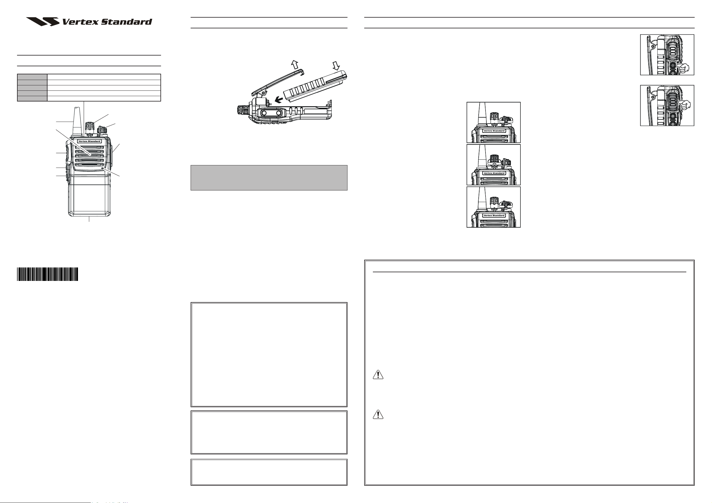
BATTERY PACK INSTALLATION AND REMOVAL
To install the battery, hold the transceiver with your left hand,
so your palm is over the speaker and your
thumb is on the top of the belt clip.
Insert the battery pack into the
battery compartment on
the back of the
Tilt the Belt Clip
radio while tilting the Belt
Clip outward,
then push the
bottom side of
Push the bottom side
of the battery pack
Insert the Battery Pack
PRELIMINARY STEPS
Install a charged battery pack onto the transceiver, as described
previously.
Screw the supplied antenna onto the Antenna jack. Never at-
tempt to operate this transceiver without an antenna connected.
If you have a Speaker/Microphone, we recommend that it not
be connected until you are familiar with the basic operation of
the VX-230.
OPERATION QUICK START
Turn the top panel’s VOL/PWR knob
clockwise to turn on the radio on.
the battery
pack until the battery pack locks with the Battery Pack Latch.
)
To remove the battery, turn the radio off and remove any pro-
tective cases. Slide the Battery Pack Latch on the bottom of the
radio, then slide the battery downward and out from the radio
while holding the Belt Clip.
Turn the top panel’s CH selector knob
to choose the desired operating channel.
Caution!
Do not attempt to open any of the rechargeable Lithium-Ion
packs, as they could explode if accidentally short-circuited.
Rotate the VOL/PWR knob to set the
LOW BATTERY INDICATION
As the battery discharges during use, the voltage gradually becomes
lower. When the battery voltage becomes to low, substitute a freshly
charged battery and recharge the depleted pack. When the battery
voltage is low, the LED indicator on the top of the radio will blink
red. Furthermore, if your Dealer sets the “Low Battery Alert” fea-
volume level. If no signal is present,
press and hold in the Programmable
key assigned to “SQL OFF” for more
than one second; background noise will
now be heard, and you may use this to
set the VOL/PWR knob for the desired audio level.
Press and hold in the Programmable
key assigned to “SQL OFF” for more
than one second (or press the key twice)
to quiet the noise and resume normal
(quiet) monitoring.
To transmit, monitor the channel and make sure it is clear.
To transmit, press and hold in the PTT
switch. Speak into the microphone area
of the front panel grille (lower righthand corner) in a normal voice level.
To return to the Receive mode, release
the PTT switch.
If a Speaker/Microphone is available, remove the plastic cap
and its two mounting screws from the right side of the transceiver, then insert the plug from the Speaker/Microphone into
the MIC/SP jack; secure the plug using the screws supplied
with the Speaker/Microphone. Hold the speaker grille up next
to your ear while receiving. To transmit, press the PTT switch
on the Speaker/Microphone, just as you would on the main
transceiver’s body.
Note:Save the original plastic cap and its mounting screws. They
should be re-installed when not using the Speaker/Microphone.
ture into the transceiver, an alert beeper will sound when the battery voltage is low.
Copyright 2008
VERTEX STANDARD CO., LTD.
EC085U100
VERTEX STANDARD CO., LTD.
4-8-8 Nakameguro, Meguro-Ku, Tokyo 153-8644, Japan
VERTEX STANDARD
US Headquarters
10900 Walker Street, Cypress, CA 90630, U.S.A.
YAESU EUROPE B.V.
P.O. Box 75525, 1118 ZN Schiphol, The Netherlands
YAESU UK LTD.
Unit 12, Sun Valley Business Park, Winnall Close
Winchester, Hampshire, SO23 0LB, U.K.
VERTEX STANDARD HK LTD.
Unit 5, 20/F., Seaview Centre, 139-141 Hoi Bun Road,
Kwun Tong, Kowloon, Hong Kong
VERTEX STANDARD (AUSTRALIA) PTY., LTD.
Normanby Business Park, Unit 14/45 Normanby Road
Notting Hill 3168, Victoria, Australia
All rights reserved.
No portion of this manual
may be reproduced
without the permission of
VERTEX STANDARD CO., LTD.
Printed in Japan
Important Notice for North American Users
Regarding 406 MHz Guard Band
The U.S. Coast Guard and National Oceanographic and Atmospheric Administration have requested the cooperation of the
U.S. Federal Communications Commission in preserving the
integrity of the protected frequency range 406.0 to 406.1 MHz,
which is reserved for use by distress beacons. Do not attempt
to program this apparatus, under any circumstances, for operation in the frequency range 406.0 - 406.1 MHz if the apparatus
is to be used in or near North America.
Warning - Frequency band 406 - 406.1 MHz is reserved for use
ONLY as a distress beacon by the US Coast Guard and NOAA.
Under no circumstance should this frequency band be part of
the preprogrammed operating frequencies of this radio.
Notice !
There are no owner-serviceable parts inside the transceiver.
All service jobs must be referred to an authorized VERTEX
STANDARD Service Representative. Consult your Authorized
VERTEX STANDARD Dealer for installation of optional accessories.
Part 15.21: Changes or modifications to this device not expressly approved by Vertex Standard could void the user’s authorization to operate this device.
SAFETY TRANING INFORMATIONSAFETY TRANING INFORMATION
SAFETY TRANING INFORMATION
SAFETY TRANING INFORMATIONSAFETY TRANING INFORMATION
This Radio has been tested and complies with the Federal Communications Commission (FCC) RF exposure limits for Occupational Use/
Controlled exposure environment. In addition, it complies with the
following Standards and Guidelines:
FCC 96-326, Guidelines for Evaluating the Environmental Effects
of Radio-Frequency Radiation.
FCC OET Bulletin 65 Edition 97-01 (1997) Supplement C, Evalu-
ating Compliance with FCC Guidelines for Human Exposure to
Radio Frequency Electromagnetic Fields.
ANSI/IEEE C95.1-1992, IEEE Standard for Safety Levels with
Respect to Human Exposure to Radio Frequency Electromagnetic
Fields, 3kHz to 300 GHz.
ANSI/IEEE C95.3-1992, IEEE Recommended Practice for the
Measurement of Potentially Hazardous Electromagnetic FieldsRF and Microwave.
WARNING: This radio generates RF electromagnetic energy
during transmit mode. This radio is designed for and classified
as Occupational Use Only, meaning it must be used only during the
course of employment by individuals aware of the hazards, and the
ways to minimize such hazards. This radio is not intended for use by
the General Population in an uncontrolled environment.
CAUTION: To ensure that your expose to RF electromagnetic
energy is within the FCC allowable limits for occupational use,
always adhere to the following guidelines:
This radio is NOT approved for use by the general population
in an uncontrolled environment. This radio is restricted to occupational use, work related operations only where the radio
operator must have the knowledge to control its RF exposure
conditions.
When transmitting, hold the radio in a vertical position with
its microphone 1 to 2 inches (2.5 to 5 cm) away from your
mouth and keep the antenna at least 1 inch (2.5cm) away from
your head and body.
The radio must be used with a maximum operating duty cycle
not exceeding 50 %, in typical Push-to-Talk (PTT) configurations. DO NOT transmit for more than 50 % of total radio use
time (50 % duty cycle). Transmitting more than 50 % of the
time can cause FCC RF exposure compliance requirements to
be exceeded.
The radio is transmitting when the red LED on the top of the
radio is illuminated. You can cause the radio to transmit by
pressing the PTT button or by using the VOX headset, model
VC-25.
DO NOT transmit when the radio is used in Body Worn con-
figuration with the following accessory: belt-clip (CLIP-18).
It must be used ONLY for (1) there is a 1.5 inch (4 cm) distance
from the body during transmitting, (2) monitoring purposes,
using the speaker only and (3) for carrying purposes.
Always use Vertex Standard authorized accessories.
The information listed above provides the user with the information
needed to make him or her aware of RF exposure, and what to do to
assure that this radio operates with the FCC RF exposure limits of this
radio.
Electromagnetic Interference/Compatibility
During transmissions, this radio generates RF energy that can
possibly cause interference with other devices or systems. To avoid
such interference, turn off the radio in areas where signs are posted
to do so.
Do not operate the transmitter in areas that are sensitive to electromagnetic radiation such as hospitals, health care facilities, aircraft, and blasting sites.
FCC LICENSE INFORMATION
This radio operates on communications frequencies which are subject to FCC (Federal Communications Commission) Rules and
Regulations. FCC Rules require that all operators using Private
Land Mobile radio frequencies obtain a radio license before operating their equipment.
 Loading...