

① ② ③
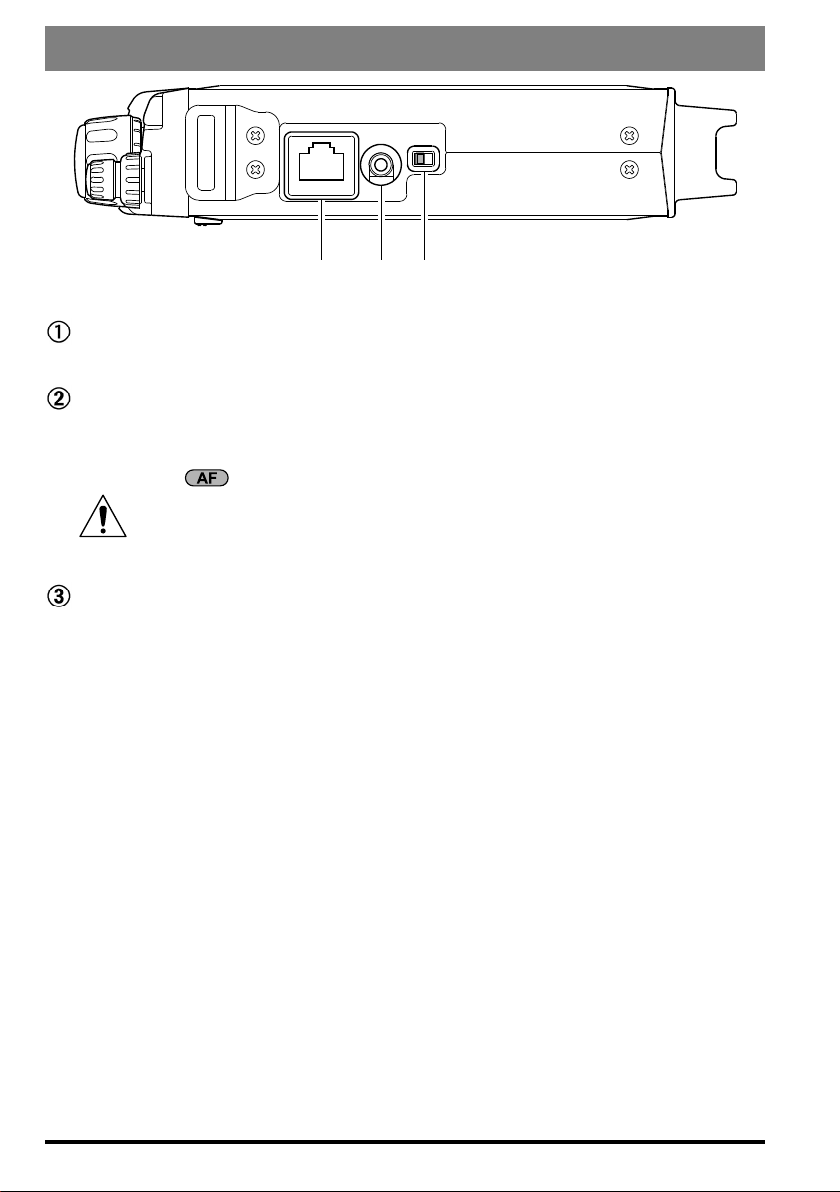
Side Panel Switch & Connectors
-
SP/PH SP PH
MIC
Jack
MIC
Connect the supplied
MH-31
A8J
Hand Microphone to this jack.
SP/PH
This 3.5-mm, 2-pin jack provides variable audio output for an external speaker (4 Ω 16 Ω impedance) or earphones. The audio level varies according to the setting of the
front panel’s knob.
prevent the possibility of injury to your ears.
SP-PH
If you use earphones with this transceiver, move this switch to the “PH” position before inserting the earphone plug into the
Jack
When you insert an earphone plug into this jack, the
(located to the right side of this jack) MUST BE set to the “PH” position, to
SP-PH
slide switch
Switch
SP/PH
Jack, to prevent injury your ears.
14 FT-818 Operating Manual
:
②
③
⑥
⑤④①
INPUT DC13.8V
GND
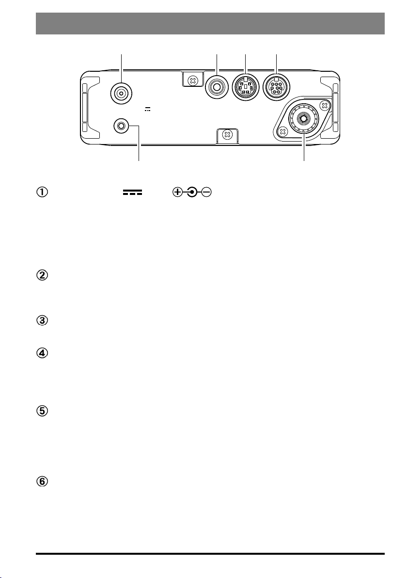
Rear Panel Connectors
ANT
KEY DATA ACC
INPUT:13.8V
This is the DC power supply connection for the transceiver, used when operating the
transceiver with an external power supply. Use the supplied DC cable to connect this
jack to the car battery or base station DC power supply, which must be capable of
supplying at least 3A @ 8 ~ 16 VDC. This jack is also used for battery charging (when
using the supplied
Terminal
GND
For best performance and safety, this Ground lug may be connected to a good earth
ground using a short, heavy, braided cable.
Jack
KEY
This 3.5-mm, 3-pin jack is used for connection to a CW keyer paddle or a straight key.
DATA
This 6-pin, mini-DIN jack accepts AFSK input from a Terminal Node Controller
(TNC); it also provides fixed-level Receiver Audio Output, Push-To-Talk (PTT),
Squelch Status, and ground lines.
ACC
This 8-pin, mini-DIN jack provides a closure to ground during transmission, ALC, a
transmitter-inhibit pin, and “band data” for connection to an external amplier. It is
also used for Transceiver-to Transceiver Cloning and for control of this transceiver
using a personal computer.
Jack
Jack
Jack
SBR-32MH
(
battery pack).
)
Jack
ANT
Connect your HF and/or 50 MHz antenna’s 50 Ω coaxial cable to this M-type (“SO239”) connector.
In its default setting, this jack does not function on 50/144/430 MHz bands. If you
want to enable this jack on 50/144/430 MHz bands, recall and change the settings of
Menu #07.
15FT-818 Operating Manual
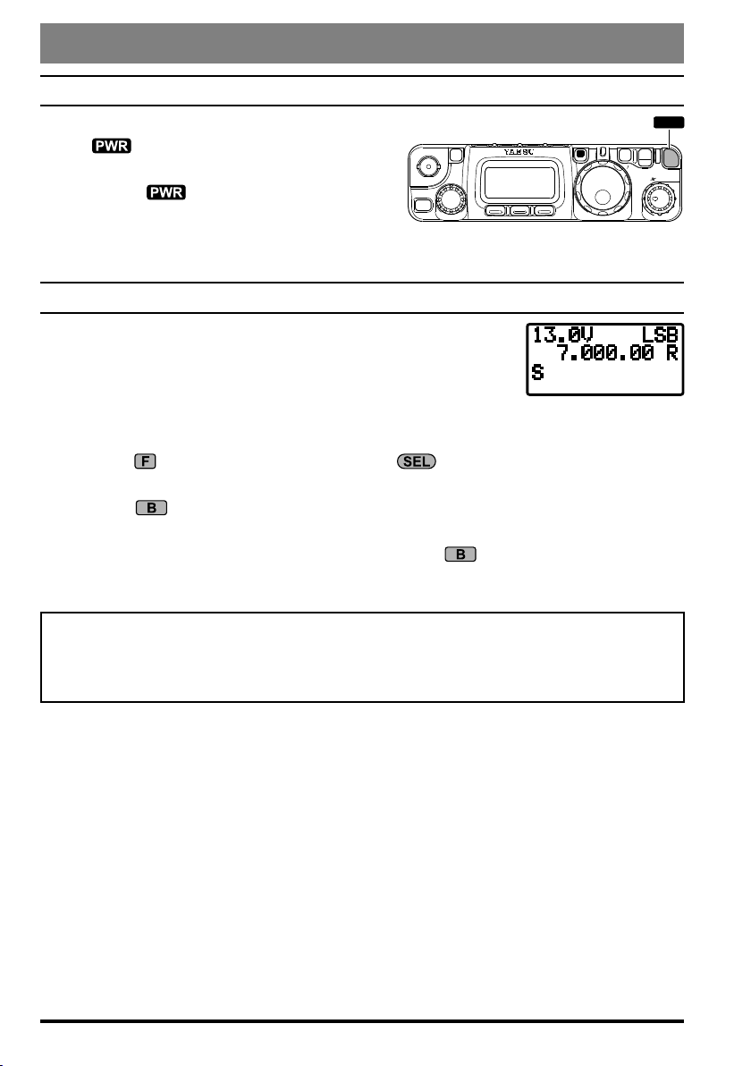
PWR
Operation
turning the tranSceiver On and OFF
1. To turn the transceiver on, press and hold in
the switch for one second.
2. To turn the transceiver off, again press and
hold in the switch for one second.
The one-second delay helps you avoid accidental
switching on (or off) of DC power.
SupplY vOltage diSplaY
When you turn on the transceiver, the DC supply voltage is indicated in the upper right corner of the LCD for two seconds. After
this interval, the display will resume its normal indication of the
operating mode (VFOa, VFOb, or Memory Channel Number).
To view the supply voltage at any time during operation:
HOME
E
L
S
CLAR
A B
F
V
M
LOCK
PWR
SQL/RF
F
A
C
1. Press the
Row 11*
2. Press the
key momentarily, then rotate the knob to select Operating Function
[
CHG, VLT, DSP
(
VLT
]
on the display.
)
key momentarily to display the supply voltage in the upper right
corner of the LCD.
(
3. To cancel the supply voltage display, again press the
VLT
)
key.
Remember, the Operating Row Number does not appear on the display.
If you have not operated your
FT-818
plug in the Battery Charger, and perform a 10 hour (use for
cycle, to ensure that the
SBR-32MH
within the past week, we recommend that you
PA-48B/C/U
is ready for operation when you are.
) charge
16 FT-818 Operating Manual
 Loading...