

Page 1

User’s manual
MENU
EX
I
T
ENT
FC 80
FC 90
Used with bait boat - Monitor bait boat battery; 300m RC distance
FC 80
FC 90
BAIT BOAT FISHFINDER
MENU
EXIT
ENT
www.goyachting.cn
Page 2

www.goyachting.cn
All right reserved! Except as expressly provided herein,
no part of this manual may be copied, reproduced, repub-
lished, transmitted or distributed for any purpose, without
prior written consent of Yachting Electronic Co., Ltd.
Yachting Electronic may find it necessary to change or end
our policies, regulations, and special offers at any time.
We reserve the right to change or improve its products and
to make changes in the content without obligation to notify
any person or organization.
For current updates or other information, please visit our
website:
www.goyachting.cn
Yachting Electronic Co., Ltd
Building107, No.508, Heyan Road,
Nanjing, 210038, China
Printed in China
Copyright 2008 Yachting Electronic Co., Ltd.
All rights reserved.
i
Page 3

Content
Introduction .................................................................1
Packing list...................................................................2
Using the product.........................................................4
Installing the battery.....................................................5
Install the RemoteEye to bait boat...............................6
Introduction of RemoteEye ....................................7
Tool list....................................................................8
RemoteEye installation method - 1.........................8
RemoteEye installation method - 2........................18
Operational Panel Basic..............................................24
Display.........................................................................25
Understanding the display.......................................25
Depth range.............................................................26
Content
Water surface line....................................................27
Operation.....................................................................29
Menu Operation Instruction...................................29
ii
Page 4

Sensitivity...............................................................31
Channel..................................................................32
Shallow...................................................................33
Depth Range...........................................................34
Fish ID....................................................................35
Units.......................................................................36
Backlight................................................................37
Contrast..................................................................38
Load DFT...............................................................39
Monitor SEL (FC90 Fishfinder only)....................40
BAT. Alarm (FC90 Fishfinder only)......................41
Language ...............................................................42
Trouble Shooting.........................................................43
Maintenance................................................................48
Guarantee Conditions..................................................49
Specifications and Features.........................................50
Specifications.........................................................50
Features..................................................................51
iii
Page 5

Introduction
FC80 / 90 is designe
d to be used with bait boat.
Introduction
Thank you for choosing our Fishfinders. and welcome
to the innovations of Yachting Electronic Co., Ltd! We has
been committed to fish finder R&D activities all the way
and its products have been reputed for their cutting-edge
technologies and reliable performance.
FC80 / 90 is designe
We offer 12months charge-free maintenance against any
damages induced by non-human factors; and damages
beyond the 12 months are handled with reasonable charges
based on concrete situations. For details regarding maint-
enance
To familiarize yourself better with the product’s operation
and maximize the utilization, we invite you to read the
User’s Guide carefully.
For any possible problems you may encounter during the
operation, please switch to the Trouble shooting section
service,
d to be used with bait boat
please refer to the warranty explanations.
for reference.
1
Page 6

Packing list
Packing list
Before you install the transducer to your bait boat, please
check the packing list below, and make sure you are not
missing any items.
1) A wireless remote sonar sensor
2) A control box
3) A antenna for mounting on bait boat
4) A power cable
5) A anenna-extended-cable
2
Page 7

6) A antenna for mounting on the sonar handheld(optional
Note:
RemoteEye
www.goyachting.cn.
for FC80; not inlcuded in FC90)
7) A sonar handheld with 3” FSTN LCD
8) A switch for On/Off controling of RemoteEye (optional)
The following items are also included:
a) two screws (mounting the transducer)
b) a battery buckle (when needed, being used to connect
power cable and 9v alkaline battery)
c) a copy of manual
Note:
the electric control & sonar system enclosed by the
dashed line are named RemoteEye
In the event that any of the items listed is found missing,
call us immediately or log on to our website at
.
www.goyachting.cn.
Clients located in other parts of the
to their respective local distributors.
world may also refer
Page 8

Using the product
Using the product
FC80 / 90 is designed to be used with bait boat. Properly
install the RemoteEye to your bait boat, power on the control
box
before you put the assemmed bait boat & RemoteEye
into the water, then you are ready to enjoy the operation.
Two ways of using the product
Page 9

Warning:
Installing the battery
Installing the battery
Warning:
with strength in the vertical direction!
do not split the battery cover
To take off the battery
cover, press it and
slide in the indicated
direction.
1. Turn the screw anti-clockwise with a screw driver.
Then slide the battery cover towards the bottom of the
unit and remove it from the main housing.
2. Install 4 “AAA” batteries. Be certain that the batteries
are aligned as per the diagram within the battery
compartment.
3. Slide the battery cover towards the top of the unit until
it is completely closed. Then turn the screw clockwise
Page 10

Install the RemoteEye to bait boat
Install the RemoteEye to bait boat
Note:
The picture below is a overall installation instrution showing
you the general conception to install the control & s
system(namely RemoteEye) to the bait boat, which is just
for your reference.
the selected bait boat here is just for your reference,
Note:
the installation way may vary according to the structure of
different bait boats.
onar
Page 11

Introduction of the RemoteEye
Introduction of the RemoteEye
Note:
RemoteEye indicates the whole set of electric & sonar
control system . It is used to be mounted on your bait
boat.
1. Control box
2. Wireless sensor
3. Antenna
4. Antenna-extended cable
5. Switch of on/off controlling for RemoteEye (optional)
6. Power cable
Note:
the antenna-extended cable is used to connect the
antenna and the control box. As sometimes you may have
to mount the antenna on your bait boat, instead of connect
Page 12

it directly to the control box. Thus it will be convenient
Tool List
Remo
teEye insta
llation method - 1
1. M
ake a supporting pla
te to hold the wireless sensor
Note:
for you to find enough space to place the control box at a
proper position.
Tool List
Hand drill
5/32” drill bits
Phillips and flat-head screwdriver
Marine sealant
Remo
1. M
The shape of supporting plate may be different according to
the shape of your bait boat.
Note:
(not included)
teEye insta
ake a supporting pla
the shape below is just for your reference.
llation method - 1
te to hold the wireless sensor
Page 13

2. Find a proper position and drill two holes on the top
2. Find a proper position and drill two holes on the top
cover of your bait boat, as figured below:
Note:
cover of your bait boat, as figured below:
Note:
The hole is used to be through the sensor cable, the
diameter should be about 11.5mm
The hole is used to mount the antenna, the diameter
should be about 5.8mm.
Page 14

3. Monut the antenna on the top cover of your bait boat.
3. Monut the antenna on the top cover of your bait boat.
3. Monut the antenna on the top cover of your bait boat.
a) mount the antenna-extended cable to the top cover
There are two connector of the antenna-extended cable, one
is used to connetct to the antenna, another is used to connect
to the control box.
Firstly, take out the screw from the antenna-extended
cable, then hold one end of the cable through the hull of
bait boat(as instructed below). Finallly, tighten the screw.
connect to antenna
connect to control box
3. Monut the antenna on the top cover of your bait boat.
a) mount the antenna-extended cable to the top cover
a) mount the antenna-extended cable to the top cover
There are two connector of the antenna-extended cable, one
There are two connector of the antenna-extended cable, one
is used to connetct to the antenna, another is used to connect
is used to connetct to the antenna, another is used to connect
to the control box.
to the control box.
connect to control box
connect to control box
connect to antenna
connect to antenna
Firstly, take out the screw from the antenna-extended
Firstly, take out the screw from the antenna-extended
cable, then hold one end of the cable through the hull of
cable, then hold one end of the cable through the hull of
bait boat(as instructed below). Finallly, tighten the screw.
bait boat(as instructed below). Finallly, tighten the screw.
hull of bait boat
screw
Page 15

b) screw the antenna to the antenna-extended cable.
b) screw the antenna to the antenna-extended cable.
b) screw the antenna to the antenna-extended cable.
Page 16

4. Mount the wireless sensor on the supporting plateas
Note:
4. Mount the wireless sensor on the supporting plateas
instructed below,
a) drill three holes on the supporting plate.
Diameter of hole-1 is about 12.5mm
Diameter of hole-2 and hole-3 is about 3.5mm
Note: use a pencil to mark the position before drilling the
hole-2 and hole-3.
screw
4. Mount the wireless sensor on the supporting plateas
instructed below,
instructed below,
a) drill three holes on the supporting plate.
a) drill three holes on the supporting plate.
Diameter of hole-1 is about 12.5mm
Diameter of hole-1 is about 12.5mm
Diameter of hole-2 and hole-3 is about 3.5mm
Diameter of hole-2 and hole-3 is about 3.5mm
Note: use a pencil to mark the position before drilling the
Note:
use a pencil to mark the position before drilling the
hole-2 and hole-3.
hole-2 and hole-3.
screw
screw
Page 17

5. Mount supporting plate on the top cover of bait boat.
5. Mount
supporting plate
on the top cover of bait boat.
6. Find a proper position and place the control box into
the bottom cover of your bait boat.
5. Mount supporting plate on the top cover of bait boat.
Drill 4 holes on the supporting plate, and tighten the supporting plate on the top cover of your bait boat by screws.
6. Find a proper position and place the control box into
the bottom cover of your bait boat.
5. Mount
Drill 4 holes on the supporting plate, and tighten the supp-
Drill 4 holes on the supporting plate, and tighten the supp-
orting plate on the top cover of your bait boat by screws.
orting plate on the top cover of your bait boat by screws.
supporting plate
on the top cover of bait boat.
6. Find a proper position and place the control box into
6. Find a proper position and place the control box into
the bottom cover of your bait boat.
the bottom cover of your bait boat.
Page 18

find a proper position
Note:
7. Connect the antenna-extended cable to the control box.
Note: It could be better to find a way to fix the control box
in the bottom cover of your bait boat. As when used with
your bait boat in the water, the control box may wobble
with the shave, which may damage the inner electronic
parts.
7. Connect the antenna-extended cable to the control box.
find a proper position
find a proper position
Note: It could be better to find a way to fix the control box
Note:
It could be better to find a way to fix the control box
in the bottom cover of your bait boat. As when used with
in the bottom cover of your bait boat. As when used with
your bait boat in the water, the control box may wobble
your bait boat in the water, the control box may wobble
with the shave, which may damage the inner electronic
with the shave, which may damage the inner electronic
parts.
parts.
7. Connect the antenna-extended cable to the control box.
7. Connect the antenna-extended cable to the control box.
Page 19
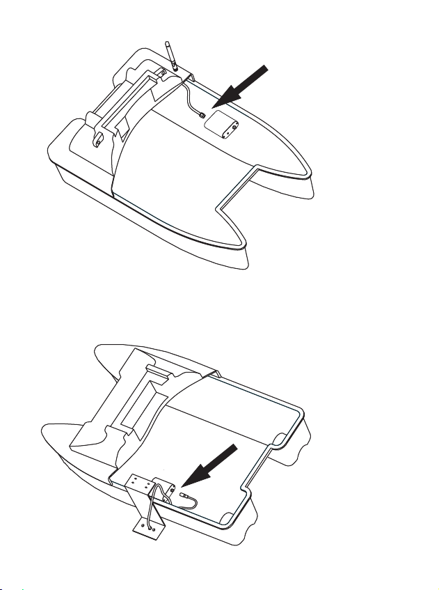
8. Connect the wireless sensor to the control box.
8. Connect the wireless sensor to the control box.
8. Connect the wireless sensor to the control box.
8. Connect the wireless sensor to the control box.
Page 20
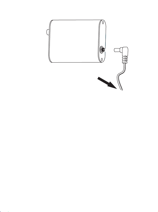
9. connect the control box to the battery.
connect the control box to the battery.
a) for FC80
Warning:
b) for FC90
Note:
Note:
9. connect the control box to the battery.
a) for FC80
Warning: we strongly suggest you using a 9v alkaline battery,
instead of using the bait boat battery for powering, otherwise
thus short Remote Control distance and abnormal display
may occur due to the interference caused by bait boat battery.
b) for FC90
Both bait boat battery and 9v alkaline battery can be used for
power supply, without any interference.
Note: correctly connect the control box to the bait boat
battery, then you can monitor the remained voltage of your
bait boat all the time. Avoiding using under a low battery.
Note: the range of battery monitoring is 5.2~15v.
connect to the battery
9. connect the control box to the battery.
connect to the battery
connect to the battery
a) for FC80
a) for FC80
Warning: we strongly suggest you using a 9v alkaline battery,
Warning:
instead of using the bait boat battery for powering, otherwise
instead of using the bait boat battery for powering, otherwise
thus short Remote Control distance and abnormal display
thus short Remote Control distance and abnormal display
may occur due to the interference caused by bait boat battery.
may occur due to the interference caused by bait boat battery.
b) for FC90
b) for FC90
Both bait boat battery and 9v alkaline battery can be used for
Both bait boat battery and 9v alkaline battery can be used for
power supply, without any interference.
power supply, without any interference.
Note: correctly connect the control box to the bait boat
Note:
battery, then you can monitor the remained voltage of your
battery, then you can monitor the remained voltage of your
bait boat all the time. Avoiding using under a low battery.
bait boat all the time. Avoiding using under a low battery.
Note: the range of battery monitoring is 5.2~15v.
Note:
we strongly suggest you using a 9v alkaline battery,
correctly connect the control box to the bait boat
the range of battery monitoring is 5.2~15v.
Page 21
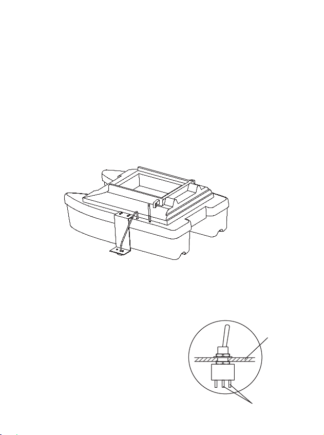
Warnning: be careful not reversing connection of positive
Warnning:
10. assemble the bait boat.
Note:
Warnning: be careful not reversing connection of positive
and negative pole to the bait boat battery. (black wire is
for negative pole; black & white wire is for positive pole)
10. assemble the bait boat.
With the above steps were finished, carefully assemble your
bait boat, then the complete set of bait boat & wireless fish
finder is ready to use.
Note: sometimes you may need a switch to control on/off
of the RemoteEye (see the “packing list-page2”).
1). Drill a hole on your bait boat
housing, tighten the switch
on the bait boat.
2). connect the switch to the
power cable.
conect to
power cable
hull of
bait boat
Warnning:
and negative pole to the bait boat battery. (black wire is
and negative pole to the bait boat battery. (black wire is
for negative pole; black & white wire is for positive pole)
for negative pole; black & white wire is for positive pole)
10. assemble the bait boat.
10. assemble the bait boat.
With the above steps were finished, carefully assemble your
With the above steps were finished, carefully assemble your
bait boat, then the complete set of bait boat & wireless fish
bait boat, then the complete set of bait boat & wireless fish
finder is ready to use.
finder is ready to use.
Note: sometimes you may need a switch to control on/off
Note:
of the RemoteEye (see the “packing list-page2”).
of the RemoteEye (see the “packing list-page2”).
1). Drill a hole on your bait boat
1). Drill a hole on your bait boat
housing, tighten the switch
housing, tighten the switch
be careful not reversing connection of positive
sometimes you may need a switch to control on/off
hull of
hull of
bait boat
bait boat
on the bait boat.
on the bait boat.
2). connect the switch to the
2). connect the switch to the
power cable.
power cable.
conect to
conect to
power cable
power cable
Page 22

Remo
Remo
teEye insta
llation method - 2
Note:
RemoteEye installation method - 2
As the structure of bait boats is different, sometimes
maybe you prefer mounting the sensor to your bait boat in
other method, see the following example:
Note: for such installation method, finding a proper
mounting location for the sensor is very important. Otherwise
an unproper
mounting position may cause a short Remote
Control distance or abnormal display on the screen.
Mounting the sensor
on the bottom hull of the bait boat
RemoteEye installation method - 2
teEye insta
As the structure of bait boats is different, sometimes
As the structure of bait boats is different, sometimes
maybe you prefer mounting the sensor to your bait boat in
maybe you prefer mounting the sensor to your bait boat in
other method, see the following example:
other method, see the following example:
Mounting the sensor
Mounting the sensor
on the bottom hull of the bait boat
on the bottom hull of the bait boat
llation method - 2
Note: for such installation method, finding a proper
Note:
for such installation method, finding a proper
mounting location for the sensor is very important. Otherwise
mounting location for the sensor is very important. Otherwise
an unproper
an unproper
Control distance or abnormal display on the screen.
Control distance or abnormal display on the screen.
mounting position may cause a short Remote
mounting position may cause a short Remote
Page 23

Sonar working method
Sonar working method
Sonar working method
When sonar works, the signals were remited in the direct-
ion as instructed below:
So, in the area A and area B, there should be no any
obstacle, otherwise the sonar signals will be “blocked”,
thus sonar unit will not be able to receive the signal normally,
which will cause short Remote Control distance, or abnormal
display on the screen.
For example, in the following sensor mounting figure,
A is right; B is wrong;
A
B
Sonar working method
When sonar works, the signals were remited in the direct-
When sonar works, the signals were remited in the direct-
ion as instructed below:
ion as instructed below:
A
A
So, in the area A and area B, there should be no any
So, in the area A and area B, there should be no any
obstacle, otherwise the sonar signals will be “blocked”,
obstacle, otherwise the sonar signals will be “blocked”,
thus sonar unit will not be able to receive the signal normally,
thus sonar unit will not be able to receive the signal normally,
which will cause short Remote Control distance, or abnormal
which will cause short Remote Control distance, or abnormal
display on the screen.
display on the screen.
B
B
For example, in the following sensor mounting figure,
For example, in the following sensor mounting figure,
A is right; B is wrong;
A is right; B is wrong;
Page 24

B
a) In the A mounting position, the sonar signals can be
remitted without any obstacle in the two direction;
b) In the B mounting position, the sonar signals can not
be remitted normally, as they are blocked by the hull of
the bait boat;
hull of boat
A
B
B
A
A
hull of boat
hull of boat
a) In the A mounting position, the sonar signals can be
a) In the A mounting position, the sonar signals can be
remitted without any obstacle in the two direction;
remitted without any obstacle in the two direction;
b) In the B mounting position, the sonar signals can not
b) In the B mounting position, the sonar signals can not
be remitted normally, as they are blocked by the hull of
be remitted normally, as they are blocked by the hull of
the bait boat;
the bait boat;
Page 25
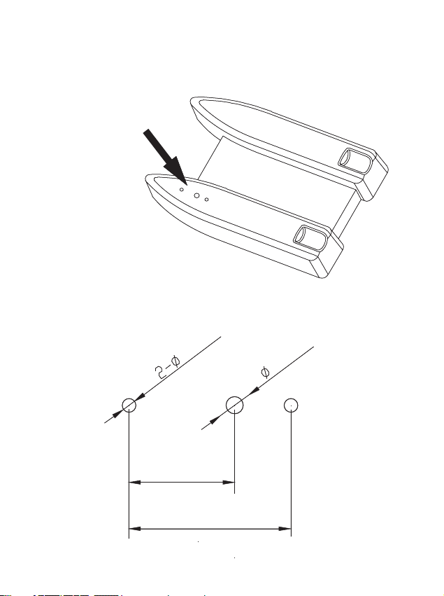
1. Find a proper mounting position, and drill 3 holes on
1. Find a proper mounting position, and drill 3 holes on
the bottom of your bait boat
Note:
1. Find a proper mounting position, and drill 3 holes on
the bottom of your bait boat
Note: the 3 holes should be drilled with the following
dimension:
3 holes
41.6 mm
27.1 mm
12.0 mm
3.0 mm
1. Find a proper mounting position, and drill 3 holes on
the bottom of your bait boat
the bottom of your bait boat
3 holes
3 holes
Note: the 3 holes should be drilled with the following
Note:
the 3 holes should be drilled with the following
dimension:
dimension:
3.0 mm
3.0 mm
12.0 mm
12.0 mm
27.1 mm
27.1 mm
41.6 mm
41.6 mm
Page 26
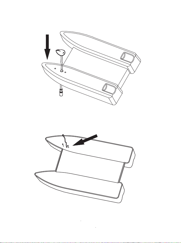
2. Hold the sensor calbe through the 12mm-hole
2. Hold the sensor calbe through the 12mm-hole
3. Fix the sensor with 2 screws
Note:
2. Hold the sensor calbe through the 12mm-hole
3. Fix the sensor with 2 screws
Note: please spread some sealed glue on the screws before
fixing the sensor.
2. Hold the sensor calbe through the 12mm-hole
3. Fix the sensor with 2 screws
3. Fix the sensor with 2 screws
Note: please spread some sealed glue on the screws before
Note:
please spread some sealed glue on the screws before
fixing the sensor.
fixing the sensor.
Page 27
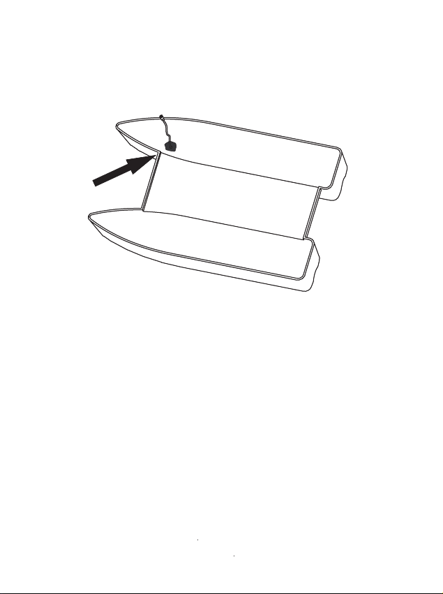
4. Spread some sealed glue to the drilled location,
4. Spread some sealed glue to the drilled location,
preventing water leakage happening
5. Carry out the following steps same with step 6~10
instructed in “RemoteEye installatiion method -1”
4. Spread some sealed glue to the drilled location,
preventing water leakage happening
5. Carry out the following steps same with step 6~10
instructed in “RemoteEye installatiion method -1”
4. Spread some sealed glue to the drilled location,
preventing water leakage happening
preventing water leakage happening
5. Carry out the following steps same with step 6~10
5. Carry out the following steps same with step 6~10
instructed in “RemoteEye installatiion method -1”
instructed in “RemoteEye installatiion method -1”
Page 28
Operational Panel Basic
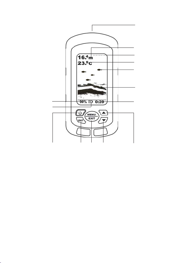
Operational Panel Basic
(1) Transducer plug
(For NAKI8850B model)
(2) Depth Reading
(3) Water surface line
(4) -Temperature Reading
-Voltage Reading
(FC90 only)
(5) Fish Icon
(6) Bottom
(7) Depth Range
(8) Sensitivity Reading
(9) Battery Strength
(10) Power Key
(11) Ent Key
(12) Menu and Exit Key
(13) Down Arrow Key.
(14) Up Arrow Key
Page 29
Display
Display
1. Understand
ing th
e display
1. Understand
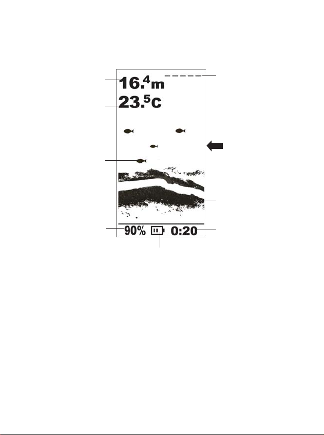
Depth reading
-Temperature reading
-Voltage reading of
bait boat battery
(FC90 only)
ing th
Fish icon
Sensitivity
e display
Handheld battery strength
Water surface
line
Sonar information
scroll from right to
left
Bottom
Depth range
(1) Depth reading: indicate water depth
(2) Temperature reading: indicate air or water temperature
Voltage reading: indicate the voltage of bait boat battery
(3) Sensitivity: the curren sensitivity setting
(4)
Water surface line: display the position of water surface
(5) Fish icon: a fish symbol to display the detected target
(6) Bottom: indicate the bottom condition
Page 30

(7) Depth range: the current Depth range setting
2. D
epth range
(8)
Battery strength: indicate the remained handheld battery
strength
The detection graph is shown from the right corner from
top to down. It would scroll forwards to left continuously.
The most present and newest signals are displayed on the
rightmost screen.
2. D
epth rang
The unit will automatically adjust the depth range according
to water conditions. It always keeps the bottom displayed
in the lower portion of the screen.
When the depth unit is set to feet, this fish finder has the
following depth ranges: 10, 15, 30, 50, 60, 80, 100
and feet.
When the depth unit is set to meter, the fish finder has the
following depth ranges: 3, 5, 10, 15, 20, 25, 30, 35, and 40m.
Depth range changes or signal loss will cause lines with
missing detail and / or abrupt changes in the graphed bottom.
The screen image jump shown here is due to an automatic
Page 31
change in depth.
3. Water surface line
New returns graphed at a different scale will not match up
with the historic data already graphed at a higher or lower
scale.
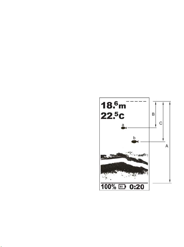
3. Water surface line
The water surface line indicate the displayed position of
water surface on the screen, which is very helpful for you
to estimate the depth of
detected fish.
For example,
the current depth reading
is 18m, and the position
of fish-a icon(B) is about
1/3 of total depth( A), thus
the 1-fish lies on the position
about (18.6*1/3=)6.2m deep
from water surface.
Accordingly, you could estimate the
the A total depth, which is (18.6*1/2=)9.3m.
fish-b lies about 1/2 of
Page 32

Underwater conditions vary greatly, so some experience
is
needed to get the most benefits of FC80 / 90.
Use the message
for your judgment,
of FC80 / 90.
displayed in the screen as a helpful tools
thus you could exert the full function
Page 33
Operation
Operation
Menu O
peration Instr
uction
Note:
Note:
Menu O
The menu setting is convenient and friendly.
You can get various function setting by simple operation.
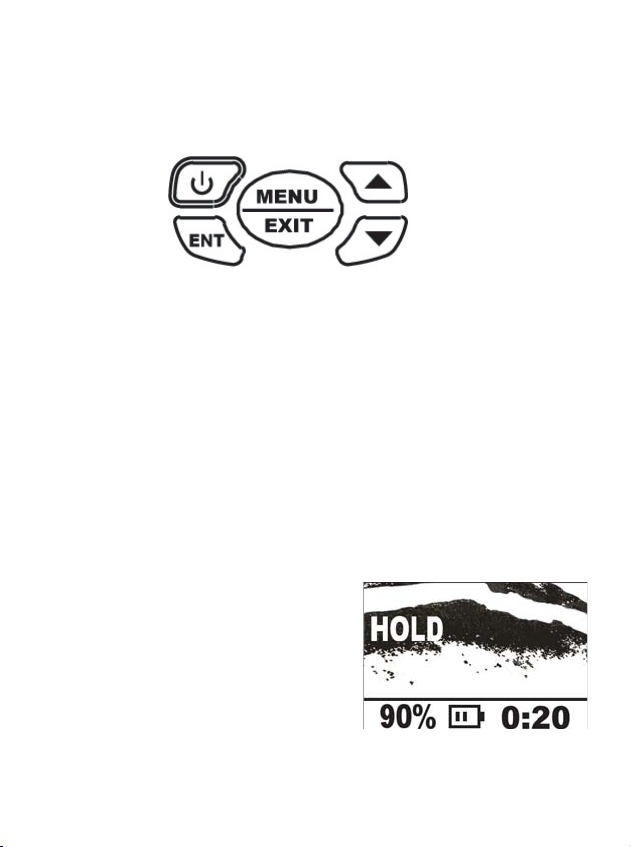
1. Power key: Power on / Power off
Note:
for 3s, then release it.
2. Ent key: To confirm a setting / hold the screen.
Note:
working, pressing Ent key will
“freeze” the screen, which is
peration Instr
to shut off the unit, press the Power key and keep it
when the unit is
uction
helpful for you to carefully
study the underwater condition.
Page 34
Note:
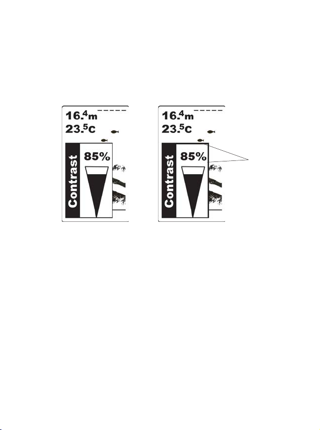
when you enter into a menu setting, pressing Ent
Note:
key, then you are able to change the setting and the frame
line of current menu will look thicker then non-setting. see
following:
thicker
non-setting
setting
To exit the setting condition, press ENT key again.
3. MENU & EXIT key: to enter or exit menu setting.
4. Up arrow / down arrow key: to increase / decrease the
setting value.
Page 35
Sensitivity
Sensitivity
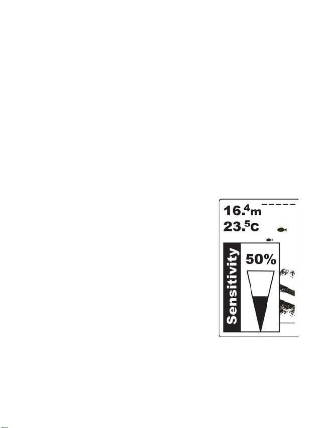
Sensitivity determines how echoes will be displayed on the
screen.
Increasing the sensitivity will make you see more details
on the screen. In such situations when you see too much
clutter on the screen, decreasing the sensitivity will play
an effect. The larger the sensitivity is, the more relatively
strong sonar returns the screen will display. If the sensitivity
is decreased too low, most sonar returns (which maybe fish)
will not be displayed.
In situation while water is clear or very
deep, try increasing
which will let you see even the very
weak returns.
However in situation while water is
turbid, try decreasing the sensitivity,
which will make only the useful echo
be showed on the screen and the noise will be omitted.
To set the Sensitivity:
the sensitivity,
Page 36
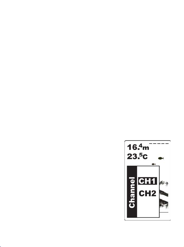
1) Press MENU to enter into menu setting,
Channel
CH1
- for FC
80 / 90
CH2 - for NAKI8850B
2) Use the Up / Down Arrow to select Sensitivity option.
3) Press ENT to confirm selecting
Use the Up / Down Arrow to increase / decrease the
4)
value
5) Press ENT to confirm the setting.
6) Press EXIT to exit.
Channel
Channel make it possible for you to switch using between
the wireless model and another wire model NAKI8850B
(provided that you have bought one).
CH1
- for FC
CH2 - for NAKI8850B
To set the Channel
1) Press MENU to enter into menu
80 / 90
setting,
2) Use the Up / Down Arrow to
select Channel option.
3) Press ENT to confirm selecting
32
Page 37
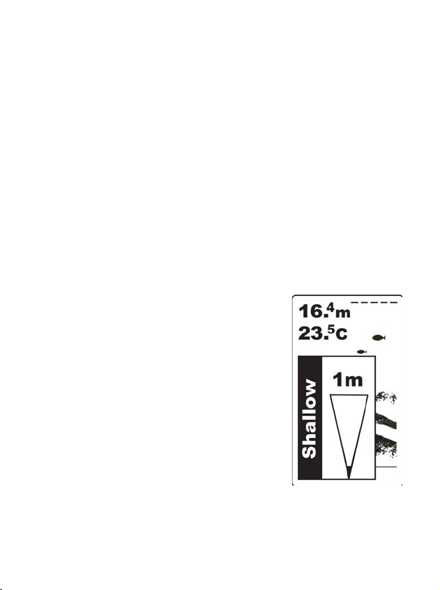
Use the Up / Down Arrow to change the
Shallow
4)
5) Press ENT to confirm the setting.
6) Press EXIT to exit.
Shallo
value
The Fishfinder sound an alarm tone when the bottom goes
shallower or equal than the alarm’s setting.
You also could exit alarm mode by enter into Shallow menu
and artificially increase the current depth alarm value to a
safe grade.
To set the Shallow:
1) Press MENU to enter into
menu setting,
2) Use the Up / Down Arrow to
select Shallow option.
3) Press ENT to confirm selecting
4) Use the Up / Down Arrow to
increase / decrease the value
5) Press ENT to confirm the setting.
6) Press EXIT to exit.
33
Page 38

Depth Range
Depth Range
Depth Range determine in which portion the bottom will
display in the screen. (For example, if the actual depth is
10m, and the current Depth Range is 20m, then the bottom
will display on 50% portion of the screen).
To set the Depth Range:
1) Press MENU to enter into menu
setting,
2) Use the Up / Down Arrow to
select Depth Range option.
3) Press ENT to confirm selecting
4) Use the Up / Down Arrow to
change the value
5) Press ENT to confirm the setting.
6) Press EXIT to exit.
34
Page 39
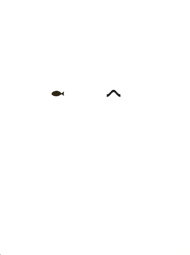
Fish ID.
Fish ID.
Note:
Fish ID control the way the detected target is displayed on
the screen.
1) If Fish ID is on, a fish icon will be displayed when some
fish and other object is detected.
2) If Fish ID is off, a arch will be displayed on the screen.
Fish ID is On
Note:
your sonar unit is advanced, however it can not
Fish ID is Off
distinguish between fish and other suspended objects such
as turtles, trotlines, submerged floats, air bubbles, etc. One
word, it could be fooled. So, you may see fish icon on the
screen, actually there is no fish underwater.
However, the Fish ID is very helpful for you to take some
of the work out of studying the screen. That means Fish ID
provides you a tool to distinguish the fish in a max possibility
and omits other negligible sonar information.
To know as more as possible what’s under your boat, we
35
Page 40
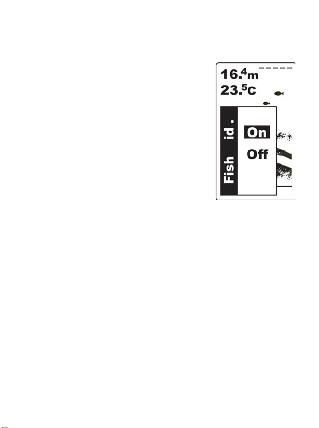
suggest you turn off the Fish ID, and only study the sonar
.
Units
returns which is displayed as archs.
To set the Fish ID.:
1) Press MENU to enter into menu
setting,
2) Use the Up / Down Arrow to
select Fish ID.
3) Press ENT to confirm selecting
4) Use the Up / Down Arrow to
change the value.
5) Press ENT to confirm the setting.
6) Press EXIT to exit.
Units
Units is used to choose depth unit and Temp unit. There
are four combinations for you to choose the depth unit and
Temp unit:
Fahrenheit / Feet
Fahrenheit / Meter
Celsius / Feet
Celsius / Meter
option.
36
Page 41

To set the Units.
.
Back
light
1) Press MENU to enter into menu
setting,
2) Use the Up / Down Arrow to
select Units. option.
3) Press ENT to confirm selecting
4) Use the Up / Down Arrow to
change the value.
5) Press ENT to confirm the setting.
6) Press EXIT to exit.
Back
ligh
Backlight is used to let you choose whether the backlight
is on or auto in some enviroment.
To set the Backlight:
1) Press MENU to enter into menu
setting,
:
2) Use the Up / Down Arrow to
select Backlight option.
3) Press ENT to confirm selecting
37
Page 42
4) Use the Up / Down Arrow to change the value.
Contrast
Contrastst
Contrast
5) Press ENT to confirm the setting.
6) Press EXIT to exit.
Contrast
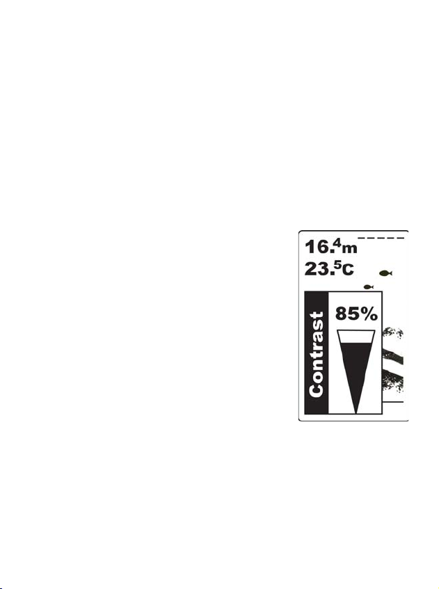
Contrast is used to let you get a most suitable display when
you operate the unit.
To set the Contra
1) Press MENU to enter into menu
setting,
2) Use the Up / Down Arrow to
select Contrast
3) Press ENT to confirm selecting
4) Use the Up / Down Arrow to
increase / decrease the value.
5) Press ENT to confirm the setting.
6) Press EXIT to exit.
:
option.
38
Page 43
Loa
Loa
d DFTFT
Load
DFT
Load DFT
d D
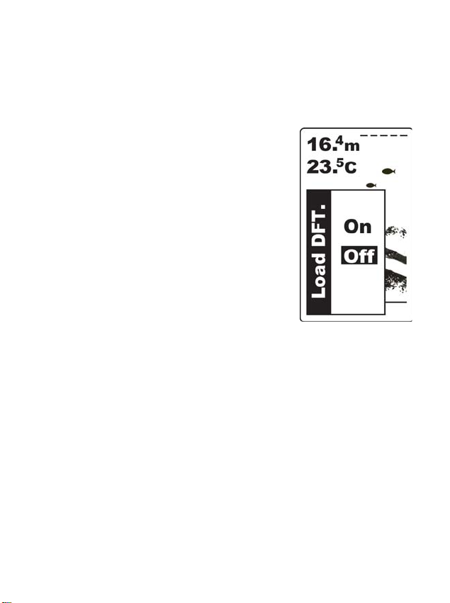
Load DFT is used to restore to the factory settings.
To set the Load
1) Press MENU to enter into menu
setting,
2) Use the Up / Down Arrow to
select Load DFT
3) Press ENT to confirm selecting
4) Use the Up / Down Arrow to
change the option.
5) Press ENT to confirm the setting.
6) Press EXIT to exit.
DFT
:
option.
39
Page 44
Monitor SEL
Monitor SEL
Monitor SEL
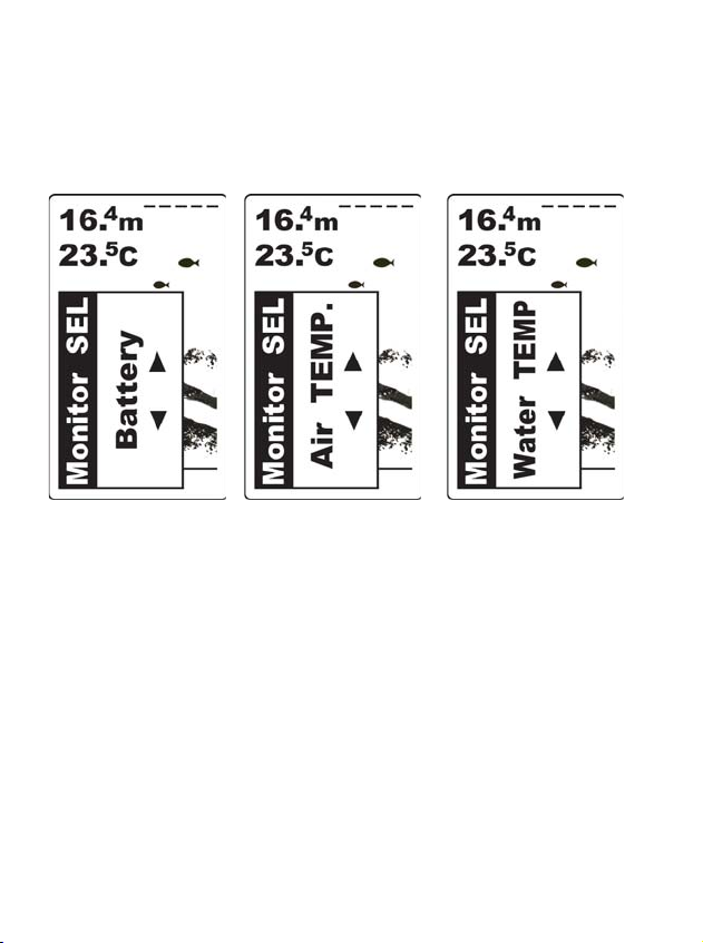
Monitor SEL is used to detect the remained voltage of
the bait boat and Water or Air temperature.
Battery Air Temp. Water Temp.
(FC90 Fishfinder only)
To set the Monitor SEL
1) Press MENU to enter into menu setting,
2) Use the Up / Down Arrow to select Monitor SEL option.
3) Press ENT to confirm selecting
4) Use the Up / Down Arrow to change the option.
5) Press ENT to confirm the setting.
6) Press EXIT to exit.
:
40
Page 45

BAT. Alarm
BAT. Alarm
When the bait boat battery is lower then the voltage
setting, the FC90 fishfinder will
sound an alarm tone and a
warning message will appear on the screen.
Set a warning value for battery alarming, and when the
alarm tone appears, run your bait boat back as soon as
possible.
You also could exit alarm mode by enter into BAT.Alarm
menu and artificially increase the setting to a safe value.
To set the BAT. Alarm:
1) Press MENU to enter into menu
setting,
2) Use the Up / Down Arrow to
select BAT. Alarm option.
(FC90 Fishfinder only)
3) Press ENT to confirm selecting
4) Use the Up / Down Arrow to
change the value.
5) Press ENT to confirm the setting.
6) Press EXIT to exit.
41
Page 46

Language
Language
You can choose different language for the menu operation:
English
German
French
Russian
To set the Language:
1) Press MENU to enter into menu
setting,
2) Use the Up / Down Arrow to
select Language option.
3) Press ENT to confirm selecting
4) Use the Up / Down Arrow to
change the option.
5) Press ENT to confirm the setting.
6) Press EXIT to exit.
42
Page 47

Trouble shooting
Trouble shooting
You are not supposed to fix the handheld or the sensor.
The product contains no customizable parts. On the other
hand, the waterproof performance is enabled by unique
techniques, functions of which may be disabled by unau-
thorized disassembly. On this account, only professional
maintenance personnel properly authorized by the Company
are entitled to any repair necessary.
We have been contacted frequently by our customers req-
uesting repair service. We inspect their products and find
many of them are not in need of repair: the problems occur
because some customers are not very acquainted with
product usage. And we are forced to label these products
as “inapplicable for maintenance” and return them to the
customers. Therefore, in the event of problems during
product use, we invite you to read the following trouble-
shooting part carefully before you send the product for
maintenance.
43
Page 48

1.No signal on screen
1.No signal on screen
If the fishfinder fails to receive signals from the sensor, it
will stop updating the screen (which will then remain
unchanged). Under any circumstances, if the handheld
can not receive signals transmitted by the sensor or the
sensor is out water for several seconds, the screen will
seem the same until the sensor is placed in water again
and signals are restored.
1) FC80/90 is a product depending upon line of sight.
Obstacles between the handheld and the sensor can con-
tribute to signal loss.
2) FC80/90 has a detection depth ranging from 1 to 100
feet (0.3~30m). Incorrect readings may appear in water
areas with depth less than 0.3m. Additionally, consider-
ing the sonar physical characters, we suggest you avoid
using the product in swimming pools or small-sized
enclosed water areas.
3) The maximum remote-control distance for the sensor
reaches 1000 feet (300m). If the sensor with the bait boat
44
Page 49

moves out
2.
Nothi
ng is disp
layed after the handheld’s power is
switched on.
3.
When using the device in shallow water areas, the screen
does not display things normally and depths are not
indicated with consistency.
4.
The picture displa
yed on the sc
reen vibrates and the sea
bed contour has abrupt changes.
signals will be transmitted to the handheld.
Nothi
2.
switched on
Be sure the battery's positive and negative poles are corr-
ectly oriented in the holder. Also, check if the battery has
enough capacity.
3.
When using the device in shallow water areas, the screen
does not display things normally and depths are not
indicated with consistency.
The sensor has a perfect performance in water from
4 to 100 feet (1.2~30m) deep. Abnormal display and
inconsistent depths may occur when used in areas with
depth less than 1.2m. Try to use it in deeper waters.
of the range, inconsistent signals or even no
ng is disp
layed after the handheld’s power is
4.
The picture displa
bed contour has abrupt changes.
The picture vibrates because the sea bottom depth being
scanned is changing. Since the depth range used by the
yed on the sc
45
reen vibrates and the sea
Page 50

current test signal and by the previous test signal differs,
5. Nothi
ng appears
on the display even you can see fish
under the sensor.
6. The dis
play becom
e so cluttered that you even could
not achieve a clear bottom
plus the varying height of the sea bed contour, pictures
displayed on the screen will occupy different heights,
causing the vibrating phenomenon.
5. Nothi
under the sensor.
surface of the transducer might help.
b) Electrical noise nearby can interfere with the sonar,
which will cause some weaker signals being elimin-
ated.
6. The dis
not achieve a clear bottom
Such cluttered display maybe caused because:
a) The water is too low
b) The water is too turbid
c) There are so much debris in the water,
ng appears
a) Oil, dirt and fuel might cause a film to form on the
sensor and reduce its effectiveness. Cleaning the
play becom
on the display even you can see fish
e so cluttered that you even could
46
Page 51

7. The sonar unit can not reach 300m. There is a abnormal
7. The sonar unit can not reach 300m. There is a abnormal
display on the display, and when the bait boat is about
60~70m far away, the sonar unit stop working.
display on the display, and when the bait boat is about
60~70m far away, the sonar unit stop working.
a) Please confirm the sensor is mounted at the proper
location on your bait boat. A improper mounting location
will cause abnormal display.
b) Please check whether you are using the bait boat batt-
ery for power suppling. For FC80, we strongly suggest
you connecting
battery, not connecting it to your bait boat battery.
abnormal display may occur. For FC90, both is accepted.
c) Please check the RemoteEye installation, and confirm
the antenna mounted on your bait boat is correctly
connected to the control box through the antenna-extended
cable.
d) The radio performance is easily effected by cloudy or
rainy day, which will cause the Remote Control distance
decreasing greatly.
the RemoteEye to a separate 9v Alkaline
Otherwise
47
Page 52

Maintenance
Maintenance
1. For the case
2. F
or the screen
With a view to making use of your Fishfinder, we reco-
mmend you follow the steps below and carry out maint-
enance.
1. For the case
Cleaning the sonar unit’s outer case (except for the screen)
with a cloth dipped mild detergent solution, and then wipes
it dry.
2. F
or the screen
Use a piece of soft cloth or pelt to clean the screen (fresh
water or eyeglass cleaner can be used if needed). Stubborn
dirt or oil stains remaining on the screen shall not be wiped
with force; otherwise it may scratch the surface.
Additionally, give daily attention to ensure the screen is
keep away from any chemicals.
48
Page 53

Guarantee Conditions
Guarantee Conditions
1.
We assure you this product is free from defects in materials
and workmanship. The warranty coverage is One Year from
the date of purchase, during which if the unit fails to perform
as described in the product’s written specifications, we will
repair or replace it free of charge. As for products exceeding
the warranty coverage, the maintenance department will
charge customers some fees according to the real situation.
2. This warranty is void if damage or malfunction is due
to abuse, misuse, accident, failure to reasonably maintain,
improper installation or use, or unauthorized alteration or
repairs. Our company retains the final right to judge or
repair the defected products.
3.
Our company holds the right to update the products.
And it is not obligated for our company to update the former
products according to the new standard.
49
Page 54

Specifications and feature
Specifications and feature
1. Specifications:
1. Specifications:
1) Display
Display size:
Display Resolution: 128 x 64 Pixels
Display contrast: 0~100% Adjustable Range
Backlight: On / Auto
Visible under strong sunlight
2) Sonar & Radio
Depth Capability: 1.0 ~ 30m
Wireless Operating Range: Max300m
Sonar Frequency: 115KHZ
Sonar Beam Angle: 80deg @-10db
Radio Frequency: 433.9 MHz
Sonar Alarms: Fish / Shallow /
3) Technical and casing
Monitor and display voltage of bait boat battery (FC90 only)
Built-in memory stores sonar settings.
Temperature: Air temp. / included
3.0in / 76mm, FSTN LCD
Low battery (FC90 only)
water temp.(FC90 only)
50
Page 55

Operational Temperature: From -10C to 50C (14 Fto122 F)
2. Features
Units: °f/ft °f/m °C/ft °C/m
Unit Dimensions: 138mm × 69mm × 32mm
Casing: IPX7 Waterproof
4) Power
Handheld Power Supply: 4×AAA Alkaline batteries
Handheld Battery Life: 45 Hours Continuous Use
Handheld Power Off Automatically In 10minutes Without
Any Using
RemoteEye Power Supply: 6~12v battery
2. Features
1) Switchable Fish Identification Mode
2) Sensitivity: 0~100% Range Adjustable
3) Select Depth Range Automatically
4) “Freeze” Screen At Any Time
5) Big / Small Fish Identification
6) Fresh & Salt Water Environment Using
7) True Changing Water Bottom Graph
8 Multi Languages Menu Operation
51
Page 56

Contact Us
Contact Our Resource Center in any of
the following days:
By telephone:
Monday - Friday: 8.am. to 5:30 pm.
(Central Standard Time)
0086 25 84680809
Or by e-mail:
Typically we respond to you in 2 business days
For direct shipping, our address is:
No.508, Heyan Road,
Nanjing, 210038, China
Yachting Electronic Co., Ltd
52
Page 57

(Scale: 1:1; Unit:mm)
Page 58

www.goyachting.cn
 Loading...