

XYZ Machine Tools SMX 2500, SMX 3500, SMX 5000, SMX 4000 Safety, Installation, Maintenance, Service & Parts List Manual
Page 1

XYZ
ProtoTRAK BED MILLS
SMX 2500, 3500, 4000 & 5000
Safety, Installation, Maintenance, Service
& Parts List Manual
Document: 25093
Version: 042016
Covers Models:
SMX 2500
SMX 3500
SMX 4000
SMX 5000
XYZ M a chi n e T ool s Ltd.
Wood l a n ds B u s ine s s Pa r k
Burl e s comb e , Tive r t on, D e vo n E X1 6 7 LL
T: 0 1 8 2 3 6 7 4 200 F : 01 8 2 3 67 4 2 0 1
e-ma i l : sa l e s @xy z m a chi n e t ools . c o m
www. x y z ma c h i n eto o l s.co m
Page 2

Copyright © 2016 XYZ Machine Tools, Ltd. All rights are reserved. No part of this publication may be
reproduced, stored in a retrieval system, or transmitted, in any form or by any means, mechanical,
photocopying, recording or otherwise, without the prior written permission of XYZ Machine Tools, Ltd.
While every effort has been made to include all the information required for the purposes of this guide,
XYZ Machine Tools assumes no responsibility for inaccuracies or omission and accepts no liability for
damages resulting from the use of the information contained in this guide.
All brand names and products are trademarks or registered trademarks of their respective holders.
XYZ Machine Tools
Woodlands Business Park
Burlescombe, Nr Tiverton
Devon, EX16 7LL
Service Department
Tel: 01823 674214
Fax: 01823 674201
Page 3

i
XYZ Machine Tools Ltd
XYZ Bed Mill Safety, Installation, Maintenance, Service & Parts List Manual
Table of Contents
1.0 Safety 1
1.1 Introduction 1
1.2 Safe Operating Information 1
1.3 Release of Trapped Persons 2
1.4 Labels and Notices 3
1.5 EC Declaration of Conformity 8
1.6 Airborne Noise emissions 8
2.0 Installation 9
2.1 Floor Plan, space requirements 9
2.2 Uncrating 14
2.3 Installation Checklist 14
2.4 Lifting and Moving the Machine 16
2.5 Releasing the Head Counterweight 17
2.6 Cleaning 18
2.7 Levelling 18
2.8 Electrical Connection 19
2.9 Air Connection 19
2.10 Mounting the Pendant 19
2.11 Cable Interconnections 19
2.12 Lubrication 23
2.13 Machine Specifications 24
2.14 ProtoTrak Control Hardware 24
3.0 Troubleshooting by Symptom 26
3.1 Problems Relating to Machining Results 26
3.2 Problems Regarding Motion 29
3.3 Problems Relating to the Control 32
3.4 Problems with the Measurements 36
3.5 Problems with the Machine 38
4.0 Diagnostics 41
4.1 The Machine Tool and Setup 41
4.2 The Mechanical Drive Train (X, Y) 43
4.3 Computer/Pendant Diagnostics 45
4.4 Motor Diagnostics 46
4.5 Servo Driver 47
4.6 Scales 48
4.7 Electrical 48
4.8 Service Codes 57
5.0 Servicing Procedures 64
5.1 Replacements 64
5.1.1 Servo Motor 64
5.1.2 Servo Driver 64
5.1.3 Pendant 65
5.1.4 Cable Routing 65
5.1.5 Power Drawbar 65
5.1.6 SMX 2500, 3500 Ball Screw (X axis) 65
5.1.7 SMX 2500, 3500 Ball Screw (Y axis) 71
5.1.8 SMX 4000, 5000 Ball Screw (X axis) 78
5.1.9 SMX 4000, 5000 Ball Screw (Y axis) 86
5.1.10 Feed Trip 107
5.1.11 Quill Clock Spring 107
5.1.12 SMX2500 Spindle Motor 108
5.1.13 SMX3500, 4000, 5000 Spindle Motor 108
5.1.14 SMX2500 Drive Belt 109
5.1.15 SMX3500, 4000, 5000 Drive Belt 109
5.1.16 SMX2500 Timing Belt 110
5.1.17 SMX2500 Brake Shoe 110
5.1.18 SMX2500 Spindle 110
5.2 Maintenance 111
5.2.1 Gib Adjustments 111
5.2.2 Calibration & Backlash 117
5.2.3 Head Rotation & Tramming 119
5.2.4 Limit Switches 120
6.0 Figures and Parts Lists 122
1a SMX2500 – Footprint 9
1b SMX2500 – Footprint 10
2a SMX3500 – Footprint 11
2b SMX3500 – Footprint 12
3a SMX4000 – Footprint 12
3b SMX4000 – Footprint 13
4a SMX5000 – Footprint 13
4b SMX5000 – Footprint 14
5 Lifting the Machine – Method 1 16
6 Lifting the Machine – Method 2 17
7 Placement of Levels 18
8 Levelling Screws 19
9 Pendant Cable Connections 20
10 Pendant Right Side (early models) 21
11 Cable Connection Diagram 22
12 Machine Overview 25
13 SMX3500, 4000, 5000 Power Module 51
14 SMX3500, 4000, 5000 Power Module Wiring 53
15a SMX3500, 4000, 5000 Electrical Schematic 55
15b SMX2500 Electrical Schematic 57
16 Servo Driver Replacement 64
17 SMX2500 – X Axis Drive Assembly 67
18 SMX3500 – X Axis Drive Assembly 69
19 SMX2500 – Y Axis Drive Assembly 72
20a SMX3500 – Y Axis Drive Assembly 74
20b SMX3500 – Y Axis Drive Assembly 75
21 SMX4000 – X Axis Drive Assembly 79
22 SMX5000 – X Axis Drive Assembly 82
23 SMX5000 – X Axis Drive Assembly 83
24 SMX4000/5000 – Y Axis Drive Assembly 87
25 SMX4000/5000 – Y Axis Drive Assembly 88
26 SMX4000/5000 – Y Axis Handwheel Assy 89
27 SMX2500 – Z Axis Drive Assembly 92
28a SMX3500 – Z Axis Drive Assembly 94
28b SMX3500 – Z Axis Drive Assembly 95
28c SMX3500 – Z Axis Drive Assembly 95
29a SMX4000 – Z Axis Drive Assembly 98
29b SMX4000 – Z Axis Drive Assembly 99
30a SMX5000 – Z Axis Drive Assembly 104
30b SMX5000 – Z Axis Drive Assembly 105
31 Feed Trip Adjustment 107
32 Quill Clock Spring Replacement 108
33 SMX2500 - Spindle Motor Replacement 109
34 SMX2500 - Drive Belt Replacement 109
35 SMX2500 - Spindle Replacement 110
36 SMX2500 - 3500 Table Gib Adjustment 111
37 SMX3500 - Table Gib Screw 112
38 Table Gib & Saddle Gib Adjustment 113
39 Saddle Side Gib Adjustment 114
40 Saddle Bottom Gib Adjustment 115
41 Head Back Gib 116
42 Head Side Gib Adjustment 117
43 Calibration Set-Up 118
44 Tramming the Head 120
45 SMX2500 - Top Housing Assembly 122
Page 4

ii
XYZ Machine Tools Ltd
XYZ Bed Mill Safety, Installation, Maintenance, Service & Parts List Manual
46 SMX2500 - Gear Housing 124
47 SMX2500 - Hi-Low Shift Clutch 125
48 SMX2500 - Hi-Low Shift Lever 127
49 SMX2500 - Pulley Pinion 128
50 SMX2500 - Lower Vari-Disc Drive 129
51 SMX2500 - Upper Vari-Disc Drive 131
52 SMX2500 - Speed Change Handwheel 133
53 SMX2500 - Spindle motor 134
54 SMX2500 – Lower Head Assembly 135
55 SMX2500 – Worm Gear Cradle 138
56 SMX2500 – Quill Feed Selector 139
57 SMX2500 – Quill Pinion Shaft 140
58 SMX2500 – Overload Clutch Trip 141
59 SMX2500 – Feed Reverse Clutch 142
60 SMX2500 – Spindle Assembly 143
61a SMX3500 – Upper Head 144
61b SMX3500 – Upper Head 145
62 SMX3500 – Lower Head 148
63a SMX4000, 5000 – Upper Head 151
63b SMX4000, 5000 – Upper Head 152
64a SMX4000, 5000 – Lower Head 155
64b SMX4000, 5000 – Lower Head 156
65 SMX4000, 5000 – Quill Assembly 159
66 Oil System 162
67 SMX3500 - Oil System 162
68 SMX4000 - Oil System 163
69 SMX5000 - Oil System 164
70 SMX2500 – Lube Pump 165
71 SMX2500 – Lubrication System 166
Page 5

1
XYZ Machine Tools Ltd
XYZ Bed Mill Safety, Installation, Maintenance, Service & Parts List Manual
1.0 Safety
1.1 Introduction
Manual mills were traditionally used by skilled machinists. Prototrak was designed to replace these
manual machines and at the same time enhance productivity by adding CNC control.
But, unlike Machining and Turning Centres that can be operated even with unskilled staff (in some
modes), Prototrak is designed to be used exclusively by skilled or experienced machinists.
The safe operation of the SMX Mill and ProtoTRAK SMX CNC depends on its proper use and the
precautions taken by the operators.
1.2 Safe Operating Information
This machine must only be operated by trained and experienced operators. Any other users should first
be subjected to a risk assessment by a responsible, trained person.
This machine is designed for the milling of cold metal within the stated capacity of the machine with axes
movement occurring by manual use of handwheels, electronic handwheels or CNC control.
This machine must not be used for machining flammable materials (e.g. magnesium, titanium) without
undertaking a risk assessment and incorporating any additional safety measures identified.
It is designed to be used in a standard workshop environment only.
It is the responsibility of the employer, machine owner or machine controller to ensure that this machine
is installed, operated and maintained in accordance with the Provision and Use of Work Equipment
Regulations (1998) or equivalent local regulations.
In particular, the responsible person must:
Undertake a Risk Assessment on the use of this machine, paying particular attention to the
specific characteristics of the Prototrak system, especially:
o Unrestricted operating mode selection
o Guarding height and access to the work zone
Generate and apply Safe Operating Procedures for the use of the Prototrak machine
Provide any additional training or safeguarding identified by the risk assessment.
All operators and maintenance staff must read and study this Safety, Installation, Maintenance Service
and Parts list manual before operating or undertaking any maintenance or repair work on the machine.
Electrical and Mechanical maintenance must only be conducted by trained and experienced machine tool
engineers who fully understand the hazards of working with machine tools.
The electrical supply to the machine must be isolated and locked out before undertaking any maintenance
or repair work on the machine. Ideally, power should be isolated and locked out at the distribution board
supplying the machine. If not possible, isolate and lock out using the machine isolator on the electrical
cabinet at the back of the machine.
All operators must read and study the ProtoTRAK SMX CNC Safety, Programming, Operating, and Care
Manual (document 25040). The machine must not be operated until operators understand the operation
and safety requirements of this machine.
The cutting tool must not be raised above the table guards without additional guarding measures such as
a cutter guard.
The guard vision panels must be replaced in accordance with the stated schedule.
When operating this machine, always observe the following safety precautions
Do not operate this machine without knowing the function of every control key, button, knob, or
handle.
Always wear the appropriate personal protective equipment, including safety glasses and safety
shoes.
Page 6

2
XYZ Machine Tools Ltd
XYZ Bed Mill Safety, Installation, Maintenance, Service & Parts List Manual
Do not wear loose fitting gloves whilst operating this machine as they could easily get caught in
moving parts.
Never wear rings, watches, long sleeves, neckties, jewelry, or other loose items when operating
the machine.
Keep your hair away from moving parts. Wear adequate safety head gear.
Never operate any machine tool after consuming alcoholic beverages, or taking strong
medications, or while using non-prescription drugs.
Carry out a COSHH risk assessment and use the correct protection equipment, e.g. barrier
cream/latex gloves, to prevent harm from items such as cutting fluid, lubrication oil and other
substances used on the machine.
Always ensure the appropriate guarding is in place for the machinery operation being undertaken.
Observe and understand the warning and safety information labels affixed to this machine.
Do not attempt to tamper with or override any guarding/safety device fitted to the machine.
Keep the working area clear and remove all tools (spanners, etc.) from the machine before you
start the machine running. Loose items can become dangerous flying projectiles.
Stop the machine spindle and ensure that the CNC control is in the STOP mode:
o Before changing tools.
o Before changing parts.
o Before you clear away the Swarf, oil or coolant. Always use a chip scraper or brush.
o Before you make an adjustment to the part, vice, coolant nozzle or take measurements.
o Before you open guards. Never reach around a guard to gain access to the part, tool, or
fixture.
Do not use compressed air to remove swarf or clean the machine.
Keep work area well lit. Ask for additional light if needed.
Be aware that the machine can move unexpectedly so do not lean on the machine while it is
running.
To prevent slippage and personal injury, keep the working area around the machine dry and
clean. Ensure there is no swarf, oil, coolant and obstacles of any kind around the machine.
Avoid getting pinched in places where the spindle, table or guard doors create "pinch points"
whilst the machine is in motion.
For machines fitted with manual handwheels: to prevent injury during powered axes movement,
keep the handle folded inside the hand wheel at all times except when required to hand crank the
table.
Securely clamp and properly locate the workpiece in the vice or in a fixture. Use proper tool
holding equipment.
Use the correct tooling for the process being undertaken. Never use damaged or worn tools and
ensure the correct cutting parameters (speed, feed, and depth of cut) are used in order to
prevent tool breakage.
Prevent damage to the workpiece or the cutting tool. Never start the machine (including the
rotation of the spindle) if the tool is in contact with the part.
Avoid large overhangs on cutting tools when not necessary.
To prevent fires keep flammable materials and fluids away from the machine, hot swarf and
workpieces.
Never change gears when the spindle is rotating
Do not rotate the spindle by hand unless the table guard is open.
Stop and disconnect the power to the machine before undertaking any machine cleaning or
maintenance
1.3 Release of Trapped Persons.
In the event of persons being trapped in the machine:
1. Hit the E-button to kill all power to the spindle and axes.
2. Open the table guards.
Page 7

3
XYZ Machine Tools Ltd
XYZ Bed Mill Safety, Installation, Maintenance, Service & Parts List Manual
3. If trapped by spindle or tool, remove the compressed air supply to the machine and rotate the
spindle by hand to free the trapped person.
4. If trapped by the axes, use the manual handwheels to move the axes slowly clear of the trapped
person.
5. If no manual handwheels are fitted, reset the E-stop and put the control into DRO mode. Use the
Electronic Handwheels to move the axes slowly clear of the trapped person.
1.4 Danger, Warning, Caution, and Note Labels and Notices Used in this
Manual
DANGER - Immediate hazards that
will
result in severe personal injury or death. Danger labels on the
machine are red in colour.
WARNING - Hazards or unsafe practices that
could
result in severe personal injury and/or damage to
the equipment. Warning labels on the machine are amber in colour.
CAUTION - Hazards or unsafe practices that
could
result in minor personal injury or equipment/product
damage. Caution labels on the machine are Yellow in colour.
NOTE - Call attention to specific issues requiring special attention or understanding.
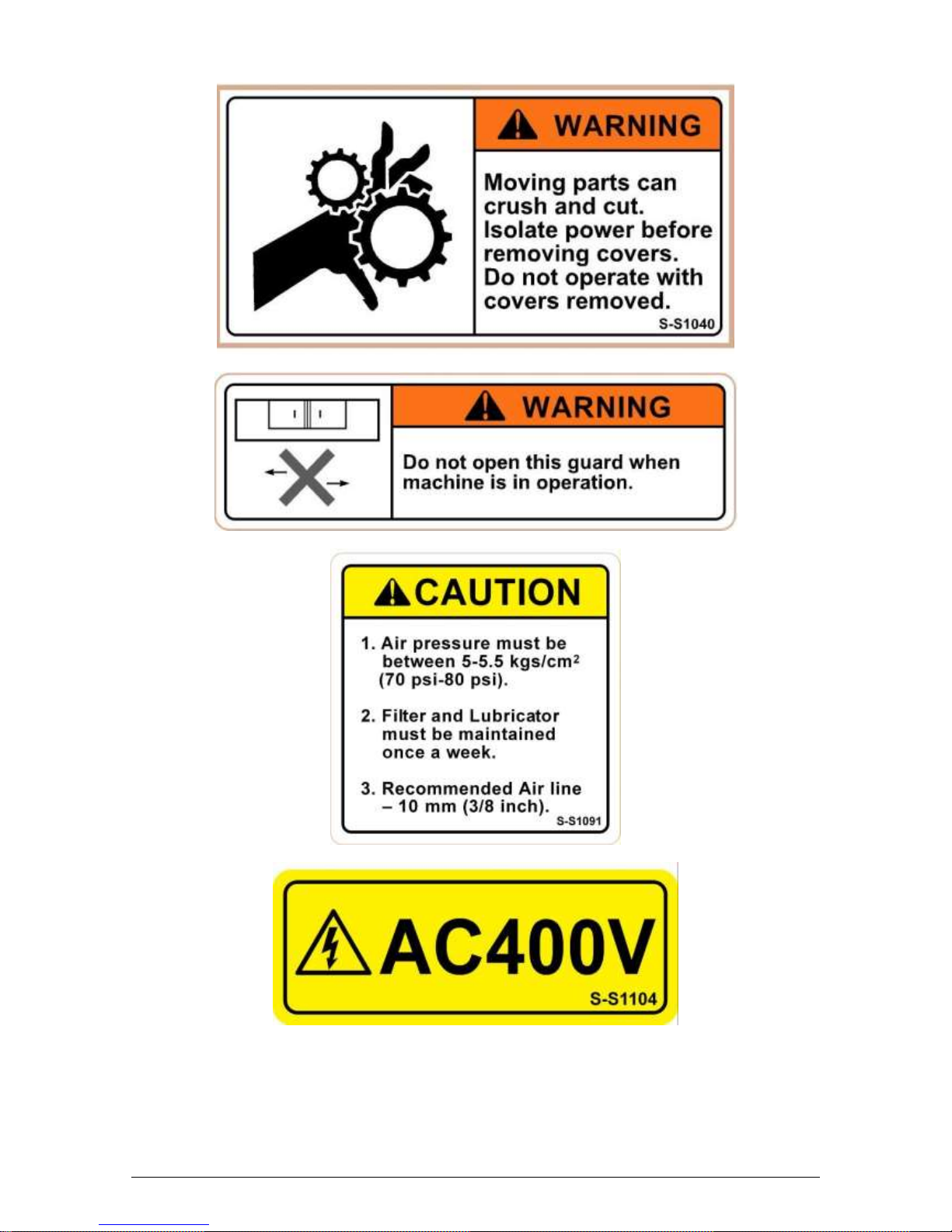
Safety & Information Labels Used on SMX Bed Mills
It is forbidden by law to deface, destroy or remove any of these labels
Page 8
4
XYZ Machine Tools Ltd
XYZ Bed Mill Safety, Installation, Maintenance, Service & Parts List Manual
Safety & Information Labels Used on SMX Bed Mills
It is forbidden by law to deface, destroy or remove any of these labels
Page 9

5
XYZ Machine Tools Ltd
XYZ Bed Mill Safety, Installation, Maintenance, Service & Parts List Manual
Safety & Information Labels Used on SMX Bed Mills
It is forbidden by law to deface, destroy or remove any of these labels
Page 10

6
XYZ Machine Tools Ltd
XYZ Bed Mill Safety, Installation, Maintenance, Service & Parts List Manual
Safety & Information Labels Used on SMX Bed Mills
It is forbidden by law to deface, destroy or remove any of these labels
Page 11

7
XYZ Machine Tools Ltd
XYZ Bed Mill Safety, Installation, Maintenance, Service & Parts List Manual
Safety & Information Labels Used on SMX Bed Mills
It is forbidden by law to deface, destroy or remove any of these labels
Page 12

8
XYZ Machine Tools Ltd
XYZ Bed Mill Safety, Installation, Maintenance, Service & Parts List Manual
1.5 EC Declaration of Conformity
The manufacturer, Southwestern Industries, declares that the ProtoTrak SMX mills conform to all the
relevant provisions of the:
•Machinery Directive 2006/42/EC
•Low Voltage Directive 2014/35/EU, and
•EMC Directive 2014/30/EU
The Technical file is available from XYZ Machine Tools, Woodlands Business Park, Burlescombe, Nr
Tiverton, EX16 7LL, United Kingdom.
1.6 Airborne Noise Emissions
The A-weighted emission sound pressure level at the operator’s workstation is 74dB(A).
(Measured in accordance with ISO 3744 with an uncertainty of 2.5dB.)
The figures quoted are emission levels and are not necessarily safe working levels. Whilst there is a
correlation between the emission and exposure levels, this cannot be used reliably to determine whether
or not further precautions are required. Factors that influence the actual level of exposure of the
workforce include characteristics of the work room and other sources of noise,. i.e. the number of
machines and other adjacent processes. Also the permissible exposure level can vary from country to
country. This information, however, will enable the user of the machine to make a better evaluation of the
hazard and risk.
Page 13

9
XYZ Machine Tools Ltd
XYZ Bed Mill Safety, Installation, Maintenance, Service & Parts List Manual
2.0 Installation
Read and understand this entire installation section before beginning the installation procedure.
2.1 Floor Plan, Layout & Space Requirements
2.1.1 SMX2500
Figure 1a - SMX 2500 - Machine Footprint
SMX2500
Footprint of Machine
587 x 1029 mm
Weight (approximate) net
1452 kg
Weight (approximate) shipping
1588 kg
Pallet Size
1778 x 1778 mm
A
Overall width
2565 mm
B
Overall length w/ electric box door open
1926 mm
C
Bed width
587 mm
D
Bed width between levelling screws
520.7 mm
E
Distance between levelling screws
825.5 mm
F
Bed length
1029 mm
Page 14

10
XYZ Machine Tools Ltd
XYZ Bed Mill Safety, Installation, Maintenance, Service & Parts List Manual
Figure 1b - SMX 2500 - Machine Footprint
SMX2500
G
Height of table from bottom of bed
864 mm
H
Maximum distance from spindle nose to table
597 mm
I
Maximum height of machine from bottom of bed to top of column cover.
1981 mm
J
Height of machine from bottom of bed to top of spindle motor
2261 mm
K
Width of machine including table
1778 mm
L
Length of machine with electric box door closed
1776 mm
Page 15

11
XYZ Machine Tools Ltd
XYZ Bed Mill Safety, Installation, Maintenance, Service & Parts List Manual
2.1.2 SMX3500
Figure 2a - SMX 3500 - Machine Footprint
Page 16

12
XYZ Machine Tools Ltd
XYZ Bed Mill Safety, Installation, Maintenance, Service & Parts List Manual
Figure 2b - SMX 3500 - Machine Footprint
2.1.3 SMX4000
Figure 3a - SMX 4000 - Machine Footprint
Page 17

13
XYZ Machine Tools Ltd
XYZ Bed Mill Safety, Installation, Maintenance, Service & Parts List Manual
Figure 3b - SMX 4000 - Machine Footprint
2.1.4 SMX 5000
Figure 4a - SMX 5000 - Machine Footprint
Page 18

14
XYZ Machine Tools Ltd
XYZ Bed Mill Safety, Installation, Maintenance, Service & Parts List Manual
Figure 4b - SMX 5000 - Machine Footprint
2.2 Uncrating
Carefully remove the wood crate and protective packaging, paying attention not to scratch, damage, or
mar any parts of the machine.
ATTENTION!
Immediately report, in writing, any damages observed at this time that can be attributed to
the transportation or improper handling/moving of the machine.
2.3 Installation Instructions & Checklist
Installer: Use this checklist to assure a complete set-up of the SMX bed mill.
Page 19

15
XYZ Machine Tools Ltd
XYZ Bed Mill Safety, Installation, Maintenance, Service & Parts List Manual
□
1.
Shut off power to the machine.
□
2.
Visually inspect the 415V -wiring going into the electrical panel. Visually verify the
wiring is correct per our wiring diagram. Make sure a strain relief is being used where
the wiring enters the cabinet. Have the customer repair any wiring discrepancies.
□
3.
Clean the machine if needed and remove any remaining grease.
□
4.
Unlock the table, saddle, and ram gib locks.
□
5.
Use an Allen wrench on the Z-axis ball screw end at the top of the column to manually
lower or raise the spindle head/ram.
□
6.
Make and check all the proper electrical connections from the pendant to the electric
box. See the pendant and electric box wiring diagrams.
□
7.
Turn on the power to the machine and to the pendant.
□
8.
Lubricate all the way surfaces and the ball screws.
□
9.
Jog the table, saddle, and ram back and forth until the way surfaces are well lubricated.
Oil should be visible on all the way surfaces.
□
10.
Check the level of the machine. The machine should be level to within 0.01 mm front to
back and 0.01 mm side to side. Even though it is the responsibility of the customer,
make any adjustments if necessary.
□
11.
Check to make sure that the E-Stop button is functioning correctly.
□
12.
Perform Service Code 12, Feed Forward Constant.
□
13.
As necessary, perform Service Code 123 to calibrate the X and Y-axis using a 150mm
standard.
□
14.
Perform Service Code 11 to automatically calculate the backlash for the X and Y-axis of
dual feedback machines (i.e. Newall scales with a motor encoder).
□
15.
As necessary, perform Service Code 127 and 128 to manually calculate the backlash for
the X and Y-axis of single feedback machines (i.e. motor encoder only).
□
16.
Check for positional accuracy and repeatability on the X and Y-axis using programs
XREPEAT.PT4 and YREPEAT.PT4 respectively. Positioning and repeatability values
should be less than or = to 0.01 mm. Programs can be found on flash drive under the
PT4 folder followed by the SWI TEST PROGRAMS folder.
□
17.
As necessary, perform Service Code 123 and press Z to calibrate the Z-axis ram using a
75mm standard.
□
18.
As necessary, perform Service Code 127 and 128 to manually calculate the backlash for
the Z-axis ram.
□
19.
Check for positional accuracy and repeatability on the Z-axis using program
ZREPEAT.PT4 Positioning and repeatability values should be less than or = to 0.01 mm.
□
20.
As necessary, perform Service Code 123 and press QUILL softkey to calibrate the Z-axis
quill using a 75mm standard.
□
21.
Perform Service Code 100 in both directions for the X, Y, and Z-axis to verify that the
feed rate shown on the display is at least 4560 mmpm if you have mechanical hand
wheels or 7620 mmpm if you have electronic hand wheels.
□
22.
Run the spindle at various speeds in both high and low gear for 15 minutes. Verify head
shifts from high to low gear smoothly. Test quill feed and spindle brake.
□
23.
As necessary, install the way covers.
□
24.
Use accessory key on pendant and make sure the coolant pump fires. The accessory
key should be in the ON position to test coolant pump. The control should be in DRO
mode.
□
25.
Check to ensure that the power drawbar tools load and unloads tools properly.
□
26.
Wipe down the machine prior to leaving.
Page 20

16
XYZ Machine Tools Ltd
XYZ Bed Mill Safety, Installation, Maintenance, Service & Parts List Manual
2.4 Lifting and/or Moving the Machine
CAUTION!
Depending on model, the SMX bed mill can weigh up to 3100 kg. Proper equipment of
sufficient capacity must be used when lifting or moving the machine. Only qualified
personnel should operate lifting equipment
Method 1 (see Figure 5):
1. Move the table as far forward as possible.
2. Insert 2 steel bars 50 mm dia. x 1300 mm long through both sides in the existing holes in the
machine base (front and back).
3. Use 4 off, steel cables (with protective sleeving) min. 19 mm dia. or 4 off, 4-ton slings.
4. Use cardboard pieces or other suitable protective sheets on both sides of the machine to prevent
scratching.
5. Remove any fasteners holding the machine to a pallet.
6. Lift the machine (the front of the machine should be lower than the back).
7. Insert the screws for levelling pads in their place in the bed.
8. Place the machine in its location (see floor plan and bed footprint drawing) carefully positioning
each levelling pad under each levelling screw.
9. Remove the lifting cable or sling, the steel bar and all protective cardboard.
Figure 5 - Lifting the Machine* - Method 1
*Machine image for indication only
Method 2 (see Figure 6):
1. Insert 2 steel bars 50 mm dia. x 1300 mm long through both sides in the existing holes in the
machine base (front and back).
2. Position 4 (two each side) wood vee blocks under the steel bars and over a suitable lift truck.
Page 21

17
XYZ Machine Tools Ltd
XYZ Bed Mill Safety, Installation, Maintenance, Service & Parts List Manual
3. Lift the machine up (somewhat tilted towards the front) 100-150 mm from the ground and move
it to its floor plan position.
WARNING!
The lift truck must have sufficient lifting capacity (4 tons) and be equipped with suitably long
forks.
4. Insert the 6 screws for the levelling pads in their place in the bed.
5. Place the machine in its location (see floor plan bed/footprint) carefully positioning each levelling
pad under each levelling screw.
Figure 6 - Lifting the Machine* - Method 2
*Machine image for indication only
2.5 Releasing the Head Counterweight Supports
In order to move (raise or lower) the spindle head, it is first necessary to remove the retaining rod that
supports the counterweight located on the right side of the machine. The retaining rod supports the
counterweight during shipping to prevent damage to the counterweights chains and sprocket.
1. Using an M8 Allen key, turn the Z-axis ball screw at the top of the column to slowly raise the
spindle head/ram. Remove the wood block that supports the spindle head/ram during shipment.
2. Remove the (3) socket head cap screws that secure the counterweight retaining rod to the
column.
3. Using an M14 Allen key, remove the bolt that secures the retaining rod to the counterweight.
4. Lower the spindle head slowly until the chain between the head and the counterweight is tight.
5. Lower the spindle head a little further until the retaining plug is loose. Remove retaining rod and
store for future use.
6. Do not continue to move the spindle head until all ways have been cleaned.
CAUTION!
Do not remove the steel rods unless they are loose.
2.6 Cleaning
1. Remove rust protective coating from the machine before moving any slideways (table, saddle,
ram, etc.).
2. The coating is best removed with clean, dry rags. Do not use a cleaning solution that may
damage the rubber way scrapers, plastic parts, or paint.
Page 22

18
XYZ Machine Tools Ltd
XYZ Bed Mill Safety, Installation, Maintenance, Service & Parts List Manual
WARNING!
Do not use petrol or other flammable cleaning agents for cleaning the machine.
3. It may be necessary to move back and forward, left and right, and up and down the table, saddle,
and the ram.
CAUTION!
Never move any of the above parts over ways that were not previously cleaned. Serious
damage to the TURCITE surface of slideways can occur.
4. Be certain the table, saddle, ram, and spindle move freely and smoothly over their entire length.
2.7 Levelling:
Levelling Tolerance for SMX 2500, 3500, 4000 & 5000 is 0.01 mm/2500 mm
1. Set the machine on its levelling pads on a solid, level floor prepared in accordance with the state
and local rules for machine tool installation.
2. Put one or two precision Spirit Levels or Electronic Levels in the centre of the table in the
positions illustrated in Figure 7.
3. Adjust the 4 corner levelling screws on their pads until the machine is level to 0.01 mm/2500 mm.
Snug the 2 middle levelling screws being careful to not affect the level of the machine.
4. If the machine must be anchored to the floor, follow the general instruction for installing machine
tools and use for levelling any well-known methods: shims, etc.).
5. If the machine must be installed on vibration mounts/pads (rubber, commercially available
levelling and vibration mounts, etc.) follow the instructions delivered with the mounts/pads,
ordering them to satisfy the load of the machine and the maximum weight of the workpiece.
6. When machine is correctly level, lock the adjusting screws in place with their hex nuts.
Figure 7 - Placement of Levels
Page 23

19
XYZ Machine Tools Ltd
XYZ Bed Mill Safety, Installation, Maintenance, Service & Parts List Manual
Figure 8 - Levelling Screws
2.8 Electrical Connection
The SMX 2500, 3500, 4000 & 5000 require a 400 volts, 3-phase, 50/60Hz supply plus an Earth
connection. No Neutral connection is required.
The incoming supply is wired to the machine through the electric cabinet located on the back of the
machine. The cable enters the cabinet through a compression gland fitted into the hole in the top of the
cabinet. The wires are connected to the incoming isolator. The main ground wire should be fastened to
the isolator mounting bracket with the screw provided.
The earth connection to the machine must be a minimum of 10mm2 (copper) due to high earth leakage
current (≤200mA).
DANGER!
The 400 VAC supply should only be wired by a qualified electrician.
2.9 Air Connection
The machines have a PCL/series 19, quick release air connection on the side of the electrical cabinet for
the power drawbar (see section 5).
The air preparation unit is fitted with a pressure regulator, factory set to 70 psi, water trap and lubricator.
2.10 Mounting the Display Pendant
The ProtoTRAK SMX display pendant mounts to the pendant arm with four 1/4-20 x ¾ SHCS. There is a
locating screw on the pendant arm to help align the pendant with the mounting holes.
CAUTION!
The locating screw in the arm is used for positioning. Keep a hold of the pendant until the
screws are fastened.
If the pendant arm rotates too freely, remove the painted cap on the bracket attached to the column and
tighten the hex nut to tension the hinge. Replace the cap.
2.11 Cable Interconnections
All cable interconnections are made at the factory. See Figure 11 for a complete illustration of cable
interconnections for all components. If electronic handwheels are fitted, these plug into the two, 15 pin
connectors near the top.
Make sure there is sufficient slack in the cables for when the pendant is rotated about the pendant arm.
The worst case is when the pendant is all the way forward toward the operator. The following drawing
illustrates pendant connectors.
Make sure there is a hardware (option) key plugged into the parallel port of the pendant. This key
activates any converters or options ordered. The part # for this key is 22648. The key must be
programmed according to the type of machine it is on and the options ordered.
The Machine ID port must have this key or the machine will not run.
CAUTION!
Make sure the main power is turned off on the back of the electrical cabinet before plugging
in the cables.
Page 24
20
XYZ Machine Tools Ltd
XYZ Bed Mill Safety, Installation, Maintenance, Service & Parts List Manual
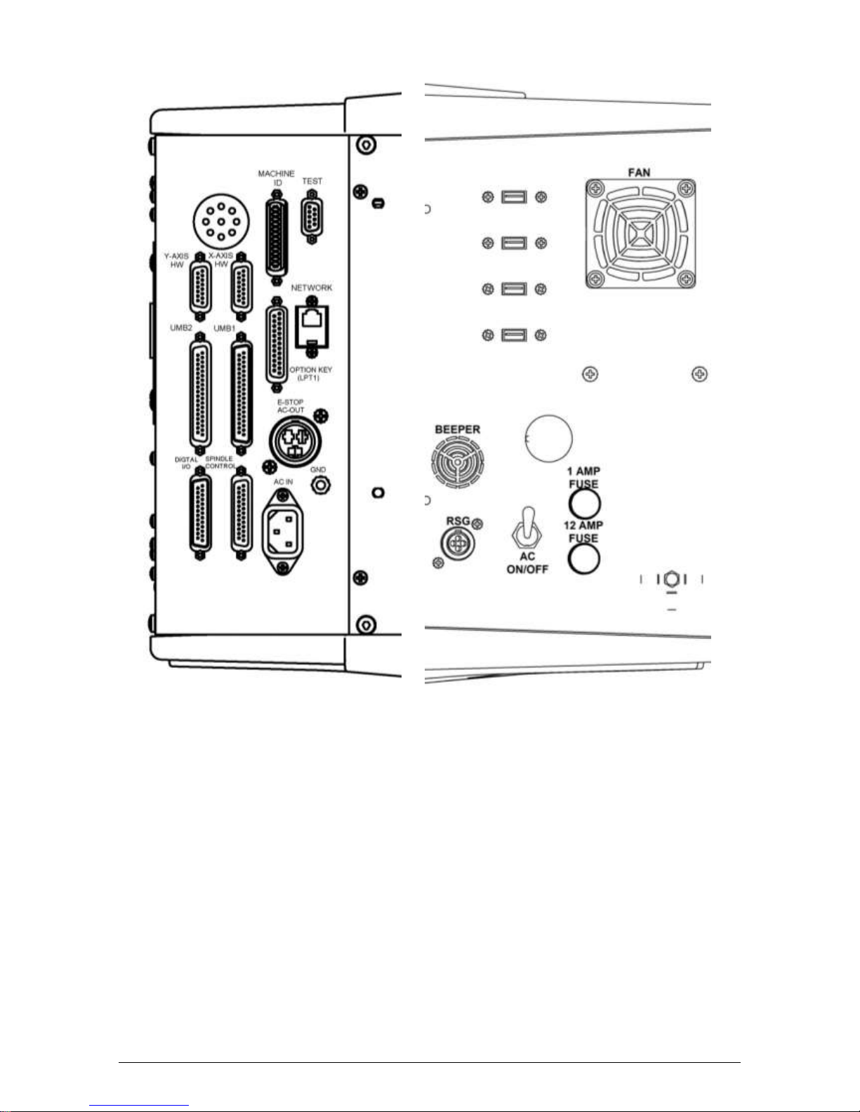
Left Side
Right Side
Figure 9 - Pendant Cable Connections
Page 25

21
XYZ Machine Tools Ltd
XYZ Bed Mill Safety, Installation, Maintenance, Service & Parts List Manual
Figure 10 - Pendant - Right Side (Earlier Models with Floppy Drive)
Page 26

22
XYZ Machine Tools Ltd
XYZ Bed Mill Safety, Installation, Maintenance, Service & Parts List Manual
Figure 11 – SMX 3500, 4000, 5000 Cable Connection Diagram
SMX2500 similar (less spindle control module and AC drive)
Page 27

23
XYZ Machine Tools Ltd
XYZ Bed Mill Safety, Installation, Maintenance, Service & Parts List Manual
2.12 Lubrication
2.12.1 Way Lubrication
The auto lube system provides centralised, automatic lubrication for the ways and ballscrews. The lube
pump has a 2-litre reservoir and should be kept filled with ISO 32 slideway oil or equivalent.
The pump has an audible alarm for low oil pressure or low oil level.
The pump is factory set to:
Interval Time: 20 min.
Discharge Time: 5 sec
Discharge Pressure: Approximately 690-1030 kPa (100 – 150 psi)
The interval time and discharge time can be set electronically:
SMX2500:
o Use the buttons on the side of the lube pump:
INT (Interval): this button programs the interval between pumping cycles. Each press of
the button increases the interval by one minute.
DIS (Discharge): this button programs the amount of time the pump will discharge
each pumping cycle. Each press of the button increases the discharge
time by one minute.
FEED: this button is used to manually operate the pump.
RST: this button tells the pump to discharge for the time programmed.
SMX3500, 4000, 5000:
o Interval time: Use service code 301.
o Discharge time: Use service code 302.
o Manually cycle pump: Use service code 300.
o See section 4.8 for details of accessing Service Codes within the ProtoTrak control.
The lube pump should be operated manually at the beginning of each shift (using the FEED button or
code 300).
CAUTION!
Failure to manually activate the pump at the beginning of each day, or allowing the Auto
Lube to run dry may cause severe damage to the way surfaces and ballscrews.
To adjust the amount of Discharge Pressure displayed on the lube pump gauge, loosen the jam nut and
turn the adjustment screw located on the top right side of the lube pump while the lube pump is
activated.
See Figures 66 to 71 for machine lubrication drawings.
2.12.2 Head Lubrication
Once Each Week:
1. Fill the oil cup on the front of the head with ISO 32. This oil lubricates the quill feed assembly.
2. Fill the oil cup on the right hand side of the head with ISO 32 oil. This oil lubricates the quill
assembly.
3. Extend the quill fully and apply a coating of ISO 32 oil to the outside diameter of the quill.
Every Four Months:
1. Apply a good grade of general-purpose grease through the grease fittings on the back of the head
and on the left side of the head. This grease lubricates the Low range gear set and the feed
change gears respectively.
2. Remove X handwheel drive cover and apply general-purpose grease to the drive gears.
Page 28

24
XYZ Machine Tools Ltd
XYZ Bed Mill Safety, Installation, Maintenance, Service & Parts List Manual
2.13 Machine Specifications
Model Name
2500
3500
4000
5000
Table Size
1245 x 229
1372 x 356
1474 x 356
1930 x 355
T-Slots (number x width)
3 x 15.9
4 x 15.9
4 x 15.9
4 x 15.9
Travel (X, Y, Z axis)
762 x 381 x
560
787 x 508 x
450
1016 x 596 x
520
1524 x 596 x
520
Quill Diameter
86
105
116
116
Maximum Quill Travel
127
127
127
127
Spindle Taper
R8
40 ISO
40 ISO
40 ISO
Spindle Speed Range
60 - 3500
40 - 5000
40 - 5000
40 - 5000
Spindle Centre to Column Face
457
520
610
610
Spindle Motor Power (HP)
3 5 7.5
7.5
Maximum Weight of Workpiece
600 Kg
600 Kg
850 Kg
850 Kg
Height of table from bottom of bed
864
835
956
956
Max spindle nose to table
597
620
620
620
rapid traverse X, Y, Z – standard
handwheels
3800
3800
3800
3800
Rapid traverse, X, Y, Z – electronic
handwheels
3800
6350
6350
6350
Overall Dimensions of Machine
(height includes 30mm levelling allowance)
587 x 1029 x
2480
3600 x 3143
x 2470
4405 x 3143
x 2690
5805 x 3143
x 2690
Shipping Weight
1900 Kg
2300 Kg
2750 Kg
3100 Kg
Electrical Power Requirements
20 Amp
25 Amp
25 Amp
25 Amp
2.14 ProtoTRAK SMX Control Hardware
3-axis CNC, 3-axis DRO
Precision ground ballscrews in the table, saddle and ram to ensure smooth accurate contours
without backlash
Feedrate override of programmed feedrate and rapid
Modular design simplifies service and maximizes uptime
Control Pendant (part number 24000-8):
o 1.66 GHz PC-based processor
o 1 Gb of RAM
o 1 Gb flash drive
o 4 USB connectors
o 267 mm colour LCD for clear presentation of prompts, status information and part
graphics
X, Y and Z Axes Motors (part number 24428-1):
o D.C. Servo Motors
o 560 in-oz. continuous torque
Page 29
25
XYZ Machine Tools Ltd
XYZ Bed Mill Safety, Installation, Maintenance, Service & Parts List Manual
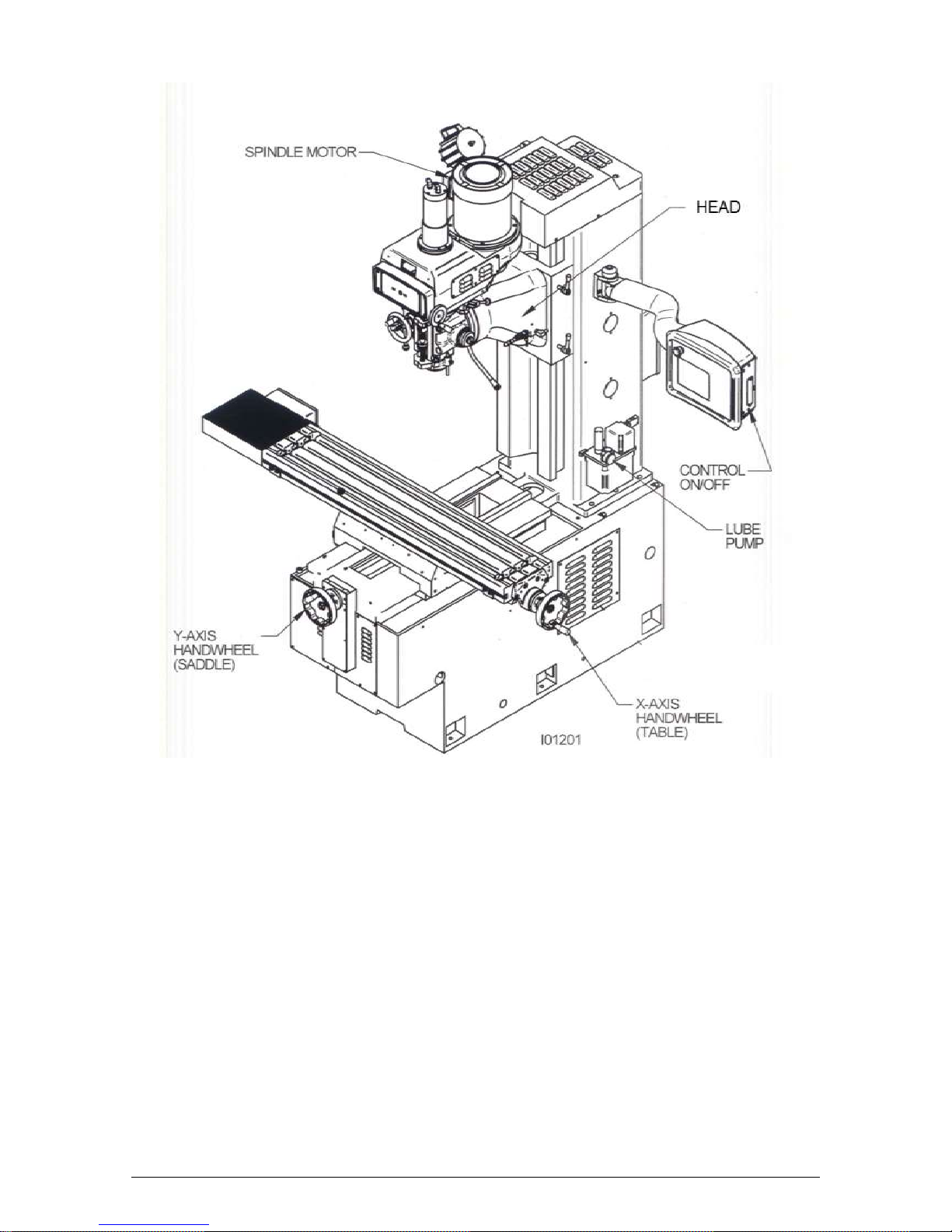
Figure 12 - The XYZ SMX Bed mill machine overview
Guards not shown for clarity
Page 30

26
XYZ Machine Tools Ltd
XYZ Bed Mill Safety, Installation, Maintenance, Service & Parts List Manual
3.0 Troubleshooting by Symptom
Use this section to begin the process of resolving a problem. Each symptom type is described in a few
words and then more fully described in an explanatory paragraph. Following this, is a chart that directs in
the most logical steps.
DANGER!
Some of these checks involve accessing potentially hazardous mechanical or electrical
systems. These checks must only be carried out by competent personnel.
3.1 Problems Relating To Machining Results
3.1.1 Poor Finish
The part finish is marred with scallops or is very rough.
Do the following Service Codes and document values:
Code 33 Software Identification. This is needed if you call Customer Service
Code 11 Measures backlash in the system (Only used on Dual Feedback systems)
Code 12 Feed Forward Constant
Code 127 Measures backlash in the system (not used on Dual Feedback systems)
Code 128 Enter backlash compensation
Possible Cause
Check This
Too much backlash entered for code
128 or calculated with code 11.
Verify nothing is mechanically loose and the backlash values are
not higher than what physically is in the system.
Machine Tool & Setup problem
Check for any looseness in the setup (Tool, Tool holder, Part,
Vice, or Fixture). Check the condition and type of cutter being
used, type of material, RPM and Feedrate, etc. See Machine
Tool & Setup Section 4.1
Table, Saddle, or Ram Locks are
locked
Make sure the Table, Saddle, and Ram Locks are unlocked.
Never use gib locks with a CNC machine.
Inadequate or no Lubrication to
Ballscrews and Way surfaces
Make sure all the Way surfaces are getting proper lubrication. If
not, check to make sure that the lube pump is functioning
properly. Also check for any pinched or blocked oil lines. See
Lubrication Section 4.1.3
X, Y, and Z-axis Gibs are not
adjusted properly
Check the adjustment of the X, Y, and Z-axis Gibs. See X, Y,
and Z-axis Gib Adjustments in Section 5.2.1.
X & Y-axis Drive Trains are loose
Check Repeatability using the Repeatability and Positional
Accuracy procedure. Step by step, carefully inspect the Drive
Train for any looseness. It may be necessary to disassemble
and then reassemble the Drive Train. See Mechanical Drive
Train (X, Y) Section 4.2
Way surfaces are pocked, scarred, or
excessively worn
Visually check the condition of all the Way surfaces. For
machines that may have excessively worn Way surfaces you
may need to adjust the Gibs in this area. This will affect
performance when using the machine outside of this area.
Check lubrication to affected areas.
3.1.2 Circles Out of Round
Circles are not round within 0.05 mm TIR over 75 mm DIA. This is best measured by placing a dial
indicator in the quill and sweeping around the part.
Note: The typical slideway-milling machine is not capable of achieving more precise results. If more
precise circles are required, then it is recommended to use a precision boring head/boring bar.
Page 31

27
XYZ Machine Tools Ltd
XYZ Bed Mill Safety, Installation, Maintenance, Service & Parts List Manual
Do the following Service Codes and document values:
Code 33 Software Identification. This is needed if you call Customer Service
Code 11 Measures backlash in the system (Only used on Dual Feedback systems)
Code 12 Feed Forward Constant
Code 127 Measures backlash in the system (not used on Dual Feedback systems)
Code 128 Enter backlash compensation
Possible Cause
Check This
Torque values on X and Y-axis are
too high.
Make sure torque is lower than 20 in-lbs. Normal values for a
machine that is aligned and adjusted properly should be
between 10 and 15 in-lbs when driving axis. Make sure torque
is consistent across axis travel.
Machine Tool and Setup problem
Check for any looseness in the setup (Tool, Tool holder, Part,
Vice, or Fixture). See Machine Tool & Setup - Section 4.1
Machine not level
Verify that the machine is level to specification.
Head is not Trammed
Verify that the Head is Trammed to specification. See
Tramming the Head
X, Y, and Z-axis Gibs are not adjusted
properly
Check the adjustment of the X, Y, and Z-axis Gibs using the X,
Y, and Z-axis Gib adjustment procedures.
Calibration or Backlash problem
Recalibrate the machine. Reset the Backlash. Check
Repeatability and Positional Accuracy. See Calibration &
Backlash Constants Section 5.2.2
Newall Scale problem
Make sure that the Newall Scale is installed correctly according
to the Newall Scale Installation procedures. Check for any
loose brackets or misalignment etc. Also, check to make sure
the Newall Scale assemblies are functioning correctly. See
Newall Scales Sections 4.6 & 4.7.
X & Y-axis Drive Trains are loose
Check Repeatability using the Repeatability and Positional
Accuracy procedure. Step by step, carefully inspect the Drive
Train for any looseness. It may be necessary to disassemble
and then reassemble the Drive Train. See Mechanical Drive
Train (X, Y) Section 4.2
Head Bolts are loose
Verify that all the head bolts are tight.
3.1.3 Taper Cut on a Programmed Straight Line Move
An unwanted tapered cut occurs, when the machine is programmed to move in a straight line along either
the X or Y-axis. The DRO shows motion of a few thousandths of an inch in the axis that is not supposed
to be moving.
Explanation: For straight line cuts along the X or Y-axis, the control is designed to lock the motor of the
axis that is not moving. A taper is created when there is play in the system. The force of the tool shoves
the table or saddle out of position.
The system will respond to being pushed out of position by making an adjustment at the end of the
move.
An unwanted tapered cut is the result of looseness in the system.
Do the following Service Codes and document values:
Code 33 Software Identification. This is needed if you call Customer Service
Code 11 Measure's the backlash in the system. Only used on machines with Dual Feedback
systems
Code 12 Feed Forward Constant
Code 127 Measure's the backlash in the system. Only used on machines with no Dual Feedback
Code 128 Enter backlash compensation
Page 32

28
XYZ Machine Tools Ltd
XYZ Bed Mill Safety, Installation, Maintenance, Service & Parts List Manual
Possible Cause
Check This
Machine Tool & Setup problem
Check for any looseness in the setup (Tool, Tool holder, Part,
Vice, or Fixture). See Machine Tool & Setup Section 4.1
X, Y, and Z-axis Gibs are loose
Check the adjustment of the X, Y, and Z-axis Gibs using the X,
Y, and Z-axis Gib adjustment procedures. See Section 5.2.1
X and Y-axis Drive Trains are loose
Check Repeatability using the Repeatability and Positional
Accuracy procedure. Step by step, carefully inspect the Drive
Train for any looseness. It may be necessary to disassemble
and then reassemble the Drive Train. See Mechanical Drive
Train (X, Y) Section 4.2
3.1.4 Parts Have Incorrect Dimensions
Parts are being machined with dimensions that are different than those programmed. Typical accuracy
expectations should be:
Circles: 0.05 mm TIR over 75 mm DIA
Positional Accuracy: 0.01 mm
Repeatability: 0.01 mm
Note: The typical slideway-milling machine is not capable of achieving more precise results.
The system should be expected to repeat within the resolution of the displayed DRO numbers of 0.01
mm.
Do the following Service Code:
Code 33 Software Identification. This is needed if you call Customer Service
Code 123 Calibration
Code 11 Measure's the backlash in the system. Only used on machines with Dual Feedback
systems
Code 12 Feed Forward Constant
Code 127 Measure's the backlash in the system. Only used on machines with no Dual Feedback
Code 128 Enter backlash compensation
3.1.4.1 Every Part Has the Same Error
Possible Cause
Check This
Machine Tool & Setup problem
See Machine Tool & Setup Section 4.1
Programming Error
In the program, look for common errors in programming such
as transposing numbers, tool diameters, and pressing INC SET
when ABS SET is meant. This is especially suspected if the
dimensional errors are larger than a few thousandths. See the
Controls Programming, Operations and Care manual.
Configuration file that contains
calibration file and backlash
constants has been erased or
corrupted.
Verify configuration file (Code 313) does not read default
values. Load saved configuration file from floppy disk in
electrics cabinet with Code 141.
Calibration or Backlash problem
Recalibrate the machine. Reset the Backlash. Check
Repeatability and Positional Accuracy. See Calibration &
Backlash Constants
3.1.4.2 The Dimensional Errors Are Random or Accumulate in Size Over the Part Program
Run
Possible Cause
Check This
Machine Tool & Setup problem
See Machine Tool & Setup Section 4.1
Page 33

29
XYZ Machine Tools Ltd
XYZ Bed Mill Safety, Installation, Maintenance, Service & Parts List Manual
Scale problem
Make sure that the Scale is installed correctly according to the
manufacturer’s instructions. Check for any loose brackets or
misalignment etc. Also, check to make sure the Scale
assemblies are functioning correctly. See Scales Sections 4.6 &
4.7
X and Y-axis Drive Trains are loose
Check Repeatability using the Repeatability and Positional
Accuracy procedure. Step by step, carefully inspect the Drive
Train for any looseness. It may be necessary to disassemble
and then reassemble the Drive Train. See Mechanical Drive
Train (X, Y) Section 4.2
3.2 Problems Regarding the Motion of the Machine
3.2.1 Run Away Axis
The axis makes an unwanted move at rapid speed in one direction and faults out. This is usually caused
by an encoder signal being interrupted.
Do the following Service Codes:
Code 33 Software Identification. This is needed if you call Customer Service
Code 100 Axis open loop test. Used to check the maximum feedrate of an axis and if the
encoders are counting properly
Possible Cause
Check This
Newall scales are counting in
opposite direction of motor encoder
Reverse directions with codes 321 and 322
The home positions or tools are not
set correctly
See the Controls Programming, Operations and Care manual.
The Sensor or Glass Scale is not
reading.
See TRAK Sensors or Glass Scales diagnostic Section 4.6 or 4.7
Bad Motor Encoder
See Motor diagnostics Section 4.4
3.2.2 Slow Down Axis
The axis slows down and moves at a feedrate that is lower than rapid or than the programmed feedrate.
Do the following Service Codes:
Code 33 Software Identification. This is needed if you call Customer Service
Code 100 Axis open loop test. Used to check the maximum feedrate of an axis and if the
encoders are counting
Code 129 Set's the maximum allowable arc accuracy error. This applies to arcs only
Possible Cause
Check This
The maximum allowable Arc
Accuracy is set too low.
This value will only slow down the machine during arc moves.
The factory default is set at 0.025 mm. Perform Code 129 to
check or change this value. See Service Codes section
Incoming AC voltage is inadequate
Perform Code 100. See Service Codes - Section 4.9 and
Electrical Section 4.8
Table, Saddle, or Ram Locks are
locked
Make sure the Table, Saddle, and Ram Locks are unlocked.
Inadequate or no Lubrication to
Ballscrews and Way surfaces
Make sure all the Way surfaces are getting proper lubrication. If
not, check to make sure that the lube pump is functioning
properly. Also check for any pinched or blocked oil lines. See
Lubrication Section 4.1.3
Page 34

30
XYZ Machine Tools Ltd
XYZ Bed Mill Safety, Installation, Maintenance, Service & Parts List Manual
X, Y, and Z-axis Gibs are not
adjusted properly
Check the adjustment of the X, Y, and Z-axis Gibs using the X,
Y, and Z-axis Gib adjustment procedures.
Binding in the Drive Train
Check Repeatability using the Repeatability and Positional
Accuracy procedure. Check the torque reading of the Drive
Train. Step by step, carefully inspect the Drive Train for any
binding. It may be necessary to disassemble and then
reassemble the Drive Train. See Mechanical Drive Train (X, Y)
Section 4.2
Servo Drive failure
See Servo Drive Section 4.5
Motor failure
See Motor Section 4.4
3.2.3 Axis Will Not Jog
The system powers up but will not respond to the jog command.
Do the following Service Codes and procedures:
Code 33 Software Identification. This is needed if you call Customer Service
Code 100 Axis open loop test. Used to check the maximum feedrate of an axis and if the
encoders are counting
Possible Cause
Check This
Improper Boot-up
Shut down the system and wait 10 seconds before rebooting
E-Stop is pressed in
Check E-Stop. Especially if both axes will not jog
E-Stop reset button
Press the E-Stop reset button on the side of the pendant
Servo Drive failure
Especially, if only one axis will not jog;
See Servo Driver Section 4.5
Shorted motor
See Motor Section 4.4
Poor cable or wiring connections
See Electrical Connection Section 2.12
Computer/Pendant failed
See Computer/Pendant diagnostics Section 4.3
3.2.4 Axis Motor Motion is not Smooth
While under motor power, the motion is not smooth. The motion appears to be "rough" or jerky”.
Do the following Service Codes and procedures:
Code 33 Software Identification. This is needed if you call Customer Service
Code 11 Measure's the backlash in the system. Only used on machines with Dual Feedback
systems
Code 12 Feed Forward Constant. High feed forward constants will cause an unstable servo
system
Code 127 Measure's the backlash in the system. Only used on machines with no Dual Feedback
Code 128 Enter backlash compensation
Code 100 Axis open loop test. Used to check the maximum feedrate of an axis and if the
encoders are counting
Possible Cause
Check This
X, Y, and Z-axis Gibs are not
adjusted properly
Check the adjustment of the X, Y, and Z-axis Gibs using the X,
Y, and Z-axis Gib adjustment procedures.
Scale problem
Make sure that the Scale is installed correctly according to the
manufacturer’s instructions. Check for any loose brackets or
misalignment etc. Also, check to make sure the Scale
assemblies are functioning correctly. See Scales Section 4.6 &
4.7.
Page 35

31
XYZ Machine Tools Ltd
XYZ Bed Mill Safety, Installation, Maintenance, Service & Parts List Manual
Calibration or Backlash problem
Recalibrate the machine. Reset the Backlash. Check
Repeatability and Positional Accuracy. See Calibration &
Backlash Constants section.
Binding in the Drive Train
Check Repeatability using the Repeatability and Positional
Accuracy procedure. Check the torque reading of the Drive
Train. Step by step, carefully inspect the Drive Train for any
binding. It may be necessary to disassemble and then
reassemble the Drive Train. See Mechanical Drive Train (X, Y)
Section 4.2
3.2.5 Vibration in Motion
While axis is moving there is vibration or noise coming from the X or Y-axis.
Do the following Service Codes and procedures:
Code 11 Measure's the backlash in the system. Only used on machines with Dual Feedback
systems
Code 12 Feed Forward Constant. High feed forward constants will cause an unstable servo
system
Code 127 Measure's the backlash in the system. Only used on machines with no Dual Feedback
Code 128 Enter backlash compensation
Code 123 Calibrate
Possible Cause
Check This
Too much backlash entered in Code
128 or Code 11.
Recheck the machines backlash.
Inadequate or no Lubrication to
Ballscrews and Way surfaces
Make sure all the Way surfaces are getting proper lubrication. If
not, check to make sure that the lube pump is functioning
properly. Also check for any pinched or blocked oil lines. See
Lubrication section
X, Y, and Z-axis Gibs are not
adjusted properly
Check the adjustment of the X, Y, and Z-axis Gibs using the X,
Y, and Z-axis Gib adjustment procedures.
Gibs not making good contact.
Pull gibs out and mark with a blue die to check where the gibs
are making contact. It is recommended that the gibs uniformly
contact at least 80% of the surface.
Binding or looseness in the Drive
Train
Check Repeatability using the Repeatability and Positional
Accuracy procedure. Check the torque reading of the Drive
Train. Step by step, carefully inspect the Drive Train for any
binding or looseness. It may be necessary to disassemble and
then reassemble the Drive Train. See Mechanical Drive Train (X,
Y) Section 4.2
Axis Motor belt too tight.
Loosen belt.
Misalignment of ball screw
See Mechanical Drive Train (X, Y) Section 4.2
3.2.6 Searching Axis
The handwheels are slowly turning back and forth when the servos are engaged. Several thousandths of
motion are observed on the vernier dial and the frequency is one cycle every couple of seconds.
Do the following Service Code and procedures:
Code 11 Measures backlash in system. (Used only with glass scales and sensors.)
Code 12 Sets a feed forward power constant to drive axis motors
Code 128 Backlash compensation on single feedback machines
Page 36

32
XYZ Machine Tools Ltd
XYZ Bed Mill Safety, Installation, Maintenance, Service & Parts List Manual
Possible Cause
Check This
Most often causes by excess
backlash compensation
Check physical backlash in system and re-enter in code 128.
Run code 11 on single feedback machines
High feed forward values
Check ball screw torque. Typical values should be between 10
to 15 in-lbs for the 2500 & 3500 & 15-20 in-lbs for the 4000 &
5000.
Excessive friction in the sliding ways
Lubrication, gib adjustments, gib locks.
See Machine Tool & Setup - Section 4.1
Looseness in the drive train
The drive train of the axis that is searching, especially the
tightness of the drive assembly.
See Mechanical Drive Train (X, Y) - Section 4.2
3.3 Problems Relating to the Operation of the Control
3.3.1 Display Blanks
The display is completely blank.
Possible Cause
Check This
Screen saver has been activated
Press any key to turn back on. All LED keys on pendant will
blink when the screen saver is on. Press any key to deactivate.
Hitting this key will not activate any feature on the control.
The system has shut down
Turn the power switch off, check the computer/ pendant fuses
and cable connections. See Electrical Section 4.8
Fuse blown in pendant
Remove fuse and check continuity
Display/Computer/Pendant failed
See Computer/Pendant Section 4.3
3.3.2 Bad Picture on the Display
The display has strange characters, horizontal bars or other unfamiliar images, or the display continually
rolls.
Possible Cause
Check This
Display/Computer/Pendant failed
See Computer/Pendant Section 4.3
3.3.3 Keyboard Lockup
The screen display is normal, but the system will not respond to key presses.
Do the following Service Codes and procedures:
Code 81 press each key on the pendant. The screen will display a keypad that signifies if a key
is working. The pendant will also beep.
Possible Cause
Check This
Voltage drop/spike has occurred
Shut down the system and wait 10 seconds to reboot the
system.
Remote Stop-Go (RSG) switch has a
short (if connected)
Remove the RSG. Turn the system off and then on again. If the
problem goes away and then re-appears when the RSG is
plugged-in, replace the RSG.
Computer/Pendant failed
See Computer/Pendant Section 4.3
3.3.4 Axes Fault (X, Y or Z)
The program run or jogging operation is interrupted with a Fault Message on the display.
Page 37

33
XYZ Machine Tools Ltd
XYZ Bed Mill Safety, Installation, Maintenance, Service & Parts List Manual
Do the following Service Codes and procedures:
Code 33 Software Identification. This is needed if you call Customer Service
Code 11 Measures the backlash in the system. Only used on machines with Dual Feedback
systems
Code 12 Feed Forward Constant. High feed forward constants will cause an unstable servo
system
Code 100 Axis open loop test. Used to check the maximum feedrate of an axis and if the
encoders are counting
Possible Cause
Check This
Cable connection problems
Check umbilical 1 and 2. Check #1 for X and Y-axis problems
and #2 for the Z-axis.
X, Y, and Z-axis Gibs are adjusted
extremely tight
Check the adjustment of the X, Y, and Z-axis Gibs using the X,
Y, and Z-axis Gib adjustment procedures. See X, Y, and Z-axis
Gib Adjustments Section 5.2.1
Excessive friction in the slideways
See Machine Tool & Setup Section 4.1
Binding or looseness in the Drive
Train
See Mechanical Drive Train (X, Y) Section 4.2
Incoming electrical power
Incoming voltage. See Electrical Section 4.8
Measurement system not functioning
properly
See Section 4.6 or 4.7
Servo Drive failure
See Servo Driver - Section 4.5
Motor failure
See Motor diagnostics, Section 4.4
Computer/Pendant failure
See Computer/Pendant diagnostics, Section 4.3
3.3.5 Problems Reading the Floppy Disk; Programs Not Saved Properly. The floppy
drive will not read or write programs from a disk.
Possible Cause
Check This
Improper Boot-up
Shut down the system and wait 10 seconds before rebooting
Floppy Disk failure
The Floppy Disk may be bad. See if the Floppy Disk can be read
by a Personal Computer. Does the green light on the floppy
drive come on when you access the disk? If so, power is
getting to the floppy drive. If not check connections of floppy
drive inside the computer module. See Computer/Pendant
Section 4.3 for more information.
Floppy Disk full
Put the Floppy Disk into a Personal Computer to see how many
bytes remain. A floppy can typically hold 1.4 MB of
information.
3.3.6 System Will Not Boot-Up
The system does not boot-up when the switch is turned on.
Possible Cause
Check This
Flash Drive failure
When the Computer Module starts the boot-up process, look at
the 8th line on the Display Screen. If the Mother Board of the
Computer Module is communicating with the Flash Drive you
will see "Detecting IDE Primary Master…Scan Disk SDCFB-256".
If the Mother Board of the Computer Module is not
communicating with the Flash Drive you will see "Detecting IDE
Primary Master … None".
Page 38

34
XYZ Machine Tools Ltd
XYZ Bed Mill Safety, Installation, Maintenance, Service & Parts List Manual
Also, check the wiring connection between the Flash Drive and
the Mother Board. See Computer/Pendant diagnostics Section
4.3.
Computer/Pendant has failed
See Computer/Pendant diagnostics Section 4.3.
3.3.7 System Reboots by Itself
During operation, the screen suddenly blanks and then shows that the system has begun the boot-up
sequence.
Possible Cause
Check This
Interruption of 110 V power to
pendant
Using a Voltmeter, check the incoming 110VAC to the pendant.
Poor wiring and cable connections
Check for any loose wiring or cables
Computer/Pendant failed
See Computer/Pendant diagnostics Section 4.3
3.3.8 System Shuts Off
During operation, the system shuts off and will not turn back on.
Possible Cause
Check This
Fuse blown in pendant
Remove fuse and check continuity
Poor wiring and cable connections
Check for any loose wiring.
Transformer output
Check 110 V Transformer output
Computer/Pendant has failed
See Computer/Pendant diagnostics Section 4.3.
3.3.9 Will Not Hold Calibration
The control will not hold calibration. Go to the "Configuration Values" screen and write down the
calibration values for the motor encoders (Encoder) and the position feedback encoders (Scales). The
calibration values are written in Hexadecimal. Recalibrate the system and see if the values change. Turn
the system off and on and see if the values are held.
Do the following service codes and procedures:
Code 33 Software Identification. This is needed if you call Customer Service.
Code 313 Configuration Values
Code 123 Calibration Mode
Possible Cause
Check This
Configuration file corrupt
Load default configuration by going to code 313
Not saving Calibration values
Replace Computer/Pendant module.
If calibration factors are being saved, but the measurements are not repeating or are not accurate:
See Measurements Are Not Repeating
See Measurements Are Not Accurate
3.3.10 Auxiliary Functions Not Working
The Auxiliary Functions will not turn on or off at the programmed times. There are 3 Auxiliary Functions:
1. Turns coolant pump on or off.
2. Sends an electrical signal to rotate the turret on an indexer.
3. Turns the "Spindle Off" at the end of a programmed event.
In order to run the above auxiliary functions in run mode the accessory key on the front of the pendant
must be in the AUTO mode.
All of the auxiliary function signals are carried down to the cable breakout box through umbilical #2. Each
function then has its own relay inside this box. If one of these relays fail then these features will not
work.
Page 39

35
XYZ Machine Tools Ltd
XYZ Bed Mill Safety, Installation, Maintenance, Service & Parts List Manual
Do the following service code and procedures:
Code 33 Software Identification. This is needed if you call Customer Service.
Code 329 Control Outputs. Enables the outputs to be turned on/off manually (Press Code F first
to access codes 328 through to 330)
Possible Cause
Check This
Blown fuse
Check the fuses feeding the coolant pump and also the coolant
pump control circuit.
Poor cable connections
Check all the cable connections on the cable breakout box and
Coolant Pump. In particular, check umbilical # 2 cable, which
carries the auxiliary function signals.
Bad cable breakout box
Check for continuity between the following pins when the
corresponding aux function is activated:
Coolant connector: 1 and 4
Indexer connector: 3 and 4
Spindle connector: 1 and 4
3.3.11 Emergency Stop Error (E-Stop)
The E-Stop turns the power off to the axis and spindle motors. SMX Bed Mills have an E-stop on the front
of the pendant and a reset button on the side of the pendant. (See figures 9 & 10). When the E-stop is
activated:
Power to the cable break out box (from the pendant AC E-stop Out connector) is isolated via the
E-stop relay inside the pendant. This isolates power to the axes motors.
The spindle AC drive power is turned off by a contactor (K1), located on the power module. The
contactor (K1) is turned off by the dual channel safety relay, which monitors the pendant E-stop.
(for SMX2500, the safety relay removes 24VAC power to the spindle contactors)
The E-stop LED on the spindle control module will be on when the e-stop is in the out position. The LED
will turn off when the E-stop is depressed. (See figure 10).
If the E-Stop button is depressed, and no message is displayed on the screen, then either the pendant,
spindle control module, cables from pendant to spindle control module, or cables from spindle control
module to dual channel relay (safety relay) are at fault.
Possible Cause
Check This
E-Stop reset button
Press the E-Stop reset button on the side of the pendant.
Bad pendant
Does 110 V power come out of the AC E-stop Out connector on the
pendant? If yes and the screen has an E-stop message then
replace the pendant.
Poor cable connection
Check spindle control cable connection and Euro connector
connections.
3.3.12 Limit Switch Error
Limit switches are installed on the table, saddle, and head to prevent serious damage to the machine in
the event of overtravel. In the event a limit switch is triggered, a limit switch error will appear on the
screen.
To return the machine to its normal state of operation, perform the following procedure:
1. Jog the table, saddle, or head off the switch.
2. Press the "Mode" or "Return" key to reset the control
3. Press the "DRO" key to access the Jog function again.
Page 40

36
XYZ Machine Tools Ltd
XYZ Bed Mill Safety, Installation, Maintenance, Service & Parts List Manual
Limit switches can be turned on or off with Service Code 312, however, limit switches should normally be
kept on.
Possible Cause
Check This
Limit Switches are triggered
Reset the Limit Switches using the procedure described above.
Poor Limit Switch Cable
connection
Check for any pins that are loose, pushed in, or bent. Verify that
there is a good connection between the cables on the cable
breakout box.
Limit Switch failure, try this:
Swap over 2 limit switch cables
on the cable breakout box.
Does the limit switch problem move to the other axis? If it does
then the switch is most likely the problem. If it stays with the
original axis then it could be the cable breakout box or pendant.
3.4 Problem with the Measurements
3.4.1 X, Y and Z-Axis Measurements Do Not Repeat
With a dial indicator mounted to the bottom of the spindle, touch off a fixed surface either in the X or Yaxis direction and then set the DRO equal to 0. Crank away several centimetres and then touch off again
at the same place. If the reading has not returned to 0 on the DRO, zero the display and repeat the
procedure. If the measurement does not repeat, you have a repeatability problem that must be resolved.
Test for accumulative error by moving the axis a number of times to see if the error gradually grows by a
small amount. If so, it may be caused by a misaligned sensor or scale. If the error abruptly changes by a
large amount, it may be caused by a bad encoder.
Expected repeatability numbers should be 0.01 mm or less.
Do the following service codes and procedures:
Code 304 Toggle X sensor/glass scale on/off
Code 305 Toggle Y sensor/glass scale on/off
Possible Cause
Check This
Machine Tool & Setup problem
Check for any looseness in the setup (Tool, Tool holder, Part, Vice,
or Fixture). Make sure there is sufficient contact between the tool
holder and the spindle. See Machine Tool & Setup Section 4.1
X, Y, and Z-axis Gibs are loose
Check the adjustment of the X, Y, and Z-axis Gibs using the X, Y,
and Z-axis Gib adjustment procedures.
Scale problem
Make sure that the Scale is installed correctly according to the
manufacturer’s instructions. Check for any loose brackets or
misalignment etc. Also, check to make sure the Scale assemblies
are functioning correctly. Use service codes 304 for X and 305 for
Y to turn off the suspect encoder. Does problem still exist after
turning it off?
X and Y-axis Drive Trains are
loose
Check Repeatability using the Repeatability and Positional Accuracy
procedure. Step by step, carefully inspect the Drive Train for any
looseness. It may be necessary to disassemble and then
reassemble the Drive Train. See Mechanical Drive Train (X, Y)
Section 4.2
Encoder Disk or Reader Head on
motor are loose
Swap the motor in question with a known good motor. For
example, swap the X-axis motor with the Y-axis motor. If the
symptom stays with the motor in question, then replace the motor.
If not, then the motor is not at fault and something else is causing
the problem.
Page 41

37
XYZ Machine Tools Ltd
XYZ Bed Mill Safety, Installation, Maintenance, Service & Parts List Manual
Spindle and/or Quill are loose
Use a Dial Indicator and check for side-to-side movement between
the Spindle and the Head. Next, check for side-to-side movement
between the Quill and the Head. There should be no more than
0.01 mm of side-to-side movement. Make sure that there is a few
thousandths gap between the Spindle Collar and the Quill after
tightening.
Head bolts are loose
Tighten Ram bolts
3.4.2 X, Y, and Z-Axis Measurements are not Accurate
Measurements repeat, but with a dial indicator mounted to the bottom the spindle, traversing the length
of a gage block or some other measurement standard, the measurement is not accurate.
Note: If your part has incorrect dimensions, see Parts Have Incorrect Dimensions, Section 3.1.4.
Note: First check for repeatability of the DRO: With a dial indicator mounted to the bottom of the spindle,
touch off a fixed surface either in the X, Y, or Z-axis direction and set the DRO equal to 0. Crank away
several centimetres and touch off again at the same place. If the reading has not returned to 0 on the
DRO, zero the display and repeat the procedure. If the measurement does not repeat, you have a
repeatability problem that must be resolved before the accuracy problem can be resolved. See
Measurements That Do Not Repeat, Section 3.4.1.
Possible Cause
Do This
The Calibration is incorrect
Recalibrate the machine.
See Calibration & Backlash
Constants
Incorrect backlash values
If the machine does not repeat bi-directionally check the backlash
on the axis in question.
See Section 5.2.2.
3.4.3 The DRO is not Counting
The DRO for one axis is not counting when an axis is moved. Often times if this is the case the axis will
fault. See section on faulting.
Do the following Service Codes:
Code 33 Software Identification. This is needed if you call Customer Service.
Code 100 Axis open loop test. Used to check the maximum feedrate of an axis and if the
encoders are counting.
Code 304 & 305 Turns off X and Y sensor or scale.
Possible Cause
Check This
Servo driver failure
See Servo driver Section 4.5
Motor Encoder not counting
See Motor diagnostics (not applicable with Glass Scale option)
Glass Scale or Sensor Failure
Does axis now count? If so, replace scale.
Computer/Pendant failure
See Computer/Pendant diagnostics
3.4.4 X, Y, and Z-Axis DRO Counting in Wrong Direction
The DRO is counting in the wrong direction or axes jog in the wrong direction.
The positive directions for each axis should be:
X-axis – Table moves to the left
Y-axis – Saddle moves toward the front of the machine
Z-axis – Head moves up
Do the following service code and procedures:
Code 33 Software Identification. This is needed if you call Customer Service.
Page 42

38
XYZ Machine Tools Ltd
XYZ Bed Mill Safety, Installation, Maintenance, Service & Parts List Manual
Code 313 Check the line that specifies the product. If the product does not match the machine
then either the machine ID key is incorrect or else the pendant is faulty.
Code 921 (922): Toggles the direction in which the X (Y) motor drives the table (saddle).
See also Codes 321 and 322, in sections 4.8.2.10 and 4.8.2.11.
3.4.5 X, Y, & Z-Axis Electric Handwheels Turn in Wrong Direction
The Electric Handwheels turn in the wrong direction.
The positive directions for each Electric Handwheel should be:
X-axis - Electric Handwheel turns clockwise
Y-axis - Electric Handwheel turns anti-clockwise
Do the following service code and procedures:
Code 308 Reverse X-axis Handwheel Direction
Code 309 Reverse Y-axis Handwheel Direction
3.5 Problems with the Machine
3.5.1 3.5.1 Z-Axis Noisy
While jogging or cutting in the Z-axis direction, the axis makes unusual noises. See below for head noise.
Possible Cause
Check This
Machine Tool and Setup problem
Check for any looseness in the setup (Tool, Tool holder, Part, Vice,
or Fixture). See Machine Tool & Setup Section 4.1
Inadequate or no Lubrication to
the Ballscrew and Way surfaces
Make sure all the Way surfaces are getting proper lubrication. If
not, check to make sure that the lube pump is functioning
properly. Also check for any pinched or blocked oil lines. See
Lubrication Section 4.1.3
Z-axis Gibs are not adjusted
properly
Check the adjustment of the Z-axis Gibs using the Z-axis Gib
adjustment procedure. See Z-axis Gib Adjustments Section 5.2.1
Mechanical Drive Train
Misalign ballscrew, or top and lower bearing failure.
Z-axis motor failure
Replace Z-axis motor, see Motor Diagnostics Section 4.4
3.5.2 3.5.2 Spindle Stalls or Turns-Off During Machining
During machining, the spindle turns off and loses power. First check incoming voltage and connections.
Possible Cause
Check This
Machine Tool and Setup problem
Check the type of material being cut, type and size of cutting tool,
RPM, and Feed rate. Also check the condition of the cutter to verify
that the cutter is not dull. See Machine Tool & Setup Section 4.1
Drive Belt in the head is slipping
Check the alignment, condition, and tension of the Drive Belt.
Cutting more than the machine is
capable
Check width and depth of cut
Spindle Drive thermal Overload
has tripped
Check AC drive fault history (for SMX2500, check spindle overload
relay in electrical cabinet)
Spindle Drive incorrectly
configured.
Contact Customer Service for assistance.
Spindle run command not
reaching AC Drive
Verify spindle run LED is on Spindle Control Module.
3.5.3 Spindle Motor Hums or Will Not Run
The spindle motor makes a constant humming noise during operation or will not turn on.
Page 43

39
XYZ Machine Tools Ltd
XYZ Bed Mill Safety, Installation, Maintenance, Service & Parts List Manual
Possible Cause
Check This
Wrong voltage
Check the voltage to the machine. Also, check the voltage to the
Spindle Drive (L1, L2, and L3).
Poor wiring connections
Check all the wiring connections to the Spindle Drive and Spindle
Motor. See Electrical Connection
Spindle Drive may be in "Local
Mode"
On the Spindle Drive, check the LED on the LO/RE button – it
should be unlit. If lit, press the button once.
Spindle Motor is bad
Check the resistance of the Spindle Motor windings on the Spindle
Motor between L1 & L2, L2 & L3, and L1 & L3, using an
Ohmmeter. The resistance should be 3 Ohms or less and
approximately equal. If the Ohmmeter reads "0 Ohms" or "OL",
then replace Spindle Motor. Next, check the resistance between L1
& Ground, L2 & Ground, and L3 & Ground, using an Ohmmeter.
The resistance should read "OL". If not then replace Spindle Motor.
Spindle Drive incorrectly
configured.
Contact Customer Service for assistance.
Spindle enable signal not
reaching AC Drive
Verify LED on Spindle Control module is on.
Forward/Reverse Switch is bad or
Spindle Control Board
Verify Forward or Reverse LED on Spindle Control module is lit.
3.5.4 Spindle Runs Backwards
The spindle motor runs in the opposite direction. The spindle will run in opposite directions from high to
low gear.
Possible Cause
Check This
3-Phase sequence incorrect.
Swap any two wires leading to the spindle motor (U, V & W).
3.5.5 Head Noise
Head noise pertains to any unusual noises coming from the head under load and no load situations. Most
often head noise will only be noticeable under load situations. It is important to try to distinguish
between problems with components in the head versus problems caused by the setup or tooling being
used on a particular job.Use the table below to try to pinpoint the possible cause. Also try to isolate the
noise by seeing if it exists in high, low or neutral speed range. For example, if the noise is evident in
neutral then this eliminates the spindle bearings.
Possible Cause
Check This
Machine setup or tooling problem
If the noise is most evident under load (cutting situations) then it
is important to look at setup and tooling being used. Ask the
following questions:
Is the cutter dull? Is the tool loose in the holder? Am I taking a
bigger cut than is possible on this machine? Is the part moving in
the vice? Am I using realistic speeds and feeds?
Any one of these can have a significant impact.
Upper spindle bearing is worn.
Remove the upper bearing plate above the spindle. This will
unload the bearing. If the noise goes away then this bearing
should be replaced.
Verify nosepiece is tight on
bottom of spindle.
To check if the nosepiece is bottomed out try to insert a piece of
paper in between the nosepiece and the quill. If a piece of paper
does fit then this may be the problem. Before tightening or
loosening the nosepiece make sure to loosen the setscrew that
holds it in place.
Page 44

40
XYZ Machine Tools Ltd
XYZ Bed Mill Safety, Installation, Maintenance, Service & Parts List Manual
Spindle bearings are worn.
This is categorized by a high pitch sound and is most evident at
high RPM’s. It should also cause chatter under load. Replace the
spindle if this is the case. See spindle replacement in Section 5.
The belt is not lined up with the
grooves on the pulleys.
Make sure the 10-ribs on the belt are lined up with the 10-grooves
on the 2-pulleys. If the belt is frayed then replace the belt.
Page 45

41
XYZ Machine Tools Ltd
XYZ Bed Mill Safety, Installation, Maintenance, Service & Parts List Manual
4.0 Diagnostics
This section explains the diagnostic procedures used to isolate machine problems.
DANGER!
Some of these procedures involve accessing potentially hazardous mechanical or electrical
systems. These checks must only be carried out by competent personnel.
4.1 The Machine Tool & Set-Up
4.1.1 The Milling Machine Checklist
The following is a quick reference for the types of problems that may arise if problems are noticed in
these areas.
Problems With:
Can Contribute To:
Most Suspect When (and why):
Spindle bearings
See Spindle Replacement
Noisy head
Parts incorrect
Circles out of round
Older machines, machines that are
pushed hard
Lubrication system
Premature wear of ball screws,
wear surfaces
Poor finish
New installations (may not be
hooked up or line sheared)
Inadequate lubrication habits
Premature wear of ball screws,
wear surfaces
Poor finish
New installations (more motion than
the machinist is used to with a
manual mill).
Lubricate machine every morning
before use.
X and Y gibs loose
See Gib Adjustment - Section
5.2.1
Taper on straight Y moves
Poor finish
Circle out of round
When machine hasn’t been serviced
in a long while.
Gibs too tight
Not getting to position, does
not repeat, axis faults
Poor finish
N/A
Gibs floating
Not getting to position, does
not repeat, axis faults
Poor finish
Contact area of gibs. May need to
be scraped. Very old machines may
not have any more adjustments on
gib; new gib must be fitted.
Gibs defective - bowed,
scarred
Excess play when gib is
checked side to side
Inadequate gib contact
Way surfaces pocked, scarred,
or excessively worn
Poor finish
Out of round circles
Faulting
Inadequate lubrication
Ram gibs loose
Parts incorrect dimensions
Head out of tram in Y direction
Vibration or jerky motion in Z axis
Machine not level
Weight not distributed evenly
on all six screws
See Levelling procedures
Parts incorrect,
Machine geometry off, i.e.
tram.
New installation or heavy crash.
Head out of tram
See Tramming Head - Section
5.2.3
Leaves uneven surfaces on
bottom of pockets.
Machine not level, ram gibs loose.
Page 46

42
XYZ Machine Tools Ltd
XYZ Bed Mill Safety, Installation, Maintenance, Service & Parts List Manual
4.1.2 A Special Word About X/Y/Z Gibs
The slideway surfaces are vital to the performance of the bed mill.
Gibs should be:
flat
free of twist
free of burrs
free of blockages in the oil passages and channels
Defective or scarred gibs must be replaced. Shimming of gibs will not yield acceptable results.
It is good machining practice to avoid the use of shop air to clean the swarf off a machine. This risks
blowing swarf into the sliding way surfaces and compromising the performance of the machine.
Gibs that are not adjusted correctly will affect the performance of the machine. It will lead to positioning
and repeatability problems. The gibs should be adjusted at least twice a year.
See Gib Adjustments Section 5.2.1.
4.1.3 Lubrication
Lubrication is one of the single, most important maintenance issues and plays a key role in assuring the
performance and durability of the bed mill. At the beginning of each day manually supply oil to the way
surfaces.
Lack of lubrication can lead to a variety of problems with your machine motion due to increased friction in
the sliding ways. This increased friction may lead to part inaccuracies and decreased life expectancies of
your ball screws and way surfaces.
4.1.4 Machining Set-Up
The machining set-up itself is always something that can greatly influence the performance of the mill.
The following are some things to keep in mind:
Problems With
Can Contribute To:
Feed and Speeds (spindle rpm)
See below
Poor finish
Machine chatter
Excessive speeds and feeds can break cutting tools or
wear tools prematurely.
Tooling
Using the wrong cutter for an application
Entering the wrong size diameter and programming with
tool compensation.
Poor finish
Parts incorrect size
Cutting too deep
Part dimensions incorrect
Driving and cutting forces cause deflections, since no
material is totally rigid
Machine chatter
No coolant
Poor finish, decrease the life of the cutter
4.1.4.1 Spindle Speeds
Spindle speeds are influenced by a number of variables:
Material
Rigidity of the Machine Setup
Page 47

43
XYZ Machine Tools Ltd
XYZ Bed Mill Safety, Installation, Maintenance, Service & Parts List Manual
Coolant
Cutter type, material and diameter
Cutting Depth
As a general rule:
Lower spindle speeds are used to machine hard or tough material or where heavy cuts are
taken.
Higher spindle speeds are used to machine softer materials in order to achieve better surface
finishes. Higher speeds also apply when using small diameter cutters for light cuts on frail
work pieces and delicate setups.
Note: Cutter diameter greatly affects spindle speeds. The larger the diameter, the lower the spindle
speed.
4.1.4.2 Feedrates
Factors that affect feedrates:
Depth and width of cut
Design or type of cutter
Sharpness of the cutter
Workpiece material
Type of finish or accuracy required
Climb or conventional milling
If a fine finish is required, reduce the feed rather than increase the spindle speed. Cutters are dulled
by high spindle speeds rather than high feedrates.
4.2 The Mechanical Drive Train (X, Y)
Indications:
Troubleshooting instructions indicate that the drive train is potentially the problem and other
(more easily checked variables) have been exhausted.
Roughness, looseness, tightness or jamming movement in the table or saddle.
Actions:
1. Check for machine considerations, especially gib adjustments. See Gib Adjustments section
2. Check the torque of the axis in three places (both ends and centre of ball screw) along the length
of the ball screw. The torque should be the same within 2 or 3 in-lbs across the length of the ball
screw. If it is not, chances are the ball screw is misaligned. A misaligned ball screw can lead to
parts being out of round and servo problems at low feedrates. A bad ball screw can also cause
high torque, although this is highly unlikely. See Sections 4.2.1 and 4.2.2 for more information.
The following steps take you in logical sequence through the machine assemblies. For drawings of these
assemblies see Section 5. These instructions break the machine down from fully assembled and point out
the areas to look at specifically:
1. Check that the belt is properly tightened. A loose belt can lead to excessive backlash
compensation values on motor encoder only machines. To adjust belt tension, loosen the (4)
screws that secure the motor to the bracket. Adjust motor for proper belt tension as necessary.
See the drawings for illustrations.
2. Check that the nut that tightens up against the ball screw pulley is tight. If this is loose the pulley
may not run true on the ball screw.
3. 2500 & 3500 X-axis only - Check that the tapered sleeve that seats the pulley has not clamped to
the ball screw prematurely. It should be seated firmly against the pulley. Tightening the nut may
not have ensured this. Also make sure the pulley is keyed to the ball screw.
4. 2500 & 3500 X-axis & Y-axis bearing housings - Ensure that the bearing housing is clamped in
place by the bracket. This design uses the bracket to secure the bearing housing in place. It
should not allow the bearing housing to float between the bracket and machine. For the 4000 &
5000, verify the bearing housing cover is properly fastened.
5. 2500 & 3500 X-axis & y-axis - Ensure that the Clamp Nut is secured. The following applies to the
clamp nut:
Page 48

44
XYZ Machine Tools Ltd
XYZ Bed Mill Safety, Installation, Maintenance, Service & Parts List Manual
When loosening, make sure to back out the 10-32 screw from the clamp nut.
When tightening, snug the 10-32 screw so the clamp goes onto the ball screw thread with
some drag. Thread it onto the ball screw and torque the clamp nut to 50 ft/lbs and then
tighten the screw down.
6. For the 4000 & 5000 verify the nut on the X axis, and double nut on the Y axis is tight.
7. Take out the angular contact bearings and inspect them. They should roll smoothly and be lightly
greased. If not, replace them. When putting the bearings back into the housing make sure to
put them in correctly. Failure to do this will cause problems. The thin race of each bearing
should be facing inward toward the spacer ring.
Note: 2500 & 3500 - the bearing housing and spacer ring are matched sets - keep them together.
8. Check the ball screw mounting to the yoke. Make sure the SHCS are tight.
9. Inspect the ball screw, ball nut and yoke for the potential problems shown in the chart below and
on the next page.
CAUTION!
Unlike a lead screw, do not unscrew the ball screw from its nut. This will destroy the ball
screw!
Potential Problem:
Check This:
Bad ball screw
Visually inspect the ball nut - if the nylon seal
is broken or deformed, if contamination has
visibly entered the ball nut or if balls are out
of the ball nut, replace the ball screw.
Crank the ball screw through a significant
part of its travel. If it jams, feel loose or has
rough spots, replace the ball screw.
Use the dial indicator on a vertical flat of the
ball screw to check for backlash between the
ball screw and ball nut.
Ball nut not tightened to the yoke
Inspect for space between the head of the
bolt and the ball nut i.e. the retaining bolt
has bottomed out in its thread and is not
securing the ball nut to the yoke properly.
Yoke loose in the saddle
Inspect for any motion of the yoke or
looseness in the Yoke mounting screws.
Oil lines sheared
Visual inspection.
Oil line blockage
Pump the oil and ensure that it flows evenly
to the ways and ball screw.
Ball screws not aligned properly
Measure from the ball screw to the back of
the saddle on both sides of the yoke (the
table must be removed). The measurements
must be within ±0.13 mm end to end. See
above explanations.
Note: Ball screws are inspected throughout their entire travel for backlash and consistent torque. A ball
screw should be good for millions of inches of travel if installed properly. Do not be too quick to replace a
ball screw if there is insufficient indication that it is bad; this will just be a costly delay to resolving the real
problem.
Page 49

45
XYZ Machine Tools Ltd
XYZ Bed Mill Safety, Installation, Maintenance, Service & Parts List Manual
4.2.1 Keys to SMX 2500 & 3500 Ball Screw Alignment
X-axis – there are 3 components that can cause misalignment: the yoke, the left side bearing
housing bracket, and the right side bearing housing.
o Yoke – the yoke is aligned at the factory and pinned in place. It is aligned to within 0.01mm
with a precise alignment tool. The yoke most likely is not causing the problem. If this were
the problem you would need to remove the pins and align the X ball screw with the back of
the saddle. Drill new holes and pin the yoke in place. The Y-axis ball screw bore is
machined perpendicular to the X bore. If the X-axis is aligned the Y-axis will also be aligned.
o Left side table bearing housing – this is most likely the cause of the misalignment. To
align the bracket and bearing housing, move them as close to the yoke as possible. Loosen
the bracket bolts and bearing housing bolts and then retighten. This should allow the
bearing housing to align itself up with the yoke.
o Right side table bearing housing – once again move the bearing housing as close to the
yoke as possible. Loosen the bearing housing and retighten. This should allow the bracket
to align itself. If you do not move the table toward the yoke the ball screw will tend to bend
down slightly and cause misalignment.
Y-axis – the only component that can cause a misalignment problem is the motor mounting
bracket. To align this bracket, move the saddle as far to the front of the machine as possible.
Loosen the bracket and then retighten it. Once again moving the saddle forward allows the yoke
to be as close to the bearing housing as possible.
4.2.2 Keys to SMX 4000 & 5000 Ball Screw Alignment
X-axis – there are 3 components that can cause misalignment: the yoke, the left side bearing
housing bracket, and the right side bearing housing. This machine has 2 separate yokes for the X
and Y-axis. The yoke is bolted to the table on the X-axis.
o X Axis Yoke – the yoke is aligned at the factory. If you suspect the yoke is misaligned, the
bolts for the yoke can be accessed from an opening on the bottom left side of the saddle.
Break these bolts free and move the table back and forth along its travel and then retighten
the bolts.
o Left side table bearing housing – To align the bracket, move the yoke (table left) as
close to the bracket as possible. Loosen the bracket bolts and then retighten. This should
allow the bearing housing to align itself up with the yoke.
o Right side table bearing housing – once again move the yoke as close to the bearing
housing as possible (table right). Loosen the bearing housing and retighten. This should
allow the bracket to align itself. If you do not move the table toward the yoke the ball screw
will tend to bend down slightly and cause misalignment. Make sure the mechanical
handwheel is not causing the misalignment.
Y-axis – the only component that can cause a misalignment problem is the motor mounting
bracket. To align this bracket, move the saddle as far to the front of the machine as possible.
Loosen the bracket and then retighten it. Once again moving the saddle forward allows the yoke
to be as close to the bearing housing as possible.
4.3 Computer/Pendant Diagnostics
The pendant consists of 2 separate modules: the computer module and LCD screen/enclosure.
In general, the pendant/computer module is best diagnosed by eliminating all other possible alternatives.
The following table lists some problems and what these problems can lead to.
Possible problems
Check This:
Poor cable connections
There are 6+ cable connections to the left side of
the pendant. Make sure all cables are properly
secured.
Page 50

46
XYZ Machine Tools Ltd
XYZ Bed Mill Safety, Installation, Maintenance, Service & Parts List Manual
Pendant locks up
Press the E-stop button and see if lock up clears.
If not, then do the following:
Turn the pendant off, wait at least 30 seconds,
and turn it back on and check to see if the
malfunction has been reset.
No voltage to RSG port
RSG will not work – should be 5 DC volts present
across pins 1 and 4. Check with a voltmeter.
Flash disk failure
If the flash disk fails, the system will not boot up
or operate. It will need to be replaced. Contact
Service. All programs and machine configurations
will be lost. Make sure to back up your flash disk
from time to time.
Floppy disk failure
Will not allow user to save or pull up programs
from a floppy disk. Can the floppy drive format a
disk? See Section 4.3.1.
No display
Faulty display or computer, please contact service.
Faulty Emergency Stop (E-stop) switch
It can be stuck open or closed (pressed). If it is
stuck closed the pendant will need to be replaced
because the user will have no way to get rid of
the error message. If it is open it will allow the
machine to operate but it will be unsafe. The
pendant MUST BE REPLACED.
Overlay failure (keys on pendant)
Certain buttons on overlay do not work. Do code
81 to verify each key beeps.
Low voltage to pendant or current spikes
1 amp fuse in pendant blows. Pendant will not
turn on.
4.3.1 Checking Floppy Drive by Formatting a Disk
1. Find a new disk and install in floppy drive.
2. Connect keyboard to pendant.
3. Press CTRL ESC to get to start menu.
4. Press R for run.
5. Type Format A: - press enter.
6. If the format works your disk drive is working. If format does not work, reboot control and see if
it now works. If it does not work replace the pendant.
7. Press ALT ESC to get back to PT4 software.
4.4 Motor Diagnostics
The Motor subsystem is comprised of 2 parts: The Motor Encoder and the Motor. The motors are
powered by 110 VAC voltage. The servo driver is also an integral part of the servo system, which is
discussed in detail in the next section.
WARNING!
Do not work with the motors unless the power is disconnected from the machine. The
motors are run by 110 VAC. There is possibility of death by electrocution!
Rarely do both the X and Y motor/servo systems fail at the same time and in the same way. So, if your
problem is occurring on both axes, its source is probably somewhere else.
The motors on the X, Y and Z axis are identical.
4.4.1 Cable Connections
Check the motor cable connections on the cable breakout box. Verify there are no pushed in pins on the
connector.
Page 51

47
XYZ Machine Tools Ltd
XYZ Bed Mill Safety, Installation, Maintenance, Service & Parts List Manual
4.4.2 To Check the Motor Encoders
If the motor encoder inside the motor has failed or is not reading the machine will fault out on that axis.
Do the following to verify this problem:
Motor encoder only machines – run Service Codes 100 or 131. This will display on the DRO if the
motor encoder is counting. If the axis does not count, the encoder is not counting. This means
either the encoder or the cable is the problem. Visually check the cable for any problems. If the
encoder has failed the motor must be replaced.
Motor encoder and secondary feedback machines – run Service Code 100 or 131. Both the motor
encoder and Newall scale encoder should count on the DRO screen. The motor value should be
displayed under the Z-axis and the Newall scale under the X or Y-axis depending on which axis
you are doing.
4.4.3 Encoder Counts to Pendant
Before replacing the motor due to a bad encoder, it is a good idea to check the cables that take those
signals back to the pendant. If these signals are not getting back to the pendant then the axis will fault.
Check the following cable connections:
Umbilical #1 and #2 at the cable breakout box
Umbilical #1 and #2 at the pendant
Umbilical #1 carries the X and Y axis signals and Umbilical #2 carries the Z signals.
4.4.4 Moving Problem from One Axis to Another
Another way to troubleshoot a problem with a particular axis is to swap parts from 1 axis to another to
see if the problem moves. If the problem moves then that component is faulty. See the example below.
Symptom – X Axis will not move and faults
This particular problem can happen because of any of following reasons: bad motor, servo driver, or
computer module. In some cases it is not always obvious which component is causing the problem. This
example will help us pinpoint the problem through a trial and error process.
Let’s assume we have narrowed it down to the servo or electrical systems and the Y-axis has no
problems. Let’s also assume it is not an obvious problem like a loose connection. This particular example
was done on a machine with motor encoders only.
Swap these components
Results
Physically switch the X and Y motors
Has problem moved to Y-axis?
If yes, replace motor.
If no, the motor is not the problem.
Note: motors are always replaced with the servo driver.
4.5 Servo Driver
Note: the Servo Driver is located in the black box on the side of each motor.
X, Y and Z servos are
identical
Indications:
Problems moving just one axis, including hard turning in one direction.
Objective:
Isolate the problem to the particular Servo Driver
Steps:
1. Turn off and isolate the electrical supply to the machine.
WARNING!
Do not work with the Servo Driver unless the power is disconnected from the machine. There
is possibility of death by electrocution!
2. Physically swap the servo module from the axis that is not working to one that is.
Page 52

48
XYZ Machine Tools Ltd
XYZ Bed Mill Safety, Installation, Maintenance, Service & Parts List Manual
Note: To avoid pulling the wires out of the connector, use the loop to pull the connector from the Servo
Driver.
If the problem moves to the other axis and clears up from the original axis, replace the Servo Driver.
4.6 Scales
4.6.1 Measurements Do Not Repeat
1. Determine if the error in repeatability is random or accumulating:
Mount a dial indicator in the quill.
Touch off a fixed point on the table and set the DRO to 0.
Traverse away approximately 150 mm.
Return the touch off again.
Write down the reading on the DRO.
Do not Re-zero the DRO, traverse away and return several times.
Write down the DRO readings
Random error will be unpredictable and give scattered readings, adding and/or subtracting the
error after each traverse with no pattern. See Step 2.
Accumulating error will add roughly the same amount to the reading after each traverse. See
Step 3.
2. For random error, look for problems in the set-up of the scale that have resulted in a loss of
rigidity. Common sources of random error include:
Loose scale mounting hardware.
Loose reader head.
Very loose motion of the table or saddle.
3. Accumulating error is commonly the result of:
Scale out of parallel to the axis travel.
Dirt or chip on the Newall scale.
Broken Newall scale.
4.7 Electrical
DANGER!
Hazardous voltages exist within the machine. Danger of death by electrocution.
Only electrically competent personnel should undertake diagnostics on the electrical systems
of the machine
4.7.1 Checking AC Voltage
This procedure tests for the 115V power for the control.
Use a voltmeter on AC volts range.
Acceptable range is 100V to 130V.
Note: systems running consistently close to the low values may have problems when normal voltage
fluctuations push the voltage out of the acceptable range.
Test at the following locations:
Problems Here:
May Indicate:
Power in and out of transformer.
Fuses blown.
Check the 110 power cord to the pendant.
Power cord defective
Check fuse on pendant.
Fuse blown.
Page 53

49
XYZ Machine Tools Ltd
XYZ Bed Mill Safety, Installation, Maintenance, Service & Parts List Manual
4.7.2 Checking Fuses
There are up to 11 fuses that make up the system on the bed mills. There are 2 fuses in the pendant, 3
fuses on the spindle control module and 6 fuses on the power module. The SMX2500 does not have a
spindle control module.
To check fuses:
1. Use a Volt/Ohmmeter; select “OHM”.
2. Remove the fuse completely from the pendant, electrics box or cable breakout box.
3. Place a lead of the meter on each end of the fuse.
A good fuse reads 0 (zero) or close to it.
A bad fuse reads Open or infinity.
4.7.3 Cable Breakout Box Connections
This module is located on the back side of the machine (inside the electrical cabinet for SMX 3500, 4000
and 5000). It consists of 3 motor connections, 3 limit-switch connections, 3 encoder connections, a door
guard connection, volts free contacts for the coolant pump and spindle control and an indexer outlet.
4.7.4 Cable Connections
The SMX machines use 10+ cables to communicate between systems. It is often the case that what
appears to be the failure of an electrical component is actually attributable to a poor connection.
Indications:
Control problems, chronic or intermittent.
Motor problems
Measurement problems
Explanation:
1. Turn off and isolate the supply to the machine.
WARNING!
Do not plug and unplug connectors with the system power on. This may cause damage to the
connector board and harm to the technician.
2. Visually inspect the connections for excessive debris, moisture, or obvious damage.
3. Carefully clean any swarf away from the connectors.
4. One-by-one, take out each connector and then plug them back in. Do the same at the
computer/display.
5. Make sure to tighten up the screws on each of the connectors.
4.7.5 Electrical Box – SMX 3500, 4000 & 5000
The electrical box is made up of the following main components:
1. AC drive – used to control the spindle motor.
2. 3 braking resistors – used to brake the spindle motor. To verify the resistors are good, measure
the resistance across B1 and B2 of the AC drive. The resistance should read 33 ohms. Values
lower or higher than this could mean one or more resistors are bad.
3. Transformer (400 volt to 110 volt).
4. Control contactors for spindle and coolant pump, fuses and E-stop safety relay.
5. Spindle control module - controls the auxiliary signals from the pendant to the AC drive and
electrical outlets.
a. Power Outlets:
i. Non-Estopped: for pendant and worklight
ii. E-stopped: For lube pump, spindle fan, electrical cabinet fans and spare (use for
indexer for example).
b. Diagnostic LEDs: The following explains the LED lights on the spindle control board.
There are two banks of 10 LEDs on the board. Not all of the LED’s are used.
Page 54

50
XYZ Machine Tools Ltd
XYZ Bed Mill Safety, Installation, Maintenance, Service & Parts List Manual
1st 10 LEDs
1. Gear 1 – this light should be on whenever the machine is in low gear. LEDs labelled Gear 2 thru
Gear 4 are not used.
2. SPD-FAULT – this light will be on whenever the AC drive is in a fault condition, which includes an
Emergency-stop message from the pendant.
3. SPD-RUN – this light should be on whenever the spindle is running
4. LED labelled SPD-ENABLE – this light should be on whenever you are in DRO, tool setup or RUN
mode.
2nd 10 LEDs
1. E-STOP OUT – this light should be on whenever the Emergency stop is in the out position. When
the E-stop is pressed, this light should go off.
2. LATCH RELAY – this light should be on when the spindle is running or if the spindle is not running
and the fwd/rev switch is in the off position when in DRO, tool setup or RUN mode. Note – if
spindle won’t turn on and the spindle is enabled and the E-stop is out, then either the fwd/rev
switch is bad or the spindle control module is bad.
3. TAP MODE – light should be on whenever you are not tapping. Light will be off when in the tap
event. Not applicable to SMX2500.
4. TAP REVERSE – this light will be on when the spindle changes direction at the bottom of a tap
event and back off after the spindle changes direction once outside of the tap event. Not
applicable to SMX2500.
5. REV-RELAY – when fwd/rev switch is in reverse this light will be on. Note – this does not mean
necessarily that the spindle will be running this direction.
6. FWD-RELAY – when fwd/rev switch is in forward this light will be on. Note – this does not mean
necessarily that the spindle will be running this direction.
7. Z-LIMIT PLUS – this light will be on only when the Z axis plus limit switch is triggered.
8. Z-LIMIT MINUS – this light will be on only when the Z axis minus limit switch is triggered.
4.7.6 Electrical Box – SMX 2500
The electrical box is made up of the following main components:
1. Safety Relay – disconnects power during an E-stop condition,
2. Transformer (415 volt to 110 volt),
3. Contactors for spindle motor and coolant pump,
4. Overloads and fuses for protection.
Page 55

51
XYZ Machine Tools Ltd
XYZ Bed Mill Safety, Installation, Maintenance, Service & Parts List Manual
Figure 13 –SMX3500, 4000 and 5000 Power Module
Page 56

52
XYZ Machine Tools Ltd
XYZ Bed Mill Safety, Installation, Maintenance, Service & Parts List Manual
Parts List - SMX3500, 4000 and 5000 - Power Module (Figure 13)
Item
P/N
Title
Qty
1
24397
SHEETMETAL-SMX EURO 3500 POWER MODULE
1 2 25107-EURO
AC DRIVE- 7.5 HP V1000 -400V
1
4
22571-12
RAIL-DIN
1
5
23036
FUSE HOLDER-32 AMP-690V
7 6 22283-3/4-2-15
WIREWAY- TYPE G LIGHT GRAY
2 7 22392-3/4-15
COVER- WIREWAY- TYPE G
2 8 22891
RELAY-DUAL CHANNEL
1 9 22892-1
CONTACTOR - RELAY - 3 PHASE
1
10
22892-3
CONTACTOR - RELAY - 3 PHASE
1
11
22557
TERMINAL BLOCK-IEC-800V
10
13
23152-25
FUSE- 25A gG, 500V, 10x38 (F1, F2 and F3)
3
14
21258-3
TRANSFORMER-1.6kVA
1
15
23821
OVERLOAD-RELAY-12-18A
1
17
M5-0.8X10 10Z
SCREW-PH-PHIL-STL-ZINC
25
18
M6-1.0X12 10B
SCREW-PH-PHIL-STL-BO
8
19
22283-1-3-15
WIREWAY- TYPE G LIGHT GRAY
1
20
22392-1-15
COVER- WIREWAY- TYPE G
1
21
23152-2
FUSE- 2A, gG, 500V, 10x38 (F7))
1
22
24394
FILTER-EMC/FRI
1
23
23152-6
FUSE- 6A gG, 500V, 10x38 (F4 and F5)-
2
24
23152-16
FUSE- 16A gG, 500V, 10x38 (F6)
1
25
21953-10
TERMINAL- RING TONGUE
4
26
21953-14
TERMINAL- RING TONGUE
1
28
22406-BK-10G
WIRE- UL 83 THHN
7845
29
22406-BK-16G
WIRE- UL 83 THHN
9685
30
22406-GR-10G
WIRE- UL 83 THHN
1280
31
22406-GR-16G
WIRE- UL 83 THHN
790
32
24429-1
CABLE ASSY-350 SMX POWER CABLE
1
33
22684-5
CABLE ASSY - DOOR GUARD LOGIC
1
34
21455-2
CABLE ASSY-SX AUX SAFETY I/O
1
i24396
Page 57

53
XYZ Machine Tools Ltd
XYZ Bed Mill Safety, Installation, Maintenance, Service & Parts List Manual
Figure 14 - SMX3500, 4000 and 5000 Power Module Wiring
Page 58

54
XYZ Machine Tools Ltd
XYZ Bed Mill Safety, Installation, Maintenance, Service & Parts List Manual
TERMINATION
ASSEMBLY CONNECTION
FUNCTION
TB1
COOLANT ENABLE - OUT/24VAC
COOLANT PORT (CABLE BREAK
OUT BOX)
TB2
COOLANT ENABLE - IN/24VAC
TB3
110 VAC - HI
POWER DRAWBAR / SPINDLE
BRAKE
TB4
110VAC - NEUTRAL
TB5
110 VAC - HI
SPINDLE CONTROL MODULE
TB6
110VAC - NEUTRAL
TB7
DOOR GUARD - OUT/24VAC
DOOR GUARD (24 VAC)
TB8
DOOR GUARD - IN/24VAC
TB9
DOOR GUARD - LOGIC/AUXIN9
DOOR GUARD (LOGIC)
TB10
DOOR GUARD - LOGIC/GND
i01351a
E-stop Safety Relay Wiring:
ALT WIRE COLOR
WIRE COLOR
EURO CONNECTOR
PIN NO.
SIGNAL
SAFETY RELAY
TERMINAL
BLACK
PINK
1
E STOP-SW1A
24
WHITE
RED
2
E STOP-SW2A
S13
RED
ORANGE
3
E STOP-SW3A
S23
WHITE/BLACK
BLUE
7
RESET-BT-A
X1
GREEN/BLACK
WHITE
9
E STOP-SW1B
23
ORANGE/BLACK
BLACK
10
E STOP-SW2B
S14
BLUE/BLACK
GREEN
11
E STOP-SW3B
S24
GREEN/WHITE
YELLOW
14
RESET-BT-B
X2
DRAIN WIRE
SHIELD
i01351b
Page 59

55
XYZ Machine Tools Ltd
XYZ Bed Mill Safety, Installation, Maintenance, Service & Parts List Manual
Figure 15a - SMX3500, 4000 and 5000 Electrical Schematic
Page 60

56
XYZ Machine Tools Ltd
XYZ Bed Mill Safety, Installation, Maintenance, Service & Parts List Manual
Page 61

57
XYZ Machine Tools Ltd
XYZ Bed Mill Safety, Installation, Maintenance, Service & Parts List Manual
Figure 15b – SMX 2500 Electrical Schematic
4.8 Service Codes
Service codes are broken down into the 4 categories: software, machine setup, diagnostics and user
options/defaults.
All Service Codes are accessed in the SET-UP Mode by pressing the soft key for “SERV CODES”. The
service codes can be found via one of the headings listed on the main screen. Press the heading you
Page 62

58
XYZ Machine Tools Ltd
XYZ Bed Mill Safety, Installation, Maintenance, Service & Parts List Manual
want to access the code in question. If you know the code # you want, press the CODE # softkey, enter
the number you want and press SET.
4.8.1 Software Codes
The following codes pertain to software functions in the control. To get to any of these codes go to
Service Codes, press “A” and press the code you wish to view.
Note: If you are working with Customer Service, write the values down for Code 33 or Code 313. These
values will be valuable for troubleshooting.
4.8.1.1 CODE 33: Software ID
The Code 33 is the software identification procedure. The two types of software in the control
include:
Software Version - the version of the system you have installed
Firmware Version - the version of firmware software that is responsible for control to servo
interface.
Converter Version – the version of software that is responsible for converters and options.
Operating System Version – shows the version of the XP operating system.
4.8.1.2 CODE 141: Load Configuration File from USB (Floppy) drive
This code allows you to load your configuration file from the USB/floppy disk to your hard drive. The
configuration file consists of items such as calibration and backlash constants. This code is used when
a computer module or hard drive has been replaced.
4.8.1.3 CODE 142: Save Configuration File to USB (Floppy) drive
This code allows you to save your configuration file to a USB/floppy disk. The configuration file
consists of items such as calibration and backlash constants. This code is used when a computer
module or hard drive needs to be replaced. This stores the configuration file from the hard drive to
the floppy disk. It is a good idea to do this code after the machine is initially setup so these values
can be saved and used in the future. If the computer or hard drive fails, then you will not have the
ability to save the configuration file and the machine will need to be re-setup when the computer or
hard drive is replaced.
Note: All machines will have a copy of the configuration file in the back of the electric’s cabinet.
4.8.1.4 CODE 313: Display Configuration File
This code displays the configuration file. This file contains pertinent information about the machine.
The file will look similar to the following. If the file becomes corrupt you can load default values by
pressing the F4 softkey.
Product = SMX 3500 (displays machine ID key of machine)
Motor encoder calibration constants X=1143.9002 Y=1143.8982 Z=1143.7922
Secondary feedback calibration constants X=3302.6122 Y=3302.6045 Z=3302.7122
(These numbers above are typical numbers for the calibration constants, the numbers for secondary
feedback are default numbers, which means no calibration has been done, or the machine does not
have secondary feedback)
Arc accuracy – 0.025 mm
Secondary feedback – 0, 1, 2 or 3
(0 = off, 1 = X on only, 2 = Y on only, 3 = XY both on)
Code 11 values X = 0.002 Y = 0.001”
Code 128 X=0.025 Y=0.027 Z=0.012
Code 12 (+) X=000005 Y=000006 Z=000006
(-) X=000005 Y=000005 Z=000006
Code 100 (+) X=4560 Y=4580 Z=4520
(-) X=4480 Y=4470 Z=4530
4.8.1.5 CODE 316: Update Master Software
Load upgrade disk in floppy drive and press this service code. New software will automatically
download and control will reboot.
Page 63

59
XYZ Machine Tools Ltd
XYZ Bed Mill Safety, Installation, Maintenance, Service & Parts List Manual
4.8.1.6 CODE 317: Update Slave Software
Load upgrade disk in floppy drive and press this service code. New software will automatically
download and control will reboot.
4.8.1.7 CODE 318: Activate Converters or Options
See programming and operating manual. To turn software features on and off, see Service Code 334
in Section 4.8.4.6 of this service manual.
4.8.2 Machine Set-Up Codes
The following codes are used primarily when setting up a new machine. To get to any of these codes go
to Service Codes, press “B” and press the code you wish to view.
4.8.2.1 CODE 11: Hysteresis
Note: This code is use only for systems with Scales on the table and saddle.
The Code 11 service routine checks the readings of the motor encoder against the Newall encoder. It
is a measurement of how much motor motion is necessary to create table or saddle motion. This test
helps us to look at two things:
Play: How much backlash must be taken up when motion is reversed.
Friction: How much the mechanical components must be "torqued up" in order to break the
friction and create motion.
The Code 11 procedure is very useful and will help in diagnosing all types of motion and performance
problems.
1. Position the table and saddle in the centre of travel. Note: You will lose your DRO position
reference.
2. Go into the Service Codes and input Code 11.
3. The system will run the checking routine automatically and then display the values in the
position readout.
Explanation:
As an overall measure of the system hysteresis, we are looking for the X and Y values to be less than
0.10 mm. A value greater than this indicates a problem with either excessive friction or play that may
affect the finish or accuracy of machined parts.
4.8.2.2 CODE 12: Feed Forward Constant
The Code 12 procedure helps the control “learn” the friction characteristics of the machine by sending
a graduated series of motor signals and observing the results. The process takes less than 30
seconds to run. It is both a diagnostic routine that displays values, and a routine that sets the
parameters of the control for the particular machine.
The Code 12 is used for diagnosing and resolving:
Problems with machine motion.
Machined parts come out bad – especially poor finish.
Note: Code 12 routine will set the parameters for the particular machine and its particular situation.
If the machine changes its friction characteristic, the Feed Forward Constant should change too, or
the system will not servo properly. Whenever gibs are adjusted or a heavy workpiece has been added
to the table, you should run a Code 12. When the heavy workpiece is removed, Code 12 should be
run again.
1. Position the table and saddle in the centre of travel.
Note: You will lose your DRO position
reference.
2. Go into the Service Codes and input the Code 12.
3. Press Auto
4. The system will run the routine automatically and then display values on the position readout.
Explanation
Typical values between 4.04 and 11.11 are considered normal for each axis. Higher values indicate
excessive friction in the system. Lower values indicate a loose system and may mean a gib
Page 64

60
XYZ Machine Tools Ltd
XYZ Bed Mill Safety, Installation, Maintenance, Service & Parts List Manual
adjustment is necessary. Value 4.04 means the friction is a factor of 4 in one direction, and 4 in the
other direction. The values should be within 3 or 4 of each other in both directions. A value of 6.08
would still be considered normal.
The feed forward gain can be adjusted manually by pressing the manual button. Choose the axis you
would like to change and then enter values in the positive and negative direction to adjust. Adjusting
the gain can help solve circularity problems. Default values can be set by pressing the Reset button.
The manual feature should only be used in extreme cases where the AUTO routine did not solve the
problem. Manual adjusts above 12 may lead to servo related problems.
4.8.2.3 CODE 100: Axis Open Loop Test
Code 100 procedure is used to diagnose problems with the configuration of the system, the encoders
and incoming A/C voltage.
IMPORTANT -- SAFETY NOTICE
During this procedure the designated axis will be given a command to move at maximum
speed for 1 second in the direction you choose. Avoid crashes by making sure the quill is out
of the way and by starting with the table and saddle centred. MAKE SURE THAT NO ONE IS
STANDING IN THE WAY OF THE TABLE OR SADDLE!
Note: You will lose the DRO reference position.
This procedure is to be run for each axis that is servo-driven, and for both the plus and minus direction
for each axis.
1. Centre the table and saddle and raise the head.
2. On the Pendant display, go into the Service Codes and input the Code 100.
3. The conversation line will say: “SELECT AXIS”. Input the axis. Either X, Y or Z.
4. In the conversation line it will say “WHICH DIRECTION? PLUS”.
If you want to run in the plus direction, press INC SET.
If you want to run in the minus direction, press +/-, then INC SET
5. In the conversation line it will say “PRESS GO”. Press Go after you are sure that the machine
will not crash in the direction and axis that you have specified.
6. Afterward the screen will display values next to the DRO position axes. The table below
assumes machine has secondary feedback scales. Machines with motor encoders only will
display the reading next to the axis in question.
Your input
Display
Data displayed.
X +
X
Table encoder reading
Y
nothing (should be 0)
Z
Motor encoder reading
Feedrate
the maximum feedrate attained
X -
X
Table encoder reading
Y
nothing (should be 0)
Z
Motor encoder reading
Feedrate
the maximum feedrate attained
Y +
X
nothing (should be 0)
Y
Table encoder reading
Z
Motor encoder reading
Feedrate
the maximum feedrate attained
Y -
X
nothing (should be 0)
Y
Table encoder reading
Z
Motor encoder reading
Feedrate
the maximum feedrate attained
Z +
X
nothing (should be 0)
Y
nothing (should be 0)
Page 65

61
XYZ Machine Tools Ltd
XYZ Bed Mill Safety, Installation, Maintenance, Service & Parts List Manual
Z
Motor encoder reading
Feedrate
the maximum feedrate attained
Z -
X
nothing (should be 0)
Y
nothing (should be 0)
Z
Motor encoder reading
Feedrate
the maximum feedrate attained
Interpretation of the resulting values displayed:
The values for the encoder displays should be in the range of 75 mm to 125 mm.
If the motor encoder and scale reading is not within this value, then the one that is out of
specification may be the problem. If one of the encoders is not reading then it will need to
be replaced.
The feedrate should be a minimum of 4560 mmpm for mechanical hand wheel machines and
7620 mmpm for electronic hand wheel machines. The SMX2500 will run a maximum of 4560
mmpm.
If the feedrate is less than these values or inconsistent in both directions, check the incoming
AC voltage and mechanics of the drive train.
4.8.2.4 CODE 123: Calibration
See Section 5.2.2.1 for a further explanation of this code.
4.8.2.5 CODE 127: Set X or Y Backlash Constant
See Section 5.22 for a further explanation of this code.
4.8.2.6 CODE 128: Input Backlash Constant
Code 128 allows you to enter the backlash values for each axis. It displays the value after it enters.
This code is only used on machines with motor encoders only.
4.8.2.7 Code 304: Toggle X Secondary Feedback Scale On/Off
This service code toggles the X secondary feedback scale on or off. It is used to configure the
machine and also is a useful tool for troubleshooting. Code 313 (configuration file) displays whether
the sensors have been turned on or off. The line labelled secondary feedback explains which scales
are turned on. This line can read any one of the following:
0 = Scale turned off
1 = X scale turned on only
2 = Y scale turned on only
3 = both X and Y scale turned on.
4.8.2.8 Code 305: Toggle Y Secondary Feedback Scale On/Off
This service code toggles the Y scale on or off. See Code 304 (section 5.2.4) for further explanation.
4.8.2.9 Code 312: Toggles Limit Switch On/Off
This code turns the limit switches on and off. It is strongly recommended to leave limit switches on.
4.8.2.10 Code 321: Reverse Y Position Secondary Feedback Direction
This service code reverses the direction of the encoder. It may be needed if scales are mounted on
different sides of the machine.
4.8.2.11 Code 322: Reverse X Position Secondary Feedback Direction
This service code reverses the direction of the encoder. It may be needed if scales are mounted on
different sides of the machine.
4.8.2.12 Code 325: Reverse Quill Secondary Feedback Direction
This service code reverses the direction of the encoder.
Page 66

62
XYZ Machine Tools Ltd
XYZ Bed Mill Safety, Installation, Maintenance, Service & Parts List Manual
4.8.2.13 Code 337: Spindle calibration
This service code is used to calibrate the programmable spindle. You will need a tachometer to
complete the calibration.
4.8.3 Diagnostic Codes
The following codes are used primarily when diagnosing a problem with the machine. To get to any
of these codes go to Service Codes, press “C” and press the code you wish to view.
4.8.3.1 Code 54: Program Continuous Run
This Code runs a programme continuously without stopping for SET Z or CHECK Z commands. It is
helpful in running a programme for a long period to identify an intermittent problem.
1. Prepare a programme as you normally would.
2. Press MODE, SET UP, “C”, Code 54, INC SET. The program run will start automatically.
3. Press STOP to pause, and GO to continue.
4.8.3.2 Code 81: Keyboard Test
This code is used to check if the keyboard is functioning correctly. It allows you to test each key on
the pendant individually. When you press the keys, the corresponding box for that key will highlight
on the screen. The pendant will also beep, indicating that the key is working correctly. If one or
more of the keys do not work, the pendant assembly will have to be replaced.
4.8.3.3 Code 131: Manual DRO
This code is used to check the motor encoder and table encoders. Turn the X hand wheel or, if EHW
are fitted, turn the motor or ballscrew directly to display the encoder readings. E-stop the mill
before touching the motors/ballscrews. This code will display the actual DRO counts and the
raw encoder counts before the calibration and backlash factors have been applied.
4.8.3.4 Code 132: Electronic Handwheel Test
This service code tests the accuracy of the handwheel in fine and course modes.
Turn the X, Y, or Z-axis electronic hand wheel. The display should show movement as the hand
wheel is being turned. There should be no skipping and it should count smoothly while the hand
wheel is being turned. One revolution of the hand wheel should read 5mm (0.2”) in fine mode and
20mm (0.8“) in course mode.
4.8.3.5 Code 314: Toggle Test Lights ‘On’ in Status Line
This code toggles on and off 2 test lights that appear in status line on the pendant display. The top
light signifies if the master software is working. If functioning it should flash a green light. The
bottom light signifies if the slave firmware is functioning. It will appear orange in run mode when it is
processing information. Pressing the mode key will change this orange box to black. The orange box
will also change to black when the program you are running reaches the 3rd event from the end of
the program. If the firmware is locked up no keys will work. This code is useful for diagnosing
intermittent problems with the control locking up.
4.8.3.6 Code 319: Error Log
This code when turned on captures the commands that were sent to the servo system. It includes
items such as positioning commands, errors, stop and go commands, etc. It may be helpful for
identifying problems between programmed commands and executed commands. To turn on the error
log press the F6 softkey. The page forward and backward keys allow you to scroll through the file
one page at a time. The data forward and data backward keys allow you to scroll through the file one
line at a time. The data bottom key takes you to the bottom of the file and then changes to data top
which will take you back to the top. The file will capture data until the file reaches a size of
approximately 600 Kb. At this time the file is saved to a backup file and the original file is cleared and
data is once again captured. Once again as the file reaches a size of 600 Kb it copies over the
previous backup file.
The user can save the file to the floppy drive by pressing the F8 softkey. Once this is done, it
prompts you for which file you want to save to disk. The F1 key saves the current file and the F2 key
saves the backup file. To clear the files press the F7 softkey.
Page 67

63
XYZ Machine Tools Ltd
XYZ Bed Mill Safety, Installation, Maintenance, Service & Parts List Manual
4.8.3.7 Code 324: Toggle Simulation Mode
Simulation Mode allows the control to run a program without actually moving the table. It is helpful
in diagnosing Computer/display problems.
4.8.4 Operator Defaults/Options Codes
The following codes allow the user to set programming defaults or turn features on or off. To get to any
of these codes go to Service Codes, press “D” and press the code you wish to view.
4.8.4.1 Code 66: Default Metric
This code causes the control to turn on in the metric mode.
4.8.4.2 Code 67: Default English
This code causes the control to turn on in the English mode.
4.8.4.3 Code 79: Beeper On
This turns on the beeper to the control keys.
4.8.4.4 Code 80: Beeper Off
This turns off the beeper to the control keys.
4.8.4.5 Code 129: Arc Accuracy
When the SMX control operates at high feedrates it may create small part machining errors as it goes
around sharp corners. This exists on all CNC’s and is commonly called a “following error.” The
control is factory preset to allow a maximum following error of 0.025 mm (.001”). The feedrate will
automatically be adjusted around sharp corners so as to not violate this limit. This code only applies
to arcs that are programmed and ones that are created in the tool path to generate the shape you
want. This code will not make a difference on mill moves.
You may adjust the maximum following error to a value as small as .005 mm. However, the smaller
the value, the slower the feedrate around corners.
To input a new Following Error: follow the instructions on the screen and input the Following Error
value (from 0.005 to 0.25 mm) and press INC SET.
4.8.4.6 Code 334: Set Control Options
This code turns software features on and off.
4.8.4.7 Code 335: Toggles spindle on/off during pause events
This code toggles between leaving the spindle on or, turning it off, during PAUSE events in the
programme.
Page 68

64
XYZ Machine Tools Ltd
XYZ Bed Mill Safety, Installation, Maintenance, Service & Parts List Manual
5.0 Procedures for Replacements & Maintenance
WARNING!
Risk of death or serious injury by electrocution or crushing
Before undertaking any repair or maintenance work, turn off and lock out power to the
machine at the machine supply or isolator on the electrical cabinet.
Work should only be conducted by trained and experienced machine tool engineers who fully
understand the hazards of working with machine tools.
5.1 Replacements
5.1.1 Servo Motor Replacement
1. Isolate and lock out power to the machine.
2. Each motor is mounted by the use of (4) ¼-20 screws. Be careful not to over- tighten these bolts
and strip the threads.
5.1.2 Servo Driver Replacement
The Servo Driver for each axis is integrated into the servo motor casting.
Part Number: 24101-7
1. Isolate and lock out power to the machine.
2. Remove the servo motor/driver assembly from its mounting bracket (the Y axis assembly is
located inside the front of the bed).
3. Remove the 10 cap screws that hold the servo driver and its heat sink plate to the motor casting.
4. Disconnect the cable connector. Do not pull on the wires.
5. Reinstall the new servo driver with its heat sink plate. Be certain the gasket properly seals the
assembly.
6. Reinstall the motor/driver assembly. Make certain the belt is tight so that there is little play if
pinched in the middle.
Figure 16 - Servo Driver Replacement
Page 69

65
XYZ Machine Tools Ltd
XYZ Bed Mill Safety, Installation, Maintenance, Service & Parts List Manual
5.1.3 Pendant Replacement
1. If possible save the machine configuration using service code 142. Shutdown the pendant.
2. Isolate and lock out power to the machine.
3. Unplug all the connectors on the pendant arm side of the pendant. Make sure the cable idents
are legible, if not label cables as they are removed.
4. Remove the switch box front panel to gain access to the pendant mounting screws. Remove the
(4) ¼-20 x ¾” SCHS that secure the pendant in place.
5. Remove the machine ID key and options key and install into the replacement pendant.
6. Fit the replacement pendant by reversing the previous operations.
7. The original pendant must be returned to XYZ for repair or exchange.
8. When fitting the replacement pendant: ENSURE CABLES ARE INSERTED INTO THE
CORRECT CONNECTOR. Incorrect connections may damage the pendant (not covered by
warranty).
NOTE!
It is wise to back up your flash disk from time to time via a network or USB disk. If your
pendant needs to be replaced you will lose all of your programs (see programming manual).
5.1.4 Cable Routing on Machine
Whenever you replace a cable or reroute a cable it is very important to keep the power cables and logic
cables separated from each other. The power cables consist of the (3) 110-volt motor cables and (2)
110-volt power cables for the pendant. The logic cables are used to carry encoder signals between the
cable breakout box and computer module. Mixing of the power and logic cables may cause noise from
the power cables to interrupt the signals in the logic cables. This can lead to intermittent axis faults or
repeatability problems. See Figures 9 and 11 for a layout of the cable connections.
5.1.5 Power Drawbar
A power drawbar is a standard item on the SMX 2500, 3500, 4000 & 5000 machines. It is bolted to the
top of the head by the use of 3 SHCS. Some machines may require a washer to space the unit up to the
proper height to allow the drawbar to engage properly.
The power drawbar is supplied with air from a regulator/lubricator set. The pressure regulator should be
set at around 65-70psi. Increasing the pressure may shear the drawbar.
Make sure the lubricator is kept filled with oil. Fill the reservoir about 2/3 full using AIR TOOL OIL ONLY.
Failure to do this will not allow oil to lubricate the internal components of the unit and it may wear out
prematurely. It is also important to make sure the lubricator dispensing rate is set properly. There is a
sight glass to the top of the regulator. Whilst using the Drawbar, count the seconds per drop. The unit
needs to be set to one drop every three seconds. This can be adjusted using the adjusting screw on the
lubricator.
5.1.6 Ball Screw Replacement, X-Axis (Table) – 2500 & 3500
CAUTION!
Never screw a ball screw partially or totally out of its nut. They cannot be reassembled.
1. Position the table in the centre of travel.
2. Remove the left side table tray by pulling it up, and remove the X motor.
3. Remove the motor mounting bracket and bearing housing.
4. Remove the right side bearing housing.
5. Loosen the table gibs. Slide the table to the right and on to a lift that will support the table's
weight. Slide the table until the yoke is exposed.
CAUTION!
The weight of the table must be supported by the left to prevent damage or breakage to the
dovetails.
Page 70

66
XYZ Machine Tools Ltd
XYZ Bed Mill Safety, Installation, Maintenance, Service & Parts List Manual
6. Remove the (2) 5/16 x 1" screws holding the ball nut to the yoke and loosen the 4 screws that
mount the yoke to the saddle. Remove the oil line.
7. Tilt the yoke (it is pinned) to remove the ball screw.
8. Remove the elbow and setscrew from the old ball screw flange and fit them similarly in the new
ball screw.
9. Pump oil to be certain it flows through the oil line and then attach the oil line to the elbow.
10. Reassemble all assemblies.
Important: The clamp nut must be reassembled as follows:
Install rear bearing and seal into bearing housing and slide housing onto the ball screw.
(Note:
Letters on bearings must face each other in the housing.)
Thread the split nut onto the ball screw and tighten the #10-32 clamp screw until you feel the
split nut contact the ball screw threads. It should drag as you tighten the clamp nut.
Torque the split nut to 50 ft. lb.
Firmly tighten the #10-32 clamp screw to lock the clamp nut in place.
See the diagnostics section under Mechanical Drive Train for an explanation of how to align the ball
screw.
See Figures 17 and 18 for an illustration of the X-axis drive train.
Page 71

67
XYZ Machine Tools Ltd
XYZ Bed Mill Safety, Installation, Maintenance, Service & Parts List Manual
Figure 17 - SMX2500 - X-Axis Drive Assembly
Page 72

68
XYZ Machine Tools Ltd
XYZ Bed Mill Safety, Installation, Maintenance, Service & Parts List Manual
Parts List - SMX2500 - X-Axis Drive Assembly (Figure 17)
Item
P/N
Title
Qty
1
15621
DRIVE HOUSING
1
4
15624
FRONT COVER
1 5 15622
BACK COVER
1 6 15616
HANDWHEEL ASSY-MX
1 8 15612
HOUSING - BEARING
1
9
15885
RING-BEARING HOUSING
1
10
15638
STOP - X-AXIS (not shown on drawing)
1
11
15626
SEAL-BEARING HOUSING
1
12
16983-1
PULLEY-SOLID 44 TEETH W/O GUIDES
1
13
16452
NUT CLAMP-X ,Y, & Z AXIS
1
14
16350
FERRULE-SPROCKET
1
15
98481A090
KEY WOODRUFF #404-1/8 X 1/2
1
16
14772
SPACER - .100" THICK
5
19
425-5M-15
BELT - TIMING 5MM POWERGRIP
1
20
23930
BEARING-ANGULAR CONTACT- 7204 BECBP
SET
22
14772-2
SPACER - .020" THICK
2
23
14772-5
SPACER - .050" THICK
2
41
8-32X3/8 25B
SCREW-SHCS-STL-BO
6
42
5/16-18X1 25B
SCREW-SHCS-STL-BO
1
43
3/8-16X2 1/2 25B
SCREW-SHCS-STL-BO
4
44
M8-1.25X65 25B
SCREW-SHCS-STL-BO
4
45
M10-1.5X65 25B
SCREW-SHCS-STL-BO
4
46
1/4-20X1 24B
SCREW-HEX HD-STL-BO
7
47
8-32X3/8 20B
SCREW-RH-PHIL-STL-BO
3
48
10-32X3/4 25B
SCREW-SHCS-STL-BO
1
49
1/2-20 51Z
NUT-HEX JAM-STL-ZINC
2
51
M8 70P
WASHER-FLAT USS-STL-PLAIN
4
52
15759
WASHER-1/4 HARD BLK OX 1/8 THK
7
53
3/8 70P
WASHER-FLAT USS-STL-PLAIN
4
54
M10 70P
WASHER-FLAT USS-STL-PLAIN
4
55
1/2 73B
WASHER-SPLIT LOCK-STL-BO
1
56
1/2 70P
WASHER-FLAT USS-STL-PLAIN
1
57
22008
BEARING- 204KTT
1
i00911
Parts List - SMX2500 - X-Axis Electronic Handwheel Option (Figure 17)
Item
P/N
Description
Use As
Qty
57
22718
SPACER - 45 DEGREES X-AXIS
EA 1 58
21992
BUSHING-BALL SCREW
EA
1
59
14772
SPACER - .100” THICK
EA
1
60
M6-1.0X75 25B
SCREW – SHCS-STL-BO
EA 4 61
21946
ELECTRONIC HANDWHEEL
EA
1
Page 73

69
XYZ Machine Tools Ltd
XYZ Bed Mill Safety, Installation, Maintenance, Service & Parts List Manual
Figure 18-SMX 3500 - X Axis Drive Assembly
Page 74

70
XYZ Machine Tools Ltd
XYZ Bed Mill Safety, Installation, Maintenance, Service & Parts List Manual
Parts List – SMX 3500 - X-Axis Drive Assembly (figure 18)
No.
Part Number
Description
QTY
1
H-026-A
ADJUSTING SCREW
3 2 H-026-3
SCREW
2 3 H-028-3
GIB 1 4
H-031-3
GIB
4
5
H-032-3A
ALUMINUM PLATE
1
6
H-034-3
SADDLE
1 7 H-042-3
CHIP GUARD COVER PLATES(SMALL)
1 8 H-043-3
CHIP GUARD COVER PLATES(LARGE)
1 9 H-044-3
CHIP GUARD COVER PLATES(MIDDLE)
1
10
H-067-10A
MACHINE BASE
1
11
H-106-3
GIB SEAT
1
12
H-107-3
GIB SEAT
1
13
H-108-3
GIB 2 14
H-122-6
STOP BLOCK
2
15
H-124-7
MICRO SWITCH
1
16
H-124-7A
MICRO SWITCH COVER
1
17
H-134-3
PROTECTED COVER
1
18
HT-011-10A
RIGHT BEARING BRACKET
1
19
HT-012-2A
BEARING BRACKET
1
20
HT-012-2B
BEARING BRACKET
1
21
HT-015-3B
LONGITUDINAL FEED SCREW
1
22
HT-022-3
CROSS SCREW BRACKET
1
23
HT-029-10
TABLE
1
24
HT-032
RUBBER PLUNGER
8
25
HT-090-10
COVER
1
26
HT-149
BEARING BLOCK
1
27
HT-152
NUT 1 28
HT-162-10
BUSHING
1
29
HT-166
BUSHING
1
30
HT-181
OIL SEAL
1
31
24428-1
MOTOR
1
32
425-5M-15
BELT 1 33
16983-1
BELT PULLEY
1
35
AB6204ZZ
BEARING:6204ZZ
3
36
98481A090
KEY
1
37
AKP205030
PIN:φ5×30
2
38
ANI12012
NUT:1/2”-20NF
2
39
ASI631638
SCREW:3/16”-24NC-3/8”L
2
40
ASI231612
SCREW:3/16”-24NC-1/2”L
10
41
ASI61412
SCREW:1/4”-20NC-1/2”L
3
42
ASI61478
SCREW:1/4”-20NC-7/8”L
2
43
ASI6141
SCREW:1/4”-20NC-1”L
4
44
ASI6516134
SCREW:5/16”-18NC-1 3/4”L
2
45
ASI6381
SCREW:3/8”-16NC-1”L
12
46
ASI612112
SCREW:1/2”-12NC-1 1/2”L
8
47
ASI6121
SCREW:1/2”-12NC-1”L
2
48
15977
TRAY PAD
1
Page 75

71
XYZ Machine Tools Ltd
XYZ Bed Mill Safety, Installation, Maintenance, Service & Parts List Manual
5.1.7 Ball Screw Replacement, Y-Axis (Saddle) – 2500 & 3500
CAUTION!
Never screw a ball screw partially or totally out of its nut. They cannot be reassembled.
1. Position the saddle all the way forward.
2. Remove the hand wheel assembly and bracket.
3. Remove the sheet metal covers on the front of the machine bed and on the motor mounting
bracket.
4. Remove the motor, then remove the motor mounting bracket.
5. Remove the rest of the parts on the ball screw journal. Note the orientation of the bearings for
reassembly.
6. Remove the (2) 5/16 x 1 inch screws that attach the ball nut to the yoke.
7. Remove the ball screw and oil line attached to the elbow fitting on the ball nut.
8. Remove the elbow and setscrew from the old ball screw flange and fit them similarly in the new
ball screw.
9. Pump oil to be certain it flows through the oil line, and then attach the oil line to the elbow.
10. Reassemble all assemblies.
Important: The clamp nut must be reassembled as follows:
Install rear bearing and seal into bearing housing and slide housing onto the ball screw.
(Note:
Letters on bearings must face each other in the housing.)
Thread the split nut onto the ball screw and tighten the #10-32 clamp screw until you feel the
split nut contact the ball screw threads. It should drag as you tighten the clamp nut.
Torque the split nut to 50 ft. lb.
Firmly tighten the #10-32 clamp screw to lock the clamp nut in place.
See the diagnostics section under Mechanical Drive Train for an explanation of how to align the ball
screw.
See Figures 19 and 20 for an illustration of the Y-axis drive train.
Page 76

72
XYZ Machine Tools Ltd
XYZ Bed Mill Safety, Installation, Maintenance, Service & Parts List Manual
Figure 19 - SMX2500 - Y Axis Drive Assembly
Page 77

73
XYZ Machine Tools Ltd
XYZ Bed Mill Safety, Installation, Maintenance, Service & Parts List Manual
Parts List - SMX2500 - Y-Axis Drive Assembly (Figure 19)
ITEM
P/N
DESCRIPTION
QTY
1
15966-3
BRACKET-Y AXIS MOTOR MOUNT
1 2 M10-1.5X60 25B
SCREW-SHCS-STL-BO
4
3
15968-2
LOWER COVER
1
4
15967-2
UPPER COVER
1 5 6-32X3/8 31Z
SCREW-PH-PHIL-EXT SEMS-STL-ZINC
8 7 1/2 70P
WASHER-FLAT USS-STL-PLAIN
1 8 30922
HANDLE FOLD-A-WAY
1 9 15616
HANDWHEEL ASSY-MX
1
10
1/2 75Z
WASHER-EXT TOOTH-STL-ZINC
1
11
1/2-20 51Z
NUT-HEX JAM-STL-ZINC
1
12
15614
TAB WASHER
1
13
14772
SPACER - .100" THICK
1
14
15980
BEARING HOUSING
1
15
20373
BEARING-ANGULAR CONTACT- 7204 BECBP
2
16
15885
RING-BEARING HOUSING
1
17
15626
SEAL-BEARING HOUSING
1
18
16350
FERRULE-SPROCKET
1
19
16983-1
PULLEY-SOLID 44 TEETH W/O GUIDES
1
20
16452
NUT CLAMP-X ,Y, & Z AXIS
1
21
565-5M-15
TIMING BELT
1
22
15627-1
DIAL HOLDER
1
27
10-32X3/4 25B
SCREW-SHCS-STL-BO
1
28
1/4-20X1 24B
SCREW-HEX HD-STL-BO
4
29
15759
WASHER-1/4 HARD BLK OX 1/8 THK
4
30
98481A090
KEY WOODRUFF #404-1/8 X 1/2
1
31
15836
DIAL NUT
1
32
M5-0.8X10 10Z
SCREW-PH-PHIL-STL-ZINC
2
33
21946
ELECTRONIC HANDWHEEL-X & Y AXIS
1
34
M6-1.0X75 25B
SCREW-SHCS-STL-BO
4
35
M6-1.0X25 25B
SCREW-PH-PHIL-STL-ZINC
4
36
21985
SPACER - 30 DEGREE Y-AXIS DRIVE ASSY
1
37
21992-1
BUSHING-BALLSCREW
1
38
1/4-20X5/8 26B
SCREW-FHCS-STL-BO
4
39
14772-2
SPACER-.020" THICK
1
40
21984
WAY COVER FRONT Y-AXIS DRIVE
1
41
25729
HANDLE REPLACEMENT KIT
1 15609-16
BALLSCREW - Y AXIS
1
i01132-Y-SX2
Page 78

74
XYZ Machine Tools Ltd
XYZ Bed Mill Safety, Installation, Maintenance, Service & Parts List Manual
Figure 20a – SMX 3500 - Y Axis Drive Assembly
Page 79

75
XYZ Machine Tools Ltd
XYZ Bed Mill Safety, Installation, Maintenance, Service & Parts List Manual
Figure 20b – SMX 3500 - Y Axis Drive Assembly - Front and Side View
Page 80

76
XYZ Machine Tools Ltd
XYZ Bed Mill Safety, Installation, Maintenance, Service & Parts List Manual
Parts List – SMX 3500 - Y Axis Drive Assembly (Figure 20a & b)
ITEM
P/N
DESCRIPTION
QTY
1
H-026
SCREW
1 2 H-026-A
ADJUSTING SCREW
3
3
H-026-B
SCREW
3
4
H-032-3A
ALUMINUM PLATE
1 5 H-034-3
SADDLE
1 6 H-067-10A
MACHINE BASE
1
7
H-075
FIXED HOLDER OF COOLANT NOZZLE
1 8 H-102-8
SCREW
6
9
H-103
ADJUSTING BLOCK
6
10
H-106-3
GIB SEAT
1
11
H-107-3
GIB SEAT
1
12
H-108-3
GIB
2
13
H-165-8
CONNECTION PIPE
1
14
H-166-10
COVER
1
15
H-166-10A
COVER
1
16
H-170-8
WASHER
1
17
H-237-8
COVER
1
18
H-237-10
COVER
1
19
H-239-A
OIL NETWORK
2
20
H-254
OIL NETWORK
5
21
H-258
COOLANT PUMP
1
22
H-259
COOLANT NOZZLE
1
23
H-261-10
UP-DOWN CHIP GUARD
1
24
H-263-10
BRACKET OF UP-DOWN CHIP
1
25
H-264-10
AUTO LUBRICATION PUMP
1
26
H-267-10
TEFLON(L)
1
27
H268-10
TEFLON(R)
1
28
H-280-10
FIXED PLATE (L)
1
29
H-281-10
FIXED PLATE (R)
1
30
H-022-3
CROSS SCREW BRACKET
1
31
HT-028-3C
CROSS FEED BEARING BRACKET
1
32
HT-028-10B
CROSS FEED BEARING BRACKET
1
33
HT-029-10
TABLE
1
34
HT-034-10A
EXTENSION
1
35
16983-1
PULLEY-BALL SCREW
1
37
HT-096-3
COVER
1
38
HT-097-3
COVER
1
39
HT-151
BEARING COVER
1
40
HT-152
NUT
1
41
HT-166
BUSHING
1
42
HX-046
STOP BLOCK OF LIMIT SWITCH
2
Page 81

77
XYZ Machine Tools Ltd
XYZ Bed Mill Safety, Installation, Maintenance, Service & Parts List Manual
ITEM
P/N
DESCRIPTION
QTY
43
HX-054-10D
COVER
1
44
HY-065-8
CROSS DUST GUARD
1
45
HY-066-8
FOOT REST
1
46
HY-066-8A
FOOT REST
1
47
KEY 1 48
KEY 1 49
24428-1
MOTOR
1
50
450-5M-15
BELT 1 51
OIL SEAL
1
52
PIPE: 1/2”
2
53
PIPE: 3/8”
1
54
AB6204
BEARING:6204ZZ
2
55
AKP10628
PIN: dia 6.6×28
2
56
ANI110034
NUT: 3/4”-10NC
6
57
ANI118516
NUT: 5/16”-18NC
6
58
ANI120012
NUT: 1/2”-20NF
1
59
ASI614134
SCREW: ¼“ -20NC – 1 3/4”L
2
60
ASI614158
SCREW: ¼“ -20NC – 1 5/8”L
2
61
ASI61434
SCREW: ¼“ -20NC – 3/4”L
18
62
ASI61458
SCREW: ¼“ -20NC – 5/8”L
18
63
ASI631612
SCREW: 3/16“ -24NC – 1/2”L
4
64
ASI6381
SCREW: 3/8“ -16NC – 1”L
4
65
ASI651612
SCREW: 5/16“ -18NC – 1/2”L
4
66
ASI651634
SCREW: 5/16“ -18NC – 3/4”L
6
67
ASI678312
SCREW: 7/8“ - 9NC – 3 1/2”L
6
68
ASM60510
SCREW: M5 X 0.8 X 10L
13
69
AWIH0112
WASHER: ½“
1
70
AWIH01516
WASHER: 5/16“
6
Page 82

78
XYZ Machine Tools Ltd
XYZ Bed Mill Safety, Installation, Maintenance, Service & Parts List Manual
5.1.8 Ball Screw Replacement, X-Axis (Table) – 4000, 5000
1. Remove table way covers from each side of the table.
2. Remove the left bearing housing cover by removing the (8) 10-24 truss head screws that secure it
to the left-bearing bracket.
3. Remove the motor cover/housing by removing the (4) 10-24 truss head screw secures it to the
left bearing housing.
4. Remove the X-axis motor and belt from the left side of the table.
5. Using a #8 Allen hex key at the end of the ball screw to hold it, remove the hex nut and lock
washer securing the ball screw pulley.
6. Remove pulley, key, and locking sleeve on the ball screw.
7. Remove the (4) 3/8”-16 SHCS securing the left bearing housing to the saddle.
8. Remove left bearing housing and ball screw bushing.
9. Remove the (3) ¼-20 SHCS securing the right bearing housing cover.
10. Remove the housing cover.
11. Disengage the lock washer tab from the two lock nut.
12. Loosen and remove the (2) lock nut.
13. Remove the (4) 3/8-16 SHCS securing the right bearing housing
14. Remove the right bearing housing and bushing.
15. Slide the table to the right; remove the oil line and the (3) 5/16-18 SHCS that secure the ball nut
to the yoke.
16. Pull the ball screw out.
To reassemble
17. Install the new ball screw into the yoke.
18. Reconnect oil line and fasten ball nut into yoke.
19. Slide table back to the centre and assemble the left side of the X-axis.
20. Slide the left bearing housing bushing onto the ball screw.
21. Slide left bearing housing with bearing onto ball screw.
22. Mount bearing housing to saddle with the (4) 3/8-16 SHCS.
23. Slide locking sleeve onto ball screw with the short side out.
24. Install key and slide pulley onto ball screw.
25. Secure pulley with the lock washer and hex nut. (Note: Use a #8 Allen hex key to hold ball
screw.)
26. Install motor, mounting bracket, motor spacer bracket, woodruff key, ferrule, pulley, star washer
and nut. Before tightening down the motor mounting bracket move the table all the way to the
left.
27. Move table to the right and assemble right side bearing housing.
28. Assemble motor to bracket. The servo should be facing toward the rear of the machine.
29. Install belt. Tighten lower 2 bolts followed by the top 2 bolts to properly tension belt.
30. Attach the sheet metal to the motor mounting bracket.
31. Install the table trays.
See the diagnostics section under Mechanical Drive Train for an explanation of how to align the ball
screw.
See Figures 21 through 23 for an illustration of the X-axis drive train.
Page 83

79
XYZ Machine Tools Ltd
XYZ Bed Mill Safety, Installation, Maintenance, Service & Parts List Manual
Figure 21 – SMX 4000- X Axis Drive Assembly
Page 84

80
XYZ Machine Tools Ltd
XYZ Bed Mill Safety, Installation, Maintenance, Service & Parts List Manual
Parts List – SMX 4000– X Axis Drive Assembly (Figure 21)
ITEM
P/N
DESCRIPTION
QTY
1
H-026-A
ADJUSTING SCREW
3 2 H-026-3
SCREW
2
3
H-028-3
GIB
1
4
H-031-8
GIB 4 5
H-032-8
ALUMINUM PLATE
1 6 H-034-8
SADDLE
1 7 H-042-8
CHIP GUARD COVER PLATES(SMALL)
1 8 H-043-8
CHIP GUARD COVER PLATES(LARGE)
1 9 H-044-8
CHIP GUARD COVER PLATES(MIDDLE)
1
10
H-067-12A
MACHINE BASE
1
11
H-106-8
GIB SEAT
1
12
H-107-8
GIB SEAT
1
13
H-108-3
GIB
2
14
H-120-6
COVER
1
15
H-122-6
STOP BLOCK
2
16
H-124-7
MICRO SWITCH
1
17
H-124-7A
MICRO SWITCH COVER
1
18
H-134-8
PROTECTED COVER
2
19
HT-011-8B
RIGHT BEARING BRACKET
1
20
HT-012-8B
RIGHT BEARING BRACKET
1
21
HT-015-8C
LONGITUDINAL FEED SCREW
1
22
HT-022-8
FEED NUT BRACKET
1
23
HT-022-8B
CROSS SCREW BRACKET
1
24
HT-029-8
TABLE
1
25
HT-032
RUBBER PLUNGER
8
26
HT-040-7
BEARING COVER
1
27
HT-041-6
LOCKING SLEEVE
1
28
HT-042-8C
BELT PULLEY
1
29
HT-090-8
COVER
1
30
HT-098-8
COVER
1
31
HT-157-8
HANDWHEEL BRACKET
1
32
HT-166-8
BUSHING
1
33
HT-167
OIL SEAL
1
34
HT-181
OIL SEAL
1
35
HX-002
BUSHING
1
36
24428-1
MOTOR
1
37
615-5M-15
BELT
1
39
AB2562
BEARING:25BS62DH
2
40
AB6305ZZ
BEARING:6305ZZ
1
42
AK0505020
KEY:5x5x20
1
43
AKP205030
PIN:Ø5x30
6
Page 85

81
XYZ Machine Tools Ltd
XYZ Bed Mill Safety, Installation, Maintenance, Service & Parts List Manual
ITEM
P/N
DESCRIPTION
QTY
44
ANN115025
LOCKING NUT:M25x1.5
2
45
ANI11858
NUT:5/8”-18NF
1
46
ANI118516
NUT:5/16”-18NC
2
47
ASM206010
SCREW:M6x1.0x15L
4
48
ASI231612
SCREW:3/16”-24NC-1/2”L
24
49
ASI231658
SCREW:3/16”-24NC-5/8”L
4
50
ASI61412
SCREW:1/4”-20NC-1/2”L
5
51
ASI61458
SCREW:1/4”-20NC-5/8”L
3
52
ASI61434
SCREW:1/4”-20NC-3/4”L
3
53
ASI61478
SCREW:1/4”-20NC-7/8”L
4
54
ASI651634
SCREW:5/16”-18NC-3/4”L
8
55
ASI65161
SCREW:5/16”-18NC-1”L
4
56
ASI6516134
SCREW:5/16”-18NC-1 3/4”L
2
57
ASI6381
SCREW:3/8”-16NC-1”L
12
58
ASI638178
SCREW:3/8”-16NC-1 7/8”L
4
59
ASI6121
SCREW:1/2”-12NC-1”L
2
60
ASI612112
SCREW:1/2”-12NC-1 1/2”L
8
61
AWIH01516
WASHER:5/16”-18NC
2
62
AWIH0158
WASHER:5/8”-18NF
1
63
AWMS01025
WASHER:M25x1.5
1
i01332
Page 86

82
XYZ Machine Tools Ltd
XYZ Bed Mill Safety, Installation, Maintenance, Service & Parts List Manual
Figure 22 – SMX 5000 - X Axis Drive Assembly
Page 87

83
XYZ Machine Tools Ltd
XYZ Bed Mill Safety, Installation, Maintenance, Service & Parts List Manual
Figure 23 – SMX 5000 - X Axis Drive Assembly, Other Views
Page 88

84
XYZ Machine Tools Ltd
XYZ Bed Mill Safety, Installation, Maintenance, Service & Parts List Manual
Parts List – SMX 5000 - X Axis Drive Assembly (Figures 22 & 23)
ITEM
P/N
DESCRIPTION
QTY
1
H-005
SCREW
15 2 H-026-A
ADJUSTING SCREW
3 3 H-026-3
SCREW 2 4
H-028-3
GIB
1
5
H-031-8
GIB
4
6
H-029-8A
ALUMINUM PLATE
1 7 H-034-14B
SADDLE
1 8 H-042-8
CHIP GUARD COVER PLATES(SMALL)
1 9 H-043-8
CHIP GUARD COVER PLATES(LARGE)
1
10
H-044-8
CHIP GUARD COVER PLATES(MIDDLE)
1
11
H-062
PIN
4
12
H-064
BEARING COVER
1
13
H-065
COVER 2 14
H-067-14J
MACHINE BASE
1
15
H-069
DIAL LOCK NUT
1
16
H-076
BEARING 6204 ZZ
3
17
H-078
CROSS FEED DIAL
1
18
H-079
DIAL HOLDER
1
19
H-103
SCREW
11
20
H-106-8
GIB SEAT
1
21
H-107-8
GIB SEAT
1
22
H-108-3
GIB 2 23
H-122-6
STOP BLOCK
2
24
H-124-7
MICRO SWITCH
1
25
H-124-7A
MICRO SWITCH COVER
1
26
H-417-3
SLEEVE
1
27
H-418
SPRING WASHER
1
28
H-503
PROTECTED CHIP COVER
1
29
H-504
GEAR
1
30
H-505
KEY
1
31
H-506
SET SCREW
5
32
H-507
SLEEVE
1
33
H-508
COVER 1 34
H-509
LOCKING NUT
2
35
H-510
WASHER
1
36
H-511
BEARING 6305Z
2
37
H-512
BEARING 6203ZZ
2
38
H-513
COVER
2
39
H-514
KEY 1 40
H-515
GEAR 1 41
H-516
GEAR 1 42
H-517
KEY
1
43
H-518
LOCKING NUT
2
44
H-519
GEAR
1
45
H-520
KEY 1 46
H-521
KEY 1 47
H-522
KEY
1
Page 89

85
XYZ Machine Tools Ltd
XYZ Bed Mill Safety, Installation, Maintenance, Service & Parts List Manual
ITEM
P/N
DESCRIPTION
QTY
48
H-523
SAFETY CLUTCH
1
49
H-524
COMPRESSION SPRING
1
50
H-525
LONGITUDINAL FEED DRIVE SHAFT
1
51
H-526
SCREW
4
52
H-531
HANDLE
1
53
H-533
HANDWHEEL
1
54
HT-011-8A
RIGHT BEARING BRACKET
1
55
HT-012-8B
LEFT BEARING BRACKET
1
56
HT-015-14
LONGITUDINAL FEED SCREW
1
57
HT-022-8
FEED NUT BRACKET
1
58
HT-029-8A
TABLE
1
59
HT-032
RUBBER PLUNGER
8
60
HT-040-7
BEARING COVER
1
61
HT-041-6
LOCKING SLEEVE
1
62
24428-1
MOTOR
1
63
HT-090-8B
COVER
1
64
670-5M-15
BELT 1 65
HT-157-8
HANDWHEEL BRACKET
1
66
HT-181
OIL SEAL
1
67
HX-002
BUSHING
1
68
24428-1
MOTOR
1
69
615-5M-15
BELT
1
70
BELT PULLEY
1
71
AB2562
BEARING:25BS62DH
2
72
KEY 1 73
AK0505020
KEY:5x5x20
1
74
PIN: dia 5x25L
2
75
ANI11858
NUT: 5/8”-18NF
1
76
ANI118516
NUT: 5/16”-18NC
2
77
ASM206010
SCREW: M6x1.0x15L
4
78
ASI231612
SCREW: 3/16”-24NC-1/2”L
24
79
ASI231658
SCREW: 3/16”-24NC-5/8”L
4
80
ASI61412
SCREW: 1/4”-20NC-1/2”L
5
81
ASI61434
SCREW: 1/4”-20NC-3/4”L
3
82
ASI61478
SCREW: 1/4”-20NC-7/8”L
4
83
ASI651634
SCREW: 5/16”-18NC-3/4”L
8
84
ASI65161
SCREW: 5/16”-18NC-1”L
4
85
ASI6516134
SCREW: 5/16”-18NC-1 3/4”L
2
86
ASI6381
SCREW: 3/8”-16NC-1”L
4
87
ASI638178
SCREW: 3/8”-16NC-1 7/8”L
4
88
ASI6121
SCREW: 1/2”-12NC-1”L
2
89
ASI612112
SCREW: 1/2”-12NC-1 1/2”L
8
90
AWIH01516
WASHER: 5/16”-18NC
2
91
AWIH0158
WASHER: 5/8”-18NF
1
92
H-081
NUT
2
i01337
Page 90

86
XYZ Machine Tools Ltd
XYZ Bed Mill Safety, Installation, Maintenance, Service & Parts List Manual
5.1.9 Ball Screw Replacement, Y-Axis – 4000 & 5000
1. Move the y-axis to the front of the machine.
2. Remove the electronic handwheel (or mechanical handwheel) and axis motor cover.
3. Remove the front ball screw bearing and housing.
4. Remove the Y-axis motor and belt.
5. Remove the double nut that holds the pulley and slide the ball screw pulley from the ball screw
along with the key.
6. Remove the bearing cover, locking nut, axis bearings and bearing housing (block). When
removing the bearings, take note to how they are mounted.
7. Now go to the bottom of the column and rear of bed and remove the access cover to the rear
bearing on the Y-axis.
8. Remove the nut, bearing and bushing that is found at the end of the ball screw.
9. Now go to the front of the machine and remove the ball nut from the yoke. Slide the ball screw
toward you to remove. Make sure to disconnect the oil line. Reassemble.
10. Install the Y ball screw to the yoke and install the oil line.
11. Install the axis bearings in the housing and into the ball screw in the same manner as you
removed them. Tighten the lock nut & install the bearing cover.
12. Install the ball screw pulley and key. Lock the pulley with the double nut.
13. Install the axis motor and belt.
14. Install the front bearing and housing.
15. Install the motor bracket cover & electronic handwheel or mechanical handwheel.
Note: See the diagnostic section under mechanical drive train for an explanation on how to align the
ball screw.
Page 91

87
XYZ Machine Tools Ltd
XYZ Bed Mill Safety, Installation, Maintenance, Service & Parts List Manual
Figure 24 –- SMX 4000 and 5000- Y Axis Drive Assembly
Page 92

88
XYZ Machine Tools Ltd
XYZ Bed Mill Safety, Installation, Maintenance, Service & Parts List Manual
Figure 25 –- SMX 4000 and 5000- Y Axis Drive Assembly - Side and Front
Page 93

89
XYZ Machine Tools Ltd
XYZ Bed Mill Safety, Installation, Maintenance, Service & Parts List Manual
Figure 26 – SMX 4000 and 5000 - Y Axis Handwheel Assembly
Page 94

90
XYZ Machine Tools Ltd
XYZ Bed Mill Safety, Installation, Maintenance, Service & Parts List Manual
Parts List – SMX 4000 and 5000 - Y-Axis Drive Assembly (Figures 24-26)
ITEM
P/N
DESCRIPTION
QTY
1
H-026-A
SCREW
3
2
H-026-B
SCREW
3
3
H-031-8
GIB
1
4
H-032-8
ALUMINUM PLATE
4
5
H-034-8B
SADDLE – SMX 4000
1
H-034-14B
SADDLE – SMX 5000
1
6
H-056
NUT 1 7
H-060
BEARING COVER
1
8
H-067-8
MACHINE BODY
1
9
H-067-12A
MACHINE BASE
1
10
H-075
FIXED HOLDER OF COOLANT NOZZLE
1
11
H-102-8
SCREW
6
12
H-103
ADJUSTING BLOCK
6
13
H-106-8
GIB SEAT
1
14
H-107-8
GIB SEAT
1
15
H-108-3
GIB 2 16
H-124-7B
ELECTRIC DEVICE BOX
1
17
H-165-8
CONNECTION PIPE
1
18
H-166-14B
FRONT COVER – SMX 4000
1
H-166-14C
FRONT COVER – SMX 5000
19
H-170-8
WASHER
6
20
H-173-8A
COVER
1
21
H-237-8
COVER
1
22
H-237-9
COVER
1
23
H-239
OIL NETWORK
2
24
H-239-10
OIL NETWORK
2
25
H-254
OIL NETWORK
5
26
H-258
COOLANT PUMP
1
27
H-259
COOLANT NOZZLE
1
28
H-261-8
UP-DOWN CHIP GUARD – SMX 4000
1
H-261-14
UP-DOWN CHIP GUARD - SMX 5000
1
29
H-263-10
BRACKET OF UP-DOWN CHIP GUARD - SMX4000
1
H-263-14
BRACKET OF UP-DOWN CHIP GUARD - SMX5000
1
30
H-264-10
AUTO LUBRICATION PUMP
1
31
H-267-10
TEFLON(L) – SMX 4000
1
H-267-14
TEFLON(L) – SMX 5000
1
32
H-268-10
TEFLON(R) – SMX 4000
1
H-268-14
TEFLON(R) – SMX 5000
1
33
H-279-8
GUARD
1
34
H-280-8
FIXED PLATE(L) – SMX 4000
1
H-280-14
FIXED PLATE(L) – SMX 5000
1
35
H-281-8
FIXED PLATE(R) – SMX 4000
1
H-281-14
FIXED PLATE(R) – SMX 5000
1
36
HT-002-6
HANDWHEEL
1
37
HT-002-6A
CLUTCH
1
38
HT-004
CROSS FEED DIAL
3
39
HT-005-3
DIAL HOLDER
1
40
HT-022-8
FEED NUT BARCKET
1
41
HT-022-8B
FIXED HOLDER OF BALL SCREW
(SMX4000 ONLY)
1
Page 95

91
XYZ Machine Tools Ltd
XYZ Bed Mill Safety, Installation, Maintenance, Service & Parts List Manual
ITEM
P/N
DESCRIPTION
QTY
42
HT-027-8D
BALL SCREW
1
43
HT-028-7A
CROSS FEED BEARING BRACKET
1
44
HT-028-8B
CROSS FEED BEARING BRACKET
1
45
HT-029-8
TABLE
1
46
HT-041-8
BUSHING
1
47
HT-042-8A
BELT PULLEY
1
48
HT-077-7
BEARING BLOCK
1
49
HT-078-7
BEARING COVER
1
50
HT-096-8A
COVER
1
51
HT-142-8
COVER – SMX 4000
1
HT-142-8A
COVER – SMX 5000
1
52
HX-005
LOCKING NUT
2
53
HX-046
STOP BLOCK OF LIMT SWITCH
2
54
HY-065-8
CROSS DUST GUARD – SMX4000
1
HY-065-14
CROSS DUST GUARD – SMX5000
1
55
HY-066-8
FOOT REST
1
56
HY-066-8A
FOOT REST
1
57
HY-073-8
BEARING BRACKET OF BALL SCREW
1
58
HY-083-9
BUSHING
2
59
HANDLE
1
60
MICRO SWITCH
1
61
24428-1
MOTOR (INCLUDES ITEM 62)
1
62
24427
BELT PULLEY
63
670-5M-15
BELT 1 64
AB6204ZZ
BEARING:6204ZZ
2
65
AB2562
BEARING:MM25BS62DH – SMX4000
2
AB2552
BEARING:MM25BS52DH – SMX5000
2
66
AK0303015
KEY:3x3x15
1
67
AK0505020
KEY:5x5x20
2
68
AK0505022
KEY:5x5x22
1
69
AKP138
PIPE:3/8”
2
70
AKP212
PIPE:1/2”
2
71
ANN115025
NUT:M25x1.5
2
72
ANI118516
NUT:5/16”-18NC
6
73
ASM105010
SCREW:M5x0.8x10L
5
74
ASI231638
SCREW:3/16”-24NC-3/8”L
26
75
ASI61458
SCREW:1/4”-20NC-5/8”L
29
76
ASI61434
SCREW:1/4”-20NC-3/4”L
10
77
ASI614158
SCREW:1/4”-20NC-1 5/8”L
2
78
ASI614134
SCREW:1/4”-20NC-1 3/4”L
2
79
ASI651612
SCREW:5/16”-18NC-1/2”L
4
80
ASI651634
SCREW:5/16”-18NC-3/4”L
14
81
ASI65161
SCREW:5/16”-18NC-1”L
6
82
ASI678312
SCREW:7/8”-9NC-3 1/2”L
6
83
AWIH0114
WASHER:1/4”
1
84
AWIH01516
WASHER:5/16”
18
i01300
Page 96

92
XYZ Machine Tools Ltd
XYZ Bed Mill Safety, Installation, Maintenance, Service & Parts List Manual
Figure 27 - SMX 2500 - Z-Axis Drive Assembly
Page 97

93
XYZ Machine Tools Ltd
XYZ Bed Mill Safety, Installation, Maintenance, Service & Parts List Manual
Parts List - SMX 2500 - Z-Axis Drive Assembly (Figure 27)
ITEM
P/N
TITLE
USE AS
QTY
1
16806-M
BALLSCREW ASSY- Z-AXIS
EA 1 2
PJ540015
BRACKET LOWER ELEVATING BALL SCREW
EA
1
3
2205E-2RS1TN9
BEARING SELF ALIGNMENT SKF
EA
1
4
16774
COVER - BEARING
EA 1 5
16795
MODIFIED BEVEL GEAR BS1236-2A
EA 1 6
M10-1.5X10 40B
SCREW-SOC SET-STL-BO-CUP
EA 1 7
16770
MODIFICATION OF 3 HP RAM PING JENG PART
EA 1 8
M6 73B
WASHER-SPLIT LOCK-STL-BO
EA 6 9
M6-1.0X25 25B
SCREW-SHCS-STL-BO
EA 6 10
7205-AVH
NILOS RING-7205
EA 1 11
16295-1
HOUSING- BEARING Z-AXIS
EA
1
12
16302
RING-BEARING HOUSING
EA
1
13
20374
BEARING-ANGULAR CONTACT-7205 BECBP
EA
2
14
16773
NUT CLAMP-Z AXIS
EA
1
15
10-32X3/4 25B
SCREW-SHCS-STL-BO
EA 1 16
16350
FERRULE-SPROCKET
EA 1 17
16983
PULLEY-SOLID 44 TEETH Z-AXIS
EA 1 18
N01
LOCKNUT
EA 1 19
W01
LOCKWASHER
EA 1 20
M8 73B
WASHER-SPLIT LOCK-STL-BO
EA 4 21
98481A090
KEY WOODRUFF #404-1/8 X 1/2
EA 1 22
M8-1.25X20 25B
SCREW-SHCS-STL-BO
EA 4 23
710-5M-15
BELT - TIMING
EA 1 24
21944
PLATE BALLSCREW SUPPORT - Z AXIS
EA 1 25
1/4-20X1 1/4 25B
SCREW-SHCS-STL-BO
EA
4
26
15759
WASHER-1/4 HARD BLK OX 1/8 THK
EA
4
27
23197
BRACKET-Z AXIS MOTOR-DPMS
EA 1 28
24421-8
MOTOR
EA 1 31
M10 73B
WASHER-SPLIT LOCK-STL-BO
EA 8 32
17030
LOUVRE- SPACER
EA 1 34
M10-1.5X45 25B
SCREW-SHCS-STL-BO
EA 8 35
M10 71B
WASHER-FLAT SAE-STL-BO
EA
4
i16790-XX
Page 98

94
XYZ Machine Tools Ltd
XYZ Bed Mill Safety, Installation, Maintenance, Service & Parts List Manual
Figure 28a – SMX 3500 – Z Axis Drive Assembly
Page 99

95
XYZ Machine Tools Ltd
XYZ Bed Mill Safety, Installation, Maintenance, Service & Parts List Manual
Figure 28b – SMX 3500 – Z Axis Drive Assembly
Figure 28c – SMX 3500 – Z Axis Drive Assembly (Top View)
Page 100

96
XYZ Machine Tools Ltd
XYZ Bed Mill Safety, Installation, Maintenance, Service & Parts List Manual
Parts List - 3500 – Z Axis Drive Assembly (Figures 28a-c)
ITEM
PART NUMBER
DESCRIPTION
QTY
1
H-001
WORM GEAR
1 2 H-005
SCREW
20
3
H-026-A
ADJUSTING SCREW
3
4
H-045-10
KNEE 1 5
H-067-10
MACHINE BODY
1 6 H-077-3
BOLT 1 7
H-089-10
BALL SCREW
1 8 H-103
SCREW
20 9 H-109-8
ELEVATING FIXED PLATE(L)
1
10
H-110-8
ELEVATING FIXED PLATE(R)
1
11
H-111-8
ELEVATING FIXED PLATE FOR GIB
2
12
H-136
SCREW
18
13
H-140-10
FIXED HOLDER OF MOTOR
1
14
H-140-10B
FIXED HOLDER
1
15
16983-1
PULLEY - BALLSCREW
1
16
H-149-10
BALANCE WEIGHT
1
17
H-160-9
BEARING BRACKET
1
18
H-165-8
FIXED HOLDER OF COOLANT NOZZLE
1
19
H-167-10B
TOP COVER
1
20
H-168-10
FIXED HOLDER OF BALANCE WEIGHT
1
21
H-170-8
WASHER
1
22
H-254
OIL NETWORK
1
23
H-294-10
COOLANT NOZZLE
1
24
H-296
SCREW
2
25
H-297
SPRING PIN
1
26
H-331-8
ARM BRACKET
1
27
H-332-10
ARM COVER
1
28
H-418
SPRING WASHER
4
29
H-423-8
SPRING
2
30
H-443-5
MICRO SWITCH
2
31
H-444-5
ELECTRIC DEVICE BOX
1
32
H-445-5
CAP OF ELECTRIC DEVICE BOX
1
33
H-446-7
STOP BLOCK OF MACRO SWITCH
2
34
H-527-7
LOCKING BLOCK
2
35
H-547-7
KEY 1 36
H-583-7
SCREW
6
37
H-620-8
FIXED HOLDER OF MICRO SWITCH
1
38
H-621-8
FIXED HOLDER OF COOLANT NOZZLE
1
39
H-622-8
SCREW
4
40
H-637-8
MOTOR COVER
1
41
H-644-8
BALANCE WEIGHT
1
 Loading...