

XYZ Machine Tools ProTURN SLX 1630, ProtoTRAK SLX CNC Safety, Installation, Maintenance, Service & Parts List Manual
Page 1

Document: 25099
Version: 032813
ProTURN SLX 1630
ProtoTRAK SLX CNC
Safety, Installation, Maintenance,
Service & Parts List Manual
Southwestern Industries, Inc.
2615 Homestead Place
Rancho Dominguez, CA 90220-5610 USA
T | 310.608.4422 | F | 310. 764.2668
Service Department: 800.367.3165
e-mail: sales@southwesternindustries.com
| service@southwesternindustries.com
| web: southwesternindustries.com
Page 2

Service Department
Tel:
01823 674214
Fax:
01823 674201
Copyright © 2011, XYZ Machine Tools, Ltd. All rights are reserved. No part of this publication may be
reproduced, stored in a retrieval system, or transmitted, in any form or by any means, mechanical,
photocopying, recording or otherwise, without the prior written permission of XYZ Machine Tools, Ltd.
While every effort has been made to include all the information required for the purposes of this guide, XYZ
Machine Tools assumes no responsibility for inaccuracies or omission and accepts no liability for damages
resulting from the use of the information contained in this guide.
All brand names and products are trademarks or registered trademarks of their respective holders.
XYZ Machine Tools
Woodlands Business Park
Burlescombe, Nr Tiverton
Devon, EX16 7LL
Page 3

i
XYZ Machine Tools
ProTURN SLX 1630 ProtoTRAK SLX CNC Safety, Installation, Service & Parts List Manual
Table of Contents
1.0 Safety Specifications
1.1 Safety Publications 1
1.2 Safety Precautions 2
2.0 Installation
2.1 Floor Plan, Layout & Space Requirements 5
2.2 Uncrating 6
2.3 Shortages: Inventory Checklist 6
2.4 Installation, Instructions & Checklist 7
2.5 Machine Specifications 9
2.6 ProtoTRAK SLX Control Hardware 10
2.7 Lifting and/or Moving the Machine 10
2.8 Cleaning 12
2.9 Leveling 12
2.9.1 SLX 1630 13
2.10 Electrical Connection 13
2.10.1 Phase Converters 14
2.11 Mounting the Display Pendant 14
2.12 Cable Interconnections 15
2.13 Lubrication System 18
2.13.1 Headstock 18
2.13.2 Automatic Way Lubrication Pump 19
2.13.3 Lube Pump Operation 19
2.13.4 Factory Default Values 19
2.14 Cutting the Test Part 20
2.15 Measurement of the Test Part 20
3.0 Troubleshooting by Symptom
3.1 Problems relating to Machining Results 21
3.1.1 Poor Finish 21
3.1.2 Turning Diameters out of Round 22
3.1.3 Cutting Taper 22
3.1.4 Parts have Incorrect Dimensions 22
3.1.5 Threading Problems 23
3.2 Problems regarding the Motion
of the Machine 23
3.2.1 Run Away Axis 23
3.2.2 Slow Down Axis 24
3.2.3 Axis will not Jog 24
3.2.4 Axis Motor Motion is not Smooth 25
3.2.5 Vibration in Motion 25
3.2.6 Searching Axis 26
3.3 Problems Relating to the Operation Control 26
3.3.1 Display Blanks 26
3.3.2 Bad Picture on the Display 26
3.3.3 Keyboard Lockup 26
3.3.4 Fault X or Z 27
3.3.5 Problems Reading the Floppy Disk 27
3.3.6 System Will Not Turn ON 28
3.3.7 System Will Not Boot Up 28
3.3.8 System Reboots by Itself 28
3.3.9 System Shuts Off 28
3.3.10 Will Not Hold Calibration 29
3.3.11 E-Stop Error 29
3.4 Problems with the Measurements 30
3.4.1 X & Z-Axis Measurements Do Not
Repeat 30
3.4.2 X & Z-Axis Measurements are not
Accurate 31
3.4.3 The DRO is not Counting 31
3.4.4 X & Z-Axis DRO Counting in the
Wrong Direction 31
3.4.5 X & Z-Axis Electric Handwheels
Turn in Wrong Direction 32
3.5 Problems with the Machine Tool 32
3.5.1 Spindle Stalls or Turns Off During
Machining 32
3.5.2 Spindle Motor Hums or Will Not
Run 32
3.5.3 Spindle Runs Backwards 32
3.5.4 Excess Gearbox Noise 33
3.5.5 Headstock is Leaking Oil 33
3.5.6 Tailstock Barrel is Stiff 33
4.0 Diagnostics
4.1 The Machine Tool & Set Up 35
4.1.1 Leveling 35
4.1.2 A Special Word about the X Gib 35
4.1.3 Lubrication 35
4.1.4 Machining Set-Up 35
4.2 The Mechanical Drive Train (X, Z) 37
4.3 Computer/Pendant Diagnostics 38
4.4 Motor Diagnostics 39
4.4.1 Cable Connections 39
4.4.2 To Check the Motor Encoders 40
4.4.3 Encoder Counts to Pendant 40
4.4.4 Moving Problem from One Axis
to Another 40
4.5 Servo Drivers 40
4.6 Electrical 41
4.6.1 Checking A/C Voltage 41
4.6.2 Checking Fuses 41
4.6.3 Main Electrical Box 42
4.6.4 Cable Breakout Box Connections 48
4.6.5 Cable Connections 48
4.7 Door Interlock Switch 49
4.8 Service Codes 49
4.8.1 Software Codes 49
4.8.2 Machine Set-Up Codes 50
4.8.3 Diagnostic Codes 53
4.8.4 Operator Defaults/Options Codes 54
5.0 Procedures for Replacements &
Maintenance
5.1 Replacements 57
5.1.1 Motor Replacement 57
5.1.2 Servo Driver Replacement 57
Page 4

ii
XYZ Machine Tools
ProTURN SLX 1630 ProtoTRAK SLX CNC Safety, Installation, Service & Parts List Manual
5.1.3 Computer Module Replacement 57
5.1.4 System Flash Disk Replacement 60
5.1.5 Cable Routing on Machine 62
5.1.6 Electronic Handwheels & Jogstick 62
5.1.7 Cable Routing in Electrics Box 62
5.1.8 Spindle Drive Belt Replacement 62
5.1.9 Spindle Motor Removal 63
5.1.10 Spindle Encoder Replacement 63
5.1.11. X-Axis Ball Screw Removal 63
5.1.12 Installing Angular Contact Bearings 67
5.1.13 Z-Axis Ball Screw Removal 68
5.1.14 Align Z-Axis Ball Screw Assembly 68
5.1.15 Headstock Taper Adjustment 72
5.1.16 Spindle Bearing Preload 72
5.1.17 Aligning Tailstock to Spindle 73
5.1.18 Spindle Motor Wiring 73
5.2 Maintenance 74
5.2.1 Gib Adjustments 74
5.2.2 Calibration & Backlash Constants 76
5.2.3 Lubrication 78
6.0 Indexer Options
6.1 Dorian Indexer Option 83
6.1.1 Field Installation Instructions 83
6.1.2 Removing the Indexer from the
Lathe 83
6.1.3 Troubleshooting the Indexer 84
6.1.4 Troubleshooting from LED’s in
Black Box 84
6.1.5 Indexer Encoder Re-Alignment 85
6.1.6 Indexer Maintenance 85
6.1.7 Warranty Issues 85
6.2 4 Tool Indexer Option 88
6.2.1 Field Installation Instructions 88
6.2.2 Removing the Indexer from the
Lathe 88
6.2.3 Troubleshooting the Indexer 89
6.2.4 Troubleshooting the Cable
Breakout Box 89
7.0 Drawings & Parts Lists
Fig. 1 SLX 1630 Floor Plan, Layout & Space
Specifications 5
Fig. 2 Anchor Bolt Specifications 6
Fig. 3 Lifting SLX 1630 & 1840SX 11
Fig. 4 Leveling 13
Fig. 5 Wiring the 1630 & 1840 14
Fig. 6 Cable Connections 16
Fig. 7 Pendant Cable Connections, Left Side 17
Fig. 8 Pendant, Right Side 18
Fig. 9 Taper Test 20
Fig. 10 Electrical Box Parts 43
Fig. 11 Spindle Control Module LED’s 47
Fig. 12 Computer Module & LCD/Enclosure
Replacement 59
Fig. 13 Flash Disk Replacement 61
Fig. 14 Spindle Drive Belt/Motor Mounting 63
Fig. 15 1630 X-Axis Drive Train 64
Fig. 16 Angular Control Bearings 67
Fig. 17 1630 Z-Axis Drive Train 69
Fig. 18 Headstock Alignment 72
Fig. 19 Tailstock Alignment 73
Fig. 20 X-Axis Gib Adjustment 75
Fig. 21 Z-Axis Gib 76
Fig. 22 Calibration Set-Up 77
Fig. 23 SLX 1630 & 1840SX Lubrication 80
Fig. 24 Tailstock Oil 80
Fig. 25 Indexer Mounting 86
Fig. 26 Indexer Cable Routing 87
Fig. 27 Motor Drive Adjustment & PLC Inputs &
Outputs 92
Fig. 28 Indexer Mounting Cable Breakout Box 93
Fig. 29 4 Tool Indexer Cable Routing 94
Fig. 30 Lathe Apron Assembly 97
Fig. 31 1630 Machine Assembly 99
Fig. 32 1630 Machine Assembly 100
Fig. 33 1630 Machine Assembly 101
Fig. 34 1630 Headstock Assembly 104
Fig. 35 1630 Headstock Assembly 105
Fig. 36 1630 Tailstock Assembly 108
Fig. 37 1630 Tailstock Assembly 109
Fig. 38 1630 Tailstock Assembly 110
Page 5

1
XYZ Machine Tools
ProTURN SLX 1630 ProtoTRAK SLX CNC Safety, Installation, Service & Parts List Manual
1.0 Safety Specifications
The safe operation of the PROTURN SLX 1630 depends on its proper use and the precautions
taken by each operator.
Read and study the PROTURN SLX 1630 CNC Safety, Programming, Operating, and
Care Manual. Be certain that every operator understands the operation and safety
requirements of this machine
before
its use.
Read and study this PROTURN SLX 1630 Safety, Installation, Maintenance, Service &
Parts List Manual. Be certain that every operator understands the operation and
safety requirements of this machine
before
servicing.
Always wear safety glasses and safety shoes.
Always stop the spindle and check to ensure the CNC control is in the stop mode
before changing or adjusting the tool or workpiece.
Never wear gloves, rings, watches, long sleeves, neckties, jewelry, or other loose
items when operating, or around the machine.
Use adequate point of operation safeguarding. It is the responsibility of the
employer to provide and ensure point of operation safeguarding.
STATEMENT OF INTENDED USE
To be used for the turning of cold metal within the stated capacity of the lathe, axes
movement by manual use of handwheels or CNC control.
Only to be operated by trained and experienced operators.
To be used in a standard workshop environment, not suitable for potentially
explosive atmosphere.
Any other uses should first be subjected to a risk assessment by a responsible
person.
1.1 Danger, Warning, Caution, and Note Labels and
Notices As Used In This Manual
DANGER - Immediate hazards that
will
result in severe personal injury or death.
Danger labels on the machine are red in color.
WARNING - Hazards or unsafe practices that
could
result in severe personal injury
and/or damage to the equipment. Warning labels on the machine are gold in color.
CAUTION - Hazards or unsafe practices that
could
result in minor personal injury or
equipment/product damage. Caution labels on the machine are gold in color.
NOTE - Call attention to specific issues requiring special attention or understanding.
Page 6

2
XYZ Machine Tools
ProTURN SLX 1630 ProtoTRAK SLX CNC Safety, Installation, Service & Parts List Manual
1.2 Safety Precautions
WARNING!
Use only chucks which are rated to the maximum RPM of the lathe.
1. Do not operate this machine before the PROTURN SLX 1630 ProtoTRAK SLX CNC
Programming, Operating and Care Manual have been studied and understood.
2. Read and study this PROTURN SLX 1630 Safety, Installation, Maintenance, Service &
Parts List Manual. Be certain that every operator understands the operation and
safety requirements of this machine
before
servicing.
3. Do not run this machine without knowing the function of every control key, button,
knob, or handle. Ask your supervisor or a qualified instructor for help when needed.
4. Protect your eyes. Wear approved safety glasses (with side shields) at all times. Do
not rely on the lexan vision panels for eye protection.
5. Don't get caught in moving parts. Before operating this machine, remove all jewelry,
including watches and rings, neckties, and any loose-fitting clothing.
6. Keep your hair away from moving parts. Wear adequate safety headgear.
7. Protect your feet. Wear safety shoes with oil-resistant, anti-skid soles, and steel
toes.
8. Take off gloves before you start the machine. Gloves are easily caught in moving
parts.
9. Remove all tools (wrenches, chuck keys, etc.) from the machine before you start.
Loose items can become dangerous flying projectiles.
10. Never operate any machine tool after consuming alcoholic beverages, or taking
strong medications, or while using non-prescription drugs.
11. Protect your hands. Stop the machine spindle and ensure that the CNC control is in
the STOP mode:
Before changing tools.
Before changing parts.
Before you clear away the chips, oil or coolant. Always use a chip scraper or
brush.
Before you make an adjustment to the part, chuck, coolant nozzle or take
measurements.
Before you open safeguards (protective shields, etc.). Never reach for the
part, tool, or fixture around a safeguard.
12. Protect your eyes and the machine as well. Don't use a compressed air hose to
remove the chips or clean the machine (oil, coolant, etc.).
13. Stop and disconnect the power to the machine before you change belts, pulley, gears, etc.
14. Keep work area well lighted. Ask for additional light if needed.
15. Do not lean on the machine while it is running.
Page 7

3
XYZ Machine Tools
ProTURN SLX 1630 ProtoTRAK SLX CNC Safety, Installation, Service & Parts List Manual
16. Prevent slippage. Keep the work area dry and clean. Remove the chips, oil, coolant
and obstacles of any kind around the machine.
17. Avoid getting pinched in places where the spindle, carriage, cross slide or sliding door
create "pinch points" while in motion.
18. Securely clamp and properly locate the workpiece in the chuck or in the fixture. Use
proper tool holding equipment.
19. Use correct cutting parameters (speed, feed, and depth of cut) in order to prevent tool breakage.
20. Use proper cutting tools for the job.
21. Prevent damage to the workpiece or the cutting tool. Never start the machine
(including the rotation of the spindle) if the tool is in contact with the part.
22. Don't use dull or damaged cutting tools. They break easily and may become
airborne. Inspect the sharpness of the edges, and the integrity of cutting tools and
their holders.
23. Large overhangs on cutting tools when not required result in accidents and damaged parts.
24. Prevent fires. When machining certain materials (magnesium, etc.) the chips and
dust are highly flammable. Obtain special instruction from your supervisor before
machining these materials. Do a risk assessment before machining flammable
materials.
25. Prevent fires. Keep flammable materials and fluids away from the machine and hot,
flying chips.
26. Do not rotate the spindle by hand unless the Red Emergency Stop button is pressed.
Page 8

4
XYZ Machine Tools
ProTURN SLX 1630 ProtoTRAK SLX CNC Safety, Installation, Service & Parts List Manual
2.0 Installation
Read and understand this entire installation section before beginning the installation
procedure.
2.1 Floor Plan, Layout & Space Requirements
Figure 1 (May not represent actual machine)
SLX 1630 Floor Plan, Layout & Space Requirements
Page 9

5
XYZ Machine Tools
ProTURN SLX 1630 ProtoTRAK SLX CNC Safety, Installation, Service & Parts List Manual
2.2 Uncrating
Carefully remove the protective packaging, paying attention not to scratch, damage,
or mar any parts of the machine.
Remove the cardboard boxes with the PENDANT DISPLAY (handle carefully). The
leveling pads and screws for the machine can be found in the toolbox.
Loosen and remove 4 screws and nuts holding the machine to the wood pallet.
ATTENTION!
Immediately report, in writing, any damages observed at this time that can be attributed to the
transportation or improper handling/moving of the machine.
2.3 Shortages: Inventory Checklist
______Machine (check model and serial number)
______Leveling pads and screws (4 for 1630)
______Pendant Display (24000-4)
______Pendant Cable Cover (24324)
______Toolbox with various tools
______SLX 1630 Safety, Operation & Programming Manual (P/N 24494)
______SLX 1630 ProtoTRAK SLX CNC Safety, Install, Maint, Service & Parts List Manual (P/N
25099)
In case of shortages, contact the representative from whom you purchased the machine.
Page 10

6
XYZ Machine Tools
ProTURN SLX 1630 ProtoTRAK SLX CNC Safety, Installation, Service & Parts List Manual
2.4 Installation Instructions & Checklist
Installer: Use this checklist to assure a complete set-up of the SLX 1630. * Items
checked before leaving the factory
1.
Shut off power to the machine.
2.
Visually inspect the 415V going into the electrical panel. Visually verify the wiring is correct per
our wiring diagram. Make sure a strain relief is being used where the wiring enters the cabinet.
Have the customer repair any wiring discrepancies. Note: Machine can only be wired for 415
VAC.
3.
Clean the machine if needed and remove any remaining grease.
4.
Mount the pendant on the bracket that is attached to the chip enclosure for the 1630.
5.
Make and check all the proper electrical connections from the pendant to the electric box. Be
sure to mount the cable cover to the left side of the pendant.
6.
Slide the doors back and forth to make sure they slide smoothly. Adjust as necessary.
7.
Remove the protective plastic covers from the headstock and the windows on the sliding doors.
8.
Turn on the power to the machine and to the pendant. Make sure that the 115-volt line is
plugged into the pendant.
9.
Check to make sure the coolant pump is rotating in the correct direction.
10.
Visually inspect the oil level through the site glass which is found under the rear spindle cover
and verify that the oil level is correct in the head stock prior to turning on the machine tool. Add
oil if necessary. Make a notation on the installation summary sheet if the oil level is incorrect.
For the 1630, oil will only be visible on the headstock site glass when the spindle is running.
11.
Manually override the automatic way oiler and pump oil to lubricate all sliding surfaces. This can
be done by running service code 300 a few times.
12.
Jog the saddle and cross slide back and forth until the way surfaces are well lubricated. Oil
should be visible on all the way surfaces.
13.
Position the saddle and tailstock to the center of the bed for leveling.
14.
Check the level of the machine. The machine should be level to within 0.02 mm longitudinally
and 0.01 mm transversely. Even though it is the responsibility of the customer, make any
adjustments if necessary (see section 2.9 Leveling).
15.
Check the tailstock and the tailstock barrel locks by locking and unlocking. Run the tailstock
barrel in and out to ensure proper function.
16.
Run the spindle at 500 rpm or so for 15 to 20 minutes in order to warm the headstock. *
17.
Run the spindle through it's various speeds.
18.
Open and close the doors and verify the door switches are functional. The control should
display a message of “DOOR OPEN” in DRO mode when the doors are open and it should
disappear when the doors are closed. Open and close the chuck guard and verify a message is
present on the screen and the spindle does not run with the chuck guard open.
19.
Make sure the X and Z electronic handwheels and jogstick are functional.
20.
Check to make sure that the E-Stop button on the pendant is functioning correctly. The 1630
only has an e-stop on the pendant. Undo the e-stop ad press the screen button on the right
side of the pendant to reset.
21.
Perform Service Code 12, Feed Forward Constant.*
22.
Perform Service Code 123 to calibrate the X and Z-axis using a 150mm standard. *
23.
Perform Service Code 127 and 128 to manually calculate the backlash for the X and Z-axis.*
24.
Check for positional accuracy and repeatability on the X and Z-axis using programs X LATHE
REPEAT.PT4 and Z LATHE REPEAT.PT4 respectively. Positioning and repeatability values should
be less than or = to 0.01 mm. Programs can be found on the parts program disk that comes
with each pendant. It may also be found in the PT4 folder followed by the SWI TEST
PROGRAMS folder if the customer ordered the Network/Memory software option. Note: the
doors must be closed to run these programs.*
25.
Perform Service Code 100 in both directions for the X and Z-axis to verify that the feed rate
shown on the display is at least 4572 mm/min (180 ipm) for Z and 3048 mm/min (120 ipm) for
X.*
Page 11

7
XYZ Machine Tools
ProTURN SLX 1630 ProtoTRAK SLX CNC Safety, Installation, Service & Parts List Manual
26.
Use accessory key on pendant and make sure the coolant pump turns on. The accessory key
should be in the ON position in DRO to test.
27.
Wipe down the machine prior to leaving.
CAUTION!
If the PRO TURN 1630 has a chuck mounted to the spindle, make sure the cam locks are tight, and
the chuck jaws are engaged onto themselves or a piece of material before running the machine.
Check to make sure the chuck is rated for the maximum rpm’s of the machine. If it is not, do not run
the machine above the chuck’s maximum rated rpm.
Page 12

8
XYZ Machine Tools
ProTURN SLX 1630 ProtoTRAK SLX CNC Safety, Installation, Service & Parts List Manual
2.5 Machine Specifications
Capacity
SLX 1630
Height of Centers
203.2 mm
Distance Between Centers
762 mm
Swing Over Bed
406.4 mm
Swing Over Saddle Wings
406.4 mm
Swing Over Cross Slide
218.4 mm
Cross Slide Travel
215.9 mm
Tool Section Max.
19 mm
Coolant
41.6 liter
Oil Pump – Way Lubrication
2 liter
Oil Reservoir – Headstock
13.3 liter
Bed
Width
320 mm
Height
320 mm
Headstock
Spindle Nose
D1-6
Spindle Through Hole
53.9 mm
Spindle Taper
MT#6
Taper in Reduction Sleeve
n/a
Spindle Diameter Front Bearing
80 mm
Number of Bearings
2
Bearing Class (Radial Runout)
P5
Number of Spindle Speed Ranges
1
Spindle Speed Range (RPM)
150-2500
Tailstock
Quill Travel
127 mm
Quill Diameter
59.9 mm
Quill Taper Hole
MT#4
Spindle Motor
H.P.
7.5
Voltage
415
Amps, Full Load
13
Phase, Hz
3/50
Dimensions
Net meters L x W x H kg.
2.08 x 1.02 x 1.80m, 998
Ship meters L x W x H kg.
2.21 x 1.14 x 1.70m, 1247
Other
Coolant Pump Motor, H.P.
1/8
Spindle Motor Brake
Dynamic Braking
Way Surface Hardness
400-450 HB
Headstock Lubrication
Oil Bath
Options
Steady Rest (Type, Diameter)
Roller 12.7 – 139.7 mm
Tooling Kit
20 mm
Chuck
203 mm, D1-6
Indexer Option – 8 tool
20 mm
Indexer Option – 4 tool
20 mm
Gang Tooling
n/a
Noise Emissions (workstation) max RPM running
with no material
69dB (A)
Page 13

9
XYZ Machine Tools
ProTURN SLX 1630 ProtoTRAK SLX CNC Safety, Installation, Service & Parts List Manual
2.6 ProtoTRAK SLX Control Hardware
2 -axis CNC, 2-axis DRO
400 MHz PC-based processor
256 MB of RAM
D.C. Servo Motors rated at 280 in-oz continuous torque for X, and 560 in-oz for
the Z-axis.
Precision ground ballscrews in the carriage and cross-slide to ensure smooth
accurate contours without backlash
Feedrate override of programmed feedrate and rapid
Speed override of programmed RPM
Polycarbonate sealed membrane and gasket sealed control enclosure to lock out
contamination
266.7 mm color LCD for clear presentation of prompts, status information and
part graphics
Modular design simplifies service and maximizes uptime
256 MB flash drive
(2) USB Ports
Single floppy disk drive for additional part program storage
2.7 Lifting and/or Moving the Machine
CAUTION!
The 1630 machine weighs approximately 1247 kg when shipped. Proper equipment of sufficient capacity
must be used when lifting and/or moving the machine.
To lift the machine, remove the chip pan. Place the forks of the forklift at least 813
mm apart as shown in the figure 3. Be certain to lift the lathe toward the headstock.
Page 14

10
XYZ Machine Tools
ProTURN SLX 1630 ProtoTRAK SLX CNC Safety, Installation, Service & Parts List Manual
Figure 3
Lifting SLX 1630
(May not represent
actual machine)
Do not attempt to lift this
machine with a forklift
having less than 2722 kg
capacity for the 1630. The
shipping weight of the
machines including
electronics is 1247 kg.
Place the machine in position
on top of the (4) rest pads
for the SLX 1630.
For proper operation, the
machine should be set on a
substantial floor capable of
supporting the weight safely.
For the location of the bolt
holes, size and
recommended mounting (see
Figures 1 & 2).
Page 15

11
XYZ Machine Tools
ProTURN SLX 1630 ProtoTRAK SLX CNC Safety, Installation, Service & Parts List Manual
2.8 Cleaning
1. Remove rust protective coating from the machine before moving any slideways
2. The coating is best removed with clean, dry rags. Do not use a cleaning solution
that may damage the rubber way scrapers, plastic parts, or paint.
WARNING!
Do not use gasoline or other flammable cleaning agents for cleaning the machine.
3. It may be necessary to move the carriage back and forward and the cross-slide left
and right.
CAUTION!
Never move any of the above parts over ways that were not previously cleaned. Serious
damage to the TURCITE surface of slideways can occur.
4. Be certain the carriage, cross slide and spindle move freely and smoothly over their
entire length.
2.9 Leveling
The precision and durability of the lathe depends on it being leveled properly. Final
inspection can be done only when the machine has been correctly leveled.
After the machine is in position on top of the 4 rest pads, it must be leveled by the
use of the leveling bolts. It is important that the lathe be level in order to produce
accurate work. It may be necessary to lag bolt the machine in order to eliminate a
small amount of twist.
NOTE: The use of a precision level having a minimum accuracy of 0.01 mm over 254 mm
will be required.
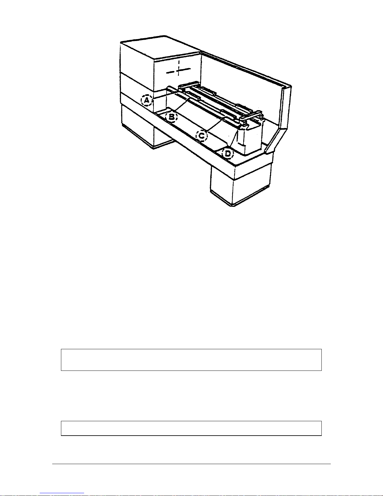
Move the saddle and tailstock to the center of the bed. To take a reading off the level
longitudinally, place the level at each of the four (4) corners of the bedways (Figure 4,
Positions B & C). To take a reading off the level transversely, place it on top of 19 mm
parallels at each end of the bedways (Figure 4, Positions A & D).
Page 16
12
XYZ Machine Tools
ProTURN SLX 1630 ProtoTRAK SLX CNC Safety, Installation, Service & Parts List Manual
i00193
Figure 4
Leveling
2.9.1 SLX 1630
Use the four (4) leveling screws, located at both ends of the base, to adjust the level
of the machine.
For a newly installed machine, check the level once every week. Once the
foundation is rigid enough, then check it once per month.
2.10 Electrical Connection
The SLX 1630 can only be wired for 415 volts, 3-phase electricity.
A 110-volt power source is needed for the pendant and is provided by the
transformer.
DANGER!
Be certain that 415-volt electricity is used only with a machine labeled 415 volts and at the
electric cabinet, in the back of the machine.
The incoming 415-volt power is wired to the machine through the electric cabinet
located on the back of the machine. The wire enters the cabinet through a hole,
from the top of the cabinet. The wires are to be wired into the door breaker. The
main ground wire should be fastened to the breaker mounting bracket with the screw
provided.
DANGER!
The 415 VAC, 3-phase electricity should be wired only by a qualified electrician.
Page 17

13
XYZ Machine Tools
ProTURN SLX 1630 ProtoTRAK SLX CNC Safety, Installation, Service & Parts List Manual
Figure 5
Wiring the 1630
2.10.1 Phase Converters
For those machines that will be run with a phase converter it must be a rotary type
rather than a static phase converter. Rotary phase converters allow for varying loads
in the system. The electrical load on the machine will vary based on the type of cut
taken and the speed of the motor. Static phase converters can only be used on
machines with a non-varying load.
2.11 Mounting the Display Pendant
The 1630 pendant is fixed to a L bracket. The L bracket is attached to a 2nd bracket
that comes mounted to the top of the chip enclosure.
Make the 6 cable connections to the left side of the pendant and cover these cables
with the cable cover provided with the machine.
Page 18

14
XYZ Machine Tools
ProTURN SLX 1630 ProtoTRAK SLX CNC Safety, Installation, Service & Parts List Manual
2.12 Cable Interconnections
All cable interconnections are made at the factory except for those connecting to the
pendant display. There are a total of 6 cables that need to be connected to the
pendant. See Figure 6 for pendant cable connections.
With the main 415 volt power to the machine turned off plug in the connectors that
are bundled on the side of the machine. Each cable fits to only one connector on the
pendant display, on the left side of the pendant. Use the key on the pendant to
match up the connectors with the correct port. The machine ID key and option keys
should be plugged into the port labeled as such. The test port and X and Y
handwheel ports will be left empty during installation. If the customers sets this
machine up on a network, this cable will also need to be plugged in.
Make sure the machine ID key is plugged in, otherwise the machine will not run.
Also make sure there is a hardware (option) key plugged into the parallel port of the
pendant. This key activates any converters or options ordered. The key must be
programmed according to the type of machine it is on and the options ordered.
CAUTION!
Make sure the main 415-volt power switch is disconnected on the back of the electrical cabinet
before plugging in the cables.
Page 19

15
XYZ Machine Tools
ProTURN SLX 1630 ProtoTRAK SLX CNC Safety, Installation, Service & Parts List Manual
Figure 6
Cable Connections
Page 20

16
XYZ Machine Tools
ProTURN SLX 1630 ProtoTRAK SLX CNC Safety, Installation, Service & Parts List Manual
Figure 7
Pendant Cable Connections
Left Side
Page 21

17
XYZ Machine Tools
ProTURN SLX 1630 ProtoTRAK SLX CNC Safety, Installation, Service & Parts List Manual
Figure 8
Pendant, Right Side
2.13 Lubrication System
2.13.1 Headstock
Before turning ON the spindle, check to make sure the headstock oil reservoir is full.
A site glass is located under the spindle cover. If low, fill the site level with Mobil
DTE 24 or equivalent oil through the plug located on the headstock cover.
For the 1630, oil will only be visible on the headstock site glass when the spindle is
running. If oil is not flowing to the site glass when the spindle is on, stop running
Page 22

18
XYZ Machine Tools
ProTURN SLX 1630 ProtoTRAK SLX CNC Safety, Installation, Service & Parts List Manual
the spindle immediately and call for service. Failure to do so may ruin the spindle
bearings.
2.13.2 Automatic Way Lubrication Pump
The 1630 auto lube system provides centralized automatic lubrication for the
carriage, cross slide and ballscrews. The lube pump has a 2-liter reservoir filled with
S.A.E. 30-weight oil.
CAUTION!
Oil that is too heavy and viscous such as 50W or 90W oil can clog oil line tubing. Do not mix detergent
type automotive or multi-purpose oils with the S.A.E. No. 30 lubricating oil used in this application.
The lube pump has electronic memory, which acts as an internal clock to keep track
of the running time of the axis motor. Even when the axis motors are turned off, the
lube pumps internal clock will not reset. The interval between pump cycles is based
on axis motor movement time. Also, every time the control is first turned on, the
lube pump will run for 1 lube cycle as soon as the axis motors are commanded to
run.
2.13.3 Lube Pump Operation
The pumping output can be regulated electronically to control the Interval Time
between pumping cycles, and the Discharge Time of each pumping cycle. The pump
can also be run manually through a key found under service codes. The following
describes the steps used to program the lube pumps Interval and Discharge times.
Setting Interval Time: Service Code 301
Press "Mode", "Set up", "Service Codes", "E" (Lube Pump Setup), Code 301, and
then enter the desired Interval time in minutes.
Setting Discharge Time: Service Code 302
Press "Mode", "Set up", "Service Codes", "E" (Lube Pump Setup), Code 302, and
then enter the desired Discharge time in seconds.
To Manually Pump Oil: Service Code 300
Press "Mode", "Set up", "Service Codes", press "E", and then press Code 300
(Lubrication Pump Switch). The pump will pump oil for the amount of time
programmed in Code 302. The spindle does not need to be turned on.
2.13.4 Factory Default Values
Interval Time - 20 min
Discharge Time - 15 sec
Discharge Pressure - Approximately 690 – 1034 kPa (100-150 PSI)
To adjust the amount of Discharge Pressure displayed on the lube pump gauge,
loosen the jam nut and turn the adjustment screw located on the top right side of
the lube pump while the lube pump is activated. To activate the lube pump use
Service Code 300.
CAUTION!
Failure to properly lubricate the lathe will result in the premature failure of ball screws
and sliding surfaces.
Page 23

19
XYZ Machine Tools
ProTURN SLX 1630 ProtoTRAK SLX CNC Safety, Installation, Service & Parts List Manual
CAUTION!
Failure to manually activate the pump at the beginning of each day, or allowing the Auto
Lube to run dry may cause severe damage to the 1630 lathe way surfaces and ballscrews.
The settings for the lube pump can be viewed by doing the following: press Service
Codes, press “A” (software), press Code 313. This screen lists the values
programmed for the cycle time and discharge time.
Page 24

20
XYZ Machine Tools
ProTURN SLX 1630 ProtoTRAK SLX CNC Safety, Installation, Service & Parts List Manual
3.0 Troubleshooting by Symptom
Electrical and Mechanical maintenance should only be carried out by
trained and experienced machine tool engineers who fully understand the
hazards of working with machine tools.
Use this section to begin the process of resolving a service problem. Each problem type is
described in a few words and then more fully described in an explanatory paragraph.
Following this is a chart that directs in the most logical steps.
3.1 Problems Relating to Machining Results
3.1.1 Poor Finish
Poor finish can be caused by a number of variables including: speeds, feeds,
tooling, machine setup and chatter.
Do the following Service Codes:
Code 33 Software Identification. This is needed if you call Customer Service
Code 12 Feed Forward Constant
Code 127 Measures backlash in the system (not used on Dual Feedback
systems)
Code 128 Enter backlash compensation
Possible Cause
Check This
Inadequate or no Lubrication to
Ballscrews and Way surfaces
Make sure all the Way surfaces are getting proper
lubrication. If not, check to make sure that the lube pump
is functioning properly. Also check for any pinched or
blocked oil lines.
X & Z-axis Drive Trains are loose
Check Repeatability using the Repeatability and Positional
Accuracy procedure. Step by step, carefully inspect the
Drive Train for any looseness. It may be necessary to
disassemble and then reassemble the Drive Train. See
Mechanical Drive Train (X, Z) Section 4.2.
Way surfaces are pocked, scarred, or
excessively worn
Visually check the condition of all the Way surfaces. For
machines that may have excessively worn Way surfaces
you may need to adjust the Gibs in this area. This will
affect performance when using the machine outside of
this area. Check lubrication to affected areas.
Machine set-up problem
Machine’s feet are not equally supporting weight. See
Leveling, Section 2.9.
Tooling problem
Improper tooling, Work piece not properly supported
speeds too fast, Feeds too slow.
See Machine Tool & Setup, Section 4.1.
X gib too tight or loose
See Gib Adjustment, Section 5.2.1.
Loose bearing problem
Looseness in the spindle bearings. Adjust spindle preload.
Ball screw misalignment,
See Mechanical Drive Train (X,Z), Section 4.2. See Spindle
Bearing Preload, Section 5.1.16.
Page 25

21
XYZ Machine Tools
ProTURN SLX 1630 ProtoTRAK SLX CNC Safety, Installation, Service & Parts List Manual
3.1.2 Turning Diameters Out of Round
Parts are not round within .015 mm TIR for SLX 1630. This is best measured by
using a .002 mm dial indicator and mounting to the inside taper of the spindle.
Rotate the spindle and measure the indicator movement.
Do the following service code and procedures:
Possible Cause
Check This
Tooling problem
Improper tooling, workpiece not properly supported.
See Machine Tool & Setup, Section 4.1.
Loose bearing problem
Looseness in the spindle bearings. See Mechanical Drive Train (X, Z),
Section 4.2. Spindle bearing not preloaded correctly. Reseat bearing and
preload. See Spindle Bearing Preload, Section 5.1.16.
3.1.3 Cutting Taper
Parts are considered to be cutting on a taper if there is a difference in diameter of more than
.02 mm over 152.4 mm. This is best measured by using a .002 mm micrometer.
Do the following service code and procedures:
Code 12 Determines the feed forward constant for the axis motors.
Possible Cause
Check This
Machine set-up problem
Machine not leveled properly
See Leveling - Section 2.9.
Tooling problem
Improper tooling; Work piece not properly supported. Use steady rest or
follow rest, reduce overhang from chuck headstock or tailstock.
Looseness in the gib or
misalignment of ball screw
Gib adjustment.
See Gib Adjustment - Section 5.2.1.
See Z Ball screw Alignment - Section 5.1.14.
Loose bearing problem
Looseness in the spindle bearings.
See Mechanical Drive Train (X,Z) - 4.2.
See Spindle Bearing Preload - Section 5.1.16.
Headstock and/or tailstock
not aligned
See Adjust Headstock for Taper - Section 5.1.15.
To adjust tailstock from side to side, adjust gib screw. See Aligning
Tailstock to Spindle Section 5.1.17.
3.1.4 Parts Have Incorrect Dimensions
Parts are being machined with dimensions that are different than those programmed.
Typical accuracy expectations should be:
Parts should be round within .015 mm TIR on both the SLX 1630.
The acceptable measurement of parallelism of spindle axis to carriage movement
is .02 mm over 152.4 mm.
3.1.4.1 Every Part Has the Same Error
Possible Cause
Check This
Programming Error
Programmed dimensions not correct. Check
absolute and incremental values.
Machine & Setup Related
See Machine Tool & Setup - 4.1.
3.1.4.2 Errors are Random or Accumulate in Size over the Part Run
Possible Cause
Check This
Machining Setup
See Machine Tool & Setup - 4.1.
Looseness in the Drive Train, ball nut loose in
yoke, split nut loose, yoke loose
See Mechanical Drive Train (X,Z) - 4.2.
Page 26

22
XYZ Machine Tools
ProTURN SLX 1630 ProtoTRAK SLX CNC Safety, Installation, Service & Parts List Manual
3.1.5 Threading Problems
Threads can be cut with an unlimited number of pitches and up to 10 leads.
To reduce the relief area when threading up to a shoulder the spindle speed should be
reduced as much as possible. The slower the speed of the spindle, the closer the cutting
tool can come to the end of the programmed thread before it pulls out and retracts. If a
nut must be turned all the way up to a shoulder, machine a relief area behind the last
thread.
NOTE: No machine can thread up to a shoulder and instantaneously pull out.
Do the following service codes and procedures:
Code 12 Determines the feed forward constant for the axis motors
Code 133 Spindle encoder test
3.1.5.1 Cross Threading
Threaded parts are cross-threaded after completion of the threading event.
Possible Cause
Check This
Looseness in the Gib
Gib adjustment
See Gib Adjustment - Section 5.2.1.
Looseness in the drive train
The drive train Diagnostics
See Mechanical Drive Train (X,Z) - Section 4.2.
Calibration
See Section 5.2.2 Calibration.
Failure of the spindle encoder
Run service code 133 to check if the encoder
counts.
Replace spindle encoder
See Spindle Encoder replacement - Section
5.1.10.
3.1.5.2 Not Threading
The machine will not cut a thread at all.
Possible Cause
Check This
Spindle speed too fast
Slow down spindle speed.
Failure of the spindle encoder
Run service code 133 to check if the encoder
counts.
Replace spindle encoder
See Spindle Encoder replacement - Section
5.1.10.
Broken or slipping encoder coupling
Check and replace as necessary
3.2 Problems Regarding the Motion of the Machine
3.2.1 Run Away Axis
The axis makes an unwanted move at rapid speed in one direction and faults out.
This is usually caused by an encoder signal being interrupted.
Do the following Service Codes:
Code 33 Software Identification. This is needed if you call Customer Service.
Code 100 Axis open loop test. Used to check the maximum feedrate of an axis
and if the encoders are counting.
Possible Cause
Check This
The home positions or tools are not set
correctly
See the Controls Programming, Operations and Care
manual.
Bad Motor Encoder
See Motor Diagnostics Section 4.4.
Page 27

23
XYZ Machine Tools
ProTURN SLX 1630 ProtoTRAK SLX CNC Safety, Installation, Service & Parts List Manual
3.2.2 Slow Down Axis
The axis slows down and moves at a feedrate that is lower than rapid or than the
programmed feedrate.
Do the following Service Codes:
Code 33 Software Identification. This is needed if you call Customer Service.
Code 100 Axis open loop test. Used to check the maximum feedrate of an axis
and if the encoders are counting.
Code 129 Set's the maximum allowable arc accuracy error. This applies to arcs only.
Possible Cause
Check This
The maximum allowable Arc Accuracy is
set too low.
This value will only slow down the machine during arc moves.
The factory default is set at 0.13 mm. Perform Code 129 to
check or change this value. See Service Codes Section 4.8.
Values lower than 0.13 mm may reduce the feedrate even
more.
Incoming AC voltage is inadequate
Perform Code 100. See Service Codes Section 4.8. and
Electrical Section 4.6.
Inadequate or no Lubrication to
Ballscrews and Way surfaces
Make sure all the Way surfaces are getting proper lubrication.
If not, check to make sure that the lube pump is functioning
properly. Also check for any pinched or blocked oil lines. See
Lubrication Section 2.13.
X-axis Gib is not adjusted properly
Check the adjustment of the X-axis Gibs using the X-axis Gib
adjustment procedures. See section 5.2.1.
Binding in the Drive Train
Check Repeatability using the Repeatability and Positional
Accuracy procedure. Check the torque reading of the Drive
Train. Step by step, carefully inspect the Drive Train for any
binding. It may be necessary to disassemble and then
reassemble the Drive Train. See Mechanical Drive Train (X, Z)
Section 4.2.
Servo Drive failure
See Servo Drive Section 4.5.
Motor failure
See Motor Section 4.4.
3.2.3 Axis Will Not Jog
The system powers up but will not respond to the jog command.
Do the following Service Codes and procedures:
Code 33 Software Identification. This is needed if you call Customer Service.
Code 100 Axis open loop test. Used to check the maximum feedrate of an axis
and if the encoders are counting.
Possible Cause
Check This
Improper Boot-up
Shut down the system and wait 10 seconds before rebooting
E-Stop is pressed in
Check E-Stop. Especially if both axes will not jog
E-Stop reset button
Press the E-Stop reset button on the side of the pendant.
Servo Drive failure
Especially, if only one axis will not jog;
See Servo Driver Section 4.5.
Shorted motor
See Motor Section 4.4.
Poor cable or wiring connections
See Cable Interconnection Section 2.12.
Computer/Pendant failed
See Computer/Pendant diagnostics Section 4.3.
3.2.4 Axis Motor Motion Is Not Smooth
While under motor power, the motion is not smooth. The motion appears to be "rough" or jerky”.
Do the following Service Codes and procedures:
Page 28

24
XYZ Machine Tools
ProTURN SLX 1630 ProtoTRAK SLX CNC Safety, Installation, Service & Parts List Manual
Code 33 Software Identification. This is needed if you call Customer Service.
Code 12 Feed Forward Constant
Code 127 Measure's the backlash in the system
Code 128 Enter backlash compensation
Code 100 Axis open loop test. Used to check the maximum feedrate of an axis
and if the encoders are counting
Possible Cause
Check This
X-axis Gib are not adjusted
properly
Check the adjustment of the X-axis Gib using the X-axis Gib
adjustment procedures, See Section 5.2.1..
Calibration or Backlash problem
Recalibrate the machine. Reset the Backlash. Check
Repeatability and Positional Accuracy. See Calibration &
Backlash Constants section 5.2.2.
Binding in the Drive Train
Check Repeatability using the Repeatability and Positional
Accuracy procedure. Check the torque reading of the Drive
Train. Step by step, carefully inspect the Drive Train for any
binding. It may be necessary to disassemble and then
reassemble the Drive Train. See Mechanical Drive Train (X, Z)
Section 4.2.
3.2.5 Vibration in Motion
While axis is moving there is vibration or noise coming from the X or Z-axis.
Do the following Service Codes and procedures:
Code 12 Feed Forward Constant
Code 127 Measure's the backlash in the system.
Code 128 Enter backlash compensation
Possible Cause
Check This
Too much backlash entered in Code 128.
Recheck the machines backlash. See Section 5.2.2.
Inadequate or no Lubrication to
Ballscrews and Way surfaces
Make sure all the Way surfaces are getting proper lubrication.
If not, check to make sure that the lube pump is functioning
properly. Also check for any pinched or blocked oil lines. See
Lubrication Section 2.13.
X Gib not making good contact.
Pull gibs out and mark with a blue die to check where the gibs
are making contact. It is recommended that the gibs
uniformly contact at least 80% of the surface. See Section
5.2.1 Crosslide gib adjustment.
Binding or looseness in the Drive Train
Check Repeatability using the Repeatability and Positional
Accuracy procedure. Check the torque reading of the Drive
Train. Step by step, carefully inspect the Drive Train for any
binding or looseness. It may be necessary to disassemble and
then reassemble the Drive Train. See Mechanical Drive Train
(X, Z) Section 4.2.
Axis Motor belt too tight.
Loosen belt.
Misalignment of ball screw
See Mechanical Drive Train (X, Z) Section 4.2.
3.2.6 Searching Axis
The ballscrews are slowly turning back and forth when the servos are engaged.
Do the following Service Code and procedures:
Code 12 Sets a feed forward power constant to drive axis motors.
Code 128 Backlash compensation on single feedback machines.
Page 29

25
XYZ Machine Tools
ProTURN SLX 1630 ProtoTRAK SLX CNC Safety, Installation, Service & Parts List Manual
Possible Cause
Check This
Most often causes by excess backlash
compensation
Check physical backlash in system and re-enter in code 128.
Run code 11 on single feedback machines
High feed forward values
Check ball screw torque. Typical values should be between 1.1
– 1.7 N-m.
Excessive friction in the sliding ways
Lubrication, gib adjustments, gib locks.
See Machine Tool & Setup - Section 4.1.
Looseness in the drive train
The drive train of the axis that is searching, especially the
tightness of the drive assembly.
See Mechanical Drive Train (X, Y) - Section 4.2.
3.3 Problems Relating to the Operation of the Control
3.3.1 Display Blanks
The display is completely blank.
Possible Cause
Check This
Screen saver has been activated
Press any key to turn back on. All LED keys on pendant will
blink when the screen saver is on. Press any key to deactivate.
Hitting this key will not activate any feature on the control.
The system has shut down
Turn the power switch off, check the computer/
pendant fuses and cable connections. See Electrical Section 4.6.
Poor cable connection from Computer
Module to LCD (Liquid Crystal Display)
Double-check the connection from the computer module to the
LCD, see Section 5.1.3.
Fuse blown in pendant
Remove fuse and check continuity
Computer/Pendant failed
See Computer/Pendant Section 4.3.
3.3.2 Bad Picture on the Display
The display has strange characters, horizontal bars or other unfamiliar images, or the
display continually rolls.
Possible Cause
Check This
Poor cable connection from Computer
Module to LCD (Liquid Crystal Display)
Check the ribbon cable connection from the LCD screen
to the computer module . See Section 5.1.3.
Computer/Pendant failed
See Computer/Pendant Section 4.3.
3.3.3 Keyboard Lockup
The screen display is normal, but the system will not respond to key presses.
Do the following Service Codes and procedures:
Code 81 press each key on the pendant. The screen will display a keypad
that signifies if a key is working. The pendant will also beep.
Possible Cause
Check This
Voltage drop/spike has occurred
Shut down the system and wait 10 seconds to reboot the
system.
Remote Stop-Go (RSG) switch has a
short (if connected)
Remove the RSG. Turn the system off and then on again.
If the problem goes away and then re-appears when the
RSG is plugged-in, replace the RSG.
Poor cable connections from the
Computer Module to the Distribution
Board and from the Distribution Board
to the Keyboard
Re-seat cable connectors by pulling out and pushing back
in.
Computer/Pendant failed
See Computer/Pendant Section 4.3.
Page 30

26
XYZ Machine Tools
ProTURN SLX 1630 ProtoTRAK SLX CNC Safety, Installation, Service & Parts List Manual
3.3.4 Fault X or Z
The program run or jogging operation is interrupted with a Fault Message on the
display.
Do the following Service Codes and procedures:
Code 33 Software Identification. This is needed if you call Customer Service.
Code 12 Feed Forward Constant.
Code 100 Axis open loop test. Used to check the maximum feedrate of an axis
and if the encoders are counting.
Possible Cause
Check This
Servo cables at pendant switched around.
Make sure during an installation the X and Z servo
cables at the pendant are in the correct ports.
X-axis Gibs are adjusted extremely tight
Check the adjustment of the X-axis Gibs using the X
Gib adjustment procedures. See X-axis Gib
Adjustments Section 5.2.1.
Excessive friction in the slideways
See Machine Tool & Setup Section 4.1.
Binding or looseness in the Drive Train
See Mechanical Drive Train (X, Z) Section 4.2.
Incoming electrical power
Incoming voltage. See Electrical Section 2.10.
Servo Drive failure
See Servo Driver - Section 4.5.
Motor failure
See Motor diagnostics, Section 4.4.
Computer/Pendant failure
See Computer/Pendant diagnostics, Section 4.3.
3.3.5 Problems Reading the Floppy Disk; Programs Not Saved
Properly
The floppy drive will not read or write programs from a disk.
Possible Cause
Check This
Improper Boot-up
Shut down the system and wait 10 seconds before
rebooting.
Floppy Disk failure
The Floppy Disk may be bad. See if the Floppy Disk
can be read by a Personal Computer. Does the green
light on the floppy drive come on when you access the
disk? If so, power is getting to the floppy drive. If
not check connections of floppy drive inside the
computer module. See Computer/Pendant Section 4.3
for more information.
Floppy Disk full
Put the Floppy Disk into a Personal Computer to see
how many bytes remain.
3.3.6 System Will Not Turn On
Nothing happens when the switch is turned on.
Possible Cause
Check This
110 V line is not plugged in
Check incoming 110 V power source to electrical cabinet
Pendant On/Off switch is Off.
Check the Pendant On/Off switch
Fuse blown in pendant or electrical
cabinet
Remove fuses and check continuity.
Transformer output
Check 110 V Transformer output
Computer/Pendant has failed
See Computer/Pendant diagnostics Section 4.3.
3.3.7 System Will Not Boot-Up
The system does not boot-up when the switch is turned on.
Page 31

27
XYZ Machine Tools
ProTURN SLX 1630 ProtoTRAK SLX CNC Safety, Installation, Service & Parts List Manual
Flash Drive failure
When the Computer Module starts the boot-up process,
look at the 8th line on the Display Screen. If the Mother
Board of the Computer Module is communicating with
the Flash Drive you will see "Detecting IDE Primary
Master…Scan Disk SDCFB-256". If the Mother Board of
the Computer Module is not communicating with the
Flash Drive you will see "Detecting IDE Primary Master …
None".
Also, check the wiring connection between the Flash
Drive and the Mother Board. See Computer/Pendant
diagnostics Section 4.3.
Computer/Pendant has failed
See Computer/Pendant diagnostics Section 4.3.
Disk in drive A
Verify that there is no disk inserted in drive A.
System Bios
Verify the system bios is set correctly.
3.3.8 System Reboots by Itself
During operation, the screen suddenly blanks and then shows that the system has
begun the boot-up sequence.
Possible Cause
Check This
Incoming 415 VAC is too high, too low
or not present
Using a Voltmeter, check the incoming 415 VAC to the machine.
See Electrical Section 4.6.
Poor wiring and cable connections
Check for any loose wiring.
Computer/Pendant failed
See Computer/Pendant diagnostics Section 4.3.
Transformer output
Check 110 V Transformer output
3.3.9 System Shuts Off
During operation, the system shuts off and will not turn back on.
Possible Cause
Check This
Fuse blown in pendant
Remove fuse and check continuity
Incoming 415 VAC is too high, too low or not
present
Using a Voltmeter, check the incoming 415 VAC to the
machine. See Electrical Section 4.6.
Poor wiring and cable connections
Check for any loose wiring.
Flash disk failure
Remove and reseat the flash disk. The flash disk is inside of
the computer module. Please see section 5.1.4.
Transformer output
Check 110 V Transformer output
Computer/Pendant has failed
See Computer/Pendant diagnostics Section 4.3.
3.3.10 Will Not Hold Calibration
The control will not hold calibration. Go to the "Configuration Values" screen and
write down the calibration values for the motor encoders (Encoder) and the position
feedback encoders (Scales). Recalibrate the system and see if the values change.
Turn the system off and on and see if the values are held.
Do the following service codes and procedures:
Code 33 Software Identification. This is needed if you call Customer Service.
Code 313 Configuration Values
Code 123 Calibration Mode
Possible Cause
Check This
Not saving Calibration values
Replace Computer/Pendant module.
See Computer/Pendant Diagnostics Section 4.3.
Page 32

28
XYZ Machine Tools
ProTURN SLX 1630 ProtoTRAK SLX CNC Safety, Installation, Service & Parts List Manual
If calibration factors are being saved, but the measurements are not repeating or are not
accurate:
See Measurements Are Not Repeating
See Measurements Are Not Accurate
3.3.11 E-Stop Error
The E-Stop turns the power off to the axis and spindle motors. The 1630 has an estop on the front of the pendant and a green E-stop reset button on the side of the
pendant. (See figures 6 & 8)
For the axis motors this is done by stopping 110V power from reaching
the cable breakout box through the use of a relay in the pendant. The
AC E-stop out connector on the pendant should not have 110 volts
coming out of it when the E-stop is pressed.
The AC drive power is turned off by a contact relay (K1), located on the
power module. The contact relay (K1) is turned off by the dual channel
relay (safety relay), which is controlled by the E-stop on the pendant.
The E-stop LED on the spindle control module will be on when the e-stop
is in the out position. The LED will turn off when the E-stop is depressed.
(See figure 11)
Once power reaches the cable breakout box it distributes power to the
axis motors, auxiliary functions. If power does not reach the cable
breakout box then none of these functions will work.
If the E-Stop button is depressed, and no message is displayed on the screen, then
either the E-Stop button, pendant, spindle control module, cables from pendant to
spindle control module, or cables from spindle control module to dual channel relay
(safety relay) is at fault.
Possible Cause
Check This
E-Stop reset button
Press the E-Stop reset button on the side of the
pendant.
Faulty E-Stop switch
Check the cable connections from the computer
module to the E-Stop switch. Check the E-Stop switch
for functionality.
Bad pendant
Does 110 V power come out of the cable breakout box
power cord on the pendant? If yes and the screen
has an E-stop message then replace the pendant.
Poor cable connection
Check spindle control cable connection at the pendant
and spindle control box.
E-Stop jumper
Verify the E-Stop jumper in the electrical box on the
spindle control module is correct.
3.4 Problem with the Measurements
3.4.1 X and Z-Axis Measurements Do Not Repeat
With a dial indicator mounted to the bottom of the spindle, touch off a fixed surface
either in the X or Z-axis direction and then set the DRO equal to 0. Crank away
several inches and then touch off again at the same place. If the reading has not
returned to 0 on the DRO, zero the display and repeat the procedure. If the
measurement does not repeat, you have a repeatability problem that must be
resolved.
Page 33

29
XYZ Machine Tools
ProTURN SLX 1630 ProtoTRAK SLX CNC Safety, Installation, Service & Parts List Manual
Test for accumulative error by moving the axis a number of times to see if the error
gradually grows by a small amount. If the error abruptly changes by a large amount it may
be caused by a bad encoder.
Expected repeatability numbers should be 0.01 mm or less.
Possible Cause
Check This
Machine Tool & Setup problem
Check for any looseness in the setup. See Machine Tool
& Setup Section 4.1.
X and Z-axis Gibs are loose
Check the adjustment of the X-axis Gib using the X-axis
Gib adjustment procedures. See section 5.2.1.
X and Z-axis Drive Trains are loose
Check Repeatability using the Repeatability and Positional
Accuracy procedure. Step by step, carefully inspect the
Drive Train for any looseness. It may be necessary to
disassemble and then reassemble the Drive Train. See
Mechanical Drive Train (X, Z) Section 4.2.
Encoder Disk or Reader Head on
motor are loose
Swap the motor in question with a known good motor.
For example, swap the X-axis motor with the Z-axis
motor. If the symptom stays with the motor in question,
then replace the motor. If not, then the motor is not at
fault and something else is causing the problem.
3.4.2 X and Z-Axis Measurements Are Not Accurate
Measurements repeat, but with a dial indicator mounted to the spindle, traversing the
length of a gage block or some other measurement standard, the measurement is
not accurate.
Note: If your part has incorrect dimensions, see Parts Have Incorrect Dimensions, Section
3.1.4.
Note: First check for repeatability of the DRO: With a dial indicator touch off a fixed surface
either in the X or Z-axis direction and set the DRO equal to 0. Crank away several inches and
touch off again at the same place. If the reading has not returned to 0 on the DRO, zero the
display and repeat the procedure. If the measurement does not repeat, you have a
repeatability problem that must be resolved before the accuracy problem can be resolved. See
Measurements That Do Not Repeat, Section 3.4.1.
Possible Cause
Do This
The Calibration is incorrect
Recalibrate the machine.
See Calibration & Backlash Constants
Incorrect backlash values
If the machine does not repeat bi-directionally check the
backlash on the axis in question. See Calibration and
Backlash Constant Section 5.2.2.
3.4.3 The DRO Is Not Counting
The DRO for one axis is not counting when an axis is moved. Often times if this is
the case the axis will fault. See section on faulting.
Do the following Service Codes:
Code 33 Software Identification. This is needed if you call Customer Service.
Code 100 Axis open loop test. Used to check the maximum feedrate of an axis
and if the encoders are counting.
Code 132 Electronic handwheel test.
Code 131 Manual Encoder Test.
Page 34

30
XYZ Machine Tools
ProTURN SLX 1630 ProtoTRAK SLX CNC Safety, Installation, Service & Parts List Manual
Possible Cause
Check This
Electronic handwheel failure
The Z handwheel should count 2.54 mm per revolution in both
directions in fine mode and 10.2 mm per revolution in course
mode. The X handwheel should count 0.51 mm per revolution in
both directions in fine mode and 2.54 mm per revolution in
course mode.
Servo driver failure
See Servo driver Section 4.5.
Motor Encoder not counting
See Motor diagnostics (not applicable with Glass Scale option)
Computer/Pendant failure
See Computer/Pendant diagnostics section 4.3.
3.4.4 X and Z-Axis DRO Counting in Wrong Direction
The DRO is counting in the wrong direction.
The positive directions for each axis are:
X-axis – cross slide moves toward the operator
Z-axis – carriage moves toward tailstock
Do the following service code and procedures:
Code 33 Software Identification. This is needed if you call Customer Service.
Code 313 Check the line that specifies the product.
If the product does not match the machine then the machine ID key will need to be replaced.
3.4.5 X and Z-Axis Electric Handwheels Turn in Wrong
Direction
The Electric Handwheels turn in the wrong direction.
The positive directions for each Electric Handwheel are:
X-axis - Electric Handwheel turns counterclockwise.
Z-axis - Electric Handwheel turns clockwise.
Do the following service code and procedures:
Code 308 Reverse X-axis Handwheel Direction.
Code 310 Reverse Z-axis Handwheel Direction.
3.5 Problems with the Machine Tool
3.5.1 Spindle Stalls or Turns-Off During Machining
During machining, the spindle turns off and loses power. First check incoming
voltage and connections.
Possible Cause
Check This
Machine Tool and Setup problem
Check the type of material being cut, type and size of cutting tool,
RPM, and Feed rate. Also check the condition of the cutter to
verify that the cutter is not dull. See Machine Tool & Setup Section
4.1.
Motor drive Belt is slipping
Check the alignment, condition, and tension of the Drive Belt.
Cut more than the machine is capable
Check speeds, feeds and depth of cut
Page 35

31
XYZ Machine Tools
ProTURN SLX 1630 ProtoTRAK SLX CNC Safety, Installation, Service & Parts List Manual
3.5.2 Spindle Motor Hums or Will Not Run
The spindle motor makes a constant humming noise during operation or will not turn
on.
Possible Cause
Check This
Wrong voltage
Check the 415V voltage to the machine
Poor wiring connections
Check all the wiring connections to the electric’s box.
Defective cable connections
Check all cable connections
Spindle Motor is bad
Check the resistance of the Spindle Motor windings on the Spindle
Motor between L1 & L2, L2 & L3, and L1 & L3, using an Ohmmeter.
The resistance should range from ".7 to 1.8 Ohm". If the Ohmmeter
reads "0 Ohms" or "OL", then replace Spindle Motor. Next, check the
resistance between L1 & Ground, L2 & Ground, and L3 & Ground,
using an Ohmmeter. The resistance should read "OL". If not then
replace Spindle Motor.
3.5.3 Spindle Runs Backwards
The spindle motor runs in the opposite direction.
Possible Cause
Check This
3-Phase wires backwards
Need to switch any 2 of the 3 wires either coming out of the
Spindle Drive (T1, T2, and T3) or going into the Spindle Motor (U,
V, and W). Caution: Be sure to shut off all power to the machine
before attempting to switch any wires.
3.5.4 Excess Gearbox Noise
Gearbox noise is louder than normal. Run the lathe at the gear where the noise is
most noticeable. Remove the gearbox lid and try to isolate where the noise is
coming from.
Possible Cause
Check This
Insufficient amount of oil in headstock
Check site glass to make sure oil is at sufficient level.
Spindle bearing not being lubricated
properly, worn bearing
Remove top lid and check to make sure oil is
overflowing freely to the spindle bearings.
Spindle preload loose
Tighten spindle preload on bearing. The spindle
preload should be approximately 1.1 – 1.7 N-m.
3.5.5 Headstock is Leaking Oil
A Form-A-Gasket sealant should be use to seal any leaking areas. Make sure the
sealant fills the leaking area thoroughly. Sealant must cure for 24 hours for best
results.
3.5.5.1 Leaking Oil from Rear of Gearbox
Possible Cause
Check This
Leaking from behind belt drive pulley
Replace shaft seal - o-rings or gaskets.
Oil leaking from behind the spindle
encoder.
Remove spindle encoder and pinion shaft cover.
Check the seal.
Oil leaking from the rear bearing
assembly.
Make sure the spindle shaft cover is mounted
correctly, if so remove the cover and check the o-ring.
Page 36

32
XYZ Machine Tools
ProTURN SLX 1630 ProtoTRAK SLX CNC Safety, Installation, Service & Parts List Manual
3.5.5.2 Leaking Oil From Front of Gearbox
Possible Cause
Check This
Oil leaking between cover and gearbox
Remove gearbox cover. Thoroughly clean cover & top
of gearbox. Replace gasket and reassemble.
3.5.6 Tailstock Barrel is Stiff
The tailstock barrel is stiff or not smooth moving through its travel. The tailstock
barrel subassembly jams inside the tailstock.
Possible Cause
Check This
Misalignment of tailstock housing
Realign bearing housing and tailstock screw. Loosen
screw support and realign.
Too much grease.
Disassemble and remove excess grease.
Vernier Dial is binding or rubbing on
screw support.
Remove dial and machine off a couple of thousandths
or shim.
Page 37

33
XYZ Machine Tools
ProTURN SLX 1630 ProtoTRAK SLX CNC Safety, Installation, Service & Parts List Manual
4.0 Diagnostics
Electrical and Mechanical maintenance should only be carried out by
trained and experienced machine tool engineers who fully understand the
hazards of working with machine tools.
This section explains the diagnostic procedures used to isolate service problems.
4.1 The Machine Tool & Set-Up
4.1.1 Leveling
Leveling is one of the most important aspects of setting up the machine properly.
Improper leveling can lead to a variety of machining problems.
The machine should be level to within .02 mm longitudinally and .01 mm
transversely. See Leveling Procedures, Section 2.9.
4.1.2 A Special Word About The X Gib
The X gib is vital to the performance of your lathe.
Gibs should be:
flat
free of twist
free of burrs
free of blockages in the oil passages and channels
Defective or scarred gibs must be replaced. Shimming of gibs will not yield
acceptable results.
It is good machining practice to avoid the use of shop air to clean the chips off a
machine. This risks blowing chips into the sliding way surfaces and compromising
the performance of the machine.
See Gib Adjustments, Section 5.2.1.
4.1.3 Lubrication
Lubrication is one of the single, most important maintenance issues and plays a key
role in assuring the performance and durability of the lathe. At the beginning of each
day manually supply oil to the way surfaces by doing service code 300.
Lack of lubrication can lead to a variety of problems with your machine motion due to
increased friction in the sliding ways. This increased friction may lead to part
inaccuracies and decreased life expectancies of your ballscrews and way surfaces.
Lack of lubrication in the headstock can lead to increased wear of the gear train as
well as premature wearing or failure of the spindle bearings. For the 1630, oil will be
flowing only when the spindle is on.
4.1.4 Machining Set-Up
The machining set-up itself is always something that can greatly influence the
performance of the lathe. The following are some things to keep in mind.
Page 38

34
XYZ Machine Tools
ProTURN SLX 1630 ProtoTRAK SLX CNC Safety, Installation, Service & Parts List Manual
Problems With
Can Contribute To:
Feed and Speeds (spindle rpm)
See below
Poor finish
Excessive speeds and feeds can break cutting tools
or wear out too fast.
Tooling
Using the wrong cutter for an application
Poor finish
Parts incorrect
Cutting too deep
Part dimensions incorrect
Driving and cutting forces cause deflections, since no
material is totally rigid
No coolant
Poor finish, decrease the life of the cutter
The following is a list of common machining problems and some possible solutions.
Problem
Check or Try This
Poor surface finish
Dull tool
Reduce feedrate
Increase spindle speed
Use a higher rake angle tool
Make sure tool is not dull or chipped
Use proper grade of cutting tool
Use coolant
Check to see if tools are on the centerline
Long workpieces out of round
Use a follow or steady rest
Excessive chatter
Tool bit improperly ground or not on center
Avoid extreme negative rake inserts
Tool overhang too great, tool deflection
Improper feeds and speeds
X gib loose. See
Gib Adjustment, Section 5.2.1
Work improperly supported
Machine tool out of level - See
Leveling Procedures,
Section 2.9.
4.1.4.1 Spindle Speeds
Spindle speeds are influenced by a number of variables:
Material
Rigidity of the Machine Setup
Coolant
Insert, geometry and material of insert
Depth of cut
4.1.4.2 Feedrates
Factors that affect feedrates:
Depth of cut
Design or type of insert
Sharpness of the insert
Workpiece material
Type of finish or accuracy required
Page 39

35
XYZ Machine Tools
ProTURN SLX 1630 ProtoTRAK SLX CNC Safety, Installation, Service & Parts List Manual
4.2 The Mechanical Drive Train (X,Z)
Indications:
Troubleshooting instructions indicate that the drive train is potentially the
problem and other, more easily checked, variables have been exhausted.
Roughness, looseness, tightness or jamming movement in the carriage or cross slide.
Carriage walk-up due to Z ball screw misalignment.
1. Check for machine considerations, especially X gib adjustments and leveling. See
Gib Adjustments, Section 5.2.1.
2. Do the following special service codes:
Code 12 - this is a procedure that helps the control adjust to the friction
characteristics unique to the machine. Write down the resulting values from
the display. If your problem is control related, check to see if this procedure
has resolved the problem.
3. The torque required to manually turn the X and Z-axis ballscrews should be
between 10-15 in-lbs. These values should be consistent in both directions and
along all areas of the axis travel. Values that differ from that of above may
correspond to misaligned ball screws.
The following steps take you in a logical sequence through the assemblies. If the
step doesn’t isolate or resolve the problem, it will be necessary to disassemble
the indicated item and move to the next step.
1. Ensure that the screws that hold the bearing housing in place are not loose.
2. Ensure that the Clamp Nut is secured. The following applies to the clamp nut:
When loosening, make sure to back out the 10-32 screw from the clamp nut.
3. When tightening, snug the 10-32 screw to keep the clamp nut from spreading,
after applying the appropriate torque (50 ft lbs), tighten the 10-32 screw.
4. Take out the angular contact bearings in the X & Z-axis and inspect them. They
should roll smoothly and be lightly greased. If not, replace them. The Z-axis has
2 bearing housings. The tailstock bearing housing only contains 1 ball bearing.
NOTE: The bearing housing and spacer rings are matched sets - keep them together.
5. With the motor and drives removed, inspect the ball screw, ball nut and yoke for
the potential problems shown in the chart below.
CAUTION!
Unlike a leadscrew, do not unscrew the ball screw from its nut. This will destroy the ball screw!
Page 40

36
XYZ Machine Tools
ProTURN SLX 1630 ProtoTRAK SLX CNC Safety, Installation, Service & Parts List Manual
Potential Problem:
Check By:
Bad ball screw
Visual inspection of the ball nut - if the nylon seal is broken or deformed, if
contamination has visibly entered the ball nut or if balls are out of the ball nut,
replace the ball screw.
Cranking the ball screw through a significant part of its travel. If it jams, feel loose or
has rough spots, replace the ball screw.
Dial indicator movement when indicating on the end of the ballscrew indicates
backlash between the ball screw and ball nut.
Ball nut not
tightened to the
yoke
Inspection for space between the head of the bolt and the ball nut i.e. the retaining
bolt has bottomed out in its thread and is not securing the ball nut to the yoke
properly.
Yoke loose in the
carriage
Inspection for any motion of the yoke or looseness in the Yoke mounting screws.
Oil lines sheared
Visual inspection.
Oil line blockage
Pump the oil and ensure that it flows evenly to the ways, ball screws and cross-slide.
Z Ball screws not
aligned properly
Manually turn the ball screw through the length of its travel. Pay particular attention
to the movement near the headstock, the middle and the tailstock.
NOTE: Ball screws are inspected throughout their entire travel for backlash and consistent torque. A
ball screw should be good for millions of mm of travel if installed properly. Do not be too quick to
replace a ball screw if there is insufficient indication that it is bad; this will just be a costly delay to
resolving the real problem.
See: Z Ball Screw Removal, Section 5.1.13
X Ball Screw Removal, Section 5.1.11
Aligning Z Ball Screw, Section 5.1.14
4.3 Computer/Pendant Diagnostics
The pendant consists of 2 separate modules: the computer module and the pendant
enclosure minus the computer module.
In general, the pendant/computer module is best diagnosed by eliminating all other
possible alternatives. The following table lists some problems and what these
problems can lead to.
Possible problems
Can lead to
Poor cable connections
There are 6 cable connections to the left side of the pendant. Make
sure all cables are properly fastened.
Pendant locks up
Press the E-stop button and see if lock up clears if not then do the
following:
Turn the pendant off, wait at least 30 seconds, and turn it back on and
check to see if the malfunction has been reset.
No voltage to RSG port
RSG will not work – should be 5 DC volts present
Check with a voltmeter.
Low voltage to flash drive or
slave board.
Can cause the system to lock up and the flash drive to act abnormally.
Check voltage to the RSG port with a voltmeter. It should be 4.8 DC
volts and above. Lower values than this can cause problems.
Flash disk failure
If the flash disk fails, the system will not boot up or operate. It will
need to be replaced. All programs and machine configurations will be
lost. Make sure to back up your flash drive from time to time.
Only the flash disk module will need to be replaced.
Floppy disk failure
Will not allow user to save or pull up programs from a floppy disk. Can
the floppy drive format a disk? See Section 4.3.
Page 41

37
XYZ Machine Tools
ProTURN SLX 1630 ProtoTRAK SLX CNC Safety, Installation, Service & Parts List Manual
LCD backlight burns out
Check all cable connections to LCD, distribution board and computer
module. Make sure the power is turned off before doing so.
Faulty E-stop switch
It can be stuck open or closed (pressed). If it is stuck closed the
pendant will need to be replaced because the user will have no way to
get rid of the message. If it is open it will allow the machine to still
operate but it will be unsafe for the user. The pendant will still need to
be replaced. The E-Stop reset button may need to be pressed.
Overlay failure (keys on
pendant)
Certain buttons on overlay do not work. Do code 81 to verify each key
beeps.
Low voltage to pendant or
current spikes
1 amp fuse in pendant blows. Pendant will not turn on.
Slave board not functioning
Machine will not run. If under Code 33 it says “demo,” it means the
slave board is not functioning.
4.3.1 Checking Floppy Drive by Formatting a Disk
1. Find a new disk and install in floppy drive.
2. Install keyboard into middle port.
3. Press CTRL ESC to get to start menu.
4. Press R for run.
5. Type Format a: - press enter.
6. If the format works your disk drive is working. If format does not work, reboot
control and see if it now works. If it does not work replace the computer
module.
7. Press ALT ESC to get back to PT4 software.
4.4 Motor Diagnostics
The Motor subsystem is comprised of 2 parts: The Motor Encoder and the Motor.
The motors are powered by 110 VAC voltage. The servo driver is also an integral
part of servo system, which is discussed in detail in the next section.
WARNING!
Do not work with the motors unless the power is disconnected from the machine. The motors
are run by 110 VAC. There is possibility of death by electrocution!
Rarely do both the X and Z motor/servo systems fail at the same time and in the same
way. So, if your problem is occurring on both axes, its source is probably somewhere
else.
4.4.1 Cable Connections
Check the motor cable connections on the cable breakout box. Verify there are no pushed
in pins on the connector.
4.4.2 To Check the Motor Encoders
If the motor encoder inside the motor has failed or is not reading the machine will fault
out on that axis. Do the following to verify this problem:
Run Service Code 100 or 131. This will display on the DRO if the motor encoder is
counting. If this axis does not count, the encoder is not counting. This means either the
encoder or the cable is the problem. Visually check the cable for any problems. If the
encoder has failed the motor must be replaced.
Page 42

38
XYZ Machine Tools
ProTURN SLX 1630 ProtoTRAK SLX CNC Safety, Installation, Service & Parts List Manual
4.4.3 Encoder Counts to Pendant
Before replacing the motor due to a bad motor encoder it is a good idea to check the
cables that take those signals back to the pendant. If these signals are not getting
back to the pendant then the axis will fault. Check the following cable connections.
Umbilical #1 and #2 at the cable breakout box
Umbilical #1 and #2 at the pendant
Umbilical #1 carries the X-axis signals and Umbilical #2 carries the Z-axis signal.
4.4.4 Moving Problem from One Axis to Another
Another way to troubleshoot a problem with a particular axis is to swap parts from 1
axis to another to see if the problem moves. If the problem moves then that
component is faulty. See the example below.
Symptom – X Axis will not move and faults
This particular problem can happen because of any of following reasons: bad motor,
servo driver, power cable, or computer module. In some cases it is not always
obvious which component is causing the problem. This example will help us pinpoint
the problem through a trial and error process.
Let’s assume we have narrowed it down to the servo or electrical systems and the Xaxis has no problems. Lets also assume it is not an obvious problem like a loose
connection. This particular example was done on a machine with motor encoders
only.
Swap these components
Results
Physically switch the X and Z
motors
Has problem moved to Z-axis? If yes, replace motor. If no,
the motor is not the problem.
4.5 Servo Drivers
The two (2) servo drivers are located in the electrical cabinet.
Indications:
Problems moving just one axis. The axis faults out on the screen.
Servo Types:
X is a light duty driver
Z is a heavy duty driver
Objective:
Isolate the problem to the particular Servo Driver
Steps:
1. Turn off and unplug the system.
2. Physically swap the servo module from the axis that is not working to one that is.
WARNING!
Do not work with the Servo Driver unless the power is disconnected from the machine. There is
possibility of death by electrocution!
Page 43

39
XYZ Machine Tools
ProTURN SLX 1630 ProtoTRAK SLX CNC Safety, Installation, Service & Parts List Manual
Note: To avoid pulling the wires out of the connector, use the loop to pull the connector from
the Servo Driver.
If the problem moves to the other axis and clears up from the original axis, replace
the Servo Driver.
WARNING!
Do not work run each axis very long when swapping servo’s. They are not rated to run each
motor for long periods of time.
4.6 Electrical
4.6.1 Checking A/C Voltage
This procedure tests for the 115V power for the control.
Use a Voltmeter, reading A/C volts
Acceptable range is 110V to 130V
Note: systems running consistently close to the high or low values may have problems when
normal voltage fluctuations push the voltage out of the acceptable range.
The system is shipped out assuming the customers shop has 415 V power. If the
transformer secondary tap is set on 115 volts. Measure the voltage coming out of the
transformer by placing the voltmeter across the 115 V and 0 V taps. If this measurement is
above 120 volts then move the tap from 115 V to 110 V. If the reading is low, 110 V or
below, then change the tap from 115 V to 124 V. Input power to the machine that is 430 V
or above will cause the 110 voltage to be high and voltage that is 405 V or below typically
causes 110 voltage to be low.
4.6.2 Checking Fuses
There are 11 fuses that make up the system on the 1630. There are 2 fuses in the
pendant, 3 fuses on the spindle control module and 6 fuses on the power module.
To check fuses:
1. Use a Volt/Ohmmeter; select “OHM” or “”.
2. Remove the fuse completely from the pendant display or electrical box.
3. Place a lead of the meter on each end of the fuse.
A good fuse reads 0 (zero) or close to it.
A bad fuse reads Open or Infinity or OL (overload).
Page 44

40
XYZ Machine Tools
ProTURN SLX 1630 ProtoTRAK SLX CNC Safety, Installation, Service & Parts List Manual
4.6.3 Main Electrical Box
Only qualified electrical engineers should work in this box.
The electrical box is made up of the following main components:
1. AC drive – used to control the spindle motor.
2. 2 braking resistors – used to brake the spindle motor. To verify the resistors are
good, measure the resistance across B1 and B2 of the AC drive. It should read 32
ohms when both resistors are good and 64 ohms if 1 resistor is bad and one is
good. Values lower or higher than this could mean one or both resistors are bad.
3. Spindle Control Module – used to control spindle related functions, indexer
option, and the remote e-stop. The spindle control module has (1) 5-amp fuse,
(1) 3-amp fuse and (1) 12-amp fuse. The spindle control module also has (6)
110 V outlets that supply power to the pendant, spindle, lube pump, indexer,
lamp, and the door fan.
4. Cable breakout box – used to send encoder information to the pendant and
provide power to the motors.
5. Servo drivers – servo drivers for the X and Z-axis motors.
6. Power Module - The purpose of the power module is to fuse and distribute 415 V
3 phase power to the drive module assembly. L1 and L2 lines from the 3 phase
415 VAC is used for the primary side of the transformer to produce 110 V singlephase power to the spindle control module. The power module has (3) 25 amp
fuses to protect the entire system. It also has (2) 4 amp and (1) 2 amp
secondary fuses. The power module also has a ground bar where all the panels
are grounded and a dual channel relay (safety relay) that is controlled by the Estop and E-stop reset button on the pendant.
Page 45

41
XYZ Machine Tools
ProTURN SLX 1630 ProtoTRAK SLX CNC Safety, Installation, Service & Parts List Manual
Figure 10
Electrical Box Parts
Page 46

42
XYZ Machine Tools
ProTURN SLX 1630 ProtoTRAK SLX CNC Safety, Installation, Service & Parts List Manual
Electrical Box Parts List
Item
P/N
DESCRIPTION
Qty
1
24039
SHEETMETAL-SLX-DRIVE MODULE
0 2 24042
MODULE-SPINDLE CONTROL
1 3 24999-2
CABINET ASSY-PT4 -SL-CABLE BREAKOUT BOX-AUXILARY FUNCTIONS
1 4 22287-euro
AC DRIVE PROGRAMMED
1 5 20201
SERVO DRIVER ASSY
1 6 22283-2-3-30
WIREWAY- TYPE G LIGHT GRAY
1 7 22283-1-3-30
WIREWAY- TYPE G LIGHT GRAY
1
12
1/4-20X3/8 31Z
SCREW-PH-PHIL-EXT SEMS-STL-ZINC
7
13
10-32X3/8 31Z
SCREW-PH-PHIL-EXT SEMS-STL-ZINC
12
14
6-32X5/8 31B
SCREW-PH-PHIL-EXT SEMS-STL-BO
8
15
20327-3
SERVO DRIVER ASSY - 4050D
1
16
20689
CABLE ASSY-L2 SERVO DRIVERS TO CONN PCB
1
17
24181
CABLE ASSY-LATHE CBB TO SPINDLE CONTROL
1
21
22392-1-30
COVER- WIREWAY- TYPE G
1
22
22392-2-30
COVER- WIREWAY- TYPE G
1
23
22778
LABEL-REVISION LEVEL
1
24
22779-21
LABEL-
1
25
21786-4
ADAPTER ASSY - SLX E-STOP JUMPER
1
30
24360-SLX 1630
AC DRIVE PROGRAMMED - SLX 1630
1
31
24144
SHEETMETAL-SLX-POWER MODULE
1
32
21891
FILTER- HIGH POWER
1
33
21258-2
TRANSFORMER - 1.2kVA
1
34
21753-2
GROUND BAR-SLX 1630
1
35
22283-3/4-2-12
WIREWAY- TYPE G LIGHT GRAY
2
36
22392-3/4-12
COVER- WIREWAY- TYPE G
2
37
23037
DIODE-BRIDGE RECTIFIER-HIGH CURRENT-25 WATT
1
38
24426-1
RAIL-DIN
1
39
22557-1
TERMINAL BLOCK - 6mm BLOCK
5
40
23036
FUSE HOLDER-32 AMP-690V
6
41
22892-3
CONTACTOR -
1
42
22891
RELAY-DUAL CHANNEL
1
43
23152-2
FUSE-500 VOLT-
1
44
23152-25
FUSE-500 VOLT-
3
45
23152-4
FUSE-500 VOLT-
2
46
M6-1.0X6 10Z
SCREW-PH-PHIL-STL-ZINC
18
47
M5-0.8X16 10Z
SCREW-PH-PHIL-STL-ZINC
3
48
M5-0.8X6 10Z
SCREW-PH-PHIL-STL-ZINC
9
49
24299
TERMINAL BLOCK
1
50
21455-2
CABLE ASSY - SX AUX SAFETY I/O
1
51
24429
CABLE ASSY - 1630 SLX POWER CABLE
1
52
24424
TERMINAL BLOCK - JUMPER
1
53
24423
SUPPRESSOR - NOISE
1
54
M6 70Z
WASHER-FLAT USS-STL-ZINC
8
55
M6 73B
WASHER-SPLIT LOCK-STL-BO
8
i01187
Page 47

43
XYZ Machine Tools
ProTURN SLX 1630 ProtoTRAK SLX CNC Safety, Installation, Service & Parts List Manual
4.6.3.1 Spindle Control Module LED Segments
1st 10 LED Segment
1. LED labeled GEAR 4 – not used.
2. LED labeled GEAR 3 – not used.
3. LED labeled GEAR 2 –The 1630 does not have a gear switch.
4. LED labeled GEAR 1 This light should be off when it is in high gear or
neutral. This light is not on for the 1630 because it has no gears.
5. LED labeled SPD-FAULT – this light will be on whenever the AC drive is in a
fault condition, which includes an E-stop message from the pendant.
6. LED labeled SPD-RUN – this light should be on whenever the spindle is on.
7. LED labeled SPD-ENABLE – this light should be on whenever you are in DRO,
tool setup and RUN mode.
8. LED labeled LUBE PUMP – this light should be on whenever the lube pump is
on and off when it is not on.
LED’s 9 and 10 are not used.
2nd 10 LED Segment
1. LED labeled E-STOP OUT – this light should be on whenever the E-stop is in
the out position. When the E-stop is pressed, this light should go off.
2. LED labeled OFF RELAY – this light should be on whenever the off button on
the pendant is pressed.
3. LED labeled TAP MODE – light should be on whenever you are not tapping.
Light will be off when in the tap event.
4. LED labeled TAP REVERSE – this light will be on when the spindle changes
direction at the bottom of the hole on a tap event and back off after the
spindle changes direction once outside of the tap event.
5. LED labeled REV-RELAY – this light should be on whenever the spindle is
running in reverse.
6. LED labeled FWD-RELAY – this light should be on whenever the spindle is
running in forward.
7. LED labeled LI-BIT 1 – this LED should be on whenever the lathe indexer is
at any odd tool position.
8. LED labeled LI-BIT 2 – this LED should be on whenever the lathe indexer is
at tool positions 2, 3, 6 or 7.
LED’s 9 and 10 are not used.
3rd 10 LED Segment
1. LED labeled LI-BIT 3 – this LED should be on whenever the lathe indexer is
at tool positions 4, 5, 6 or 7. For the 4 tool indexer, if you program tools 5,
6, 7 or 8, the indexer will physically move to tools 1, 2, 3 or 4 respectively.
For example, if you program tool 7, LED light LI BIT 3 should be on.
2. LED labeled LI-BIT 4 – this LED should be on whenever the lathe indexer is
at tool position 8.
3. LED labeled REMOTE E-STOP – this LED should be on whenever the remote
e-stop or pendant e-stop is in the out position.
4. LED labeled OIL PRESSURE – not used.
Page 48

44
XYZ Machine Tools
ProTURN SLX 1630 ProtoTRAK SLX CNC Safety, Installation, Service & Parts List Manual
5. LED labeled LI-PROX SWITCH – this LED should be on whenever the lathe
indexer is locked in position.
6. LED labeled LI-AIR PRESSURE – this LED should be on whenever the air
pressure for the lathe indexer is incorrect.
7. LED labeled 24VDC OK – this LED should be on whenever the 24 volts for the
lathe indexer is not present.
8. LED labeled 5VDC OK – this LED should be on whenever the 5 volts for the
lathe indexer is not present.
LED’s 9 and 10 are not used.
4th 10 LED Segment
1. LED labeled FWD-KEY – this LED should be on whenever the FWD key on the
pendant is being pressed.
2. LED labeled OFF-KEY – this LED should be on whenever the OFF key on the
pendant is being pressed.
3. LED labeled REV-KEY – this LED should be on whenever the REV key on the
pendant is being pressed.
4. LED labeled LI-SEL 4 – is not used and should never be on.
5. LED labeled LI-SEL 3 – this LED should be on whenever a tool position on
the Dorian indexer is commanded which would increment the tool by 4
positions or decrement the tool by 1, 2, 3 or 4 positions. For increment, the
Dorian indexer is rotating in a CCW path when facing the turret. May not
apply to the 4-tool indexer.
6. LED labeled LI-SEL 2 – this LED should be on whenever a tool position on
the Dorian indexer is commanded which would increment the tool by 1, 2 or
4 positions or decrement the tool by 1or 4 positions. May not apply to the 4tool indexer.
7. LED labeled LI-SEL 1 – this LED should be on whenever a tool position on
the Dorian indexer is commanded which would increment the tool by 1, 3 or
4 positions or decrement the tool by 2 or 4 positions. May not apply to the 4tool indexer.
8. LED labeled CHUCK GUARD – not used
9. LED labeled FWD-REVERSE – not used
LED 10 is not used.
Page 49

45
XYZ Machine Tools
ProTURN SLX 1630 ProtoTRAK SLX CNC Safety, Installation, Service & Parts List Manual
Figure 11
Spindle Control Module LED’s
Page 50

46
XYZ Machine Tools
ProTURN SLX 1630 ProtoTRAK SLX CNC Safety, Installation, Service & Parts List Manual
4.6.4 Cable Breakout Box Connections
The list below describes what takes place through each connection. Power reaches
the cable breakout box through AC IN from the pendant. From there power is
distributed through the system.
Umbilical #1 & Umbilical #2 Ports (To Pendant) - The lathes have (2)
motor encoder signals, which are communicated between the Encoder module
and the Pendant by use of (2) Umbilical cables. The X signal is communicated
through umbilical #1 and the Z motor signal is transferred through umbilical #2.
Apron Port - Communication for X & Z-Handwheel and jogstick logic signals
between the Pendant and the cable breakout box.
and Z- servos.
X & Z - Motor Ports - are used to receive power from the servo and distribute
it to the motors.
X & Z-Motor Encoder Ports - These ports are used to receive logic signals
from each of the X & Z-Motor Encoders.
Spindle Encoder Port - The port is used to receive logic signals from the
spindle encoder, when it is engaged for a threading routine.
Logic to Servo (PWM) - This port is used to keep continuous feedback
between the servos and the cable breakout box.
110 VAC Outlet - The outlet is for powering up the coolant pump. Beside the
outlet is an LED light signifying power is reaching the pump when it is active, and
a fuse to protect the pump.
E-Stop and Spindle Out Port - used to disable power to the spindle motor
when the E-Stop is activate.
4.6.5 Cable Connections
The lathe machines use 7+ cables to communicate between systems. It is often the
case that what appears to be the failure of an electrical component is actually
attributable to a poor connection.
Indications:
Control problems, chronic or intermittent.
Motor problems.
Measurement problems.
Explanation:
1. Turn off and
unplug
the system from the wall.
WARNING!
Do not plug and unplug connectors with the system power on. This may cause damage to the
connector board and harm to the technician.
2. Visually inspect the connections for excessive debris, moisture, or obvious
damage.
3. Carefully clean any chips away from the connectors.
4. One-by-one, take out each connector and then plug them back in. Do the same
at the computer/display.
5. Make sure the screws are tightened on each of the connectors.
Page 51

47
XYZ Machine Tools
ProTURN SLX 1630 ProtoTRAK SLX CNC Safety, Installation, Service & Parts List Manual
4.7 Door Interlock Switch
The 1630 uses door interlock switches to verify to the control that the doors are
closed in various modes of operation. This switch is wired normally open but is
forced closed when the doors are closed during CNC run mode. The switches are
wired in series to a 9 pin DB connector. There should be continuity between pins 1
and 6 when the switches are forced closed and no continuity when the switches are
in the open position.
4.8 Service Codes
Service codes are broken down into the 4 following categories: software, machine
setup, diagnostics, and user options/defaults.
All Service Codes are accessed in the SET-UP Mode by pressing the soft key for
“SERV CODES”. The service codes can be located within the headings listed on the
main screen. Press the heading you want to access the code in question. If you
know code # you want press the CODE # softkey and it will take you directly to the
code in question. Press CODE #, enter the number you want, press SET.
4.8.1 Software Codes
The following codes pertain to software functions in the control. To get to any of
these codes go to Service Codes, press “A” and press the code you wish to view.
Note - Write the values down for Code 33 or Code 313. These values will be valuable
for troubleshooting.
4.8.1.1 CODE 33: Software ID
Code 33 is the software identification procedure. The two types of software in the
control include:
Software Version - the version of the system you have installed.
Firmware Version - the version of firmware software that is responsible for
control to servo interface.
Operating System Version – displays the version of the operating system.
4.8.1.2 CODE 37: RS232 Baud Rate
This code sets the baud rate for RS232 applications. The recommended baud rate is 9600.
The following baud rates can be chosen: 4800, 9600, 19200, 38400, 57600, 115200.
4.8.1.3 CODE 141: Load Configuration file from floppy “A” drive
This code allows you to load your configuration file from the floppy disk to your hard
drive. The configuration file consists of items such as calibration and backlash
constants. This code is used when a computer module or hard drive has been
replaced.
4.8.1.4 CODE 142: Save Configuration file to floppy “A” drive
This code allows you to save your configuration file to a floppy disk. The
configuration file consists of items such as calibration and backlash constants. This
code is used when a computer module or hard drive needs to be replaced. This
stores the configuration file from the hard drive to the floppy disk. It is a good idea
to do this code after the machine is initially setup so these values can be saved and
used in the future. If the computer or hard drive fails, then you will not have the
Page 52

48
XYZ Machine Tools
ProTURN SLX 1630 ProtoTRAK SLX CNC Safety, Installation, Service & Parts List Manual
ability to save the configuration file and the machine will need to be re-setup when
the computer or hard drive is replaced.
Note: All machines will have a copy of the configuration file in the back of the electric’s
cabinet.
4.8.1.5 CODE 313: Display Configuration File
This code displays the configuration file. This file contains pertinent information
about the machine. The file will look similar to the following. If the file becomes
corrupt you can load default values by pressing the F4 softkey.
Product = 1440S/1745S (displays machine ID key)
Motor encoder calibration constants 610.0712 1143.8921
(These numbers above are typical numbers for the calibration constants)
Arc accuracy – 0.13
Code 128 X=0.13 Z=0.04
Code 12 (+) X=000005 Z=000006
(-) X=000005 Z=000006
Code 100 (+) X=352.7 Z=325.2
(-) X=350.1 Z=333.1
4.8.1.6 CODE 316: Update Master Software
Load upgrade disk in floppy drive and press this service code. New software will
automatically download and control will reboot. Please perform alignment routine
afterwards.
4.8.1.7 CODE 317: Update Slave Software
Load upgrade disk in floppy drive and press this service code. New software will
automatically download and control will reboot. Please perform alignment routine
afterwards.
4.8.1.8 CODE 318: Activate Converters or Options
See programming and operating manual.
4.8.2 Machine Set-up Codes
The following codes are used primarily when setting up a new machine. To get to
any of these codes go to Service Codes, press “B” and press the code you wish to
view.
4.8.2.1 CODE 12: Feed Forward Constant
The Code 12 procedure helps the control “learn” the friction characteristics of the
machine by sending a graduated series of motor signals and observing the results.
The process takes less than 30 seconds to run. It is both a diagnostic routine that
displays values, and a routine that sets the parameters of the control for the
particular machine.
The Code 12 is used for diagnosing and resolving:
Problems with machine motion.
Machined parts come out bad – especially poor finish.
Note: Code 12 routine will set the parameters for the particular machine and its particular
situation. If the machine changes its friction characteristic, the Feed Forward Constant
should change too, or the system will not servo properly. Whenever gibs are adjusted or a
heavy workpiece has been added to the table, you should run a Code 12. When the heavy
workpiece is removed, Code 12 should be run again.
Page 53

49
XYZ Machine Tools
ProTURN SLX 1630 ProtoTRAK SLX CNC Safety, Installation, Service & Parts List Manual
1. Position the table and addle in the center of travel. Note: You will lose your DRO
position reference.
2. Go into the Service Codes and input the Code 12.
3. Press Auto
4. The system will run the routine automatically and then display values on the
position readout.
Explanation
Typical values should be between 4.04 and 11.11 are considered normal for each
axis. Higher values indicate excessive friction in the system. Lower values indicate a
loose system and may mean a gib adjustment is necessary. Value 4.04 means the
friction is a factor of 4 in one direction, and 4 in the other direction. The values
should be within 3 or 4 of each other in both directions. A value of 6.08 would still
be considered normal.
On S products, do not equate Code 12 values to torque on ballscrew. Measure
friction in system with an N-m torque wrench.
The feed forward gain can be adjusted manually by pressing the manual button.
Choose the axis you would like to change and then enter values in the positive and
negative direction to adjust. Adjusting the gain can help solve circularity problems.
Default values can be set by pressing the Reset button. The manual feature should
only be used in extreme cases where the AUTO routine did not solve the problem.
Manual adjusts above 12 may lead to servo related problems.
4.8.2.2 CODE 100: Axis Open Loop Test
Code 100 procedure is used to diagnose problems with the configuration of the
system, the encoders and incoming A/C voltage.
IMPORTANT -- SAFETY NOTICE
During this procedure the designated axis will be given a command to move at maximum
speed for 1 second in the direction you choose. Avoid crashes by starting with the crossslide and saddle centered. MAKE SURE THAT NO ONE IS STANDING IN THE WAY OF THE
CROSS-SLIDE OR SADDLE!
Note: You will lose the DRO reference position.
This procedure is to be run for each axis that is servo-driven, and for both the plus
and minus direction for each axis.
1. Center the cross-slide and saddle.
2. On the Pendant display, go into the Service Codes and input the Code 100.
3. The conversation line will say: “SELECT AXIS”. Input the axis. Either X or Z.
4. In the conversation line it will say “WHICH DIRECTION? PLUS”.
If you want to run in the plus direction, press INC SET.
If you want to run in the minus direction, press +/-, then INC SET.
5. In the conversation line it will say “PRESS GO”. Press Go after you are sure that
the machine will not crash in the direction and axis that you have specified.
6. Afterward the screen will display values next to the DRO position axes.
Page 54

50
XYZ Machine Tools
ProTURN SLX 1630 ProtoTRAK SLX CNC Safety, Installation, Service & Parts List Manual
Your input
Display
Data displayed.
X +
X
Motor encoder reading
Z
Nothing (should be 0)
Feedrate
the maximum feedrate attained
Your input
X
Motor encoder reading
X -
Z
Nothing (should be 0)
Feedrate
the maximum feedrate attained
Your input
X
Nothing (should be 0 )
Z +
Z
motor encoder reading
Feedrate
the maximum feedrate attained
Your input
X
Nothing (should be 0 )
Z -
Z
motor encoder reading
Feedrate
the maximum feedrate attained
Interpretation of the resulting values displayed:
The values for the encoder displays should be in the range of 76 mm to 127 mm.
If the motor encoder value is not within specification it may be the problem. If
the encoder is not reading then it will need to be replaced.
The feedrate should be a minimum of 180 ipm for X, and 120 ipm for Z. Shops with
higher voltages will see higher values.
If the feedrate is less than 4572 mm/min (180 ipm) and inconsistent in both
directions, check the incoming AC voltage and mechanics of the drive train.
4.8.2.3 CODE 123: Calibration
See Section 5.22 for a further explanation of this code.
4.8.2.4 CODE 127 - Set X or Z Backlash Constant
See Section 5.22 for a further explanation of this code.
4.8.2.5 CODE 128: Input Backlash Constant
Code 128 allows you to enter the backlash values for each axis. It displays the value
after it enters. This code is only used on machines with motor encoders only.
4.8.2.7 Code 308: Reverse X Hand Wheel Direction
This service code reverses the direction of the X hand wheel.
4.8.2.8 Code 310: Reverse Z Hand Wheel Direction
This service code reverses the direction of the Z hand wheel.
Page 55

51
XYZ Machine Tools
ProTURN SLX 1630 ProtoTRAK SLX CNC Safety, Installation, Service & Parts List Manual
4.8.3 Diagnostic Codes
The following codes are used primarily when diagnosing a problem with the machine. To
get to any of these codes go to Service Codes, press “C” and press the code you wish to
view.
4.8.3.1 Code 54: Program Continuous Run
This Code runs a program continuously without stopping for tool change commands.
It is helpful in running a long period to identify an intermittent problem.
1. Prepare a program as you normally would.
2. Press MODE, SET UP, “C”, Code 54, INC SET. The program run will start automatically.
3. Press STOP to stop, and GO to continue.
4.8.3.2 Code 81: Keyboard Test
This code is used to check if the keyboard is functioning correctly. It allows you to
test each key on the pendant individually. When you press the keys, the
corresponding box for that key will highlight on the screen. The pendant will also
beep, indicating that the key is working correctly. If one of the keys does not work
the pendant assembly may need to be replaced. If none of the keys are working
chances are that the computer module will need to be replaced.
4.8.3.3 Code 131: Manual DRO
A manual diagnostic routine to check the motor encoder and table encoders. Turn
the X hand wheel to display the encoder readings. This code will display the actual
DRO counts and the raw encoder counts before the calibration and backlash factors
have been factors into the counts.
4.8.3.4 Code 132 - Electronic Hand Wheel Test
Turn the X or Z-axis electronic hand wheel. The display should show movement as
the hand wheel is being turned. There should be no skipping and it should count
smoothly while the hand wheel is being turned. One revolution of hand wheel should
read 10.2 mm for Z and 2.54 mm for X in course mode and 2.54 mm for Z and 0.51
mm for X in fine mode.
4.8.3.5 Code 133 – Spindle Encoder Test
Turn the spindle or run the spindle at low RPM’s. The display should show the
counts from the spindle encoder. It should count to 360 on the Z display and then
reset. Each time it resets it displays the number in the X display area.
4.8.3.6 Code 314: Toggle Test Lights ‘ON’ in Status Line
This code toggles on and off 2 test lights that appear in status line. The top light
signifies if the master software is working. If functioning it should flash a green light.
The bottom light signifies if the slave firmware is functioning. It will appear orange
in run mode when it is processing information. Pressing the mode key will change
this orange box to black. The orange box will also change to black when the
program you are running reaches the 3rd event from the end of the program. If the
firmware is locked up no keys will work. This code is useful for diagnosing
intermittent problems with the control locking up.
4.8.3.7 Code 319: Error Log
This code when turned on captures the commands that were sent to the servo
system. It includes items such as positioning commands, errors, stop and go
Page 56

52
XYZ Machine Tools
ProTURN SLX 1630 ProtoTRAK SLX CNC Safety, Installation, Service & Parts List Manual
commands, etc. It may be helpful for identifying problems between programmed
commands and executed commands. To turn on the error log press the F6 softkey.
The page forward and backward keys allow you to scroll through the file one page at
a time. The data forward and data backward keys allow you to scroll through the file
one line at a time. The data bottom key takes you to the bottom of the file and then
changes to data top which will take you back to the top. The file will capture data
until the file reaches a size of approximately 600 Kb. At this time the file is saved to
a backup file and the original file is cleared and data is once again captured. Once
again as the file reaches a size of 600 Kb it copies over the previous backup file.
From here the user can save the file to the floppy drive by pressing the F8 softkey.
Once this is done it prompts you for which file you want to save to disk. The F1 key
saves the current file to disk and the F2 key saves the backup file to disk. To clear
the files press the F7 softkey.
4.8.3.8 Code 324: Toggle Simulation Mode
Simulation Mode allows the control to run a program without actually moving the
table. It is helpful in diagnosing Computer/display problems.
4.8.3.9 Code 326: Error Message Display
Error Message Display is used to describes error messages.
4.8.4 Operator Defaults/Options Codes
The following codes allow the user to set programming defaults or turn features on
or off. To get to any of these codes go to Service Codes, press “D” and press the
code you wish to view.
4.8.4.1 Code 66: Default Metric
This code causes the control to turn on in the metric mode.
4.8.4.2 Code 67: Default English
This code causes the control to turn on in the English mode.
4.8.4.3 Code 79: Beeper On
This turns on the beeper to the control keys.
4.8.4.4 Code 80: Beeper Off
This turns off the beeper to the control keys.
4.8.4.5 Code 129: Arc Accuracy
When the SL control operates at high feedrates it may create small part machining
errors as it goes around sharp corners. This exists on all CNC’s and is commonly
called a “following error.” The control is factory preset to allow a maximum following
error of 0.13 mm. The feedrate will automatically be adjusted around sharp corners
so as to not violate this limit. This code only applies to arcs that are programmed
and ones that are created in the tool path to generate the shape you want. This
code will not make a difference on mill moves.
You may adjust the maximum following error to a value as small as .003 mm.
However, the smaller the value, the slower the feedrate around corners.
To input a new Following Error use the following procedure:
Follow the instructions on the screen and input the Following Error value (from .003
to .3 mm) and press INC SET.
Page 57

53
XYZ Machine Tools
ProTURN SLX 1630 ProtoTRAK SLX CNC Safety, Installation, Service & Parts List Manual
5.0 Procedures for Replacements & Maintenance
Electrical and Mechanical maintenance should only be carried out by
trained and experienced machine tool engineers who fully
understand the hazards of working with machine tools.
5.1 Replacements
5.1.1 Motor Replacement
1. Turn off power to the machine.
2. Each motor is mounted by the use of (4) ¼-20 screws. Be careful not to over
tighten these bolts and strip the threads.
5.1.2 Servo Driver Replacement
WARNING!
Do not work with the Servo Drivers unless the power is disconnected from the machine. The
servo drivers are run by 110 VAC. There is possibility of death by electrocution!
The Servo Driver for each axis is located inside the electric cabinet.
DANGER!
Always engage (push in) the Emergency Stop switch, turn the ProtoTRAK SLX Control off, and
disconnect the servo driver cable at the cable breakout box.
1. Press in the Emergency Stop.
2. Remove the servo driver from the panel, inside the electric cabinet.
3. Remove the 4 cap screws that hold the servo driver and its heat sink plate to the panel.
4. Disconnect the cable connector from the servo driver.
5. Reinstall the new servo driver with its heat sink plate.
5.1.3 Computer Module and LCD/Enclosure Replacement
1. Turn power off to the machine and control.
2. Unplug all the connectors on the pendant arm side of the pendant.
3. Remove the pendant from the pendant arm by removing the (4) ¼-20 x 3/4” SCHS that
secure it in place.
4. Place the pendant assembly on a clean and secured table with the display pointing away
from you.
5. Remove the (6) 10-32 x 3/8” Pan Phillips Head Screws and (4) 10-32 x 3/8” FHCS
securing the computer module to the LCD/enclosure.
6. Pull the computer module a few inches and stop. Pulling the computer module too far
will damage the ribbon cables.
7. Now reach from the top and remove the 37-pin LCD cable, 37-pin distribution cable and
the 9-pin E/Stop cables. The cables are to stay with the computer module.
8. Now slide the module about ½ way out of the LCD/enclosure.
9. Remove the ground wire from the LCD/enclosure side.
Page 58

54
XYZ Machine Tools
ProTURN SLX 1630 ProtoTRAK SLX CNC Safety, Installation, Service & Parts List Manual
10. Lastly, slide the unit completely out of the LCD/enclosure.
11. Replace computer module or LCD/enclosure.
12. Follow the instructions in reverse order when reinstalling the new computer module or
LCD/enclosure.
13. Make sure that all connectors are properly seated before fastening the unit back in place.
Note: if the flash drive is functional, you may want to remove the flash disk and install it in the new
flash drive.
Page 59

55
XYZ Machine Tools
ProTURN SLX 1630 ProtoTRAK SLX CNC Safety, Installation, Service & Parts List Manual
Figure 12 (Figure shown with inner sheet metal removed)
Computer Module & LCD/Enclosure Replacement
Page 60

56
XYZ Machine Tools
ProTURN SLX 1630 ProtoTRAK SLX CNC Safety, Installation, Service & Parts List Manual
5.1.4 System Flash Disk Replacement (See Figure 13)
1. From the control, go to SETUP, SERV CODES, SECTION A, and then code 142
and save your Configuration file (calibration values, etc.) on a floppy disk. There
is a disk in the electric’s cabinet for this purpose. Label this disk as “Backup
Configuration” and store it for later use.
2. Turn power off to the machine and control.
3. Unplug all the connectors on the pendant arm side of the pendant.
4. Remove the pendant from the pendant arm by removing the (4) ¼-20 x 3/4”
SCHS that secure it in place.
5. Place the pendant assembly on a clean and secured table with the display
pointing away from you.
6. Remove the (6) 10-32 x 3/8” Pan Phillips Head Screws and (4) 10-32 x 3/8” FHCS
securing the computer module to the LCD/enclosure.
7. Pull the computer module a few millimeters and stop. Pulling the computer
module too far will damage the ribbon cables.
8. Remove the defective System Flash Disk (located on the back side of the mother
board) by pushing the eject button on the flash drive.
9. Firmly insert the replacement System Flash Disk into the drive, making sure that
the label with the serial number is pointing towards the motherboard.
10. Secure the computer module back to the LCD/enclosure by following the
instructions in reverse order.
11. Make sure that all connectors are properly seated before fastening the unit back
in place.
12. Turn power on to the machine and control.
13. When the system boots, you may get a message stating that the system cannot
find your configuration file. Press NO if asked to load defaults.
14. Update the System Software by inserting the PT4SX update disk into the floppy
drive. Go to service codes 316 and 317 found in section A. Update the master
and slave software.
15. Restore the Configuration file saved on your backup configuration disk with
service code 141 found in section A of the service code section.
CAUTION!
It is a good idea to back up your flash disk from time to time via a network or floppy disk. If
your flash disk needs to be replaced you will loose all of your programs. See your programming
manual for instruction on how to do this.
Page 61

57
XYZ Machine Tools
ProTURN SLX 1630 ProtoTRAK SLX CNC Safety, Installation, Service & Parts List Manual
Figure 13 (Figure shown with inner sheet metal removed)
Flash Disk Replacement
Page 62

58
XYZ Machine Tools
ProTURN SLX 1630 ProtoTRAK SLX CNC Safety, Installation, Service & Parts List Manual
5.1.5 Cable Routing on Machine
Whenever you replace a cable or reroute a cable it is very important to keep the power
cables and logic cables separated from each other. The power cables consist of the (2)
110-volt motor cables and (2) 110-volt power cables for the pendant, and a coolant
pump or solenoid power cable. The logic cables are used to carry encoder signals
between the cable breakout box and computer module. Mixing of the power and logic
cables may cause noise from the power cables to interrupt the signals in the logic cables.
This can lead to intermittent axis faults or repeatability problems.
5.1.6 Electronic Handwheels & Jogstick
There are 2 electronic handwheels on the lathes and 1 jogstick to move the carriage
quickly into position. Each unit is replaced as an assembly. Disconnect the handwheels
and jogstick from the apron cable. (See Figure 41, Section 7)
5.1.7 Cable Routing in Electrics Box
Whenever you replace a cable or reroute a cable it is very important to keep the power
cables and logic cables separated from each other. The power cables consist of the (2)
110 volt servo motor cables and (4) 110-volt power cables for the pendant, spindle motor
fan, coolant pump, and lube pump. The logic cables are used to carry signals between
modules, handwheels, encoders, etc. Mixing of the power and logic cables may cause
noise from the power cables to interrupt the signals in the logic cables. This can lead to
intermittent axis faults or repeatability problems.
5.1.8 Spindle Drive Belt Replacement (See Figure 14)
The spindle drive motor is located inside the base pedestal, underneath the headstock
gearbox. Access is gained by opening the upper door on the headstock and removing
the lower access panel on the pedestal. When removing the belt, loosen nut “G” and
advance nut “H” until the belt has sufficient slack to be removed from the pulleys.
When installing the belt, retract nut “H” and tighten nut “G”. Initially, tension the belt
such that there is no slippage when the lathe is started at its maximum speed.
Belt tension should be checked frequently during the first days of operation, and
periodically thereafter. Keep the pulleys and belt clean and free of any foreign material
to ensure long life and maximum traction.
Page 63

59
XYZ Machine Tools
ProTURN SLX 1630 ProtoTRAK SLX CNC Safety, Installation, Service & Parts List Manual
Figure 14
Spindle Drive Belt/Motor Mounting
5.1.9 Spindle Motor Removal (see Figure 14)
1. Unplug or remove all power from the lathe.
2. Remove the motor belt.
3. Mark and remove motor electrical leads.
4. Because of the weight and size of the spindle motor, and the restricted working
space, extreme caution should be used in sliding the motor from its mounting
plate.
5. Loosen the belt tension. See section above.
6. The motor is secured with four screws to a flange plate.
5.1.10 Spindle Encoder Replacement
1. Unplug or remove all power from the lathe.
2. Open the rear spindle cover to gain access to the encoder.
3. Loosen setscrews on flexible coupling and the bolts that hold the encoder on.
4. Slide the encoder off.
5. The spindle encoder assembly is only available as a complete unit. Do not
disassemble.
5.1.11 X-Axis Ball Screw Removal (see Figure 15)
1. Unplug or remove all power from the lathe.
2. Access to the X-axis ball screw is gained by removing the access guard and
removing the X-axis motor cover.
3. Remove the motor.
4. Remove all items on the right end of the ball screw.
5. Unbolt the ballscrew nut from the yoke.
6. The X ball screw is removed through the exposed hole when the cross slide is
removed.
Page 64

60
XYZ Machine Tools
ProTURN SLX 1630 ProtoTRAK SLX CNC Safety, Installation, Service & Parts List Manual
Figure 15
SLX 1630 X-Axis Drive Train
Page 65

61
XYZ Machine Tools
ProTURN SLX 1630 ProtoTRAK SLX CNC Safety, Installation, Service & Parts List Manual
SLX 1630 X-Axis Drive Train Parts List
Item
Parts No.
Description
Material
Specification
Q'ty 1
Hexagon Socket Screw
M6x16L
6 2 24698
Wiper - Crosslide (front)
Rubber
25-0220
1
3
25-0215
Cross Slide
FC25
1 4
Socket Button Head Screw
M6x10L
2 5 25-0739
Front Cover Plate
SS41
1
6 Socket Head Cap Screw
M8x16L
1 7
O-Ring P7
1 8
Socket Head Cap Screw
M8x30L
4
9
25-0212
Seat - Nut
FC25
1
10
Socket Button Head Screw
M6x10L
4
11
24699
Wiper - Crosslide (Rear)
Rubber
25-0221
1
12
20984
Ballscrew - X Axis
SCM415
25-0211
1
13
25-0218
Rear Cover Plate
SS41
1
14
25-0209
Clamping Block
FC20
1
15
25-0206
Bumper
PU
2
16
25-0205
Cam
SS41
2
17
Socket Head Cap Screw
M8x35L
4
18
Cover - Bearing
7204AVH
1
19
23930
Bearing Set - Angular Contact Ball
7204BECBP
2
20
15885
Spacer
S45C
1
21
SLX 16300
Bearing Housing
S45C
1
22
16314
Nut - Clamp
S45C
j19x16UNF
1
23
24A-0216
Cone Clamping Element
Brass
1
24
98481A090
Woodruff Key
#3(1/8"x1/2")
1
25
16983-1
Pulley-ballscrew
S45C
5Mx44T
1
26
W02
Lock Washer
W02(j15)
1
27
NT02
Lock Nut
N02(j15x32UNF)
1
28
Socket Head Cap Screw
10-32x3/4"
1
29
25-0219
Rear Cover Plate
SS41
1
30
Socket Head Cap Screw
M8x30L
4
31
450-5M-15
Belt-X Axis
5M-450-15
1
32
Set Screw M5x6L
3
33
Pulley
Aluminum
5Mx16T
1
34
Lock Ring
SS41
1
35
25-0208
Plate - Cover - X Axis Motor
SS41
1
36
25-0207
Plate - Motor
SS41
1
37
24316
Motor - X Axis Servo
1
38
24-0315
Clampiing Block (Rear)
FC25
1
39
50-0325-00
Screw - Adjusting
S30C
4
40
Socket Head Cap Screw
M8x25L
10
41
23337-28
Gib - Z Axis
FC25
24-0313
2
42
24-0314
Clamping Block (Front)
FC25
1
43
25-0712
Cover - Protection
SS41
1
44
24-0311
Apron
FC25
1
45
Socket Head Cap Screw
M8x30L
4
46
Socket Head Cap Screw
M6x30L
4
47
23337-72
Wiper - Bedway (Right, Rear)
Rubber
24-0337
1
48
Crossed Recessed Head Screw
M6x16L
12
Page 66

62
XYZ Machine Tools
ProTURN SLX 1630 ProtoTRAK SLX CNC Safety, Installation, Service & Parts List Manual
49
23337-73
Wiper - Bedway (Left, Rear)
Rubber
24-0336
1
50
Hexagon Socket Screw
M5x6L
8
57
22446
Bearing - self aligning
2204E-2RS1TN9
1
58
N04
Lock Nut
S45C
N04(j20x16UNF)
1
59
W04
Lock Washer
W04
1
60
16295-1
Bearing Housing
FC20
1
61
Socket Head Cap Screw
M12x50L
4
62
Washer - Spring
M12
4
63
Socket Head Cap Screw
M6x20L
2
64
25-0321
Bumper
Rubber
2
65
25-0320
Cam
SS41
1
66
Socket Head Cap Screw
M8x70L
2
67
23337-82
Wiper - Bedway (Right, Front)
Rubber
25-0335
1
68
24714
Gib - X Axis
FC30
25-0217
1
69
17-0321-00
Screw - Adjusting
S30C
2
70
Socket Head Cap Screw
M8x25L
4
71
25-0201
Saddle
FC25
1
72
Socket Head Cap Screw
M12x65L
4
73
23337-81
Wiper - Bedway (Left, Front)
Rubber
25-0334
1
74
24704
Ballscrew - Z Axis
SCM415
25-0310
1
75
Cover - Bearing
AVH7205
1
76
23940
Bearing Set - Angular Contact Ball
7205 BECBP
2
77
SLX 16302
Spacer
S45C
1
78
24A-0308
Seat - Bearing
S45C
1
79
Socket Head Cap Screw
M8x25L
4
80
16452
Nut - Clamp
S45C
j19x16UNF
1
81
24A-0216
Cone Clamping Element
Brass
1
82
16983-1
Pulley-ballscrew
Aluminum
1
83
98481A090
Woodruff Key
#3 (1/8"x1/2")
1
84
W01
Lock Washer
W01 (j12)
1
85
N01
Lock Nut
N01 (j12x32UNF)
1
86
Set Screw M5x10L
3
87
Socket Head Cap Screw
10-32x3/4"
1
88
Socket Head Cap Screw
M12x35L
4
89
400-5M-15
Belt - Z Axis
400-5M-15
1
90
Pulley
Aluminum
5M-30T
1
91
Socket Head Cap Screw
1/4-20UNCx30L
4
92
Washer - Flat
1/4"
4
93
Washer -Spring
1/4"
4
94
77USDA-0304
Base - Motor - Z Axis
FC30
1
95
16775-1
Motor - Z Axis Servo
1
96
25-0223
Cover Plate (Front)
SS41
1
I01153.xls
Page 67

63
XYZ Machine Tools
ProTURN SLX 1630 ProtoTRAK SLX CNC Safety, Installation, Service & Parts List Manual
5.1.12 Installing Angular Contact Bearings (See Figure 16)
1. On the inner race of the angular contact bearings, the thin walls face each other.
2. When tightening the clamp nut, first engage a few threads. Then lightly tighten
the locking screw slowly, so that when you slowly thread the lock nut inwards
you can feel some contact between the two threads.
3. Once the clamp nut is completely threaded inwards you will need to use a torque
wrench to apply 68 N-m. of torque, properly seating the bearings.
4. Completely thread in the locking screw to prevent the lock nut from unthreading.
Figure 16
Angular Contact Bearings
Page 68

64
XYZ Machine Tools
ProTURN SLX 1630 ProtoTRAK SLX CNC Safety, Installation, Service & Parts List Manual
5.1.13 Z-Axis Ball Screw Removal (see Figure 17)
1. Unplug or remove all power from the lathe.
2. The Z-axis ball screw is attached to the lathe in three places:
a. The left end where the Z-axis motor, the pulley, the clamp and the pair of
angular contact bearings are mounted.
b. Behind the apron assembly where the ball nut is attached to the yoke and
the oil line is located.
c. The right end where the floating bearing is located.
3. Access to the left end is gained by removing the sheet metal panel below the
headstock nameplate.
4. Access to the ball nut and the yoke is gained by removing the apron assembly.
5. For easy assess to the ball screw, remove the ball screw cover.
5.1.14 Align Z-Axis Ball Screw Assembly (See Figure 17)
1. Recheck machine level. Adjust as necessary.
2. Move carriage to middle of travel.
3. Loosen headstock bearing housing and mounting bracket and loosen tailstock
bearing housing.
4. Snug but do not tighten the yoke mounting bolts.
5. Move the ball screw manually and move the carriage to the tail stock end.
6. Tighten the yoke, this will align it vertically.
7. Tighten the tailstock bearing housing.
8. Loosen the yoke and retighten to realign ball horizontally.
9. Using a socket extension, move the carriage to the headstock.
10. Tighten the Z-axis housing.
11. Tighten the bearing housing.
12. Turn the ball screw manually with the socket extension and move the carriage to
the middle of the travel.
13. Loosen the yoke mounting bolts to readjust the apron plate after the bearings
have been tightened.
14. Retighten the yoke.
15. Move the ball screw manually and move the carriage through the entire length
of the Z-axis. Pay special attention to the areas near the headstock, tailstock,
and in the middle of the travel. If there is any binding or rough spots, the
alignment procedure must be repeated. The axis should feel equally free
throughout the entire range.
16. Using a torque wrench, measure the torque to move the z-axis at each end, and in
the middle of the axis travel. The torque reading should be a maximum of 1.1 - 1.7
N-m.
Page 69

65
XYZ Machine Tools
ProTURN SLX 1630 ProtoTRAK SLX CNC Safety, Installation, Service & Parts List Manual
Figure 17
SLX 1630 Z-Axis Drive Train
Page 70

66
XYZ Machine Tools
ProTURN SLX 1630 ProtoTRAK SLX CNC Safety, Installation, Service & Parts List Manual
SLX 1630 Z-Axis Drive Train Parts List
Item
Parts No.
Description
Material
Specification
Q'ty 1
Hexagon Socket Screw
M6x16L
6 2 24698
Wiper - Crosslide (front)
Rubber
25-0220
1 3 25-0215
Cross Slide
FC25
1 4
Socket Button Head Screw
M6x10L
2 5 25-0739
Front Cover Plate
SS41
1 6
Socket Head Cap Screw
M8x16L
1 7
O-Ring P7
1 8
Socket Head Cap Screw
M8x30L
4 9 25-0212
Seat - Nut
FC25
1
10
Socket Button Head Screw
M6x10L
4
11
24699
Wiper - Crosslide (Rear)
Rubber
25-0221
1
12
20984
Ballscrew - X Axis
SCM415
25-0211
1
13
25-0218
Rear Cover Plate
SS41
1
14
25-0209
Clamping Block
FC20
1
15
25-0206
Bumper
PU
2
16
25-0205
Cam
SS41
2
17
Socket Head Cap Screw
M8x35L
4
18
Cover - Bearing
7204AVH
1
19
23930
Bearing Set - Angular Contact Ball
7204BECBP
2
20
15885
Spacer
S45C
1
21
SLX 16300
Bearing Housing
S45C
1
22
16314
Nut - Clamp
S45C
19x16UNF
1
23
24A-0216
Cone Clamping Element
Brass
1
24
98481A090
Woodruff Key
#3(1/8"x1/2")
1
25
16983-1
Pulley-ballscrew
S45C
5Mx44T
1
26
W02
Lock Washer
W02(15)
1
27
NT02
Lock Nut
N02(15x32UNF)
1
28
Socket Head Cap Screw
10-32x3/4"
1
29
25-0219
Rear Cover Plate
SS41
1
30
Socket Head Cap Screw
M8x30L
4
31
450-5M-15
Belt-X Axis
5M-450-15
1
32
Set Screw M5x6L
3
33
Pulley
Aluminum
5Mx16T
1
34
Lock Ring
SS41
1
35
25-0208
Plate - Cover - X Axis Motor
SS41
1
36
25-0207
Plate - Motor
SS41
1
37
24316
Motor - X Axis Servo
1
38
24-0315
Clamping Block (Rear)
FC25
1
39
50-0325-00
Screw - Adjusting
S30C
4
40
Socket Head Cap Screw
M8x25L
10
41
23337-28
Gib - Z Axis
FC25
24-0313
2
42
24-0314
Clamping Block (Front)
FC25
1
43
25-0712
Cover - Protection
SS41
1
44
24-0311
Apron
FC25
1
45
Socket Head Cap Screw
M8x30L
4
46
Socket Head Cap Screw
M6x30L
4
47
23337-72
Wiper - Bedway (Right, Rear)
Rubber
24-0337
1
48
Crossed Recessed Head Screw
M6x16L
12
Page 71

67
XYZ Machine Tools
ProTURN SLX 1630 ProtoTRAK SLX CNC Safety, Installation, Service & Parts List Manual
49
23337-73
Wiper - Bedway (Left, Rear)
Rubber
24-0336
1
50
Hexagon Socket Screw
M5x6L
8
57
22446
Bearing - self aligning
2204E-2RS1TN9
1
58
N04
Lock Nut
S45C
N04(20x16UNF)
1
59
W04
Lock Washer
W04
1
60
16295-1
Bearing Housing
FC20
1
61
Socket Head Cap Screw
M12x50L
4
62
Washer - Spring
M12
4
63
Socket Head Cap Screw
M6x20L
2
64
25-0321
Bumper
Rubber
2
65
25-0320
Cam
SS41
1
66
Socket Head Cap Screw
M8x70L
2
67
23337-82
Wiper - Bedway (Right, Front)
Rubber
25-0335
1
68
24714
Gib - X Axis
FC30
25-0217
1
69
17-0321-00
Screw - Adjusting
S30C
2
70
Socket Head Cap Screw
M8x25L
4
71
25-0201
Saddle
FC25
1
72
Socket Head Cap Screw
M12x65L
4
73
23337-81
Wiper - Bedway (Left, Front)
Rubber
25-0334
1
74
24704
Ballscrew - Z Axis
SCM415
25-0310
1
75
Cover - Bearing
AVH7205
1
76
23940
Bearing Set - Angular Contact Ball
7205 BECBP
2
77
SLX 16302
Spacer
S45C
1
78
24A-0308
Seat - Bearing
S45C
1
79
Socket Head Cap Screw
M8x25L
4
80
16452
Nut - Clamp
S45C
19x16UNF
1
81
24A-0216
Cone Clamping Element
Brass
1
82
16983-1
Pulley-ballscrew
Aluminum
1
83
98481A090
Woodruff Key
#3 (1/8"x1/2")
1
84
W01
Lock Washer
W01 (12)
1
85
N01
Lock Nut
N01 (12x32UNF)
1
86
Set Screw M5x10L
3
87
Socket Head Cap Screw
10-32x3/4"
1
88
Socket Head Cap Screw
M12x35L
4
89
400-5M-15
Belt - Z Axis
400-5M-15
1
90
Pulley
Aluminum
5M-30T
1
91
Socket Head Cap Screw
1/4-20UNCx30L
4
92
Washer - Flat
1/4"
4
93
Washer -Spring
1/4"
4
94
77USDA-0304
Base - Motor - Z Axis
FC30
1
95
24425
Motor - Z Axis Servo
1
96
25-0223
Cover Plate (Front)
SS41
1
I01153.xls
5.1.15 Headstock Taper Adjustment
The headstock may be adjusted to remove turning taper if the taper is caused by a
lack of parallelism of the headstock to the bed ways. Ensure that the level of the bed
is correct prior to any headstock adjustments.
To adjust the headstock alignment, loosen the four socket head cap screws that
attach the headstock housing to the bed. Using the adjusting screw located at the
Page 72

68
XYZ Machine Tools
ProTURN SLX 1630 ProtoTRAK SLX CNC Safety, Installation, Service & Parts List Manual
rear of the headstock, (See Figure 18) adjust the headstock position in the direction
necessary to remove the taper. Note that the headstock will pivot about a pin
located between the two front attaching screws. Tighten the attaching screws and
test for taper.
Figure 18
Headstock Alignment
5.1.16 Spindle Bearing Preload
1. Run the lathe for 10 minutes to ensure the bearings are lubricated and slightly
warmed. Run the lathe at 500 RPM.
2. For the SLX 1630 you will need to remove the spindle motor belt because this
machine does not have a neutral. Using the torque wrench, measure the spindle
rolling torque. The acceptable range of rolling torque is around 1.1 – 1.7 N-m.
Note that the torque required to start (“breaking away torque”) the spindles
rotation will be higher.
3. Loosen the three setscrews on the spindle-adjusting nut. The spindle-adjusting
nut on the SLX 1630 is outside the gearbox so the headstock access cover will
not need to be removed.
4. Torque too low: With a spanner wrench tighten the adjusting nut. Measure the
rolling torque and repeat until 1.1 – 1.7 N-m. of rolling torque is achieved.
Tighten the three setscrews to retain the adjustment.
5. Torque too high: With a spanner wrench loosen the adjusting nut two full turns.
Place an aluminum block over the end of the spindle and with a hammer drive
the spindle forward until it is loose. (Near zero rolling torque) With a spanner
wrench tighten the adjusting nut. Return the speed selection lever to the neutral
position. Measure the rolling torque and repeat until 1.1 – 1.7 N-m. of rolling
torque is achieved. Tighten the three setscrews to retain the adjustment.
i00488
Page 73

69
XYZ Machine Tools
ProTURN SLX 1630 ProtoTRAK SLX CNC Safety, Installation, Service & Parts List Manual
5.1.17 Aligning Tailstock to Spindle (See Figure 19)
If there is taper appearing on the workpiece while machining by using the tailstock,
the tailstock will need to be realigned to the spindle. Follow these steps:
1. Insert a mandrel between the spindle and tailstock, attach a base of a dial
indicator to the saddle, apply the needle of the indicator to the surface of the
bar, then move the saddle through the longitudinal travel. Take the
measurement of its maximum difference from end to end for later adjustment.
2. Release the 2 bolts labeled “A” in the drawing.
3. Release the screw labeled “B”.
4. Adjust using the 2 opposing screws “C” until the tailstock is aligned with the
spindle.
5. Tighten screw “B” first and then lock “A”.
Figure 19
Tailstock Alignment
5.1.18 Spindle Motor Wiring
The SLX 1630 spindle motor is wired for 415 volts in the configuration. The wiring
consists of 3-phase power for the motor and 110 V power for the spindle motor fan.
Please see the diagram found on the motor junction box cover for wiring information.
Each machine does however use a different spindle motor and pulley combination.
Each junction box contains 6 terminals. The terminals should be jumpered together
as shown in the figure. Connect the incoming 3 phase power to the terminals. Make
sure to hook up the wires in the same terminals after the replacement motor is
installed. Failure to do so may run the motor in the wrong direction.
The spindle motor fan wires are also found in the junction box. There is 1 hot wire, 1
neutral wire and 1 ground wire. The hot and neutral wires are connected as shown
for each motor. It does not matter which wires are connected to the hot and neutral
wires. All grounds from each cable are connected to either of the screws labeled
ground.
I00515
Page 74

70
XYZ Machine Tools
ProTURN SLX 1630 ProtoTRAK SLX CNC Safety, Installation, Service & Parts List Manual
5.2 Maintenance
5.2.1 Gib Adjustments
The objective of adjusting the gibs is to eliminate as much play in the table, saddle
and ram sliding surfaces as possible without having the tightness of the gib interfere
with their free movement and cause a decrease in the accuracy and/or performance
of the machine due to excessive friction.
5.2.1.1 Cross Slide Gib Adjustment
(See Figure 20)
1. Mount a dial indicator on the carriage and measure the slop in the cross
slide. The dial indicator should be mounted a few millimeters in front of
the tool post. (Note: this should be where the gibs are worn the worst.).
2. Try to move the cross slide back and forth to measure the amount of
play. The dial indicator should only move between a 0.005 mm and a
0.01 mm. If it moves more than this then tighten the gibs.
3. Turn the X-axis ball screw with a torque wrench and measure the torque.
The torque should be less than 1.7 N-m. and consistent over the travel of
the X-axis. If the measurement is higher than this then loosen the gib.
Make sure the cross slide is aligned properly. One easy way to check for
this is to remove the yoke bolts and see if the yoke springs back into
position. Misalignment is also evident if the torque is higher when the
yoke is up against the rear bearing housing.
4. You can also check the gib by taking out the yoke screws on top of cross
slide.
5. Tighten gib screw and move cross slide back and forth. It should feel
somewhat tight, but not to the point where it is hard to move.
Figure 20
X Axis Gib Adjustment
Page 75

71
XYZ Machine Tools
ProTURN SLX 1630 ProtoTRAK SLX CNC Safety, Installation, Service & Parts List Manual
5.2.1.2 Z-Axis Gib Adjustment
(See Figure 21)
1. Mount a dial indicator on the Z-axis ways and locate on top of the
carriage.
2. Lift the carriage up to measure the amount of play. The dial indicator
should not move more than 0.025. If it moves more tighten the gibs.
Make sure not to over tighten the gibs.
3. This procedure with the dial indicator will need to be done in the front
and rear of the saddle.
Figure 21
Z-Axis Gib
5.2.2 Calibration & Backlash Constants
Calibration and backlash constants were set as part of the installation and set-up of
your system. They should be re-set when indicated in the Troubleshooting section or
after the replacement of the computer module, or any parts of the drive train.
Calibration is used teach the machine a known distance. We typically calibrate our
machines over a 150 mm distance. There is no limit to how far you can calibrate the
machine.
5.2.2.1 Calibration
NOTE: Calibration usually is only done after replacing a computer module or adjusting
the drive train.
1. Recheck machine level and adjust as necessary.
2. Press the “SERV CODE” soft key.
3. Input 123 on the keyboard, then press the “INC SET” key.
4. Input the “X” key to tell the control the x-axis is being calibrated.
5. Place the .002 mm indicator in the spindle and set up the metric standard on the
cross slide. Make sure the standard is parallel to the cross slide by using a
Page 76

72
XYZ Machine Tools
ProTURN SLX 1630 ProtoTRAK SLX CNC Safety, Installation, Service & Parts List Manual
combination square. Ensure that the standard is set up so that the readings will
be taken with the cross slide extended towards the operator and moving in
towards the motor end of the x-axis.
6. When the indicator is zeroed at the beginning of the standard press the “INC
SET” key.
7. Move the cross slide towards the motor side of the x-axis until the indicator zeros
on the end of the 150mm standard. Input 300mm when control prompts for a
standard length.
8. If the calibration was successful the screen will return to the set up screen.
9. Press the “SERV CODE” soft key.
10. Input 123 on the keyboard, then press the “INC SET” key.
11. Press the “Z” key to tell the control that the z-axis is being calibrated.
12. Set up the metric standard in a chuck in the spindle.
13. Set up the magnetic base and .002 mm indicator on the cross slide.
14. When the indicator is zeroed at the beginning of the standard press the “INC
SET” key.
15. Move the saddle away from the chuck until the indicator zeros on the end of
the standard, then press the “INC SET” key.
16. Input 150 on the keyboard.
17. If the calibration is successful the screen will change to the set up screen.
Figure 22
Calibration Set-Up
5.2.2.2 Backlash Compensation
Code 127: Calculate X or Z Backlash Constant
Every mechanical system has at least a little backlash or lost motion. It is produced
by the small amount of play between the gibs and ways, and mostly by the
accumulative bending or elasticity of all the parts of the drive train under load. The
backlash constant is factory set, but may need to be adjusted periodically.
1. Set a .002-millimeter dial indicator in the spindle, and touch off on a block or the
vise along the direction (X or Z) you wish to check, or set the backlash constant.
Page 77

73
XYZ Machine Tools
ProTURN SLX 1630 ProtoTRAK SLX CNC Safety, Installation, Service & Parts List Manual
2. Turn on the ProtoTRAK and at the Main Menu, follow the procedure below
precisely:
Conversation Says
You Do
a. ---
a. Press MODE
b. Select Mode
b. Press SET UP
c. Select
c. Press SERV CODES
d. Select
d. Press “B”
e. Select Code 127
e. Press X or Z
f. Backlash Value = _ _ _ _
f. What is shown is the current value.
Follow the instruction on the screen
and press the appropriate soft keys.
Wait a few seconds between each
INCR VALUE or DECR VALUE
press.
g. The following is an example of what you
might see when running this code.
For example, if the up and down "Oscillation
Value" shown in the conversation line is .00278
millimeters, and the dial indicator is moving
back and forth .0012, then the true backlash
value is .00278 -.0012 = .00158 millimeters.
Input this by pressing MODE, SET UP, SERV
CODE, 128, SET and then .00158, SET,
RETURN.
3. The X backlash identified and stored in Step 2 should be less than 0.05 mm on a
new machine. If it is appreciably larger, inspect the drive train for loose bolts,
brackets, bearings, etc.
The backlash can also be found manually with a 0.002 mm indicator with the
following method.
Load the indicator to zero from one direction and zero out the DRO.
Move the indicator to 0.05 mm and then back to zero. Do not over shoot
0, otherwise start over.
Whatever number appears on the screen is the backlash value.
Enter this value into service code 128.
After entering this number redo the process. The DRO and indicator
should now both read 0.
CODE 128: Input Backlash Constant
Code 128 allows you to enter the backlash values for each axis. It displays the value
after it enters.
Be sure not to enter too much backlash on any given axis. Too much backlash in the
system may cause bi-directional repeatability problems or axis motor searching.
5.2.3 Lubrication
5.2.3.1 Headstock Lubrication
The SLX 1630 has a manual oil pump that is run off of the spindle through a
gear. One of the oil lines pumps oil to a site glass located on the headstock.
Periodically check to see that oil is flowing. For the SLX 1630, the oil should be
flowing when the spindle is on only.
A drain plug is found on the machine to drain the headstock. Oil can be added to the
reservoir by a plug in the top of the headstock cover or by removing the cover and
Page 78

74
XYZ Machine Tools
ProTURN SLX 1630 ProtoTRAK SLX CNC Safety, Installation, Service & Parts List Manual
pouring it into the headstock. There is a level site glass located under the spindle
cover. The headstock reservoir holds approximately 9.5 liters for the SLX 1630. Fill
the headstock with Mobil DTE 24 oil or an equivalent grade.
The headstock gearbox oil must be drained and flushed after the first 150 hours
of operation. A small percentage of kerosene may be added to the gearbox to
flush out dirt and sediment. Operate the machine for several minutes without
load so that the flushing oil can circulate through the reservoir and remove the
dirt. The flushing oil must then be drained and new oil added. Do not flush
with solvents that will soften the paint. Thereafter, the oil should be flushed
and drained every 1500-2000 hours of operation.
Figure 23
SLX 1630 Lubrication
Page 79

75
XYZ Machine Tools
ProTURN SLX 1630 ProtoTRAK SLX CNC Safety, Installation, Service & Parts List Manual
5.2.3.2 Tailstock
Three oilers located on top of the spindle housing lubricate the spindle and screw.
The bedways on which the tailstock slides should be cleaned and oiled frequently.
Figure 24
Tailstock Oil
5.2.3.3 Miscellaneous Information
For all oilers on the machine, use medium S.A.E. NO. 30 machine oil. Before
filling reservoirs or oil cups, always wipe off with a clean rag any accumulation
of old oil, grease or dirt that might get into a part being lubricated.
Do not mix detergent type automotive oil, or multi-purpose oils with the regular
grade of S.A.E. No. 30 lubricating oil.
i00494
Page 80

76
XYZ Machine Tools
ProTURN SLX 1630 ProtoTRAK SLX CNC Safety, Installation, Service & Parts List Manual
6.0 Indexer Options
6.1 Dorian Indexer Option
6.1.1 Field Installation Instructions
1. Turn power on to the machine.
2. Verify air has been hooked up to the machine. The air regulator is mounted to the
bottom left of the electrical cabinet.
3. Make sure the on/off switch on the white box on top of the chip guard is turned on.
When it is on a green light will be illuminated.
4. Go to SETUP mode under TOOL GROUPS to verify the indexer softkey is activated.
Then press the INDEXER key to activate the indexer. It will turn gray when
activated.
5. Go to DRO mode and press TOOL # and enter a number from 1 to 8. The indexer
should move to this tool number. The tool number on the indexer is found right
above the tool slot. If the tool # in the control and on the indexer is in the wrong
position, enter Service Code 147 to re-initialize the indexer.
6. To verify the indexer is working properly, run a program with all 8 tools. To run the
program, enter a home position in Setup Mode. Make sure you set the X and Z
absolute zero position 300 – 450 mm from the chuck. Set the home position to X =
3 and Z = 3. Run a program and make sure the indexer moves to the correct tool
stations programmed. Verify that the indexer positions to each tool station. If there
is a problem refer to the troubleshooting section.
6.1.2 Removing the Indexer from the Lathe
1. Turn the main power off to the machine.
2. Unhook the air line from the air regulator.
3. Disconnect 2 air lines and 2 electrical lines. The 2 air lines need to be disconnected at the
white box that is mounted on the top of the chip enclosure. The fittings are the quickdisconnect type where you push in on the connector and pull the air lines loose. One
electrical cable needs to be removed from the white electrical box and one cable from the
black electrical box. All four connections to the indexer are inside a flexible black conduit.
(See Figure 26) at the end of this section for layout of cable connections.
4. Unhook the black cable from the brackets that run on top of the chip enclosure.
5. Remove the cabling that goes runs across the crosslide.
6. Remove the indexer from the cross slide. It is fastened down with 6 socket head cap
screws to the riser block. Remove the riser block from the cross slide. You may want to
remove the indexer and riser block assembled together but it may be difficult to slide the
whole thing out of the T-slots. Be careful, the indexer weighs approximately 36 kg.
7. To re-install the indexer, follow these steps in reverse order. Make sure you install
the riser block at least 57 mm from the front of the cross slide, not the front bracket.
Failure to do this will cause the indexer to hit the sliding door when the cross slide is
all the way toward the operator.
Page 81

77
XYZ Machine Tools
ProTURN SLX 1630 ProtoTRAK SLX CNC Safety, Installation, Service & Parts List Manual
6.1.3 Troubleshooting the Indexer
The following fault messages will appear on the screen when there is a problem with the
indexer. There are also LED's in the black box on top of the chip guard that may be
helpful when troubleshooting the indexer. Please refer to that section below.
Fault 85 – Impossible Tool Position
This message will appear if the indexer goes to a tool number that you did not select.
For example, the operator chose Tool 2 and the indexer went to Tool Station 6. To
fix this problem, re-initialize the system by choosing Service Code 147. If this does
not solve the problem, refer to the LED troubleshooting section.
Fault 86 – Indexer Power Problem
This message will appear if the power is interrupted to the indexer. It could indicate
that no power or low power is getting to the indexer. The black box on top of the
chip enclosure receives 115V power from the main electrical cabinet and sends it to
the white box. From there it is reduced to 24V by a power supply in the black box
and reduced to12V in the white box by a transformer. If there is a power problem
you will need to back track to find out where the power is being interrupted. If
voltage drops outside of the 20–28 volts range in the black box this message could
also appear. To make sure power is getting to the white box verify that the green
light on the side of the box is illuminated. If it is not, check the fuse next to the
light.
Fault 87 – Indexer Air Pressure Problem
This message will appear if the air pressure sensor senses low air or no air pressure.
The recommended air pressure for the indexer is 552 kPa (80 PSI). The air pressure
should be at least 483 kPa (70 PSI) and no more than 1034 kPa (150 PSI) for the
indexer to work correctly. Do not exceed 1034 kPa (150 PSI). This will void
the warranty on the indexer. Check to make sure the air regulator is set to at
least 552 kPa (80psi).
Fault 88 – Indexer Not Initialized
This message will appear if the indexer does not know its present position. An
example of this would be if the turret stops in the middle of a tool change. An
interruption of power or air may cause this fault. Pressing the E-stop button can also
cause this problem if the tool is not in a known position. Initialize with Service Code
147.
Fault 89 – Indexer Time Out
This message appears if the indexer does not get to position after a few seconds.
This may be caused by an internal problem inside the indexer such as a broken gear
or jammed component. Very low air pressure may also cause this fault. It should
take no longer than 2 or 3 seconds for the indexer.
6.1.4 Troubleshooting from LED's in Black Box
Inside the black box, which is mounted on top of the chip enclosure, there is an LED that
signifies indexer position. It reads numbers from 1 to 8. There are also directional LED's
to signify how far and in what direction the indexer is told to rotate by the control.
Remove the lid from the box in order to see the LED's. The number in the black box
should correspond to the tool number of the indexer. If these numbers are different, reinitialize the indexer with Service Code 147. The directional LED's will be helpful in
verifying that the command from the control is getting to the black box and to the
indexer. If the command is getting to the black box but not the indexer, there is a
problem with the indexer. For example, if you command the indexer to move from Tool
1 to Tool 3 the LED for -90° should light up for a second. When facing the indexer, the
rotation of the turret in a CW direction signifies a negative move and a CCW move
signifies a positive move. Since the indexer takes the shortest path between tool
changes, it can only move 45, 90, 135 in the positive direction, and 45, 90, 135 in the
negative direction.
Page 82

78
XYZ Machine Tools
ProTURN SLX 1630 ProtoTRAK SLX CNC Safety, Installation, Service & Parts List Manual
6.1.5 Indexer Encoder Re-Alignment
This procedure is necessary only if the indexer does not return to a true home position
after initializing with Service Code 147. If the encoder is misaligned the turret will
consistently be off by some angle. In order to perform the operation it may be necessary
to use two people. One will adjust the encoder while the other watches the strobe 2
light inside the black box on top of the chip enclosure. If the encoder is misaligned, a
LED labeled strobe 2 will be lit.
1. Remove the 4 screws that hold the back cover onto the indexer. The encoder is mounted
to the far right of the indexer if you are at the front of the machine and facing it. Please
refer to the Dorian manual that is included with the machine for an illustration.
2. If initialization does not work, attempt to index the indexer until it sits in a true
position. A true position means the tool stations are parallel to the crosslide. This
can be done by reversing the air lines on the indexer. Reverse the blue and red air
lines and then use a breaker bar or piece of square stock to rotate the turret
manually to a true position. Make sure to reverse the air lines back when complete.
It will be obvious when the indexer is back to a true position. The indexer moves in
approximately 15° increments.
3. Using an allen wrench, loosen the setscrew holding the encoder onto the shaft.
4. Rotate the encoder with the allen wrench until the strobe 2 light turns off in the black
box. Carefully tighten down the setscrew making sure not to move the encoder. If
the encoder moves, the number in the box will disappear and it will be necessary to
re-align the encoder.
5. Reassemble the unit.
6.1.6 Indexer Maintenance
Dorian recommends that the indexer be lubricated twice a year after the first year. The
worm and worm gear should be lubricated with quality lithium based grease every 6
months after the first year. Remove the side cover, top cover and stepper motor and
grease the gears. When re-mounting, be sure the O-ring and side seal are intact so that
no coolant can enter the turret. Refer to the Dorian manual that is supplied with each
machine for more information and drawings.
6.1.7 Warranty Issues
Dorian warrants the Dorian Indexer for 1 year. If it is determined that there is a problem
with the indexer it will need to be sent back to Dorian for repair. Please refer to the
Dorian manual that was shipped with the indexer.
Page 83

79
XYZ Machine Tools
ProTURN SLX 1630 ProtoTRAK SLX CNC Safety, Installation, Service & Parts List Manual
Figure 25
Indexer Mounting
Page 84

80
XYZ Machine Tools
ProTURN SLX 1630 ProtoTRAK SLX CNC Safety, Installation, Service & Parts List Manual
Figure 26
Indexer Cable Routing
Page 85

81
XYZ Machine Tools
ProTURN SLX 1630 ProtoTRAK SLX CNC Safety, Installation, Service & Parts List Manual
Dorian Indexer Spare Parts List
Item
P/N
Title
1
22852
CABLE ASSY-DORIAN POWER INDEXER
2
22556-15
CABLE ASSY-PT4-PARALEL PORT-EB TO PENDANT
3
21615
INDEXER ASSY - MODIFIED DORIAN – 20 mm
4
21604
CABINET ASSY-DORIAN INDEXER INTERFACE
5
21630
INTERFACE BOX – DORIAN - WHITE
6.2 4 Tool Indexer Option
6.2.1 Field Installation Instructions
1. Turn power on to the machine.
2. Go to SETUP mode under TOOL GROUPS to verify the indexer softkey is activated. Then
press the INDEXER key to activate the indexer. It will turn gray when activated.
3. Run service code 147 to initialize the indexer.
4. Go to DRO mode and press TOOL # and enter a number from 1 to 8. The indexer
should move to this tool number. The tool number on the indexer is found on top of
each tool.
5. To verify the indexer is working properly, run a program with all 4 tools. To run the
program, enter a home position in Setup Mode. Make sure you set the X and Z
absolute zero position 305 to 457 mm from the chuck. Set the home position to X =
3 and Z = 3. Run a program and make sure the indexer moves to the correct tool
stations programmed. Verify that the indexer positions to each tool station. If there
is a problem refer to the troubleshooting section.
6.2.2 Removing the Indexer from the Lathe
1. Turn the main power off to the machine.
2. Disconnect 2 cables from the black box mounted on top of the lathe. See Figure 29 at the
end of this section for layout of cable connections.
3. Unhook the black cable from the brackets that run on top of the chip enclosure.
4. Remove the cabling that goes runs across the crosslide.
5. Remove the indexer together with the mounting base from the cross slide. It is fastened
down with 4 socket head cap screws to the crosslide. Be careful, the indexer weighs
approximately 32 kg.
6. To re-install the indexer, follow these steps in reverse order. Make sure you install
the riser block at least 57 mm from the front of the cross slide, not the front
bracket. Failure to do this will cause the indexer to hit the sliding door when the
cross slide is all the way toward the operator.
6.2.3 Troubleshooting the Indexer
The following fault messages will appear on the screen when there is a problem with the
indexer. There are also LED's in the black box on top of the chip guard that may be
helpful when troubleshooting the indexer. Please refer to that section below.
Fault 85 – Impossible Tool Position
This message will appear if the indexer goes to a tool number that you did not
select. For example, the operator chose Tool 2 and the indexer went to Tool
Station 3. To fix this problem, re-initialize the system by choosing Service Code
147.
Page 86

82
XYZ Machine Tools
ProTURN SLX 1630 ProtoTRAK SLX CNC Safety, Installation, Service & Parts List Manual
Fault 86 – Indexer Power Problem
This message will appear if the power is interrupted to the indexer. It could indicate
that no power or low power is getting to the indexer.
Fault 87 – Indexer Air Pressure Problem
This message will appear if the air pressure sensor jumper is faulty on the black
cable breakout box on top of the lathe.
Fault 88 – Indexer Not Initialized
This message will appear if the indexer does not know its present position. An example
of this would be if the turret stops in the middle of a tool change. An interruption of
power or air may cause this fault. Pressing the E-stop button can also cause this
problem if the tool is not in a known position. Initialize with Service Code 147.
Fault 89 – Indexer Time Out
This message appears if the indexer does not get to position after a few seconds.
This may be caused by an internal problem inside the indexer such as a broken
gear or jammed component. Very low air pressure may also cause this fault. It
should take no longer than 2 or 3 seconds for the indexer.
6.2.4 Troubleshooting the Cable Breakout Box
The following describes the inputs and outputs from the PLC used to run the 4-tool
indexer.
6.2.4.1 PLC Inputs
There are 8 inputs to the PLC, 7 of which are used for the 4-tool indexer. For inputs 1
through 4, the corresponding LED light will be on depending on which tool is in position.
In other words, when the indexer is locked for tool 1, the I1 LED on the PLC will be lit.
For inputs 5, 6 and 7, the LED light for these will only be on for a second or so when a
new command is sent to the PLC from the control. A change of tool in DRO mode or
within a program will cause these lights to come on. See below for which lights will be lit
when changing tools.
I1 = Turret proximity sensor position #1
I2 = Turret proximity sensor position #2
I3 = Turret proximity sensor position #3
I4 = Turret proximity sensor position #4
I5 = Select #1
I6 = Select #2
I7 = Select #3
I8 = not used
I1 - I4 is from the 4-tool indexer - identifies turret position
I5 - I7 is from the control - identifies index command
The 3 select lines gives us 8 possible incremental moves as follows. A few examples
have also been given.
+1 tool (select 1 and 2) For example, if you command the indexer to
move 1 tool position, like from tool 2 to 3, you will see
the select 1 and 2 lights come on briefly.
+2 tools (select 2)
+3 tools (select1) For example, if you command the indexer to move 3 tool
positions, like from 1 to 4, you will see the select 1 light
come on briefly.
+4 tools (select 1, 2, and 3) – tool stays where it is
-1 tool (select2 and 3)
Page 87

83
XYZ Machine Tools
ProTURN SLX 1630 ProtoTRAK SLX CNC Safety, Installation, Service & Parts List Manual
-2 tools (select 1 and 3) For example, if you command the indexer to move from tool 4 to
tool 2,you will see the select 1 and 3 lights come on
briefly.
-3 tools (select 3)
don’t move (nothing active) this means no commands were sent, therefore no lights
come on.
The following table reflects the description above:
ITEM
+ 1 Tool
+ 2 Tools
+ 3 Tools
+ 4 Tools
- 1 Tool
- 2 Tools
- 3
Tools
DON’T
MOVE
SELECT 1
1 0 1 1 0 1 0
0
SELECT 2
1 1 0 1 1 0 0
0
SELECT 3
0 0 0 1 1 1 1
0
6.2.4.2.1
PLC Outputs
There are 6 outputs from the PLC to the 4-tool indexer.
Q1 = Motor on - fwd direction This light will be on when the indexer motor is
running forward
Q2 = Motor on - rev direction This light will be on when the indexer motor is
running reverse
See the table below for the bit patterns for corresponding tools.
Q3 = Bit #1
Q4 = Bit #2
Q5 = Bit #3
Q6 = Bit #4
Q1 & Q2 goes to the motor driver PCB
Q3 - Q6 goes to the control - identifies position feedback to control
The following table reflects the meaning of the bit signals back to the control. Keep in
mind that the 4-tool indexer reports back up to 4 absolute positions to the PLC and the
PLC will output up to 8 absolute positions back to the control.
ITEM
TOOL 1
TOOL 2
TOOL 3
TOOL 4
TOOL 5
TOOL 6
TOOL 7
TOOL 8
BIT 1 1 0 1 0 1 0 1 0
BIT 2 0 1 1 0 0 1 1 0
BIT 3 0 0 0 1 1 1 1 0
BIT 4 0 0 0 0 0 0 0 1
You can verify the bit pattern below by getting a voltmeter and seeing if a 5 volt signal is
present when a bit reads 1 in the above table. For example, if the indexer is physically
on tool 3, bits 1 and 2 should read 5 volts and bits 3 and 4 should read 0 volts. This
procedure is best done when checking the inputs 1 through 4 above with the outputs.
To measure a bit with your voltmeter you will need to do the following. For example, for
bit 1, place you meter across Q3 on the PLC and a ground point.
6.2.4.3
Motor Driver Settings
Please see the following drawing for an illustration of how the pots are to be adjusted on
the motor driver board in the cable breakout box. The flat part of the pot should be in
the location shown in the figure. Customer service may require a visual inspection of
these settings. Also, please verify the position of 2 switches on the motor drive board.
CAUTION!
Do not adjust any of these settings. This may cause the indexer to not run correctly or not run
at all and will void the warranty of the hardware.
Page 88

84
XYZ Machine Tools
ProTURN SLX 1630 ProtoTRAK SLX CNC Safety, Installation, Service & Parts List Manual
Figure 27
Motor Driver Adjustments & PLC Inputs and Outputs
Page 89

85
XYZ Machine Tools
ProTURN SLX 1630 ProtoTRAK SLX CNC Safety, Installation, Service & Parts List Manual
Figure 28
Indexer Cable Breakout Box Mounting - 1630
Page 90

86
XYZ Machine Tools
ProTURN SLX 1630 ProtoTRAK SLX CNC Safety, Installation, Service & Parts List Manual
Figure 29
4 Tool Indexer Cable Routing
Page 91

87
XYZ Machine Tools
ProTURN SLX 1630 ProtoTRAK SLX CNC Safety, Installation, Service & Parts List Manual
4 Tool Indexer Spare Parts List
Item
P/N
Title
1
23720
CABINET ASSY-4 TOOL INDEXER
2
23719
MOTOR ASSY-4 TOOL INDEXER
3
23718-3/4
INDEXER ASSY-MODIFICATION-4 TOOL INDEXER-20 mm
4
23771-M10
T-HANDLE – 20 mm 4 TOOL INDEXER
5
23872
SQUARE HEAD SCREW M10 – 20 mm 4 TOOL INDEXER
Page 92

XYZ Machine Tools
ProTURN SLX 1630 ProtoTRAK SLX CNC Safety, Installation, Maintenance, Service & Parts List Manual
88
7.0 Drawings & Parts Lists
Figure 30
Lathe Apron Assembly
Item
P/N
Title
UseAs
Qty
1
20082-2
ELECTRONIC HANDWHEEL-X-AXIS TRL
EA 1 2
20082-3
ELECTRONIC HANDWHEEL-Z-AXIS TRL
EA 1 3
20295
JOGSTICK-ASSY
EA 1 4
21046
HOUSING & PANEL ASSY. HANDWHEEL (VER: II)
EA
0
5
M4-0.7X16 25B
SCREW-SHCS-STL-BO
EA
3
6
M6-1.0X12 25B
SCREW-SHCS-STL-BO
EA
8
i00518
Page 93

XYZ Machine Tools
ProTURN SLX 1630 ProtoTRAK SLX CNC Safety, Installation, Maintenance, Service & Parts List Manual
89
Figure 31
1630 Machine Assembly
Page 94

XYZ Machine Tools
ProTURN SLX 1630 ProtoTRAK SLX CNC Safety, Installation, Maintenance, Service & Parts List Manual
90
Figure 32
1630 Machine Assembly
Page 95

XYZ Machine Tools
ProTURN SLX 1630 ProtoTRAK SLX CNC Safety, Installation, Maintenance, Service & Parts List Manual
91
Figure 33
1630 Machine Assembly
Page 96

XYZ Machine Tools
ProTURN SLX 1630 ProtoTRAK SLX CNC Safety, Installation, Maintenance, Service & Parts List Manual
92
1630 Machine Assembly Parts List
1630 Overall Machine Parts List
Item
Parts No.
Description
Material
Specification
Q’ty
1
25-0707
Electrical Control Box Door
SS41 1
2
24-0748
Seat - Switch
SS41 1
3
24-0735
Cover - Protection
SS41 1
4
25-0706
Electrical Control Box
SS41 1
5
25-0704
Guard - Protection
SS41 1
6
25-0721
Safety Door
SS41 1
7
24693
Glass - safety
25-0722
1 8
21241-36
Handle - Door
Rubber
2 9
25-0711
Cover Plate
SS41 1
10
24694
Belt Set – Spindle Motor (3 belts)
A-76”
1
11
25-0674
Left Stand Casting
FC25 1
12
50-0676
Bracket - Motor
FC25 1
13
50-0677
Shaft
S45C 1
14
50-0678
Plate - Motor
FC25 1
15 Screw - Adjusting
S45C
M20x2.5x220L
1
16 Hexagon Nut
M20x2.5
3
17
50-0681
Spherical Washer (Concave)
SS41 2
18
50-0682
Spherical Washer (Convex)
SS41 2
19
25-0733
Stand End Cover
SS41 1
20
24695
Motor - Spindle
1
21
25-0731
Headstock Plate
SS41 1
22
24-0716
Anti-Leaking Cover
SS41 1
23 O-Ring
G220
1
24 O-Ring
G250
1
25 Socket Head Cap Screw
M6x12L
6
26
22714-26
23341
Tube – Lamp
Bulb - Worklight
A-W515DB
1
1
27
25-0701
Guard - Protection
SS41 1
28
24-0741
Base Rear Cover
SS41 1
29
23265
Pump – Coolant
1/8HP
1
30
24-0742
Seat - Pump
SS41 1
31
25-0675
Right Stand Casting
FC25 1
32
25-0723
Coolant Tank
SS41 1
33
25-0734
Chip Tray
SS41 1
34
25-0732
Base Cover Plate (Front)
SS41 1
35
25-0705
Cover
SS41 1
36
25-0712
Cover – Protection - Ballscrew
SS41 1
37
25-0724
Operation Box Cover
SS41 1
38
24-0703
Protection Guard
SS41 1
39 Socket Head Cap Screw
M6x16L
6
40
77A-0615
Upper Roller Setting Base
SS41 3
Page 97

XYZ Machine Tools
ProTURN SLX 1630 ProtoTRAK SLX CNC Safety, Installation, Maintenance, Service & Parts List Manual
93
1630 Overall Machine Parts List
Item
Parts No.
Description
Material
Specification
Q’ty
41 Ring - Retaining
S17
3
42
77A-0614
Shaft
S20C
3
43
FVS65
Bearing - Deep Groove Ball
#6203ZZ
3
44
25-0713
Guide Way - Upper Door
SS41
1
45
77-0627
Spacer
S20C
4
46
77-0628
Spacer
S20C
2
47
77-0626
Roller
S45C
2
48 Socket Head Cap Screw
M6x12L
5
49
25-0725
Guide Way - Lower
S45C
1
50 Domed Cap Screw
M10
2
51
77-0629
Shaft
S45C
2
52
22714-58
Bearing - Deep Groove Ball
#6000ZZ
4
53
25-0709
Front Connection Plate
SS41
1
54
25-0726
Safety Door Touch Block
SS41
1
55
24696
Switch - Door
1
56
25-0714
Cover
SS41
1
57 Oil Sight Glass
1
58
25-0724
Anti-Leaking Pad
Rubber
1
59
25-0718
Carrier - Cable
SS41
1
60
25-0720
Cover
SS41
1
61
25-0719
Plate
SS41
1
62
25-0735
Bracket
SS41
1
63
25-0708
Bottom Plate
SS41
1
i01157
Page 98

XYZ Machine Tools
ProTURN SLX 1630 ProtoTRAK SLX CNC Safety, Installation, Maintenance, Service & Parts List Manual
94
Figure 34
1630 Headstock Assembly
Page 99

XYZ Machine Tools
ProTURN SLX 1630 ProtoTRAK SLX CNC Safety, Installation, Maintenance, Service & Parts List Manual
95
Figure 35
1630 Headstock Assembly
Page 100

XYZ Machine Tools
ProTURN SLX 1630 ProtoTRAK SLX CNC Safety, Installation, Maintenance, Service & Parts List Manual
96
1630 Headstock Parts List
Item
Parts No.
Description
Material
Specification
Q’ty
1
21234-004
Center
SK5
MT#4
1
2
50-01120A
Driving Plate - 8”
FC25
D1-6
1
3
50-01119
Cam Lock Stud
SCM415
D1-6
6
4 Socket Head Cap Screw
M6x45L
6
5
24715
Cover - Bearing (Front)
FC20
25-0105
1
6
25-0101
Headstock Casting
FC25
1
7
50-01113
Positioning Pin
S45C
1
8
21234-003
Center Sleeve
SK5
MT#6xMT#4
1
9
24728
Detent Screw
SS41
50-01112
6
10
24729
Detent Spring
SWP
50-01111
6
11
24730
Cam
SCM415
50-01110
6
12
24727
Gasket
25-0106
1
13
21234-015
Bearing - Taper Roller - front
#32016XJ
1
14
24718
Key – spindle encoder gear
6x6x20L
1
15
24705
Spindle
SCM440
25-0102
1
16
24717
Snap Ring
S-78
2
17
24706
Gear – Main Spindle
S45C
77USA-0146
1
18
24732
Key
6x6x20L
1
19
24733
Snap Ring
S-17
1
20
24707
Gear – Spindle Encoder
S45C
77USA-0145
1
21
6003-2RS
Deep Groove Ball Bearing
6003
2
22 Socket Head Cap Screw
M12x1.75X55L
1
23
50-01114
Adjusting Block
SS41
1
24
24724
Spacer
SS41
24-0127
1
25
24722
Ring – Mounting, spin enc
FC20
25-0142
1
26
24721
Shaft – spindle encoder
S45C
25-0143
1
27 Socket Head Cap Screw
M6xP1.0x16L
3
28
24719
Spacer - spindle
S45C
25-0109
1
29
24708
Pulley - Spindle
FC30
25-0110
1
30
24709
Lock Nut – Spindle Pulley
SS41
SK70
60-0163
1
31
24726
Gasket
25-0108
1
32
24710
Bearing - Taper Roller - rear
#32015XJ
1
33 Socket Head Cap Screw
M6x20L
6
34
24716
Cover - Rear
FC20
25-0107
1
35
24720
Key – spindle pulley
8x7x45L
2
36
24711
Pump – Oil - Manual
AM2A
1
37 Hexagon Head Screw
M6x45L
3
38 Washer - Spring
M6
3
39
24723
Bracket – oil pump
SS41
25-0112
1
40 Socket Head Set Screw
M5x16L
2
 Loading...